

ELPRO 905U-D User Manual

905U-D Radio Modem Module User Manual
Page 2 © May 2000
Thank you for your selection of the 905U-D radio modem. We trust it
will give you many years of valuable service.
ATTENTION!
Incorrect termination of supply wires may
cause internal damage and will void warranty.
To ensure your 905U-D enjoys a long life,
double check ALL your connections with
the user’s manual
before turning the power on.

Contents
Man_905UD_2.0.doc Page 3
FCC Notice:
This user’s manual is for the ELPRO 905U-D radio modem. This device complies with Part
15.247 of the FCC Rules.
Operation is subject to the following two conditions:
1) This device may not cause harmful interference and
2) This device must accept any interference received, including interference that may
cause undesired operation.
This device must be operated as supplied by ELPRO Technologies Pty Ltd. Any changes or
modifications made to the device without the written consent of ELPRO Technologies Pty.
Ltd. May void the user’s authority to operate the device.
End user products that have this device embedded must be supplied with non-standard
antenna connectors, and antennas available from vendors specified by ELPRO
Technologies. Please contact ELPRO Technologies for end user antenna and connector
recommendations.
Notices:
Safety:
Exposure to RF energy is an important safety consideration. The FCC has adopted a safety
standard for human exposure to radio frequency electromagnetic energy emitted by FCC
regulated equipment as a result of its actions in General Docket 79-144 on March 13, 1996.
CAUTION:
To comply with FCC RF Exposure requirements in section 1.1310 of the FCC Rules,
antennas used with this device must be installed to provide a separation distance of at least
20 cm from all persons to satisfy RF exposure compliance.
DO NOT:
• operate the transmitter when someone is within 20 cm of the antenna
• operate the transmitter unless all RF connectors are secure and any open connectors
are properly terminated.
• operate the equipment near electical blasting caps or in an explosive atmosphere
All equipment must be properly grounded for safe operations. All equipment should be
serviced only by a qualified technician.

905U-D Radio Modem Module User Manual
Page 4 © May 2000
How to Use This Manual
To receive the maximum benefit from your 905U-D product,
please read the Introduction, Installation and Operation
chapters of this manual thoroughly before putting the 905U-D to
work.
Chapter Four Configuration details the configurations available
and explains the diverse operation of the product in detail.
Chapter Five Specifications details the features of the product
and lists the standards to which the product is approved.
Chapter Six Troubleshooting will help if your system has
problems and Chapter Seven specifies the Warranty and
Service conditions.
The foldout sheet 905U-D Installation Guide is an installation
drawing appropriate for most applications.

Contents
Man_905UD_2.0.doc Page 5
WARNING
1. In some countries, a radio licence is not required for the 905U-D telemetry modules
provided the module is installed using the aerial and equipment configuration
described in the 905U-D Installation Guide. In other countries, refer to the relevant
Regulatory Authority. Check the Installation Guide for your country listing.
2. Where a radio licence is not required, operation is authorised by the relevant
Authority in your country on a non-protection basis. Although all care is taken in the
design of these units, there is no responsibility taken for sources of external
interference. Some delay in the operation of the module may occur during periods of
interference. Systems should be designed to be tolerant of these delays.
3. To avoid the risk of electrocution, the aerial, aerial cable, and all terminals of the
905U-D module should be electrically protected. To provide maximum surge and
lightning protection, the module should be connected to a suitable earth and the
aerial, aerial cable, and the module should be installed as recommended in the
Installation Guide.
4. To avoid accidents during maintenance or adjustment of remotely controlled
equipment, all equipment should be first disconnected from the 905U-D module
during these adjustments. Equipment should carry clear markings to indicate remote
or automatic operation. eg. "This equipment is remotely controlled and may start
without warning. Isolate at the switchboard before attempting adjustments."
5. The 905U-D module is not suitable for use in explosive environments without
additional protection.

905U-D Radio Modem Module User Manual
Page 6 © May 2000
CONTENTS
CHAPTER ONE INTRODUCTION..........................................................................................8
1.1 GENERAL .........................................................................................................................8
1.2 TRANSPARENT M ODE.......................................................................................................9
1.3 CONTROLLED MODE ......................................................................................................10
1.4 REPEATER UNITS...........................................................................................................11
CHAPTER TWO INSTALLATION..........................................................................................12
2.1 GENERAL .......................................................................................................................12
2.2 AERIAL INSTALLATION .....................................................................................................12
2.2.1 Dipole aerial......................................................................................................13
2.2.2 Three element Yagi aerial.................................................................................13
2.2.3 Collinear (3dB) aerial........................................................................................14
2.3 POWER SUPPLY.............................................................................................................15
2.4 SERIAL CONNECTIONS ...................................................................................................15
2.4.1 RS232 Serial Port.............................................................................................15
2.4.2 RS485 Serial Port.............................................................................................16
2.5 COMMUNICATIONS OK (DCD) OUTPUT..........................................................................17
CHAPTER THREE OPERATION ..........................................................................................18
3.1 POWER-UP AND NORMAL OPERATION .............................................................................18
3.2 SERIAL AND RADIO DATA ................................................................................................19
3.2.1 Character Type.................................................................................................19
3.2.2 Serial Data Rate...............................................................................................19
3.2.3 Radio Data Rate...............................................................................................20
3.3 TRANSPARENT M ODE.....................................................................................................21
3.4 CONTROLLED MODE ......................................................................................................21
3.5 WHAT OPERATING M ODE TO USE ?.................................................................................25
3.6 OPERATING PROBLEMS..................................................................................................26
CHAPTER FOUR CONFIGURATION...................................................................................28
4.1 BEFORE CONFIGURING..................................................................................................28
4.2 CONFIGURATION MODE ..................................................................................................28
4.3 HAYES COMMANDS .........................................................................................................28
4.3.1 Unit Reset.........................................................................................................29
4.3.2 Storing Configuration Parameters - Write Registers.......................................29
4.3.3 Default Values - Restore Factory Defaults ......................................................29
4.3.4 S-Registers......................................................................................................29
4.3.5 Changing Destination/Repeater Address - autodial.......................................33
4.3.6 Connecting to a Remote Module – single dial.................................................34
4.3.7 Reading Configuration Parameters..................................................................34
4.3.8 Unit Test commands - AT&Tx........................................................................34

Contents
Man_905UD_2.0.doc Page 7
4.3.9 Version Information - ATI...............................................................................34
4.3.10 Character Type - AT&Bx.................................................................................35
4.3.11 Character Type - AT&Mx.................................................................................35
4.3.12 Verbose mode control, Local Echo control, and Quiet mode..........................35
4.3.13 Responses.......................................................................................................35
4.4 CONFIGURATION EXAMPLES............................................................................................36
CHAPTER FIVE SPECIFICATIONS ......................................................................................39
CHAPTER SIX TROUBLESHOOTING.................................................................................41
6.1 DIAGNOSTICS CHART.....................................................................................................41
6.2 TEST FUNCTIONS...........................................................................................................41
6.2.1 Radio Testing using Tone Reversals...............................................................41
6.2.2 Diagnostic Functions - AT&Tx.......................................................................42
6.2.3 Bit Error Rate Test (BER)................................................................................44
CHAPTER SEVEN WARRANTY & SERVICE.......................................................................45
APPENDIX A SWITCH CONFIGURATION..........................................................................46
1.0 I NTRODUCTION...............................................................................................................46
1.0.1 Default Configuration........................................................................................47
1.0.2 Transparent Mode............................................................................................47
1.0.3 Controlled Mode................................................................................................47
1.1 CONFIGURATION PARAMETERS .......................................................................................51
1.1.1 Operating Mode................................................................................................52
1.1.2 Tail Time...........................................................................................................52
1.1.3 Message Length...............................................................................................52
1.1.4 Serial Data Rate...............................................................................................53
1.1.5 Radio Data Rate...............................................................................................53
1.1.6 Transmit Hold-off Time .....................................................................................53
1.1.7 Receive Hold-off Time......................................................................................54
1.1.8 Character Type.................................................................................................54
1.1.9 Connect Update Time......................................................................................55
1.1.10 Reset to Factory Default Settings....................................................................55
1.2 CONFIGURATION EXAMPLE..............................................................................................55
APPENDIX B DECIMAL TO BINARY TABLE.......................................................................58
905U-D Radio Modem Module User Manual
Page 8 © May 2000
Chapter One INTRODUCTION
1.1 General
The 905U-D radio modem module has been designed to provide flexible and reliable radio
modem functions, at an economical price. Radio modems transmit serial data over a long
distance via radio. The serial data is not changed - the output data is the same as the input
data. Although the 905U-D is intended to be simple in its application, it also provides many
sophisticated features. This manual should be read carefully to ensure that the modules are
configured and installed to give reliable performance.
Each 905U-D module will connect to a host device by RS232 or RS485 serial connection.
Examples of host devices are PLC’s, data loggers, intelligent transducers and computers.
The 905U-D unit can receive data from the host device and transmit this data by radio to
another (or several) 905U-D module. The other module will recreate the serial data and
output it as either a RS232 or RS485 serial signal. The 905U-D unit provides two-way
communications - each module can accept serial data and also output serial data.
The 905U-D module includes power supply, microprocessor controller, serial input/output
circuits and a UHF radio transceiver - no external electronics are required. The 905U-D radio
frequency has been selected to meet the requirements of unlicensed operation for remote
monitoring and control of equipment. That is, a radio licence is not required for the 905U-D
modules in many countries. See Chapter Five Specifications for details. The units are
configured from a terminal using Hayes commands or by using switches under the plastic
cover on the front of the unit.
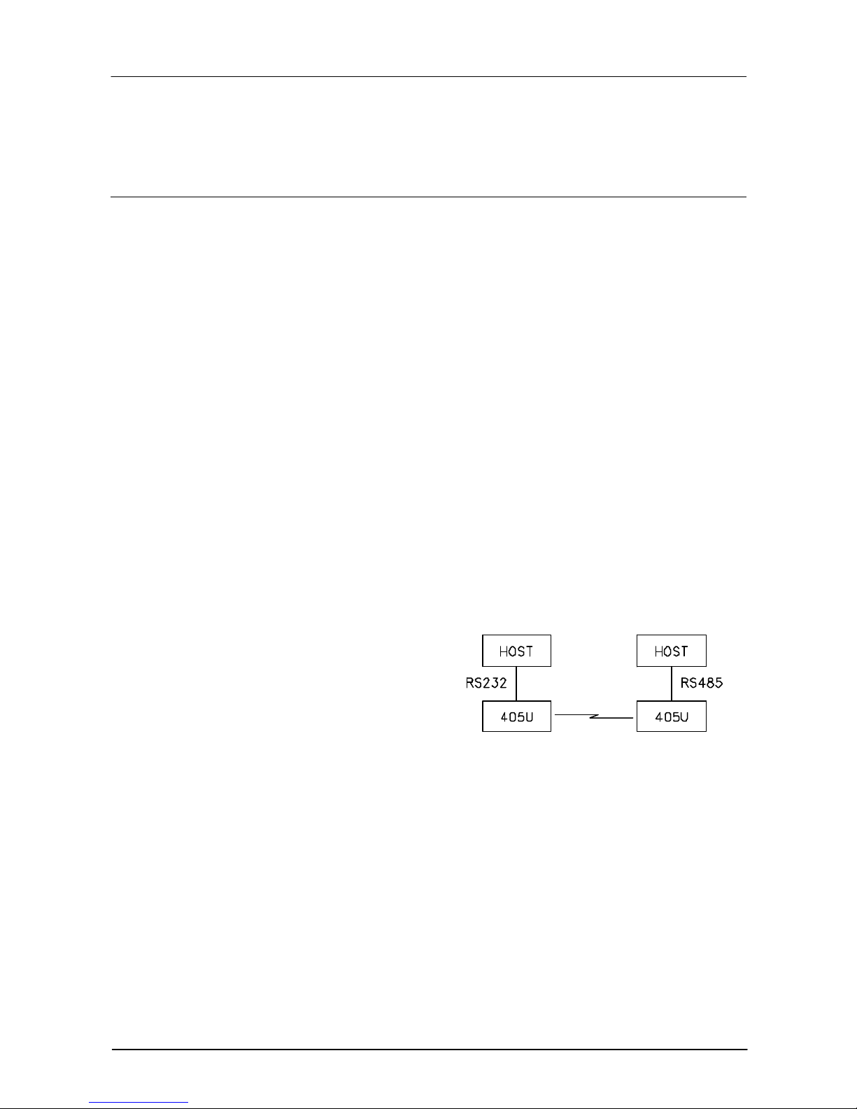
RS232 is an electrical standard format for a full duplex point-to-point serial connection.
RS485 is an electrical standard format for a
half-duplex multidrop serial connection. Up
to 32 devices can communicate on a
common RS485 serial bus. Each 905U-D
unit can only connect to one serial signal either RS232 or RS485. However different
modules in the same system can connect
to different types of serial signals. For
example, RS232 data from one host device
can be transmitted to a remote 905U-D unit
and output as RS485 data to another host device.
The 905U-D has been designed to be flexible enough to cover a wide range of applications.
The user is able to configure many different parameters such that the 905U-D unit will
connect reliably to different types of host devices. Before the radio modem can be used,
these parameters must be configured. Some of these parameters are :-
• Character type - the 905U-D will accept a variety of 7 or 8 data bit characters
• Serial Data Rate - between 75 and 38400 bits/sec
• Radio Data Rate - between 1200 and 9600 bits/sec
• Operating mode - transparent mode or controlled mode .
The operation of the 905U-D radio modem is relatively simple. As data is received at the
serial port, the data is transmitted on the radio channel. Up to 520 bytes of data can be
Chapter One Introduction
Man_905UD_2.0.doc Page 9
transmitted in one transmission. The
radio transmission commences when the
first data byte is received, and ends when
there are no more data bytes in the input
buffer, or when the number of bytes
transmitted equals the maximum message
length (user configurable - default 520
bytes). If more than 520 bytes is input, the
905U-D unit will transmit the first 520
bytes, then the next 520 bytes, and so on
until all of the data has been transmitted.
Because the radio data rate could be less
than the input serial data rate, an input
memory buffer of 8Kbytes is provided.
The RS232 connection provides CTS
control to prevent the buffer overflowing.
There are no data flow control signals for RS485.
A radio channel cannot provide as secure a data channel as a wired connection. The 905UD uses a UHF radio channel with a very low level of natural or industrial noise, however there
is a chance of interference from other users of the unlicensed radio channel. We
recommend that the flow of data over the radio channel is controlled by using error detection
and “handshaking” - that is, returning an acknowledgment transmission if a data packet is
received on the radio channel without error. This function can be performed by either the
host devices or the 905U-D modules. The modules may be configured by the user to
operate in one of two modes. In transparent mode, it is assumed that the host devices
control the flow of data. In controlled mode, the 905U-D units control the flow of data.
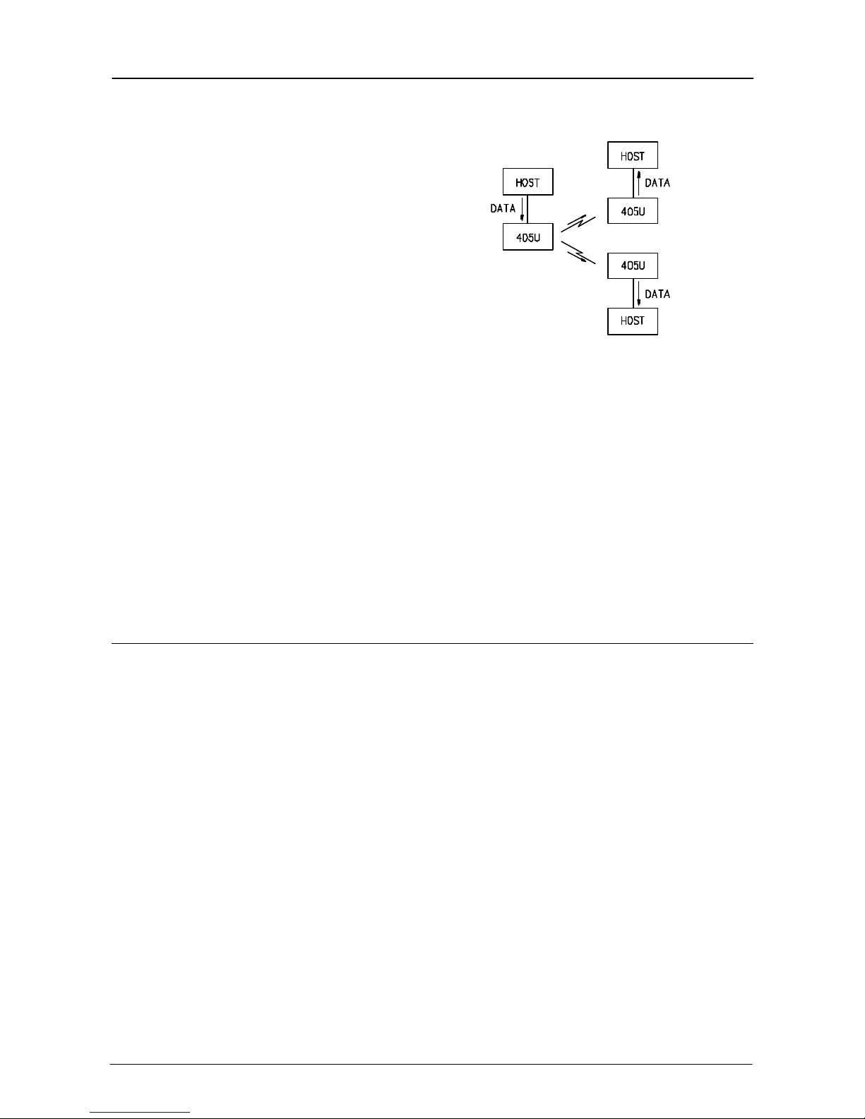
1.2 Transparent Mode
The default configuration of the 905U-D modem is transparent mode - the modules are set
in this mode at the factory. In transparent mode, there is no control of the data
transmissions. Input data is simply transmitted by radio and every other 905U-D unit in that
system which receives the transmission will output the data. This mode relies on the host
devices to perform the “handshaking” function, and re-transmitting serial data if the data is
corrupted (no “handshake”). It also relies on the host devices to include any addressing
necessary in the data. In this mode, modules are not configured with a unit address. Data
is “broadcast” - every other 905U-D in the system will receive the data and output the data
to their individual host devices. The user may configure the 905U-D modems to add error
checking to each data packet transmitted - if error checking is configured, data will not be
output if it is received without a correct error-check. This feature provides additional
protection against corruption of the data during the radio transmission. If error-checking is
not configured, then the data received by radio will be output without checking for errors.
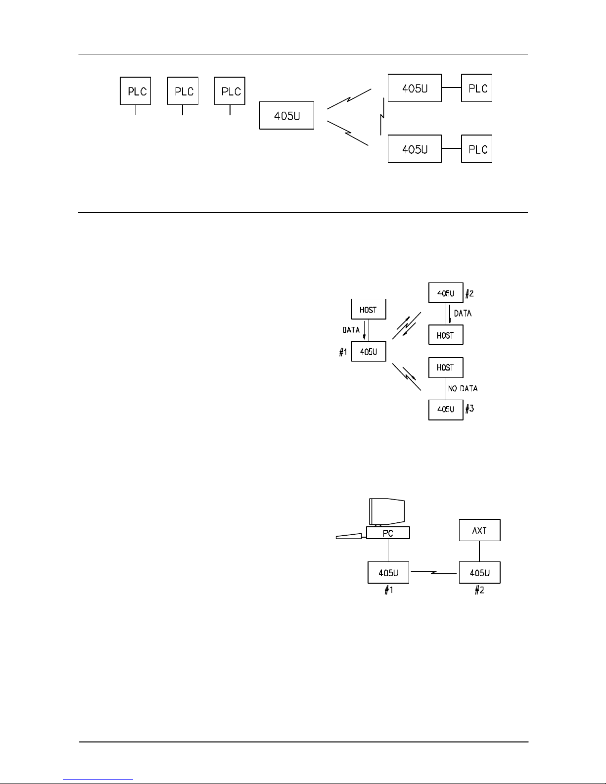
Transparent mode is suitable for a host device which is able to communicate on a multi-drop
“bus” type network. An example of an application is the use of radio modems to extend a PLC
RS485 network. The serial messages from the PLC’s already include PLC addressing and
error detection/correction to control the flow of data.
905U-D Radio Modem Module User Manual
Page 10 © May 2000
1.3 Controlled Mode
In “controlled” mode, the flow of data is controlled by the 905U-D units. Each 905U-D unit is
configured with an address by the user, and a destination address for the data to be
transmitted to. Data is transmitted addressed to the destination module, and only this
module will output the serial data. The source module will add an error-check (16 bit CRC) to
the data transmitted by radio. The
destination module will process the errorcheck, and if correct, it will transmit an
acknowledgment message (ACK) back to
the source module. If the error-check is not
correct, then the destination module will
transmit a “fail” message (NACK) back to
the source module. If the source module
receives a NACK return, or does not
receive any return within 1 second, it will
re-transmit the data. The source module
will attempt to transmit the data up to five
times, until an acknowledgment (ACK) is
received. If an acknowledgment is still not received, then a “communications failure” output
will be activated, and the source module will not accept any more input data from its host
device.
An example of an application using controlled
mode would be a radio modem link between
an intelligent gas analyser and a monitoring
computer system. Intelligent transducers do
not normally provide addressing or error
checking functions - these would be provided
by the 905U-D modules.
In controlled mode, the destination address
may be set by the host device by initially
sending a “Hayes” command to the 905U-D
module, or by on-board miniature switches.
Hayes commands are a standard set of commands used with conventional telephone
modems. An example of an application that would use Hayes command to set destination
addresses would be a central computer polling data loggers for periodic information.
Chapter One Introduction
Man_905UD_2.0.doc Page 11
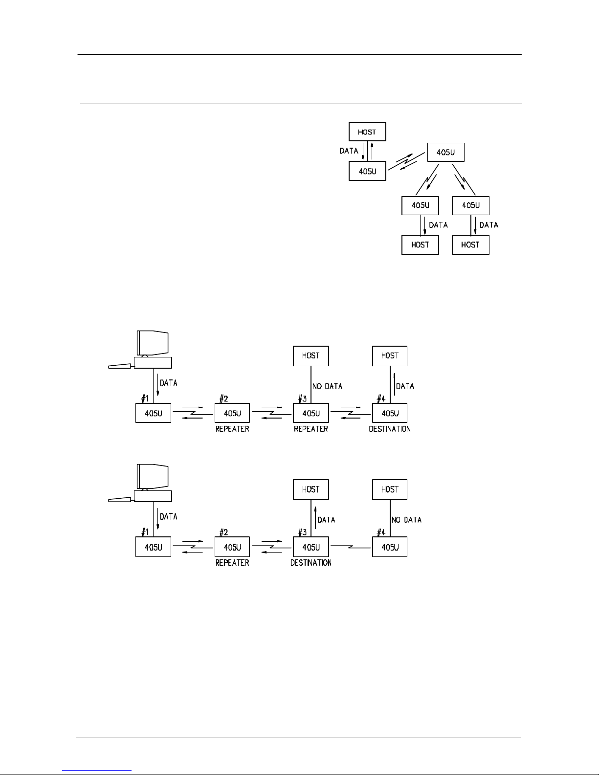
1.4 Repeater Units
A 905U-D unit may be used as a repeater to retransmit radio messages. The purpose of a
repeater unit is to extend radio range.
In transparent mode, only one module per
system may be used as a repeater. If more
than one module is configured as a repeater,
any message transmitted in the system will be
continually re-transmitted between the repeater
units. The repeater in transparent mode will
repeat every transmission it receives.
In controlled mode, up to five repeaters may be
configured for any transmission path.

905U-D Radio Modem Module User Manual
Page 12 © May 2000
Chapter Two INSTALLATION
2.1 General
The 905U-D module is housed in an rugged aluminium case, suitable for DIN-rail mounting.
Terminals will accept wires up to 2.5 sqmm in size.
Normal 110-240V mains supply should not be connected to any terminal of the 905U-D
module. Refer to Section 2.3 Power Supply .
Before installing a new system, it is preferable to bench test the complete system.
Configuration problems are easier to recognise when the system units are adjacent.
Following installation, the most common problem is poor communications caused by
incorrectly installed aerials, or radio interference on the same channel, or the radio path being
inadequate. If the radio path is a problem (ie path too long, or obstructions in the way), then
higher performance aerials or a higher mounting point for the aerial may rectify the problem.
Alternately, use an intermediate 905U-D Module as a repeater.
The foldout sheet 905U-D Installation Guide provides an installation drawing appropriate to
most applications. Further information is detailed below.
Each 905U-D module should be effectively earthed via the "GND" terminal on the 905U-D
module - this is to ensure that the surge protection circuits inside the 905U-D module are
effective.
2.2 Aerial Installation
The 905U-D module will operate reliably over large distances. The distance which may be
reliably achieved will vary with each application - depending on the type and location of
aerials, the degree of radio interference, and obstructions (such as hills or trees) to the radio
path. See the 905U-D Installation Guide for expected ranges in your country. Note that the
expected range is for radio data rates of up to 4800 bits/sec. If 9600 bit/sec rate is
configured, the transmitted data will not have the same range. The radio range for 9600
bit/sec rate will be approx 70% of the range at lower data rates.
Where it is not possible to achieve reliable communications between two 905U-D modules,
then a third 905U-D module may be used to receive the message and re-transmit it. This
module is referred to as a repeater.
An aerial must be connected to each 905U-D module using the BNC female connector at the
top of the module.
To achieve the maximum transmission distance, the aerials should be raised above
intermediate obstructions such that the radio path is true “line of sight”. Because of the
curvature of the earth, the aerials will need to be elevated at least 5 metres above ground for
paths greater than 5 km (3 miles). For short distances, the modules will operate reliably with
some obstruction of the radio path. Obstructions which are close to either aerial will have
more of a blocking effect than obstructions in the middle of the radio path. For example, a
group of trees around the aerial is a large obstruction, and the aerial should be raised above
the trees. However if there is at least 100 metres of clear path before a group of trees, the
trees will have little affect on the radio path.

Chapter Two Installation
Man_905UD_2.0.doc Page 13
An aerial should be connected to the module via 50 ohm coaxial cable (eg RG58 or RG213)
terminated with a male BNC connector. The higher the aerial is mounted, the greater the
transmission range will be, however as the length of coaxial cable increases so do cable
losses. For use on unlicensed frequency channels, there are several types of aerials
suitable for use. It is important aerials are chosen carefully to avoid contravening the
maximum power limit on the unlicensed channel - if in doubt refer to an authorised service
provider.
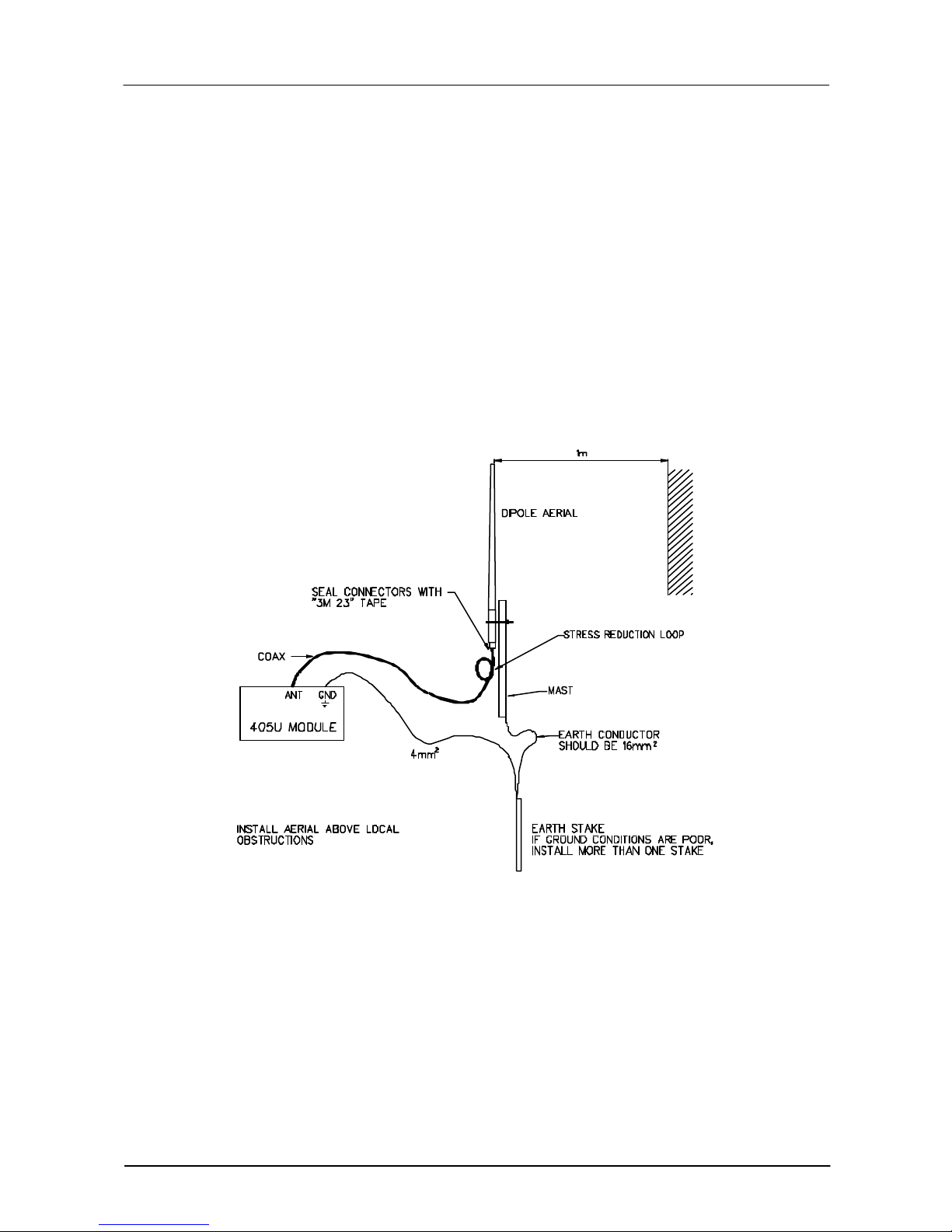
Connections between the aerial and coaxial cable should be carefully taped to prevent
ingress of moisture. Moisture ingress in the coaxial cable is a common cause for problems
with radio systems, as it greatly increases the radio losses. We recommend that the
connection be taped with a layer of PVC insulating tape, then a layer of vulcanising tape such
as “3M 23 tape”, with a final layer of PVC insulating tape.
Where aerials are mounted on elevated masts, the masts should be effectively earthed to
avoid lightning surges. Although the 905U-D module is fitted with surge protection, additional
surge suppression devices are recommended if lightning surge problems are experienced. If
the aerial is not already shielded from lightning strike by an adjacent earthed structure, a
lightning rod may be installed above the aerial to provide shielding.
2.2.1 Dipole aerial.
A unity gain dipole is the normal aerial for use on unlicensed channels. As it does not provide
any gain, then the power transmitted from the aerial will be the same as the power out of the
module, and hence will not exceed the permitted power of the unlicensed channel.
For marginal radio paths, the following lengths are the recommended maximum for the
coaxial cable to the dipole aerial. RG58 10 metres RG213 20 metres. Note that this
applies to marginal paths only - if the radio path has a strong radio signal, then longer
lengths of cable ( and hence more cable loss) can be tolerated. If more than 20 metres of
cable is required for a marginal path installation, then a low loss cable such as RG9913
should be used. Alternatively, a higher gain aerial may be used to compensate for losses.
Dipole aerials should be mounted vertically, at least 1 metre away from a wall or mast.
2.2.2 Three element Yagi aerial.
A 3 element Yagi aerial provides approx 4 dB of gain. This may be used to compensate for
coaxial cable loss for installations with marginal radio path. Note that these aerials should not
be used if the coaxial cable lengths are less than the following minimum lengths, otherwise
the power transmitted from the aerial will exceed the power permitted for the unlicensed
channel.
RG58 10 metres
RG213 20 metres.
Yagi aerials are directional. That is, they have positive gain to the front of the aerial, but
negative gain in other directions. Hence Yagi aerials should be installed with the central
beam horizontal and must be pointed exactly in the direction of transmission to benefit from
the gain of the aerial. Also note that Yagi aerials normally have a drain hole on the folded
element - the drain hole should be located on the bottom of the installed aerial.
905U-D Radio Modem Module User Manual
Page 14 © May 2000
The Yagi aerials may be installed with the elements in a vertical plane (vertically polarised) or
in a horizontal plane (horizontally polarised). For a two station installation, with both modules
using Yagi aerials, horizontal polarisation is recommended. If there are more than two
stations transmitting to a common station, then the Yagi aerials should have vertical
polarisation, and the common (or “central”) station should have a dipole or collinear aerial.
Yagi aerials should not be used where a module is receiving messages from more than one
other module such as repeater of “base-station” situations. An omni-directional aerials such
as a dipole or a collinear aerial should be used.
2.2.3 Collinear (3dB) aerial.
A 3dB collinear aerial may be used in the same way as a 3 element Yagi to compensate for
the losses in long lengths of coaxial cable. This type of aerial is generally used at a central
site with more than one remote site. The collinear aerial looks similar to the dipole, except
that it is longer.
Chapter Two Installation
Man_905UD_2.0.doc Page 15
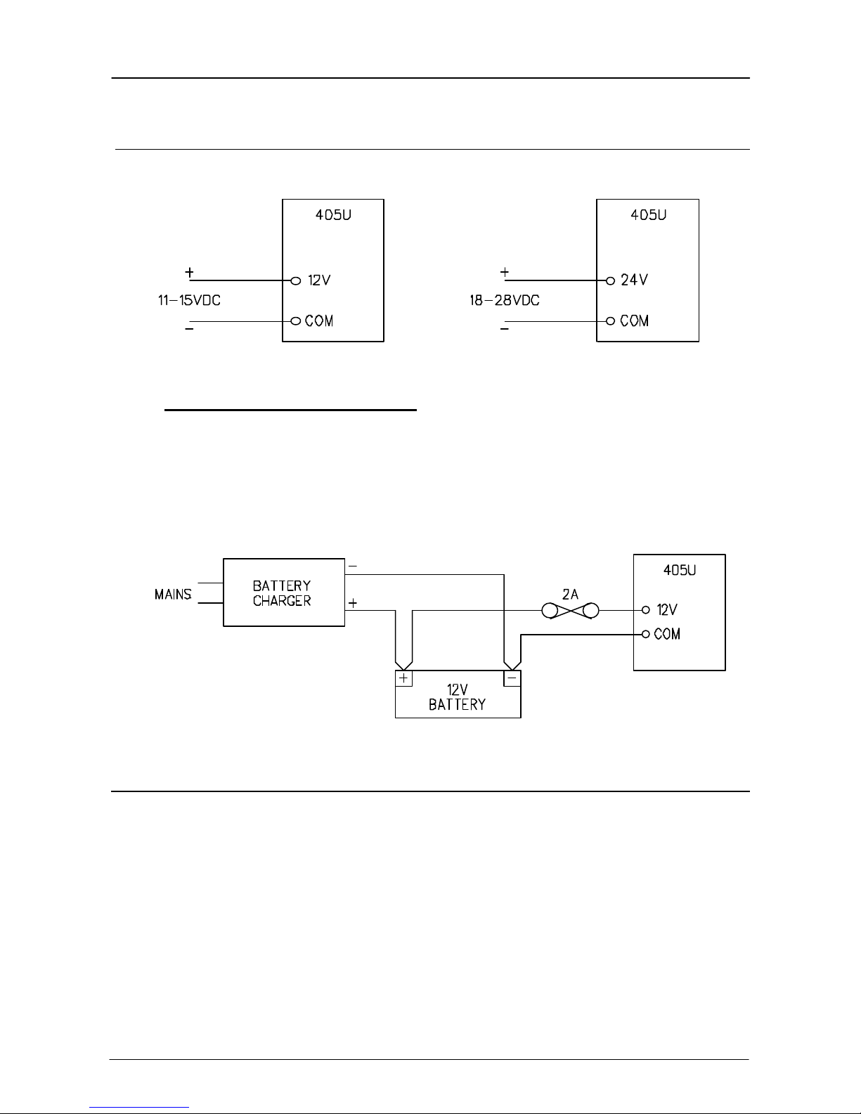
2.3 Power Supply
The 905U-D module may be powered by either a 12VDC or a 24VDC supply.
The negative side of the supply is connected to "COM" and may be connected to “ground”.
The supply negative is connected to the “GND” terminal internally. The positive side of the
supply must not be connected to earth. The DC supply may be a floating supply or
negatively grounded.
The 12V supply is suitable for an unregulated DC supply. Where battery backup is required,
a 12V battery charger may be used to supply the 905U-D module as well as charging the
battery.
The power requirements of the 905U-D units is 155mA at 12VDC or 100mA at 24VDC. The
supply is protected by an internal 1A fuse, accessible at the bottom of the unit.
2.4 Serial Connections
2.4.1 RS232 Serial Port
The serial port is a 9 pin DB9 female and provides for connection to a host device as well as
a PC terminal for configuration, field testing and for factory testing. This port is internally
shared with the RS485 - ensure that the RS485 is disconnected before attempting to use the
RS232 port. Communication is via standard RS232 signals. The 905U-D is configured as
DCE equipment with the pinout detailed below.
905U-D Radio Modem Module User Manual
Page 16 © May 2000
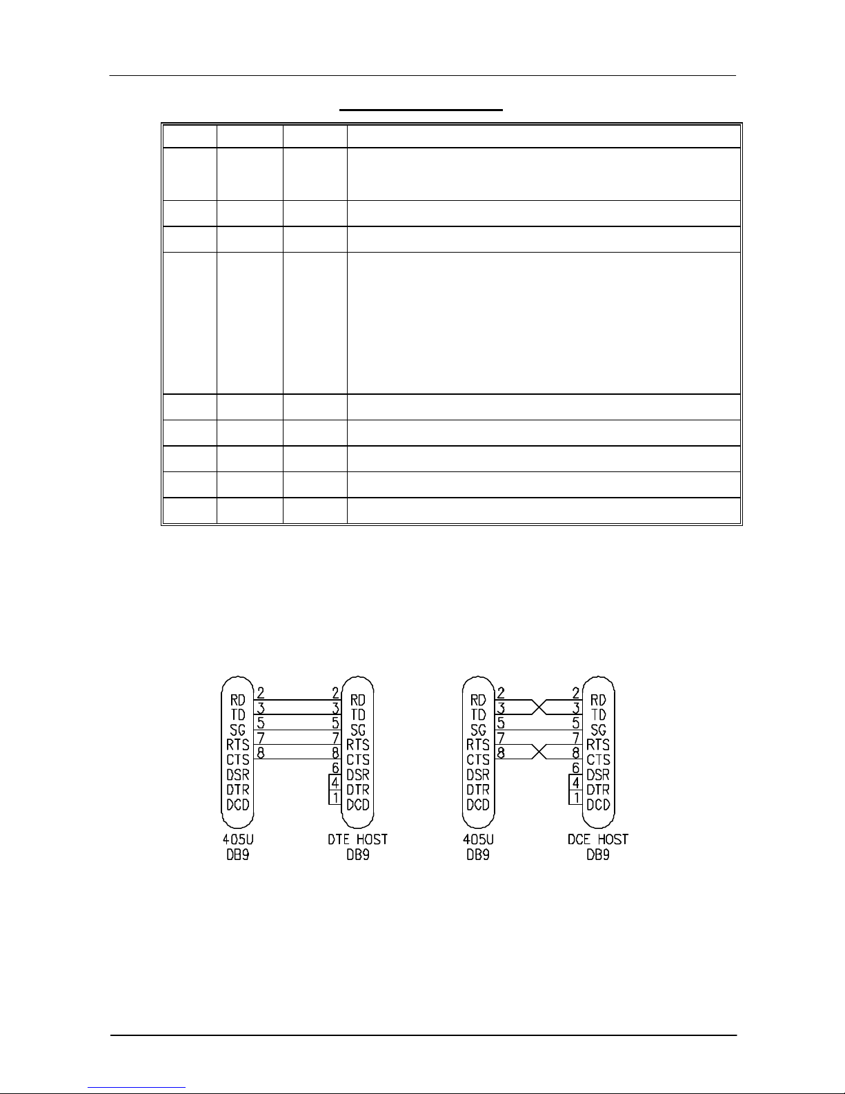
DB9 Connector Pinout
Pin Name Direction Function
1 DCD Out
2 RD Out Transmit Data - Serial Data Output
3 TD In Receive Data - Serial Data Input
4 DTR In
5 SG Signal Ground
6 DSR Out Data Set Ready - always high when unit is powered on.
Data carrier detect - not connected Rev. 1.03 software & earlier
Rev. 1.04 & later - driven when link is established in controlled mode
- driven always in transparent mode
Data Terminal Ready - not connected Rev 1.03 & earlier,
Rev. 1.04 & later: When in controlled mode, will autodial if destination
address is configured In control mode, an inactive DTR will force the 905UD to low-power mode.
Rev. 1.11 & later: When in controlled mode, will autodial if destination
address is configured In control mode, an inactive DTR will force the 905UD stop communicating by radio. If low power mode is selected, an inactive
DTR will also force the 905U-D to low power mode.
7 RTS In Request to Send - hardware flow control
8 CTS Out Clear to send - hardware flow control
9 RI Ring indicator - not used or connected
Hardware handshaking using the CTS/RTS lines is provided. The CTS/RTS lines may be
used to reflect the status of the local unit’s input buffer, or may be configured to reflect the
status of CTS/RTS lines at the remote site. The 905U-D does not support XON/XOFF.
Example cable drawings for connection to a DTE host (a PC) or another DCE host (or
modem) are detailed below. These example are for transparent mode. Controlled mode
may require the use of DTR or DCD signals.
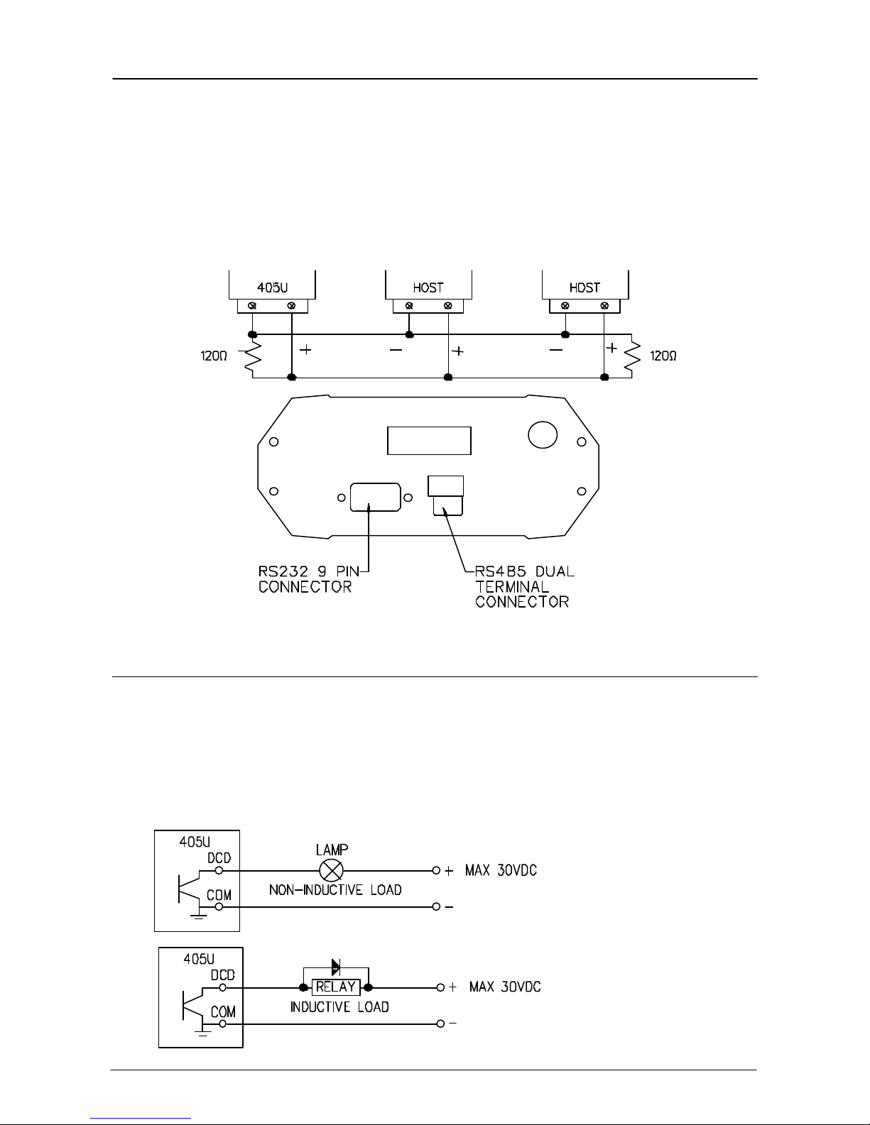
2.4.2 RS485 Serial Port
The RS485 port provides for communication between the 905U-D unit and its host device
using a multi-drop cable. Up to 32 devices may be connected in each multi-drop network.
Note that the RS485 port is shared internally with the RS232 port - make sure that the RS232
port is disconnected before using the RS485 port.
Chapter Two Installation
Man_905UD_2.0.doc Page 17
As the RS485 communication medium is shared, only one of the units in the system may
send data at any one time. Thus communication protocols based on the RS-485 standard
require some type of arbitration. The 905U-D “holds off” for three character times after
receiving data from the RS-485 port before transmitting on the RS-485 port.
RS485 is a balanced, differential standard but it is recommended that shielded, twisted pair
cable be used to interconnect modules to reduce potential RFI. An RS485 network should be
wired as indicated in the diagram below and terminated at each end of the network with a 120
ohm resistor. It is important to maintain the polarity of the two RS485 wires.
- +
2.5 Communications OK (DCD) Output
The 905U-D provides a digital output signal to indicate “communications OK” in controlled
mode. The DCD (data carrier detect) output is “on” or active when a radio link has been
established with the destination module. The output will reset (switch “off”) if a
communications failure occurs. If the 905U-D unit does not receive an acknowledgment
message after attempting to transmit a data packet five times, it will reset the DCD output.
The output is a FET output to common, rated at 30VDC 500 mA.

905U-D Radio Modem Module User Manual
Page 18 © May 2000
Chapter Three OPERATION
3.1 Power-up and Normal Operation
When power is initially connected to the 905U-D module, the module will perform internal
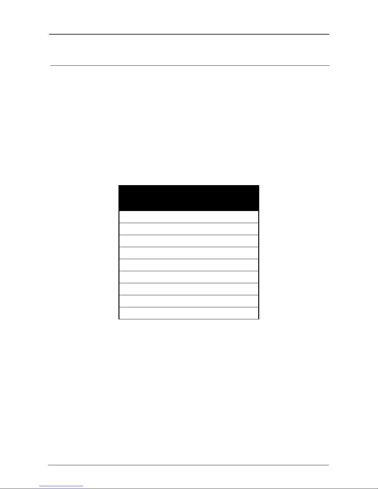
diagnostics to check its functions. The following table details the status of the indicating
LEDs on the front panel under normal operating conditions.
LED Indicator Condition Meaning
OK On Normal Operation
Radio RX GREEN flash
RED flash
Radio TX Flash Radio Transmitting
Serial RX GREEN flash
RED flash
GREEN continuously
Serial TX GREEN flash Serial Port Transmitting
DCD On Transparent mode - always on
Controlled mode - on when
communications link is established
DCD Off Communications failure or link not
Other conditions indicating a fault are described in Chapter Six Troubleshooting.
Low Power Operation
Radio receiving data
Weak radio signal
Serial Port Receiving
CTS low
Configuration Mode
established
The 905U-D may be forced to a low power condition where it switches off its receiver power consumption is reduced to approx 20% of normal. The low power condition will occur
if the 905U-D is configured for controlled mode (modes 6 or 7), AND if an autodial address is
configured, AND if the low power mode feature is configured in the “character type”
selection, AND if the DTR signal is “low” or “off”.
The use of this low power operation may be applicable in remote locations where there is a
limited power supply such as solar panels. In this situation, the DTR signal from the host
device is used to “wake-up” the 905U-D unit. The 905U-D unit will then operate normally until
the DTR signal is reset by the host device.
Chapter Three Operation
Man_905UD_2.0.doc Page 19
3.2 Serial and Radio Data
Data input at the serial port is placed into the input buffer. This buffer will store 8Kbytes of
data, and CTS control is provided on the RS232 port to prevent overflow.
When the 905U-D unit detects data in the input buffer, it initiates a radio message. The radio
message will end when the number of transmitted bytes reaches the maximum message
length (configurable by the user). The message will also end if the input buffer becomes
empty, however the radio transmitter will remain active for a delay time in case more bytes
are input at the serial port. The delay time is called the “tail time” and is configurable by the
user.
3.2.1 Character Type
The 905U-D may be configured by the user to recognise the following types of characters.
Data
Bits
7 1 1 even
7 1 1 odd
7 1 2 none
7 1 2 even
7 1 2 odd
8 1 1 none
8 1 1 odd
8 1 1 even
8 1 2 none
Most applications will require the character type to be the same at each 905U-D
modem in the system. Nevertheless, the character type may be configured to be
different at different 905U-D modems. Data is transmitted by radio as an eight-bit
byte without stop or start bits. If the input data is 7 data bits without parity, then the
byte transmitted by radio comprises the 7 bits plus a zero bit. If the input data is 7
data bits with parity, then the byte transmitted comprises the same byte. Input
characters with 8 bits are transmitted as just the 8 data bits, with no parity. Because
the data may be transmitted without parity, the user may configure CRC error
checking to be added to each transmitted data packet. Data is output at the
destination module based on the character type configured at that module - that is,
the start/stop bits and parity is added to the radio data.3.2.2 Serial Data Rate
Start
Bits
Stop
Bits Parity
The communications baud rates supported on both the RS232 serial port and the RS485
serial port are 50, 75, 150, 300, 600, 1200, 2400, 4800, 9600, 19200, and 38400 baud - the
user selects one of these rates during the configuration of the modem.
 Loading...