

ELPRO 805U-E User Manual

User M
805U-E Wirele
anual
ss Ethernet
ELPRO Technologies Pty Ltd, 9/12 Billabong Street, Stafford Q 4053, Australia.
Tel: +61 7 33524533 Fax: +61 7 33524577 Email: sales@elprotech.com
Web: www.elprotech.com

805U-E Wireless Ethernet User Manual
Thank you for your selection of the 805U-E Wireless Ethernet Modem. We trust it
will give you many years of valuable service.
ATTENTION!
Incorrect termination of supply wires may
cause internal damage and will void warranty.
To ensure your 805U-E enjoys a long life,
double check ALL your connections with
the user’s manual
before turning the power on.
Caution!
For continued protection against risk of fire, replace the internal module fuse only with the same
type and rating.
CAUTION:
Antennas used with this device must be installed to provide a separation distance of at least 20 cm
from all persons to satisfy RF exposure compliance.
DO NOT:
operate the transmitter when someone is within 20 cm of the antenna
operate the transmitter unless all RF connectors are secure and any open connectors are properly
terminated.
operate the equipment near electrical blasting caps or in an explosive atmosphere
All equipment must be properly grounded for safe operations. All equipment should be serviced
only by a qualified technician.
Man_805U-E Rev 1.5 Page 2

Important Notices
Important Notice
ELPRO products are designed to be used in industrial environments, by experienced industrial
engineering personnel with adequate knowledge of safety design considerations.
ELPRO radio products are used on unprotected license-free radio bands with radio noise and
interference. The products are designed to operate in the presence of noise and interference,
however in an extreme case, radio noise and interference could cause product operation delays or
operation failure. Like all industrial electronic products, ELPRO products can fail in a variety of
modes due to misuse, age, or malfunction. We recommend that users and designers design
systems using design techniques intended to prevent personal injury or damage during product
peration, and provide failure tolerant systems to prevent personal injury or damage in the event
o
of product failure. Designers must warn users of the equipment or systems if adequate protection
against failure has not been included in the system design. Designers must include this Important
Notice in operating procedures and system manuals.
These products should not be used in non-industrial applications, or life-support systems, without
consulting ELPRO Technologies first.
1. A radio license is not required in some countries, provided the module is installed using
the aerial and equipment configuration described in the 805U-E Installation Guide. Check
with your local distributor for further information on regulations.
2. Operation is authorized by the radio frequency regulatory authority in your country on a
non-protection basis. Although all care is taken in the design of these units, there is no
responsibility taken for sources of external interference. Systems should be designed to be
tolerant of these operational delays.
3. To avoid the risk of electrocution, the aerial, aerial cable, serial cables and all terminals of
the 805U-E module should be electrically protected. To provide maximum surge and
lightning protection, the module should be connected to a suitable earth and the aerial,
aerial cable, serial cables and the module should be installed as recommended in the
Installation Guide.
4. To avoid accidents during maintenance or adjustment of remotely controlled equipment,
all equipment should be first disconnected from the 805U-E module during these
adjustments. Equipment should carry clear markings to indicate remote or automatic
operation. E.g. "This equipment is remotely controlled and may start without warning.
Isolate at the switchboard before attempting adjustments."
5. The 805U-E module is not suitable for use in explosive environments without additional
protection.
Page 3 © April 2007

805U-E Wireless Ethernet User Manual
Limited Lifetime Warranty, Disclaimer and Limitation of Remedies
ELPRO products are warranted to be free from manufacturing defects for the “serviceable
lifetime” of the product. The “serviceable lifetime” is limited to the availability of electronic
components. If the serviceable life is reached in less than three years following the original
purchase from ELPRO, ELPRO will replace the product with an equivalent product if an
equivalent product is available.
This warranty does not extend to:
- failures caused by the operation of the equipment outside the particular product's
specification, or
- use of the module not in accordance with this User Manual, or
- abuse, misuse, neglect or damage by external causes, or
- repairs, alterations, or modifications undertaken other than by an authorized Service Agent.
ELPRO’s liability under this warranty is limited to the replacement or repair of the product. This
warranty is in lieu of and exclusive of all other warranties. This warranty does not indemnify the
purchaser of products for any consequential claim for damages or loss of operations or profits and
ELPRO is not liable for any consequential damages or loss of operations or profits resulting from
the use of these products. ELPRO is not liable for damages, losses, costs, injury or harm incurred as
a consequence of any representations, warranties or conditions made by ELPRO or its
representatives or by any other party, except as expressed solely in this document.
Man_805U-E Rev 1.5 Page 4

Chapter One Introduction
CONTENTS
CHAPTER ONE INTRODUCTION............................................................................7
1.1 N
1.2 G
ETWORK TOPOLOGY
ETTING STARTED QUICKLY
.....................................................................................................7
..........................................................................................9
CHAPTER TWO INSTALLATION .............................................................................10
2.1 G
2.2 A
ENERAL
NTENNA INSTALLATION
......................................................................................................................10
.............................................................................................10
2.2.1 Dipole and Collinear antennas................................................................................. 11
2.2.2 Yagi antennas........................................................................................................... 12
2.3 P
2.4 S
OWER SUPPLY
ERIAL CONNECTIONS
.............................................................................................................14
..................................................................................................14
2.4.1 RS232 Serial Port ................................................................................................14
2.4.2 RS485 Serial Port ................................................................................................15
2.5 D
ISCRETE (DIGITAL) INPUT/OUTPUT
............................................................................17
CHAPTER THREE OPERATION.............................................................................18
3.1 S
3.2 D
3.3 C
TART-UP
EFAULT CONFIGURATION
ONFIGURING THE UNIT FOR THE FIRST TIME
......................................................................................................................18
...........................................................................................20
..............................................................21
3.3.1 Set PC to same network as 805U-E........................................................................21
3.3.2 Set 805U-E to same network as PC.........................................................................24
3.4 Q
3.5 N
3.6 E
3.7 N
3.8 F
3.9 R
UICK CONFIGURATION
ETWORK CONFIGURATION
THERNET DATA
ORMAL OPERATION
IXED FREQUENCY OPERATION
ADIO CONFIGURATION MENU
..........................................................................................................29
...............................................................................................26
..........................................................................................27
....................................................................................................29
....................................................................................30
.....................................................................................30
3.9.1 Duty Cycle Calculations..........................................................................................33
3.10 S
3.11 R
3.12 W
3.13 S
PANNING TREE ALGORITHM / REDUNDANCY
OUTING RULES
IRELESS MESSAGE FILTERING
ERIAL PORT CONFIGURATION
...........................................................................................................34
...................................................................................36
.....................................................................................39
..............................................................33
3.12.1 RS-232 PPP Server..............................................................................................39
3.12.2 Serial Gateway..................................................................................................... 43
3.12.3 Modbus TCP to RTU Server ...............................................................................45
3.14 D
3.15 M
3.16 R
3.17 C
IGITAL INPUT/OUTPUT AND
ODULE INFORMATION CONFIGURATION
EMOTE CONFIGURATION
ONFIGURATION EXAMPLES
I/O T
RANSFER
............................................................................................52
.........................................................................................53
................................................................46
.....................................................................52
Page 5 © April 2007

805U-E Wireless Ethernet User Manual
CHAPTER FOUR DIAGNOSTICS..................................................................................58
4.1 D
4.2 D
IAGNOSTICS CHART
IAGNOSTIC INFORMATION AVAILABLE
....................................................................................................58
.......................................................................59
4.2.1 Connectivity.........................................................................................................59
4.2.2 Monitor Communications....................................................................................60
4.2.3 Statistics...............................................................................................................60
4.2.3 Statistics...............................................................................................................61
4.2.4 Network Traffic Analysis .................................................................................... 61
4.3 T
4.4 U
ESTING RADIO PATHS
TILITIES
......................................................................................................................62
.................................................................................................62
4.4.1 PING........................................................................................................................62
4.4.2 IPCONFIG...............................................................................................................64
4.4.4 ROUTE....................................................................................................................65
CHAPTER FIVE SPECIFICATIONS .............................................................................67
APPENDIX A FIRMWARE UPGRADE.........................................................................69
APPENDIX B GLOSSARY...............................................................................................74
Man_805U-E Rev 1.5 Page 6

Chapter One Introduction
Chapter One INTRODUCTION
The 805U-E Wireless Ethernet module provides wireless connections between Ethernet devices or
Ethernet wired networks (LAN’s). It has an internal 869 MHz wireless transceiver, which can
be used without a radio license in Europe and South Africa. The 805U-E transmits RF power of
500mW, requiring the transmit duty-factor be limited to 10%.
The 805U-E has a standard RJ45 Ethernet connection which will operate at up to 100Mbit/sec.
The module will transmit the Ethernet messages on the wireless band at up to 76 Kbit/sec.
1.1 Network Topology
The 805U-E is an Ethernet device, and must be configured as part of an Ethernet network. Each
805U-E must be configured as:
an “Access Point” or a “Client”, and
a “Bridge” or a “Router”.
Ethernet
Device
You can also connect to the 805U-E via a RS232 or
RS485 serial port using PPP (point-to-point) protocol.
PPP allows the 805U-E to connect serial
Access
Point
Client
communications into the Ethernet network.
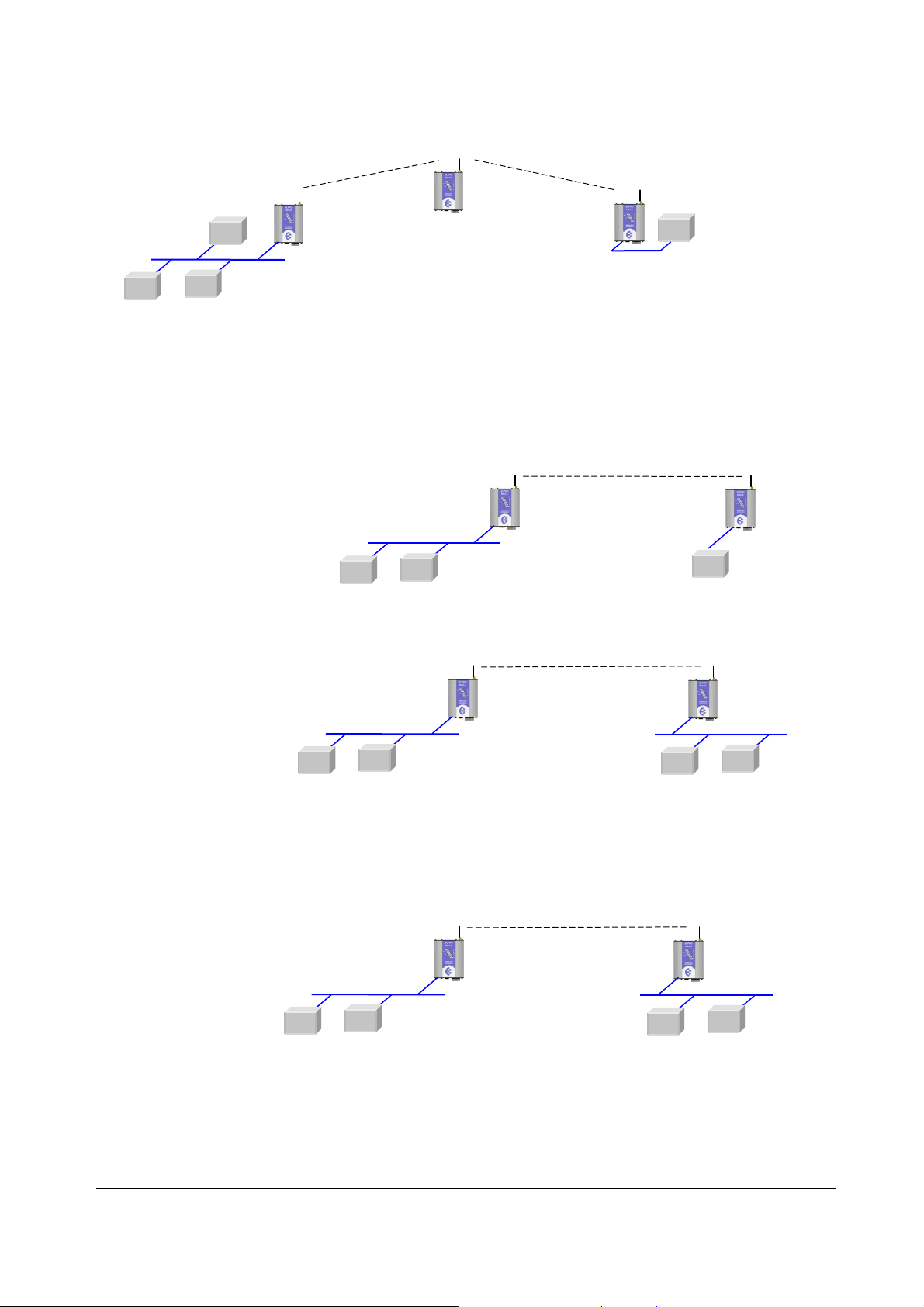
Access Point vs Client
The Access Point unit acts as the “wireless
master” unit. The Access Point sets up the
wireless links to the Client units, and controls
the wireless communications. The first diagram
shows two Ethernet devices being linked. One
Ethernet Device
LAN
Access
Point
Client
805U-E is configured as an Access Point and
one as a Client - in this example it doesn’t mater which unit is the Access Point.
The second diagram shows an existing LAN being extended using 805U-E’s. In this example, the
Access Point should be configured at the LAN
end - although the wireless link will still work
if the Client is at the LAN end.
Client
An Access Point can connect to multiple
Clients. In this case, the Access Point should
be the “central” unit.
LAN
Ethernet Device
Access
Point
Client
Client
Page 7 © April 2007
805U-E Wireless Ethernet User Manual
192.168.0.34
169.254.102.17
192.168.0.34
192.168.0.34
169.254.102.17
An Access Point could be used as a “Repeater” unit to connect two 805U-E Clients which do not
have direct reliable radio paths.
LAN
Ethernet device
Client
Access
Point
Client
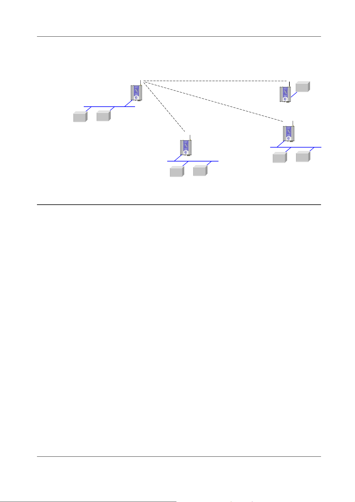
Bridge vs Router
Each 805U-E is configured with an IP address for the Ethernet side, and another for the wireless
side.
A Bridge connects devices within the same Ethernet network - for example, extending an
existing Ethernet LAN. For
192.168.0.34
192.168.0.72
a Bridge, the IP address for
the wireless side is the same
as the Ethernet side.
LAN
Access Point
Bridge
Client
Bridge
192.168.0.72
A Router connects devices
on different LAN’s.
The IP addresses for
192.168.0.34
192.168.0.72
the Ethernet and
wireless sides are
different.
LAN A
Access Point
Bridge
Client
Router
LAN B
In the above example, the wireless link is part of LAN A, with the Client unit acting as a Router
between LAN A and LAN B. Alternately, the Access Point could be configured as a Router -
the wireless link is then part of LAN B.
169.254.102.54
169.254.102.53
LAN A
Access Point
Router
Client
Bridge
LAN B
Man_805U-E Rev 1.5 Page 8
169
.254.102.17
192.168.0.34
169.254.109.40
Chapter One Introduction
There is limit of two Routers within the same radio network. There is no limit to the number of
Bridges in the same network - although there is a limit of 255 Client units linked to any one
Access Point.
LAN A
192.168.0.34
Access Point
Bridge
192.168.0.74
Client
Router
LAN B
Router
Client
Bridge
Client
192.168.0.72
192.168.0.72
192.168.0.73
1.2 Getting Started Quickly
Most applications for the 805U-E require little configuration. The 805U-E has many
sophisticated features, however if you don’t require these features, this section will allow you to
configure the units quickly.
First, read Section 2, “Installation”. The 805U-E requires an antenna and a power supply.
LAN C
Power the 805U-E and make an Ethernet connection to your PC (for further information on
how to do this, refer to section 3.3)
Set the 805U-E address settings as per section 3.4
Save the configuration - the 805U-E is now ready to use.
Before installing the 805U-E, bench test the system. It is a lot easier to locate problems when the
equipment is all together.
There are other configuration setting which may or may not improve the operation of the system.
For detail on these settings, refer to section 3.
Page 9 © April 2007

805U-E Wireless Ethernet User Manual
Chapter Two INSTALLATION
2.1 General
The 805U-E module is housed in an rugged aluminum case, suitable for DIN-rail mounting.
Terminals will accept wires up to 2.5 sqmm in size.
All connections to the module must be SELV. Normal 110-240V mains supply should
not be connected to any terminal of the 805U-E module. Refer to Section 2.3 Power
Supply.
Before installing a new system, it is preferable to bench test the complete system.
Configuration problems are easier to recognize when the system units are adjacent.
Following installation, the most common problem is poor communications caused by
incorrectly installed antennas, or radio interference on the same channel, or the radio path
being inadequate. If the radio path is a problem (ie path too long, or obstructions in the way),
then higher performance antennas or a higher mounting point for the antenna may rectify the
problem. Alternately, use an intermediate 805U-E Module as a repeater.
The foldout sheet 805U-E Installation Guide provides an installation drawing appropriate to
most applications. Further information is detailed below.
Each 805U-E module should be effectively earthed via the "GND" terminal on the 805U-E
module - this is to ensure that the surge protection circuits inside the 805U-E module are
effective.
2.2 Antenna Installation
The 805U-E module will operate reliably over large distances up to 5 km “line-of-sight”. The
distance which may be reliably achieved will vary with each application - depending on the
type and location of antennas, the degree of radio interference, and obstructions (such as hills
or trees) to the radio path.
To achieve the maximum transmission distance, the antennas should be raised above
intermediate obstructions so the radio path is true “line of sight”. The modules will operate
reliably with some obstruction of the radio path, although the reliable distance will be
reduced. Obstructions which are close to either antenna will have more of a blocking affect
than obstructions in the middle of the radio path. For example, a group of trees around the
antenna is a larger obstruction than a group of trees further away from the antenna. The
805U-E modules provide a diagnostic feature which displays the radio signal strength of
transmissions.
Line-of-sight paths are only necessary to obtain the maximum range. Obstructions will
reduce the range, however may not prevent a reliable path. A larger amount of obstruction
can be tolerated for shorter distances. For very short distances, it is possible to mount the
antennas inside buildings. An obstructed path requires testing to determine if the path will be
reliable - refer the section 6 of this manual.
Where it is not possible to achieve reliable communications between two 805U modules, then
a third 805U module may be used to receive the message and re-transmit it. This module is
referred to as a repeater. This module may also have a host device connected to it.
Man_805U-E Rev 1.5 Page 10

Chapter Two Installation
An antenna should be connected to the module via 50 ohm coaxial cable (eg RG58, RG213
or Cellfoil) terminated with a male SMA coaxial connector. The higher the antenna is
mounted, the greater the transmission range will be, however as the length of coaxial cable
increases so do cable losses. For use on unlicensed frequency channels, there are several
types of antennas suitable for use. It is important antenna are chosen carefully to avoid
contravening the maximum power limit on the unlicensed channel - if in doubt refer to an
authorized service provider.
The net gain of an antenna/cable configuration is the gain of the antenna (in dBi) less the loss
in the coaxial cable (in dB).
The maximum net gain of the antenna/cable configuration permitted is 0dB.
The gains and losses of typical antennas are
Antenna Gain (dB)
3dB Collinear 3
6dB Collinear 6
6 element Yagi 10
Cable type Loss (dB per 10 m)
RG58 -5
RG213 -2.5
Cellfoil -3
The net gain of the antenna/cable configuration is determined by adding the antenna gain and
the cable loss. For example, a 6 element Yagi with 20 metres of RG58 has a net gain of 0 dB
(10dB – 10dB).
Connections between the antenna and coaxial cable should be carefully taped to prevent
ingress of moisture. Moisture ingress in the coaxial cable is a common cause for problems
with radio systems, as it greatly increases the radio losses. We recommend that the
connection be taped, firstly with a layer of PVC Tape, then with a vulcanizing tape such as
“3M 23 tape”, and finally with another layer of PVC UV Stabilized insulating tape. The first
layer of tape allows the joint to be easily inspected when trouble shooting as the vulcanizing
seal can be easily removed.
Where antennas are mounted on elevated masts, the masts should be effectively earthed to
avoid lightning surges. For high lightning risk areas, surge suppression devices between the
module and the antenna are recommended. If the antenna is not already shielded from
lightning strike by an adjacent earthed structure, a lightning rod may be installed above the
antenna to provide shielding.
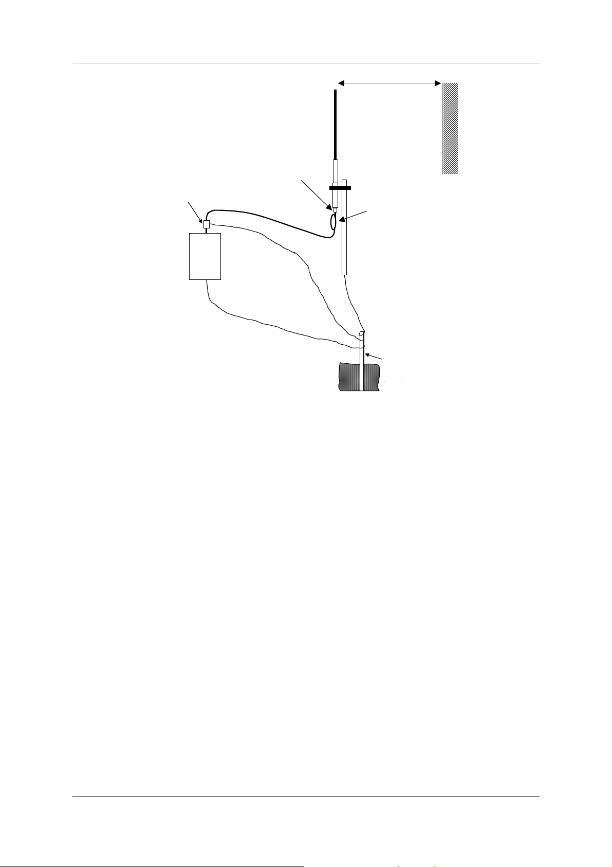
2.2.1 Dipole and Collinear antennas.
A collinear antenna transmits the same amount of radio power in all directions - as such that
are easy to install and use. The dipole antenna with integral 5m cable does not require any
additional coaxial cable, however a cable must be used with the collinear antennas.
Page 11 © April 2007
805U-E Wireless Ethernet User Manual
COLINEAR
EARTH STAKE
INSTALL AERIAL ABOVE
SURGE
WEATHE
RPROOF
PROVIDE GOOD
ARRESTOR
(OPTIONAL)
CONNECTORS WITH
“3M 23” TAPE
COAXIAL CABLE
ANT
805U
GND
LOCAL OBSTRUCTIONS
GROUND
CONNECTION TO
MAST, MODULE
AND SURGE
ARRESTOR
ANTENNA
MAST
1m minimum
STRESS RELIEF LOOP
IF GROUND CONDITIONS ARE
POOR, INSTALL MORE THAN
Collinear and dipole antennas should be mounted vertically, preferably 1 metre away from a
wall or mast to obtain maximum range.
2.2.2 Yagi antennas.
A Yagi antenna provides high gain in the forward direction, but lower gain in other
directions. This may be used to compensate for coaxial cable loss for installations with
marginal radio path.
The Yagi gain also acts on the receiver, so adding Yagi antennas at both ends of a link
provides a double improvement.
Yagi antennas are directional. That is, they have positive gain to the front of the antenna,
but negative gain in other directions. Hence Yagi antennas should be installed with the
central beam horizontal and must be pointed exactly in the direction of transmission to
benefit from the gain of the antenna. The Yagi antennas may be installed with the elements
in a vertical plane (vertically polarized) or in a horizontal plane (horizontally polarized). For
a two station installation, with both modules using Yagi antennas, horizontal polarization is
recommended. If there are more than two stations transmitting to a common station, then the
Yagi antennas should have vertical polarization, and the common (or “central” station
should have a collinear (non-directional) antenna.
Man_805U-E Rev 1.5 Page 12
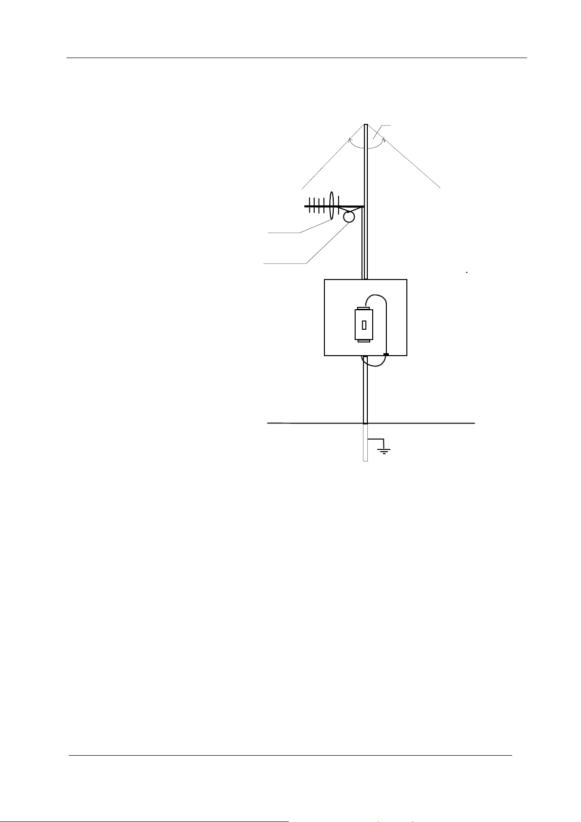
Antenna installed
with drain holes
looped
90
o
Chapter Two Installation
Also note that Yagi antennas normally have a drain hole on the folded element - the drain
hole should be located on the bottom of the installed antenna.
down
Coax feed
805U
Page 13 © April 2007
805U-E Wireless Ethernet User Manual
_
10-30
2.3 Power Supply
The 805U-E module can be powered from a 10 - 30VDC power supply. The power supply
should be rated at 1 Amp. The negative side of the supply should be connected to a good
“ground” point for surge protection. The supply negative is connected to the unit case
internally.
The positive side of the supply
must not be connected to earth.
The DC supply may be a floating
supply or negatively grounded. The
power requirements of the 805U-E
unit is 280mA @ 12V or 150mA
+
@ 24VDC. This is inclusive of
radio and Ethernet ports active, &
serial port plugged in.
Transmission current (500mW RF) is nominally 500mA at 12V, 250mA at 24VDC.
A Ground Terminal is provided on the back of the Module. This Terminal should be
connected to the Main Ground point of the installation in order to provide efficient surge
protection for the Module (Refer to the Installation Diagram)
B
RS485
A
-
SUPPLY
+
COM
DIO
805U-E
2.4 Serial Connections
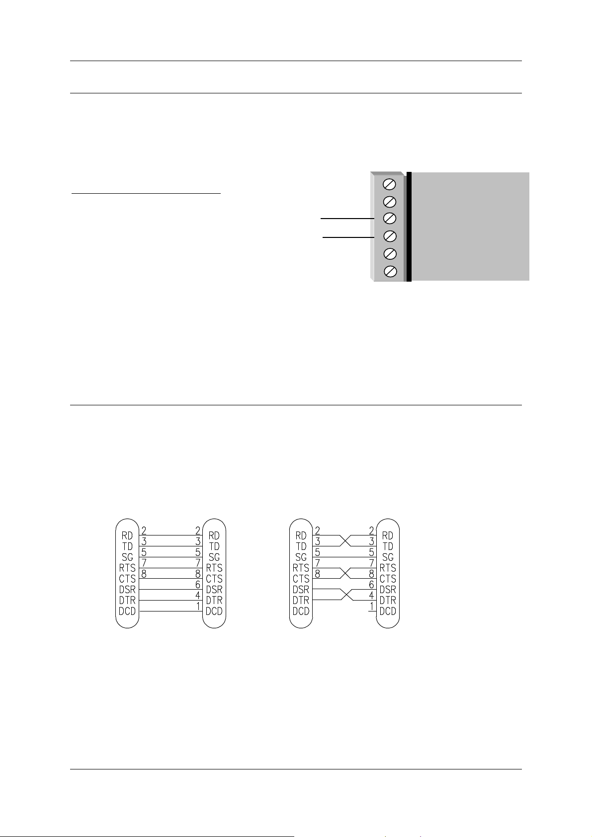
2.4.1 RS232 Serial Port
The serial port is a 9 pin DB9 female and provides for connection to a host device as well as
a PC terminal for configuration, field testing and for factory testing. Communication is via
standard RS232 signals. The 805U-E is configured as DCE equipment with the pinouts
detailed below.
905U-E
DB9
MALE
DTE HOST
DB9
FEMALE
905U-E
DB9
MALE
DCE HOST
DB9
MALE
Hardware handshaking using the CTS/RTS lines is provided. The CTS/RTS lines may be
used to reflect the status of the local unit’s input buffer, or may be configured to reflect the
status of CTS/RTS lines at the remote site. The 805U-E does not support XON/XOFF.
Example cable drawings for connection to a DTE host (a PC) or another DCE hosts (or modem)
are detailed above.
Man_805U-E Rev 1.5 Page 14

Chapter Two Installation
DB9 Connector Pinouts
Pin Name Direction Function
1 DCD Out
2 RD Out
Data carrier detect –
Transmit Data – Serial Data Output
3 TD In
4 DTR In
5 SG
6 DSR Out
7 RTS In
8 CTS Out
9 RI
Receive Data – Serial Data Input
Data Terminal Ready -
Signal Ground
Data Set Ready - always high when unit is powered on.
Request to Send -
Clear to send -
Ring indicator -
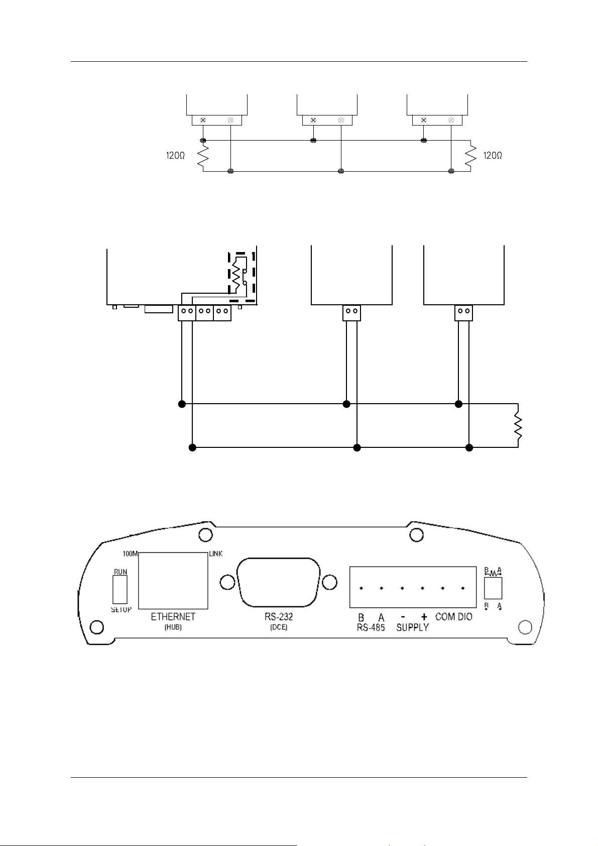
2.4.2 RS485 Serial Port
The RS485 port provides for communication between the 805U-E unit and its host device using
a multi-drop cable. Up to 32 devices may be connected in each multi-drop network.
As the RS485 communication medium is shared, only one of the units on the RS485 cable
may send data at any one time. Thus communication protocols based on the RS-485
standard require some type of arbitration.
RS485 is a balanced, differential standard but it is recommended that shielded, twisted pair
cable be used to interconnect modules to reduce potential RFI. It is important to maintain the
polarity of the two RS485 wires. An RS485 network should be wired as indicated in the
diagram below and terminated at each end of the network with a 120 ohm resistor. On-board
120 ohm resistors are provided and may be engaged by operating the single DIP switch in the
end plate next to the RS485 terminals. The DIP switch should be in the “1” or “on” position
to connect the resistor. If the module is not at one end of the RS485 cable, the switch should
be off.
Page 15 © April 2007
805U-E Wireless Ethernet User Manual
HOST
805U
-E
HOST
Ω
RS485
RS485 CONNECTION USING TERMINATING RESISTOR
DEFAULTS DIP SWITCH
RS485 CONNECTIONS
805U-E
ETHERNET
120
RS232
SUPPLY
DIP SWITCH
FOR 120
DIO
HOST HOST
Ω
120
+
+
+
Man_805U-E Rev 1.5 Page 16
Voltage
-
free
+
V
-
_
Chapter Two Installation
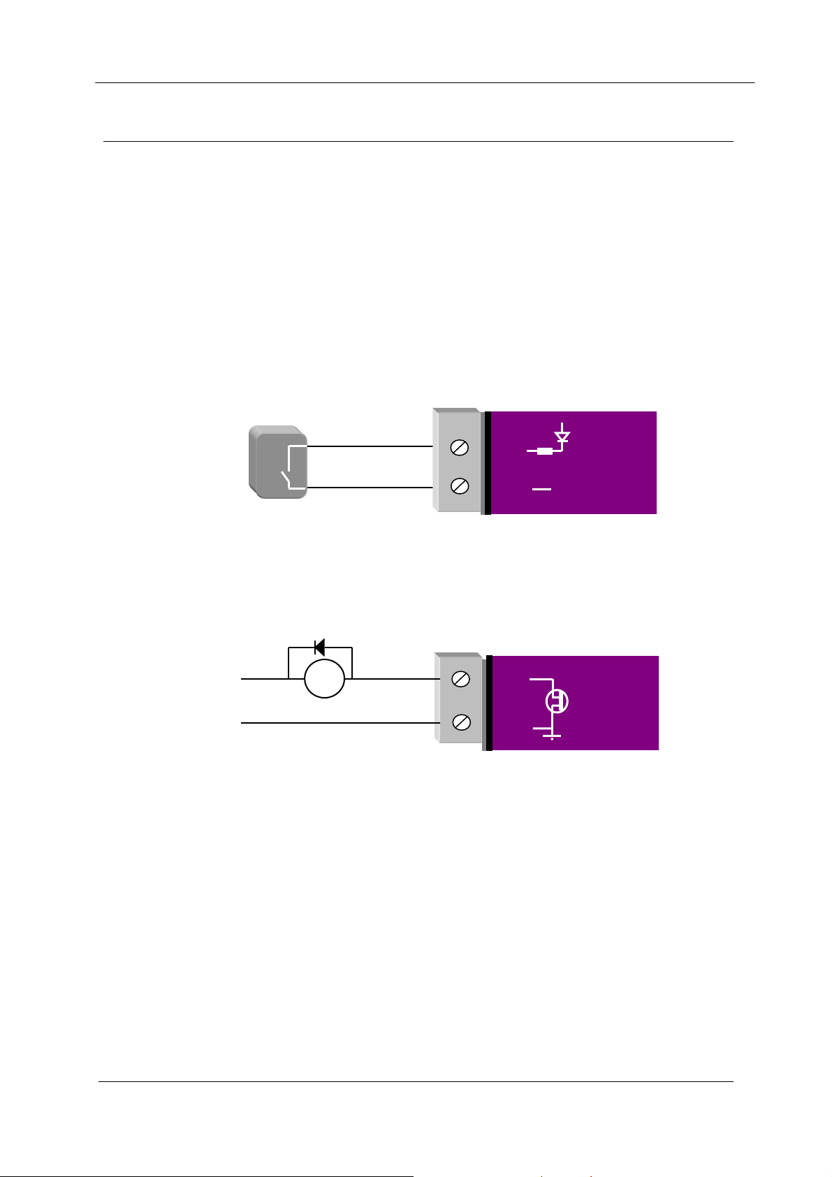
2.5 Discrete (Digital) Input/Output
The 805U-E has one on-board discrete/digital I/O channel. This channel can act as either a
discrete input or discrete output. It can be monitored, or set remotely, or alternatively used to
output a communications alarm status.
If used as an “input”, the I/O channel is suitable for voltage free contacts (such as
mechanical switches) or NPN transistor devices (such as electronic proximity switches). PNP
transistor devices are not suitable. Contact wetting current of approximately 5mA is
provided to maintain reliable operation of driving relays.
The digital input is connected between the "DIO" terminal and common "COM". The I/O
circuit includes a LED indicator which is lit when the digital input is active, that is, when the
input circuit is closed. Provided the resistance of the switching device is less than 200 ohms,
the device will be able to activate the digital input.
contact input
DIO
GND
V
805U-E
The I/O channel may also be used as a discrete output. The digital outputs are transistor
switched DC signals, FET output to common rated at 30VDC 500 mA.
The output circuit is connected to the "DIO" terminal. The digital output circuit includes a
LED indicator which is lit when the digital output is active.
DIO
GND
805U-E
Max 30VDC
0.5A
+
DC
Load
Page 17 © April 2007

805U-E Wireless Ethernet User Manual
Chapter Three OPERATION
3.1 Start-up
“Access Point” Start-up
An Access Point unit starts and immediately begins transmitting periodic messages called
beacons. These beacon messages are messages contain information for Clients on how to
establish a link with the Access Point.
Any Client that hears the messages, which are not already linked to another Access Point
unit, will respond and links will be established between the new Access Point and these
Clients.
“Client” Start-up
When a Client powers up, it immediately scans for messages from Access Point units. The
Client will continue to scan for twice the configured beacon interval in the Client. During the
scan, the RX led will flicker now and again indicating messages received, perhaps from an
Access Point. If the Client finds suitable Access Points during the scan, it will then attempt
to establish a link with the Access Point with the strongest radio signal.
Link Establishment
When the Client wishes to establish a link with an Access Point it follows a two step process.
The first step is “authentication”. During this step the Client and Access Point check if they
can establish a secure link, based upon the configured security encryption.
Once the Client has been authenticated, it will then request a link. This step is called
“association”.
While no links have been established, the LINK led will be OFF. Once a single link has been
established, the LINK led is ON.
After the link is established, data may be transferred in both directions. The Access Point
will act as a master-unit and will control the flow of information to the Clients linked to it.
The maximum number of 255 Clients may be linked to an Access Point.
How a Link connection is lost
The 805U-E will reset the Link if:
• Excessive retries: When a 805U-E unit transmit a wireless message to another unit, the
destination unit will transmit back an acknowledgment. If the source unit does not
receive an acknowledgment, it will re-send the message - this is known as a “re-try”.
Both Access Point and Client will drop the link if the number of retries for a single packet
exceeds (7) times. Packets are retransmitted according to an increasing time delay
between retries, with each attempt on a different frequency.
• Inactivity: During periods of inactivity, Clients will periodically check that the link to the
Access Point remains intact. This process is called “reassociation”, and will occur
approximately (6) beacon intervals after the last packet was sent to the Access Point. If a
Client unit does not get a response from its Access Point, it will retry the reassociating
request (7) times before resetting the link. If an Access Point does not receive any traffic
Man_805U-E Rev 1.5 Page 18

Chapter Three Operation
from a Client, including reassociating requests, within (12) beacon intervals, the Access
Point will reset the link.
After a Client has reset it’s Link status, it will start scanning for an Access Point, as if it has
just started up.
LED Indication
The following table details the status of the indicating LEDs on the front panel under normal
operating conditions.
LED Indicator Condition Meaning
OK GREEN Normal Operation
OK RED Supply voltage too low.
Radio RX GREEN flash Radio receiving data
Radio RX RED flash Weak radio signal
Radio TX Flash Radio Transmitting
Radio LINK On On when a radio communications link is
established
Radio LINK Off Communications failure or radio link not
established
Radio LINK GREEN flash
RED flash
LAN ON Link Established on Ethernet port
LAN Flash Activity on Ethernet port.
Serial GREEN flash RS232 Serial Port Activity
Serial RED flash Rs485 Serial Port Activity
DIO On
DIO Off
Digital Output ON or Input is grounded.
Digital Output OFF and Input is open circuit.
Serial Port Receiving
CTS low
The Ethernet RJ45 port incorporates two indication LEDs. The LINK LED comes on when
there is a connection on the Ethernet port, and will blink off briefly when activity is detected
on the Ethernet Port. The 100MB LED indicates that the connection is at 100 MBit/Sec. The
100MB LED will be off for 10MB/Sec connection.
Other conditions indicating a fault are described in Chapter Six Troubleshooting.
Page 19 © April 2007

805U-E Wireless Ethernet User Manual
3.2 Default Configuration
The default factory configuration of the 805U-E is
• Bridge/Client
• IP address192.168.0.1XX, where XX is the last two digits of the serial number (the
default IP address is shown on the printed label on the back of the module)
• netmask 255.255.255.0
• Username is “user” and the default password is “user”
The 805U-E will temporarily load some factory-default settings if powered up with the
Factory Default switch (on the end-plate of the module) in SETUP position. In the position,
wireless operation is disabled. The previous configuration remains stored in memory and
will only change if a configuration parameter is modified and the change saved.
Do not forget to set the switch back to the RUN position and cycle power at the conclusion
of configuration for resumption of normal operation.
Man_805U-E Rev 1.5 Page 20
Chapter Three Operation
3.3 Configuring the Unit for the First Time
The 805U-E has a built-in webserver, containing webpages for analysis and modification of
configuration. The configuration can be accessed using Microsoft® Internet Explorer. This
program is shipped with Microsoft Windows or may be obtained freely via the Microsoft®
website.
Configuration of IP address, gateway address and subnet mask may also be accessed via the
RS-232 serial port.
Accessing Configuration for the first time
There are two methods for accessing the configuration inside a 805U-E. The first method
requires changing your computer settings so that the configuring PC is on the same network
as the 805U-E with factory default settings. This is the preferred method and is much less
complicated than the second method. You will need a “straight-through” Ethernet cable
between the PC Ethernet port and the 805U-E. The factory default Ethernet address for the
805U-E is 192.168.0.1XX where XX are the last two digits of the serial number (check the
label on the back of the module).
The second method requires setting an IP address in the 805U-E such that it is accessible on
your network without having to change your network settings.
3.3.1 Set PC to same network as 805U-E
Connect the Ethernet cable between unit
and the PC configuring the module.
• Set the Factory Default Switch to the
SETUP position. This will always
start the 805U-E with Ethernet IP
address 192.168.0.1XX, subnet
mask 255.255.255.0, gateway IP
192.168.0.1 and the radio disabled.
Do not forget to set the switch back
to the RUN position and cycle power
at the conclusion of configuration
for resumption of normal operation.
• Power up the 805U-E module.
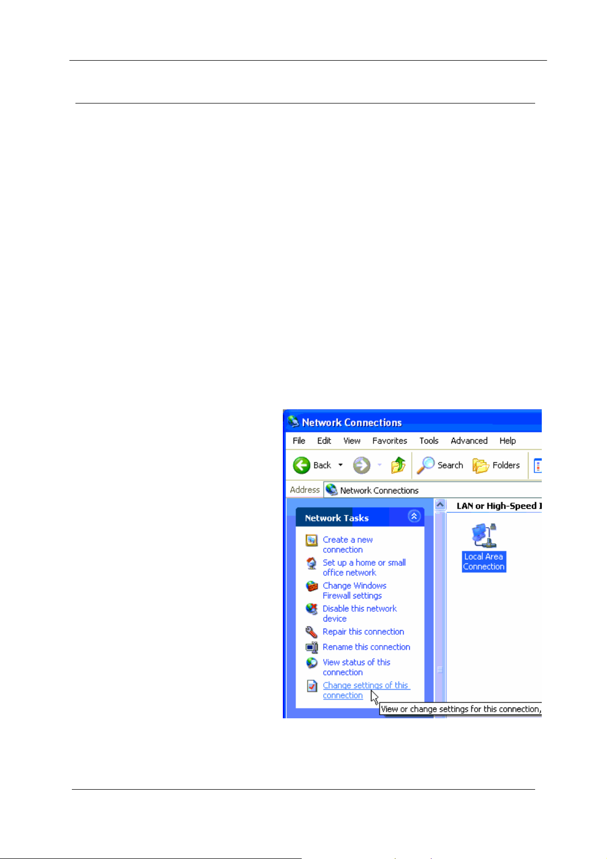
• Open “Network Settings” on your
PC under Control Panel. The
following description is for
Windows XP - earlier Windows
operating systems have similar
settings.
Page 21 © April 2007
805U-E Wireless Ethernet User Manual
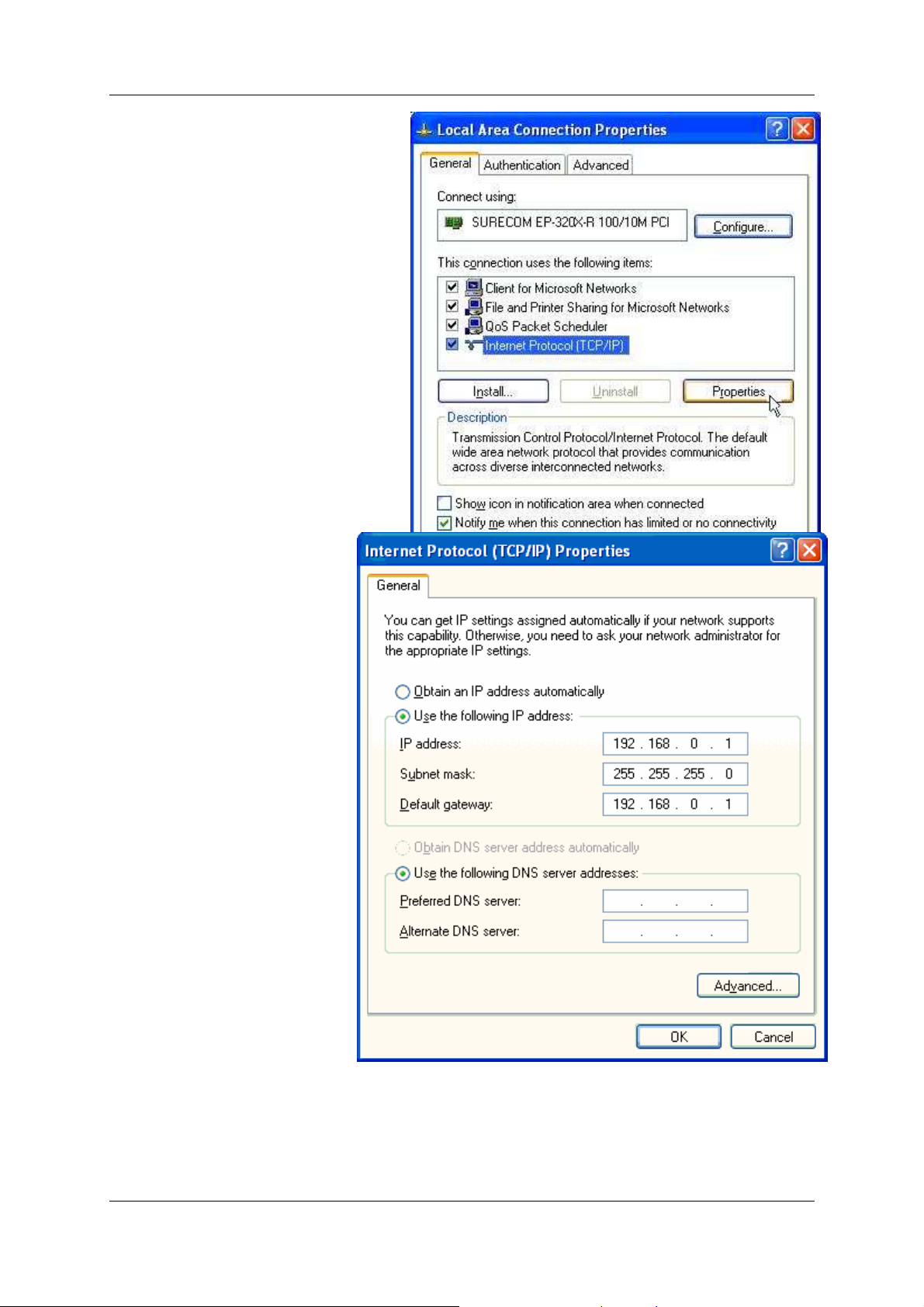
• Open “Properties” of Local Area
Connection.
• Select Internet Protocol (TCP/IP)
and click on Properties.
• On the General tab enter
IP address 192.168.0.1,
Subnet mask
255.255.255.0, and default
gateway 192.168.0.1.
• Open Internet Explorer and ensure that settings will allow you to connect to the IP
address selected. If the PC uses a proxy server, ensure that Internet Explorer will bypass
the Proxy Server for local addresses. This option may be modified by opening Tools ->
Internet Options -> Connections Tab -> LAN Settings->Proxy Server -> bypass proxy for
local addresses.
Man_805U-E Rev 1.5 Page 22
Chapter Three Operation
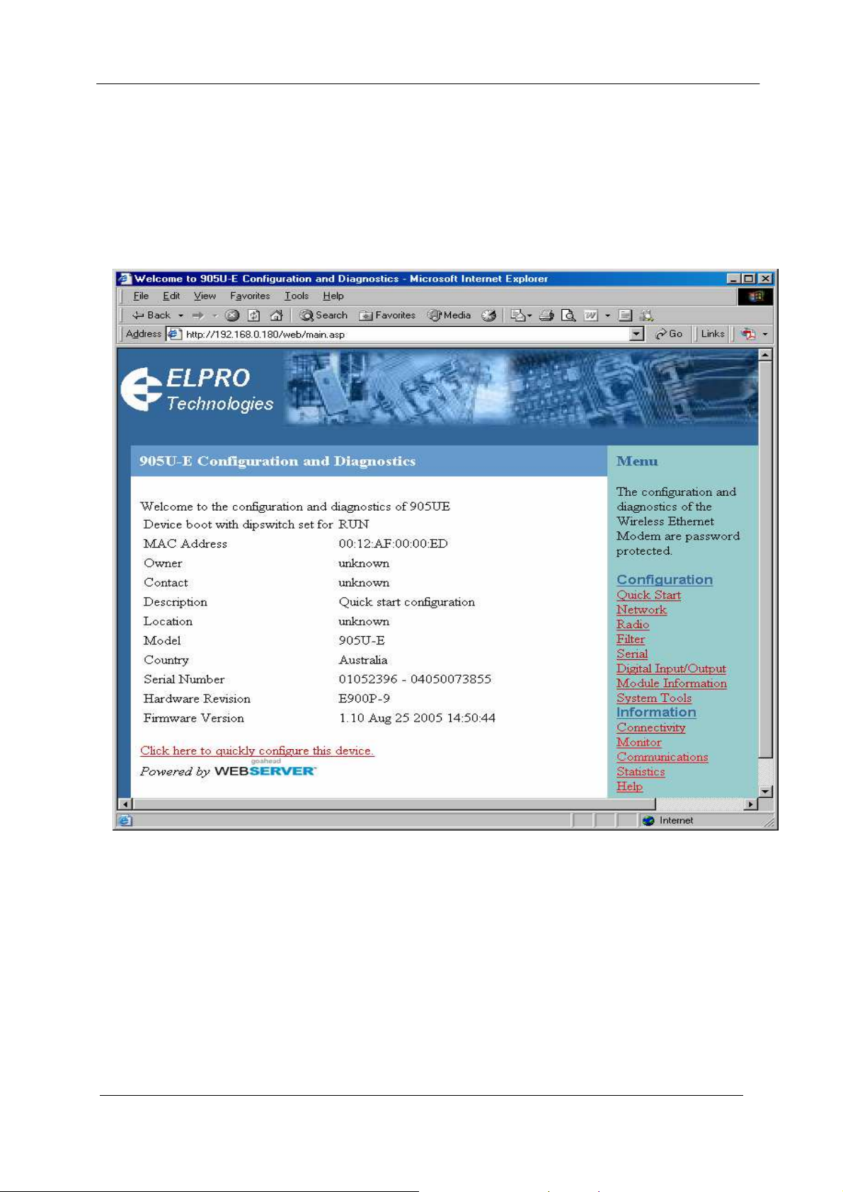
• Enter the default IP address for the 805U-E http://192.168.0.1XX where XX is the last
two digits of the serial number
• A welcome webpage should be displayed as illustrated below.
• Configuration and Diagnostics may be opened by clicking on any of the menu items, and
entering the username “user” and default password “user”. Configure the unit to your
requirements (refer later sections of this manual).
When Configuration is complete, switch Factory Default dip-switch on 805U-E to RUN
position, and cycle power to resume normal configured operation.
Page 23 © April 2007

805U-E Wireless Ethernet User Manual
3.3.2 Set 805U-E to same network as PC
This is the alternate procedure to setting an IP address in the 805U-E. Consult your network
administrator for an IP address on your network, the gateway IP address, and network mask.
a) Switch Factory Default dip-switch on 805U-E to SETUP position.
b) Connect the RS232 port on the 805U-E to the RS232 port on the PC using a “straight-
through” serial cable.
c) Open a terminal package (such as Hyperterminal) with 19200bps data rate, 8 data bit, 1
stop, no parity and no flow control. Make sure that no other programs have control of
the serial port.
d) Power up 805U-E. Basic network settings will be displayed on the terminal as illustrated
below. When prompted, hit enter key to stop automatic boot process. You have 5
seconds to abort the boot process.
My Right Boot 2.1
Copyright 1999-2004 Cybertec Pty Ltd, All rights reserved.
This software is provided by Cybertec ``as is'' and with NO WARRANTY.
http://www.cybertec.com.au/
ROM : 256KB @ 0xffe00000
RAM : 8192KB @ 0x00000000 (141KB / 0x0002366c)
ROM Configuration table ... PASSED.
RAM address pattern check . PASSED.
RAM address bus check ..... PASSED.
Product : E900P R2.3F
Variant : default-variant
Serial No. : 09040569 - 012345678910
Release : epm_mrb_elpro_E900P_1.5
Released date : 11 August 2005
Released host : Anxosity
Build date : Thu Aug 11 12:01:05 2005
Build host : Anxosity
Boot Flags : no RAM test, no ROM test, bus timer on, wdog on
static IP, auto-boot, net-boot, reset on
local file, no binary load
Boot delay : 0
Boot Filename : /memory/0xffe40000,0x60000
Boot Address : 192.168.123.113
Boot Netmask : 255.255.255.0
Boot Gateway : 192.168.123.113
Boot Host : 192.168.123.1
Boot Mac 0 : 00:12:af:00:00:10
Boot Mac 1 : 00:12:af:00:00:10
RTE data store .... no error
Setting bus timer (on) and watchdog (on) ... PASSED
Recovery Configuration :
ip address : 192.168.0.110
net mask : 255.255.255.0
gateway : 192.168.0.1
host : 192.168.0.1
eip: mount point /memory
fec0: connected at 100M Full Duplex.
fec0: local ip = 192.168.0.110, server ip = 192.168.0.1
Press ENTER to abort automatic booting ... 5
e) Check values for Boot Address, Boot Netmask, and Boot Gateway. These values should
be set to reflect those of the PC you are using to configure the unit. If these are correct
skip to step (h). You may check settings again with the rct command. For further help,
type the help command.
Man_805U-E Rev 1.5 Page 24
 Loading...