

ELPRO 245U-E User Manual

User Manual
245U-E Wireless Ethernet & Device
Server
ELPRO, 9/12 Billabong Street, Stafford Q 4053, Australia.
Tel: +61 7 33528600 Fax: +61 7 33528677 Email: sales@elprotech.com
Web: www.elprotech.com
ELPRO 24 hour Support Help-line America (866) 7134409 Rest of the world +617 3352 8624

245U-E Wireless Ethernet User Manual
Thank you for your selection of the 245U-E Wireless Ethernet Modem. We trust it
will give you many years of valuable service.
ATTENTION!
Incorrect termination of supply wires may
cause internal damage and will void warranty.
To ensure your 245U-E enjoys a long life,
Double check ALL your connections with
the user’s manual
before turning the power on.
CAUTION:
To comply with FCC RF Exposure requirements in section 1.1 310 of the FCC Rules, antennas used with this device
must be installed to provide a separation distance of at least 20 cm from all persons to satisfy RF exposure
compliance.
DO NOT:
• operate the transmitter when someone is within 20 cm of the antenna
• operate the transmitter unless all RF connectors are secure and any open connectors are properly terminated.
• operate the equipment near electrical blasting caps or in an explosive atmosphere
All equipment must be properly grounded for safe operations. All equipment should be serviced only by a qualified
technician.
Page 2 Dec 2009

Chapter One 245U-E Wireless Ethernet
FCC Notice:
This device complies with Part 15.247 of the FCC Rules.
Operation is subject to the following two conditions:
1) This device may not cause harmful interference and
2) This device must accept any interference received, including interference that may cause undesired operation.
This device must be operated as supplied by ELPRO Technologies. Any changes or modifications made to the device
without the written consent of ELPRO Technologies may void the user’s authority to operate the device.
End user products that have this device embedded must be installed by experienced radio and antenna personnel, or
supplied with non-standard antenna connectors, and antennas available from vendors specified by ELPRO. Please
contact ELPRO for end user antenna and connector recommendations.
Notices: Safety
Exposure to RF energy is an important safety consideration. The FCC has adopted a safety standard f or human
exposure to radio frequency electromagnetic energy emitted by FCC regulated equipment as a result of its actions in
Docket 93-62 and OET Bulletin 65 Edition 97-01.
FCC Notice:
Part 15 – This device has been tested and found to comply with the limits for a Class B digital device, pursuant to
Part15 of the FCC rules (Code of Federal Regulations 47CFR Part 15). Operation is subject to the
condition that this device does not cause harmful interference.
Notice Any changes or modifications not expressly approved by ELPRO could void the user’s authority to
operate this equipment.
This Device should only be connected to PCs that are covered by either FCC DoC or are FCC certified.
Man_245UE_V1.5.doc Page 3

245U-E Wireless Ethernet User Manual
Important Notice
ELPRO products are designed to be used in industrial environments, by experienced industrial engineering personnel
with adequate knowledge of safety design considerations.
ELPRO radio products are used on unprotected license-free r adio bands with radio noise and interference. The
products are designed to operate in the presence of noise and interference, however in an extreme case, radio noise and
interference could cause product operation delays or operation failure. Like all indu strial electron ic products, ELPRO
products can fail in a variety of modes due to misuse, age, or malfunction. We recommend that users and designers
design systems using design techniques intended to prevent personal inj ury or damage during product operation, and
provide failure tolerant systems to prevent personal injury or damage in the event of product failure. Designers must
warn users of the equipment or systems if adequate protection against failure has not been included in the system
design. Designers must include this Important Notice in operating procedures and system manuals.
These products should not be used in non-industrial applications, or life-support systems, without consulting ELPRO
first.
1. A radio license is not required in some countries, provided the module is installed using the aerial and
equipment configuration described in the 245U-E Installation Guide. Check with your local distributor for
further information on regulations.
2. Operation is authorized by the radio frequency regulatory authority in your country on a non-protection basis.
Although all care is taken in the design of these units, there is no responsibility taken for sources of external
interference. Systems should be designed to be tolerant of these operational delays.
3. To avoid the risk of electrocution, the aerial, aerial cable, serial cables and all terminals of the 245U-E module
should be electrically protected. To provide maximum surge and lightning protection, the module should be
connected to a suitable earth and the aerial, aerial cable, serial cables and the module should be installed as
recommended in the Installation Guide.
4. To avoid accidents during maintenance or adjustment of remotely controlled equipment, all equipment should
be first disconnected from the 245U-E module during these adjustments. Equipment should carry clear
markings to indicate remote or automatic operation. E.g. "This equipment is remotely controlled and may
start without warning. Isolate at the switchboard before attempting adjustments."
5. The 245U-E module is not suitable for use in explosive environments without additional protection.
6. The 245U-E Operates using the same Radio frequencies and communication protocols as commercially
available off-the shelf equipment. If your system is not adequately secured, third parties may be able to gain
access to your data or gain control of your equipment via the radio link. Before deploying a system make sure
you have considered the security aspects of your installation carefully.
Page 4 Dec 2009

Chapter One 245U-E Wireless Ethernet
Limited Lifetime Warranty, Disclaimer and Limitation of Remedies
ELPRO products are warranted free from manufacturing defects for the “serviceable lifetime” of the product. The
“serviceable lifetime” is limited to the availability of electronic components. If the serviceable life is reached in less
than three years following the original purchase from ELPRO, ELPRO will replace the product with an equivalent
product if an equivalent product is available.
This warranty does not extend to the following:
- Failures caused by the operation of the equipment outside the particular product's specification, or
- Use of the module not in accordance with this User Manual, or
- Abuse, misuse, neglect or damage by external causes, or
- Repairs, alterations, modifications undertaken other than b y an auth orized Service Agent.
ELPRO liability under this warranty is limited to the replacement or repair of the product. This warranty is in lieu of
and exclusive of all other warranties. This warranty does not indemnify the purchaser of produ cts fo r any
consequential claim for damages or loss of operations or profits and ELPRO is not liable for any consequential
damages or loss of operations or profits resulting from the use of these prod ucts. ELPRO is not liable for dam age s,
losses, costs, injury or harm incurred as a consequence of any representations, warranties or conditions made by ELPRO
or its representatives or by any other party, except as expressed solely in this document.
GNU Free Documentation Licence:
Copyright (C) 2009 ELPRO Technologies.
ELPRO Technologies is using a part of Free Software code under the GNU General Public License in operating the
“245U-E ” product. This General Public License applies to most of the Free Software Foundation’s code and to any
other program whose authors commit by using it. The Free Software is copyrighted by Free Software Fo undation, Inc.
and the program is licensed “As is” without warranty of any kind. Users are free to contact Elpro Techn ologies at the
following Email Address: sales@elprotech.com for instructions on how to obtain the source code used in the “245U-
E”.
A copy of the license is included in the section entitled "GNU Free Documentation License".
Man_245UE_V1.5.doc Page 5

245U-E Wireless Ethernet User Manual
CONTENTS
CHAPTER ONE INTRODUCTION..............................................................................................................8
1.1 NETWORK TOPOLOGY .......................................................................................................................................8
1.2 GETTING STARTED QUICKLY...........................................................................................................................11
CHAPTER TWO INSTALLATION.............................................................................................................12
2.0 GENERAL ................................................................................................................................................12
2.1 ANTENNA INSTALLATION........................................................................................................................12
Dual Antenna Installations...............................................................................................................................12
Line-of-sight installations................................................................................................................................13
Antennas..........................................................................................................................................................13
Installation tips.................................................................................................................................................13
Dipole and Collinear antennas.........................................................................................................................14
Directional antennas. .......................................................................................................................................14
2.2 POWER SUPPLY .......................................................................................................................................15
2.3 SERIAL CONNECTIONS ............................................................................................................................15
RS232 Serial Port ............................................................................................................................................15
DB9 Connector Pinouts...................................................................................................................................16
RS485 Serial Port ............................................................................................................................................16
2.4 DISCRETE (DIGITAL) INPUT/OUTPUT.......................................................................................................18
CHAPTER THREE OPERATION...............................................................................................................19
3.0 START-UP................................................................................................................................................19
“Access Point” Start-up (245U-E-G)...............................................................................................................19
“Access Point” Start-up (245U-E-A)...............................................................................................................19
“Client” Start-up..............................................................................................................................................19
Link Establishment..........................................................................................................................................19
How a Link connection is lost .........................................................................................................................19
Roaming Clients ..............................................................................................................................................20
LED Indication ................................................................................................................................................20
3.1 SELECTING A CHANNEL ..........................................................................................................................21
802.11b/g (2.4GHz).........................................................................................................................................21
802.11a (5GHz) ...............................................................................................................................................22
Dynamic Frequency Selection (DFS)..............................................................................................................22
3.2 CONFIGURING THE UNIT FOR THE FIRST TIME..........................................................................................23
Default Configuration......................................................................................................................................23
Accessing Configuration for the first time.......................................................................................................23
Method 1 - Set PC to same network as 245U-E..............................................................................................23
Method 2 - Set 245U-E Network address to match the local network ............................................................25
3.3 NETWORK CONFIGURATION....................................................................................................................27
Network Settings Webpage Fields...................................................................................................................28
Security Menu..................................................................................................................................................29
3.4 NORMAL OPERATION..............................................................................................................................30
Transparent Bridge Operation .........................................................................................................................30
Router Operation .............................................................................................................................................31
3.5 RADIO CONFIGURATION.........................................................................................................................31
Channel Selection............................................................................................................................................33
Radio Throughput................................................................................... .........................................................33
Throughput and Repeaters...............................................................................................................................34
3.6 DHCP CLIENT CONFIGURATION ............................................................................................................34
3.7 DHCP SERVER CONFIGURATION ............................................................................................................34
3.8 DNS SERVER CONFIGURATION...............................................................................................................34
3.9 SPANNING TREE ALGORITHM / REDUNDANCY ........................................................................................35
Page 6 Dec 2009

Chapter One 245U-E Wireless Ethernet
3.10 COMPATIBILITY.......................................................................................................................................36
What Addresses are in a wireless Ethernet data frame?..................................................................................36
Packets between AP and Client.......................................................................................................................36
3.11 MULTIPLE AP REPEATER MESH NETWORK.............................................................................................38
3.11.1 Example – Extending range using WDS ..............................................................................................39
3.11.2 Example - Roaming with WDS Access Points.....................................................................................40
3.11.3 Example – Adding Redundancy...........................................................................................................40
3.11.4 Example – WDS Routed Network........................................................................................................42
3.12 ROUTING RULES......................................................................................................................................45
3.13 WIRELESS MESSAGE FILTERING..............................................................................................................47
MAC Address Filter Configuration:................................................................................................................48
IP Address Filter Configuration:......................................................................................................................48
ARP Filter Configuration.................................................................................................................................49
3.14 SERIAL PORT CONFIGURATION ...............................................................................................................50
RS-232 PPP Server..........................................................................................................................................50
Serial Gateway.................................................................................................................................................51
Modbus TCP to RTU Gateway........................................................................................................................52
Serial Menu......................................................................................................................................................53
3.15 DIGITAL INPUT/OUTPUT..........................................................................................................................54
3.16 MODBUS I/O TRANSFER..........................................................................................................................54
3.17 MODULE INFORMATION CONFIGURATION...............................................................................................57
3.18 REMOTE CONFIGURATION.......................................................................................................................57
3.19 CONFIGURATION EXAMPLES ...................................................................................................................58
Setting a 245U-E to Factory Default Settings..................................................................................................58
Extending a wired network..............................................................................................................................58
Connecting two separate networks together....................................................................................................58
Extending range of a network with a Repeater hop.........................................................................................59
CHAPTER FOUR DIAGNOSTICS..............................................................................................................60
4.0 DIAGNOSTICS CHART..............................................................................................................................60
4.1 DIAGNOSTIC INFORMATION AVAILABLE.................................................................................................61
Connectivity.....................................................................................................................................................61
Statistics...........................................................................................................................................................62
Network Traffic Analysis ................................................................................................................................62
4.2 TESTING RADIO PATHS ...........................................................................................................................62
4.3 UTILITIES ................................................................................................................................................63
“Ping” ..............................................................................................................................................................63
”Ipconfig”........................................................................................................................................................65
”Route”............................................................................................................................................................65
CHAPTER FIVE SPECIFICATIONS ......................................................................................................67
APPENDIX A FIRMWARE UPGRADE................................................................................................69
APPENDIX B GLOSSARY...................................................................................................................70
APPENDIX C CHANNELS ..................................................................................................................74
APPENDIX D 802.11A TX POWER REGULATIONS..........................................................................76
APPENDIX E GNU FREE DOCUMENTATION LICENCE ...............................................................77
Man_245UE_V1.5.doc Page 7
245U-E Wireless Ethernet User Manual
Chapter One INTRODUCTION
The 245U-E Industrial 802.11 Wireless Ethernet module provide wireless connections between Ethernet devices and/or
Ethernet wired networks (LAN’s). They each comply with their relevant IEEE 802.11 standard.
The 245U-E is available in a range of different models with different RF power and frequency options suitable for your
country’s local radi o re gulations.
245U-E-G 802.11 b/g 400mW max power
245U-E-A 802.11 a 400mW max power
The above models have the same functionality but use a different radio to communicate. The different radios do not
communicate with each other, e.g. a 245U-E-G will not communicate with a 245U-E-A. Only modules of the same
type are able to communicate wirelessly to each other.
Throughout this manual, any reference to “245U-E” refers to one of the above models.
The 245U-E-G model uses a 2.4GHz Direct Sequence Spread Spectrum (DSSS) wireless transceiver. Users pick a 20
MHz channel with 5 MHz channel spacing from the available 13 starting with the first channel centered on 2.412 GHz.
Some limitations depending on country, see Appendix C for channel selections.
Note that regulations in North America permit 11 x 2.4GHz channels and Europe permits 13 x 2.4GHz channels.
The 245U-E-A uses a 5 GHz Direct Sequence Spread Spectrum (DSSS) wireless transceiver and users must select
appropriate channel, transmit power, etc allowable in that country.
Please check with your ELPRO representative for the permitted channel usage in your country.
See Appendix C for channels selections.
The 245U-E unit also provides two serial connections as well as the Ethernet connections. It is possible to use all three
data connections concurrently, allowing the 245U-E to act as a Device Server. Wireless connections can be made
between serial devices and Ethernet devices. The 245U-E provides connection functionality between serial “Modbus
RTU” devices and Ethernet “Modbus TCP” devices. Appropriate driver applications will be req uired in the host
devices to handle other protocols.
The 245U-E has a standard RJ45 Ethernet connection which will operate at up to 100Mbit/sec. The module will
transmit the Ethernet messages on the wireless band at rates between 1 and 54 Mbit/sec & 6 and 54 Mbit/sec depending
on model, band, encryption methods and radio paths.
1.1 Network Topology
The 245U-E is an Ethernet device, and must be
configured as part of an Ethernet network. Each
245U-E must be configured as an:
“Access Point” or “Sta”, “Station”, Client”
Also needs to be configured as a:
“Bridge” or “Router”.
You can also connect to the 245U-E via a RS232
or RS485 serial port using serial server or PPP (point-to-point) protocol. PPP allows the 245U-E to connect serial
communications into the Ethernet network.
Page 8 Dec 2009
Chapter One 245U-E Wireless Ethernet
Access Point vs Client
The Access Point unit acts as the “wireless master” unit. The Access Point accepts and authorises links initiated but
client units, and controls the wireless communications.
Clients (Stations) are slave units and when connected to the Access Point becomes transparent ethernet link.
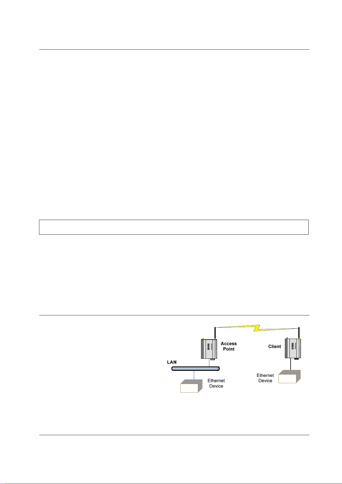
The first diagram shows a connection between two Ethernet
devices using 245U-E ethernet modems. In this example one
245U-E is configured as an Access Point and the other as a
Client - the Access Point can be connected.
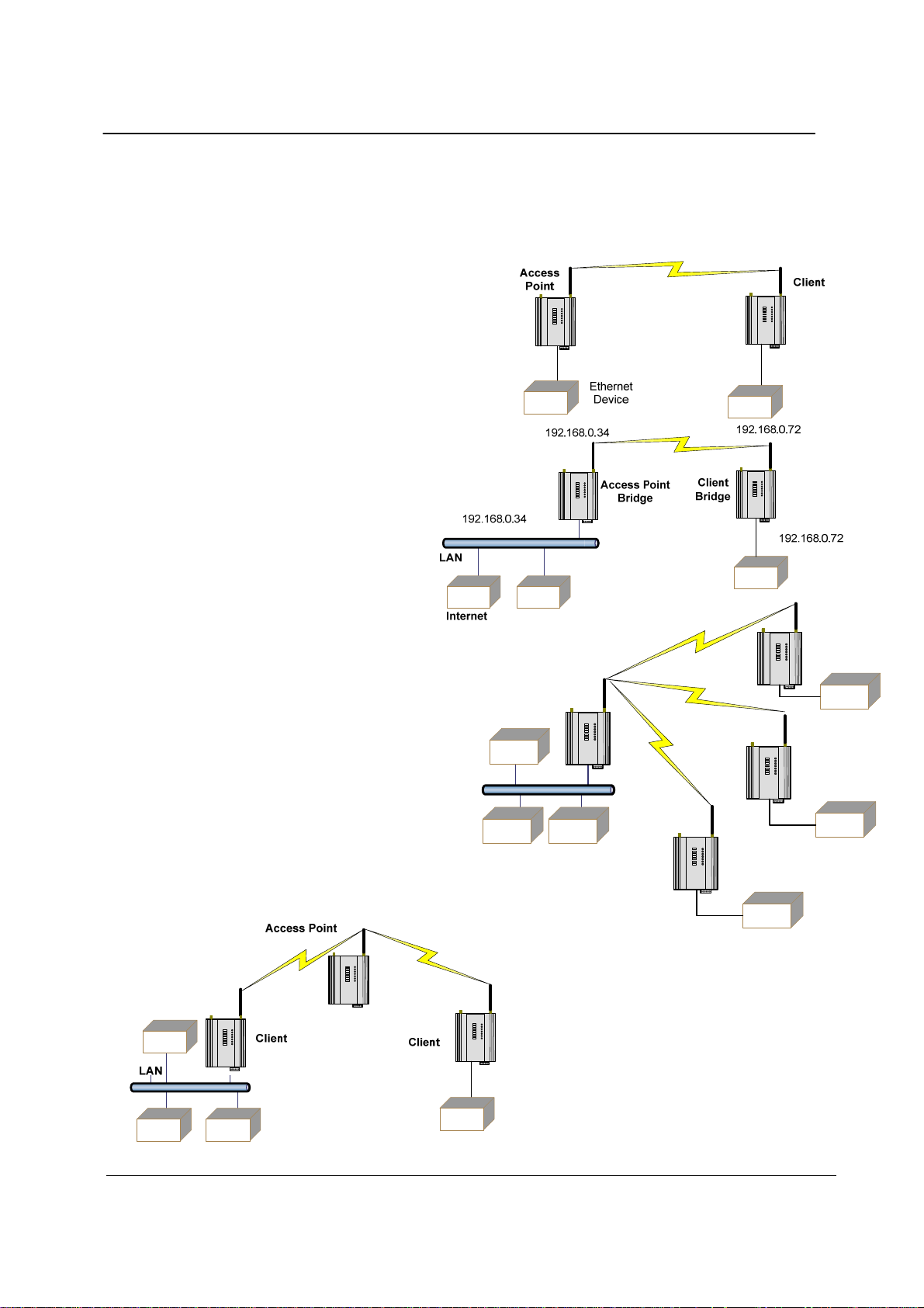
The second diagram shows an existing LAN
being extended using 245U-E’s. In this
example, the Access Point should be
configured at the LAN end - although the
wireless link will still work if the Client is at
the LAN end.
An Access Point can connect to multiple Clients.
In this case, the Access Point should be the
“central” unit.
Access
Point
LAN
An Access Point could be used as a “Repeater”
unit to connect two 245U-E Clients, which do not
have direct reliable radio paths.
There is no “Special” repeater module, any 245UE can be a repeater and at the same time, can be
Ethernet Devices
Client
connected to an Ethernet devices or on a LAN
Client
Client
Multiple Access Points can be set-up in a “mesh”
network to provide multiple repeaters.
Man_245UE_V1.5.doc Page 9
245U-E Wireless Ethernet User Manual
Bridge vs Router
Each 245U-E is configured with an IP address for the Ethernet side, an d another for the wireless side.
A Bridge connects devices within the same
Ethernet network - for example, extending an
existing Ethernet LAN. For a Bridge, the IP
address for the wireless side is the same as the
Ethernet side.
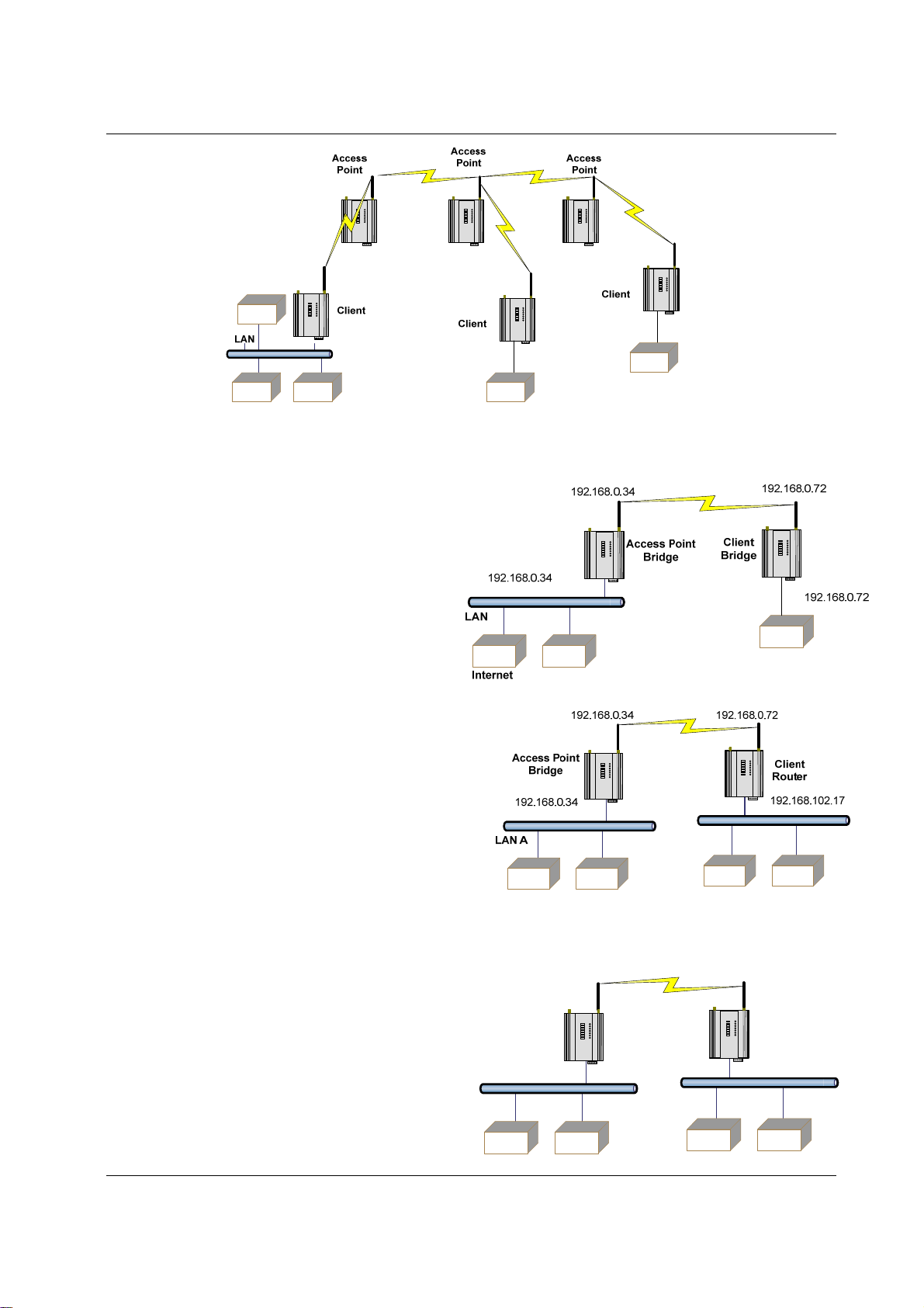
A Router connects devices on different LAN’s.
The IP addresses for the Ethernet and wireless sides are
different. In this example, the wireless link is part of
LAN A, with the Client unit acting as a Router between
LAN A and LAN B.
Alternately, the Access Point could be configured as a Router - the wireless link is then part of LAN B.
192.168.102.54
192.168.102.53
Access Point
Router
192.168.0.34
Client
Bridge
192.168.102.17
LAN A
LAN B
Page 10 Dec 2009
Chapter One 245U-E Wireless Ethernet
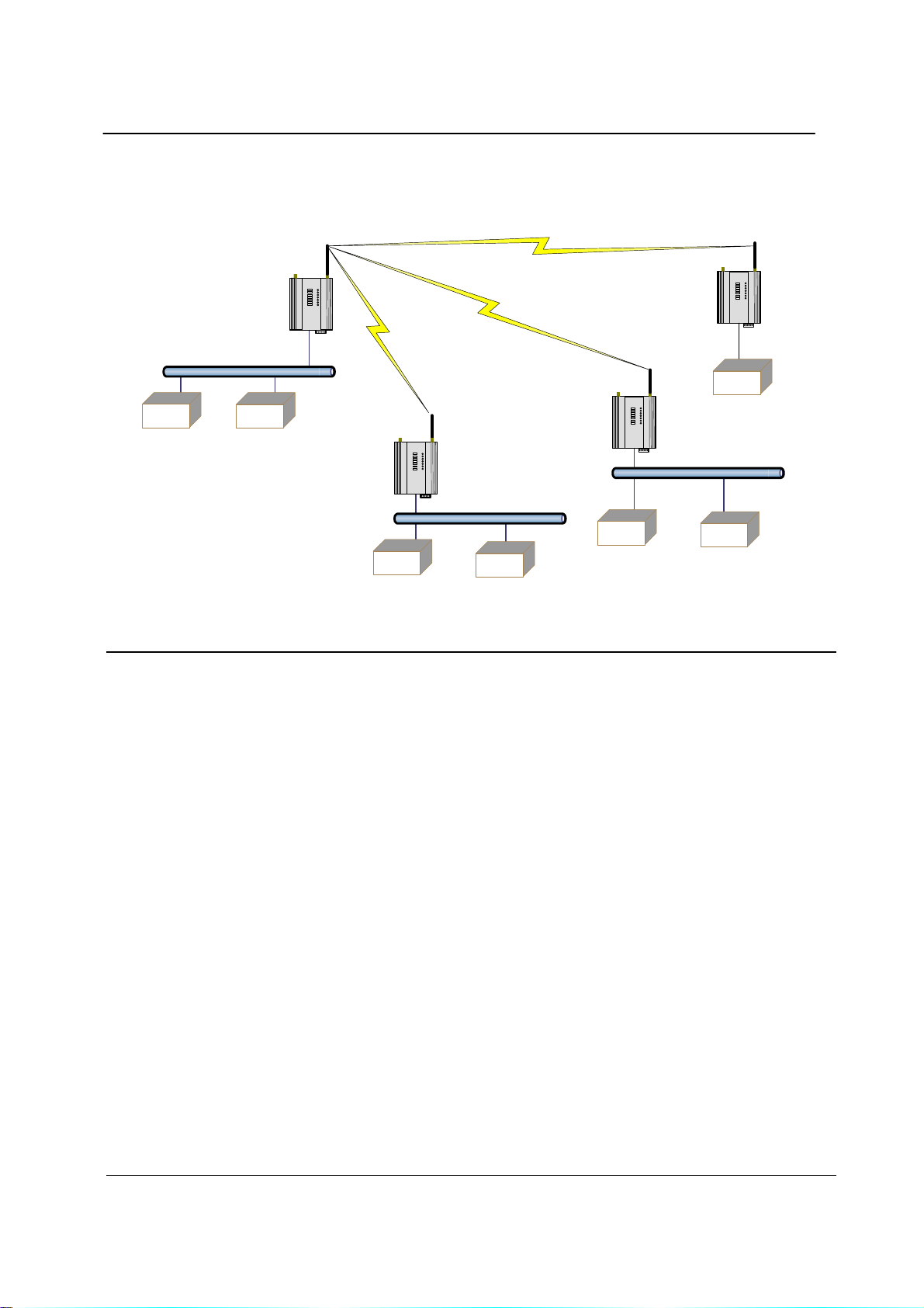
If more than two routers are required within the same radio network, then routing rules may need to be configured (refer
section “3.13 Routing Rules” for further details). There is no limit to the number of Bridges in the same network - although
there is a limit of 128 Client units linked to any one Access Point.
192.168.0.72
192.168.0.34
Client
Access Point
Bridge
Bridge
LAN A
192.168.0.34
Client
Router
192.168.0.74
192.168.109.40
192.168.0.73
Client
Router
LAN B
192.168.0.72
192.168.102.17
LAN C
1.2 Getting Started Quickly
Most applications for the 245U-E require little configuration. The 245U-E has many sophisticated features, however if
you don’t require these features, this section will allow you to configure the units quickly.
First, read Chapter 2, “Installation”. The 245U-E requires an antenna an d a power supply.
Power the 245U-E and make an Ethernet connection to your PC (for further information on how to do this, refer to
section 3.2 “Configuring the Unit for the first time”)
Set the 245U-E address settings as per section 3.2 “Configu ring the Unit for the first time”
Save the configuration - the 245U-E is now ready to use.
Before installing the 245U-E, bench test the system. It is a lot easier to locate problems when the equipment is all
together.
There are other configuration settings, which may or may not improve the operation of the system. For details on these
settings, refer to section 3.0 “Start-up”.
Man_245UE_V1.5.doc Page 11

245U-E Wireless Ethernet User Manual
Chapter Two INSTALLATION
2.0 General
The 245U-E modules are housed in a rugged aluminium case, suitable for DIN-rail mounting. Terminals will accept
wires up to 2.5 mm
All connections to the module must be SELV (Safety Extra Low Voltage). Normal 110-250V mains supply must
not be connected to any terminal of the 245U-E module. Refer to Section 2.3 Power Supply.
Before installing a new system, it is preferable to bench test the complete system. Configuration problems are easier to
recognize when the system units are adjacent. Following installation, the most common problem is poor
communications caused by incorrectly installed antennas, or radio interference on the same channel, or the radio path
being inadequate. If the radio path is a problem (i.e. path too long, or obstructed), a higher performance antennas or a
higher mounting point for the antenna may rectify the problem. Alternately, use an intermediate 245U-E Module as a
repeater.
The 245U-E Installation Guide provides an installation drawing appropriate to most applications. Further information
is detailed below.
Each 245U-E module should be effectively earthed via the "GND" terminal on the back of the module - this is to
ensure that the surge protection circuits inside are effective.
2
(12 gauge) in size.
2.1 Antenna Installation
The 245U-E module will operate reliably over large distances however the achievable distances will vary with the
application, radio model, type and location of antennas, the degree of radio interference, and obstructions (such as
buildings or trees) to the radio path.
The maximum range achievable depends on the radio model, the regulated RF power permitted in your country, and
whether you use separate transmit and receive antennas.
• If using a 245U-E-G (2.4GHz) with a single antenna, 10 km (6 miles) can be achieved in USA, Canada and
Australia (4W EIRP) and 2km in Europe (100mW EIRP).
• If using a 245U-E-A (5 GHz) with a single antenna, 5 km (3 miles) can be achieved in USA, Canada and
Australia (1W EIRP) and 3km in Europe (500mW EIRP) however more care is needed in selecting antenna’s,
coax as well as radio paths need to be complete line of site (No obstruction what so ever).
To achieve the maximum transmission distance, the antennas should be raised above intermediate obstructions so the
radio path is true “line of sight”. The modules will operate reliably with some obstruction of the radio path, although
the reliable distance will be reduced. Obstructions which are close to either antenna will have more of a blocking affect
than obstructions in the middle of the radio path.
The 245U-E modules provide a diagnostic feature which displays the radio signal strength of transmissions (refer
Chapter 4 “Diagnostics”).
Line-of-sight paths are only necessary to obtain the maximum range. Obstructions will reduce the range, however may
not prevent a reliable path. A larger amount of obstruction can be tolerated for shorter distances. For short distances, it
is possible to mount the antennas inside buildings. An obstructed path requires testing to determine if the path will be
reliable - refer the section 6 of this manual.
Where it is not possible to achieve reliable communications between two 245U-E modules, then a third 245U-E
module may be used to receive the message and re-transmit it. This module is referred to as a repeater. This module
may also have a host device connected to it.
The 245U-E unit has two antenna connections at the top of the module, allowing for two antennas to be fitted to the
module. The left connector (looking at the front) labeled “RX” by default is connected only to the internal wir eless
receiver and the right connector labeled TX/RX is connected to both the transmitter and receiver (**Note).
Note: Each antenna port has the option to enable /disable the Receive and Transmit
functionality by selecting Receive and Transmit Diversity on the radio page. When only one
antenna is used, it must be connected to the TX/RX connector.
Dual Antenna Installations
Most installations in industrial plants and factories use single omni-directional antennas. Installations can suffer from “
Page 12 Dec 2009
Chapter Two 245U-E Wireless Eth ernet
multi-path fading” effects where multiple reflected radio signals adversely affect the signal strength. This can be
checked by moving the antenna a short distance (10 cm or 4 inches) - if the signal increases significantly then there are
multi-path effects.
In a “static” installation, where the radio path is not changing, moving an antenna to the position of maximum signal
solves this problem. However where the radio path changes because the 245U-E is mounted on moving equipment, or
if there is moving equipment in the area, then the solution is to use two antennas. Because the two connectors are
separated, the RF signal at each connector will be different in the presence of multi-path fading. The 245U-E un it will
automatically select the higher RF signal provided RX diversity has been enabled on radio config page.
Note that directional antennas are not normally used in plant and factory installations.
Another reason for using dual antenna is to improve the receiver gain. All countries have a limit on the amount of
transmitted power (from the module) and radiated power (from the antenna). In the US this is 1 Watt Transmit power
and 4 watts EIRP (Effective Isotropic Radiated Power)
A general rule of thumb when working with dB and Power is to remember that doubling the Power is a 3dB gain.
Therefore if we add a 6dB gain antenna to the 1 Watt transmitter we can boost the EIRP to 4 Watts (1 watt
Line-of-sight installations
In longer line-of-sight installations, the range may be increased by using a high gain antenna on the TX/RX co nnector.
However, the gain should not cause the effective radiated power (ERP) to exceed the permitted value. A second higher
gain antenna can be connected to the RX connector without affecting ERP - this will increase the operating range
provided any interference in the direction of the link is low.
Antennas
Antennas can be either connected directly to the module connectors or connected via 50 ohm coaxial cable (e.g. RG58
Cellfoil or RG213) terminated with a male SMA coaxial connector. The higher the antenna is mounted, the greater the
transmission range will be, however as the length of coaxial cable increases so do cable losses.
The net gain of an antenna/cable configuration is the gain of the antenna (in dBi) less the loss in the coaxial cable (in
dB). The maximum net gain of the antenna/cable configuration connected to the TX/RX connector is 0dB in Europe
(100mW ERP). In USA, Canada and Australia (4W ERP), the maximum gain is 10dB for the 245U-E-400 or 16dB for
the 245U-E-100. There is no gain restriction for antennas connected to the RX connector.
(*) 20dB attenuator m ust be fitted if radio distance is less than 33ft (10m).
Antenna 245U-E-G Gain (dBi) 245U-E-A Gain (dBi)
Dipole 2 dBi 6 dBi
Collinear 5 or 10 dBi 10 dBi
Directional 18 dBi 10 – 20 dBi
Cable Loss dB per 30 m / 100 ft dB per 30 m / 100 ft
RG58 Cellfoil -17 dB -24.5 dB
RG213 -16.2 dB -28.6 dB
LDF4-50 -3.6 dB -5.5 dB
The net gain of the antenna/cable configuration is determined by adding the antenna gain and the cable loss.
For example, if using the 245U-E-G a 10dBi antenna (7.8dBd) with 10 meters of
Cellfoil (-5.6dB) has a net gain of 2.2dB (7.8dB – 5.6dB).
Installation tips
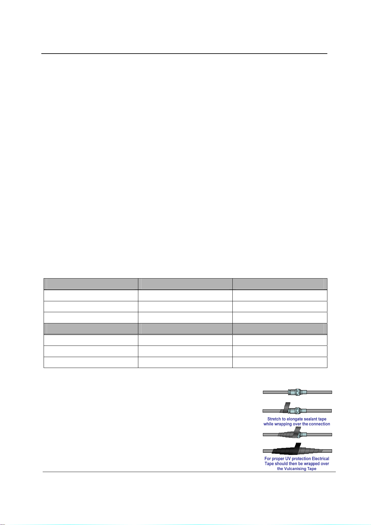
Connections between the antenna and coaxial cable should be carefully taped to
prevent ingress of moisture. Moisture ingress in the coaxial cable is a common cause
for problems with radio systems, as it greatly increases the radio losses. We
recommend that the connection be taped, firstly with a layer of PVC Tape, then with
a vulcanizing tape such as “3M 23 tape”, and finally with another layer of PVC UV
Stabilized insulating tape. The first layer of tape allows the joint to be easily
inspected when trouble shooting as the vulcanizing seal can be easily removed.
Where antennas are mounted on elevated masts, the masts should be effectively
earthed to avoid lightning surges. For high lightning risk areas, surge suppression
Man_245UE_V1.5.doc Page 13
245U-E Wireless Ethernet User Manual
devices between the module and the antenna are recommended. If the antenna is not already shielded from lightning
strike by an adjacent earthed structure, a lightning rod may be installed above the antenna to provide shielding.
Dipole and Collinear antennas
A dipole or collinear antenna transmits the same amount of radio power in all directions - as such that are easy to
install and use. The dipole antenna with integral 15 ft (5m) cable does not require any additional coaxial cable;
however a cable must be used with the collinear antennas.
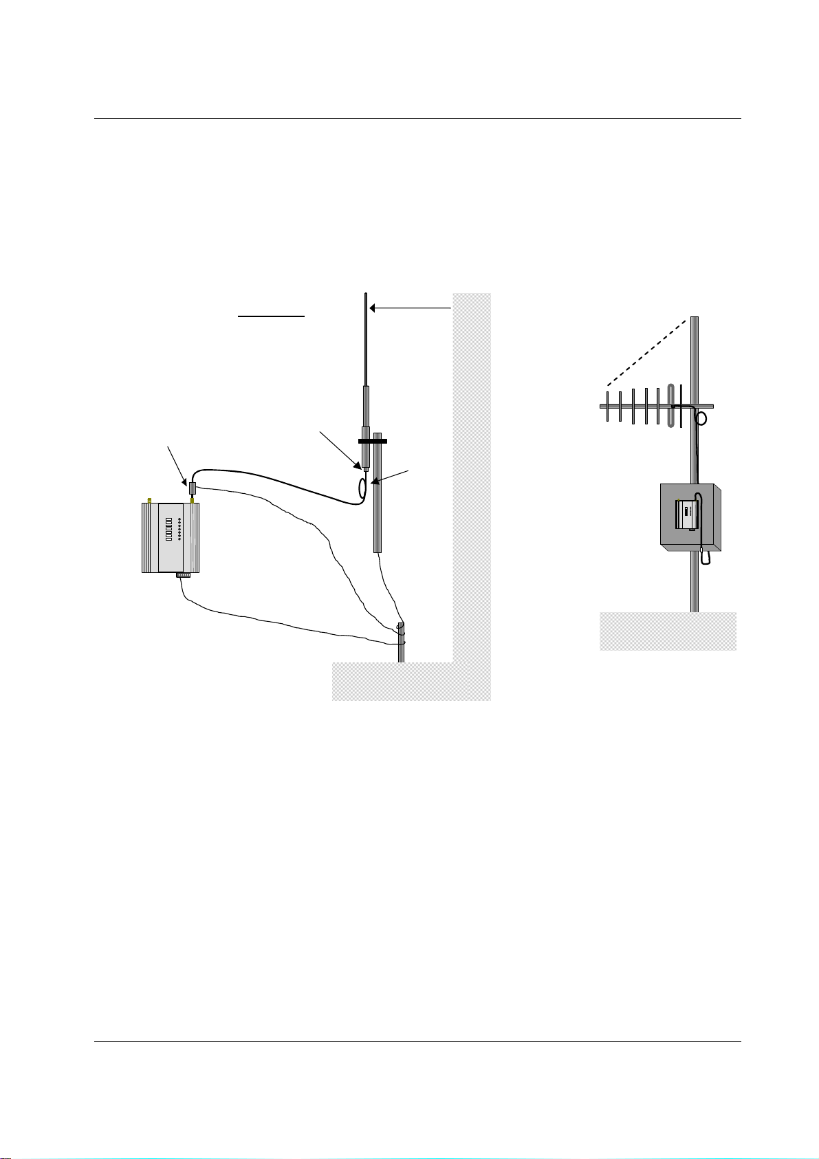
Collinear and dipole antennas should be mounted vertically, preferably 1 wavelength away (see drawing below for
distances) from a wall or mast and at least 3ft (1m) from the radio module to obtain maximum range.
o
45
Directional
Antenna
SURGE
ARRESTOR
(OPTIONAL)
Wavelengths
900 MHz = 330 mm (1')
2.4 GHz = 130 mm (5")
5 GHz = 60 mm (3")
WEATHERPROOF
CONNECTORS WITH
“3M 23” TAPE
COAXIAL CABLE
1 wavelength
COLINEAR
ANTENNA
STRESS RELIEF
LOOP
MAST
MODEM
PROVIDE GOOD GROUND
CONNECTION TO MAST,
MODULE AND SURGE
GND
ARRESTOR
IF GROUND CONDITIONS
ARE POOR, INSTALL MORE
THAN ONE STAKE
Directional antennas.
Directional antennas can be
a Yagi antenna with a main beam and orthogonal elements, or
a directional radome, which is cylindrical in shape, or
a parabolic antenna.
A directional antenna provides high gain in the forward direction, but lower gain in oth er directions. This may be used
to compensate for coaxial cable loss for installations with marginal radio path.
Yagi antennas should be installed with the main beam horizontal, pointing in the forward direction. If the Yagi is
transmitting to a vertically mounted omni-directional antenna, then the Yagi elements should be vertical. If the Yagi is
transmitting to another Yagi, then the elements at each end of the wireless link need to in the same plane (horizontal or
vertical).
Directional radomes should be installed with the central beam horizontal and must be pointed exactly in the direction of
transmission to benefit from the gain of the antenna. Parabolic antennas should be mounted as per the manufacturer’s
instructions, with the parabolic grid at the “back” and the radiating element pointing in the direction of the
transmission.
Ensure that the antenna mounting bracket is well connected to “ground/earth”.
Page 14 Dec 2009
Chapter Two 245U-E Wireless Eth ernet
_
2.2 Power Supply
The 245U-E module can be powered from a 9 - 30VDC power supply. The
power supply should be rated at 1 Amp. The positive
side of the supply must not be connected to earth.
supply negative is connected to the unit case
internally. The DC supply may be a floating
supply or negatively grounded.
The power requirements of the 245U-E unit are shown in the following table
Quiescent
TX @100mW
TX @ 400mW
A Ground Terminal is provided on the back of the module. This Terminal should be connected to the Main Ground
point of the installation in order to provide efficient surge protection f or the module (refer to the Installation Diagram)
12VDC 24VDC 12VDC 24VDC
290mA 150mA 300mA 160mA
310mA 170mA 370mA 190mA
340mA 180mA 410mA 210mA
The
9 - 30
VDC
+
245U-E-G 245U-E-A
B
RS485
A
-
SUPPLY
+
COM
DIO
MODEM
2.3 Serial Connections
RS232 Serial Port
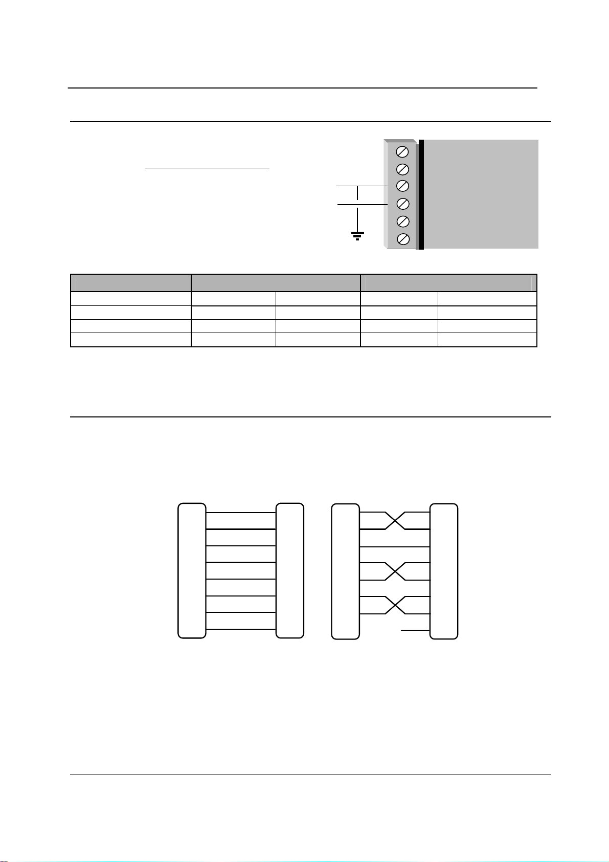
The serial port is a 9 pin DB9 female and provides for connection to a host device as well as a PC terminal for
configuration, field testing and for factory testing. Communication is via standard RS232 signals. The 2 45U-E is
configured as DCE equipment with the pinouts detailed below.
Hardware handshaking using the CTS/RTS lines is provided. The CTS/RTS lines may be used to reflect the status of
the local unit’s input buffer. The 245U-E does not support XON/XOFF.
Example cable drawings for connection to a DTE host (a PC) or another DCE hosts (or modem) are detailed above.
RD
TD
SG
RTS
CTS
DSR
DTR
DCD
DB9
MALE
2
3
5
7
8
6
4
1
2
RD
3
TD
5
SG
7
RTS
8
CTS
6
DSR
4
DTR
1
DCD
DCE HOSTMODEM
DB9
FEMALE
RD
TD
SG
RTS
CTS
DSR
DTR
DCD
MODEM
DB9
MALE
2
3
5
7
8
6
4
1
2
RD
3
TD
5
SG
7
RTS
8
CTS
6
DSR
4
DTR
1
DCD
DCE HOST
DB9
MALE
Man_245UE_V1.5.doc Page 15
245U-E Wireless Ethernet User Manual
DB9 Connector Pinouts
Pin Name Direction Function
1 DCD Out
2 RD Out
3 TD In
4 DTR In
5 SG
6 DSR Out
7 RTS In
8 CTS Out
9 RI
Data carrier detect
Transmit Data – Serial Data Output (from DCE to DTE)
Receive Data – Serial Data Input (from DTE to DCE)
Data Terminal Ready
Signal Ground
Data Set Ready - always high w hen uni t is pow ered o n.
Request to Send
Clear to send
Ring indicator
RS485 Serial Port
The RS485 po r t pro v ide s f o r commu nicati o n between the 245U-E unit and its hos t devic e u sing a mu l ti- d r o p cab le. U p to
32 devices may be connected in each multi-drop network.
As the RS485 communication medium is shared, only one of the units on the RS485 cable may send data at any one
time. Thus, communication protocols based on the RS-485 standard require some type of arbitration.
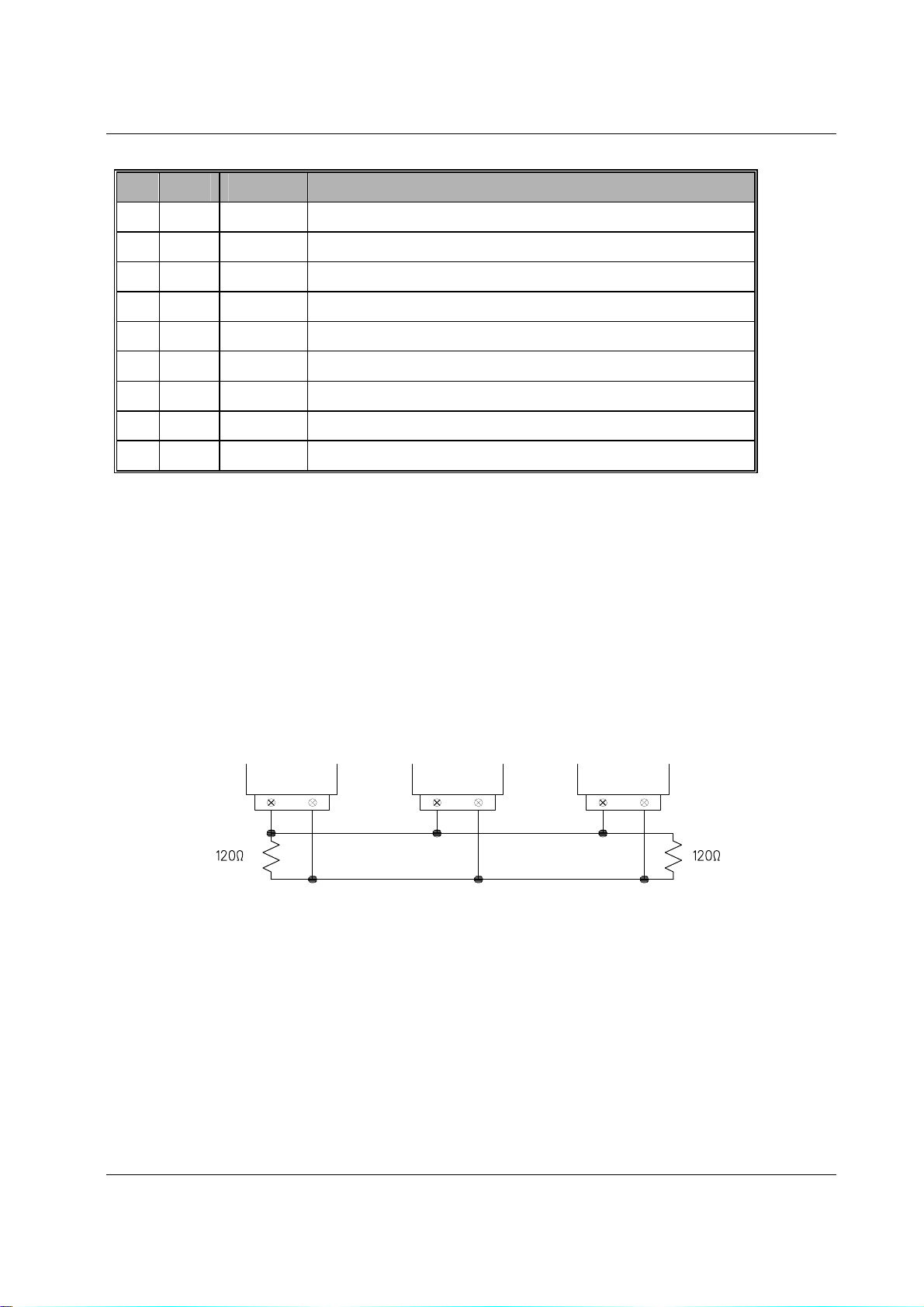
RS485 is a balanced, differential standard but it is recommended that shielded, twisted pair cable be used to
interconnect modules to reduce potential RFI. It is important to maintain the polarity of the two RS485 wires. An
RS485 network should be wired as indicated in the diagram below and terminated at each end of the network with a
120-ohm resistor. On-board 120-ohm resistors are provided and may be engaged by operating the single DIP switch in
the end plate next to the RS485 terminals. The DIP switch should be in the “1” or “on” position to connect the resistor.
If the module is not at one end of the RS485 cable, the switch should be off.
HOST MODEM HOST
RS485 CONNECTIONS
Shorter runs of 485 cable may not require the termination resistors to be enabled.
Page 16 Dec 2009

Chapter Two 245U-E Wireless Eth ernet
DIP SWITCH
ETHERNET
DEFAULT DIP
SWITCH
RS232
RS485
SUPPLY
FOR 120Ω
DIO
Man_245UE_V1.5.doc Page 17
245U-E Wireless Ethernet User Manual
V
_
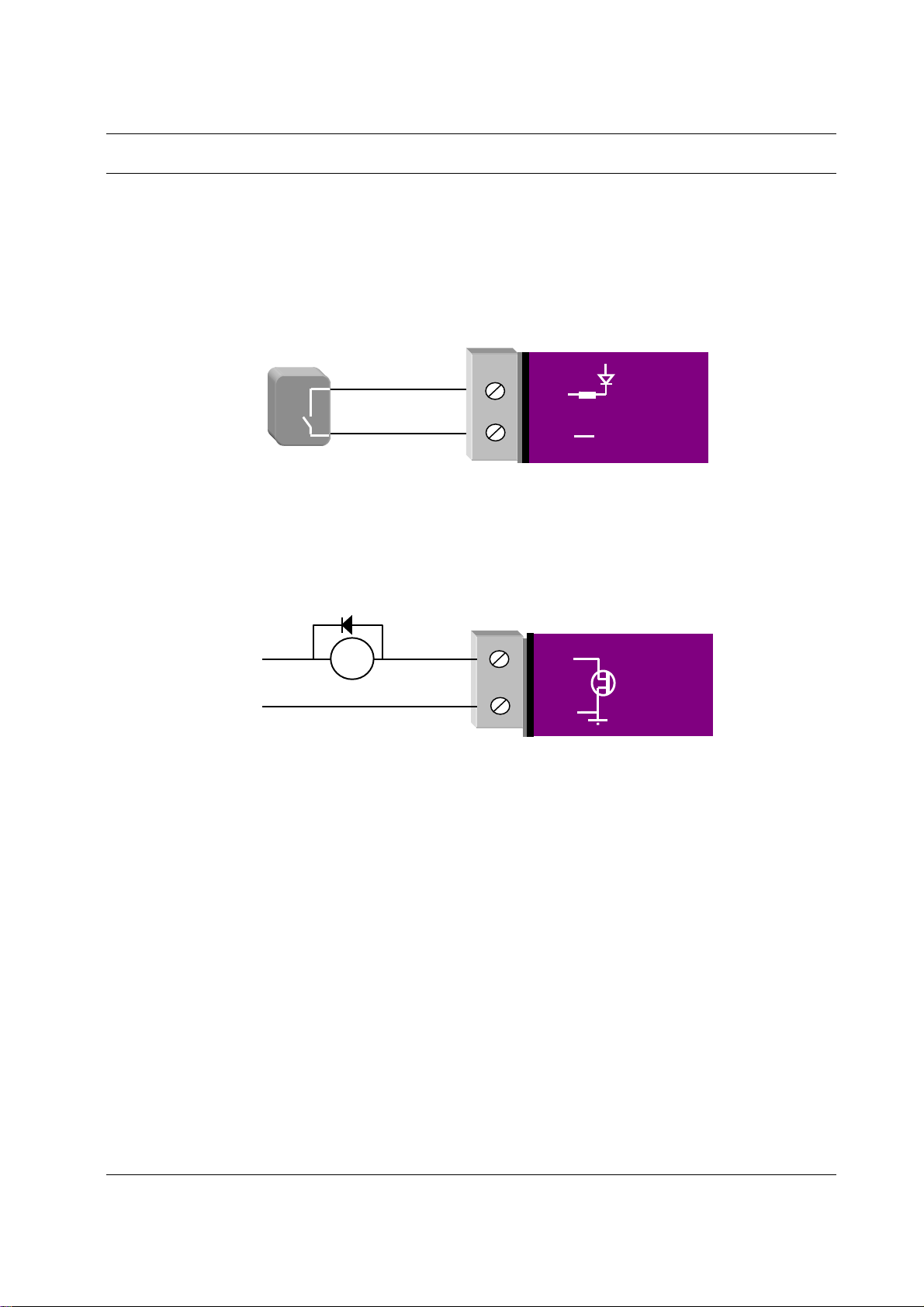
2.4 Discrete (Digital) Input/Output
The 245U-E has one on-board discrete/digital I/O channel. This channel can act as either a discrete input or discrete
output. It can be monitored, or set remotely, or alternatively used to output a communications alarm status.
If used as an “input”, the I/O channel is suitable for voltage free contacts (such as mechanical switches) or NPN
transistor devices (such as electronic proximity switches). PNP transistor devices are not suitable. Contact wetting
current of approximately 5mA is provided to maintain reliable operation of driving relays.
The digital input is connected between the "DIO" terminal and common “COM". The I/O circuit includes a LED
indicator which is lit GREEN when the digital input is active, that is, when the input circuit is closed. Provided the
resistance of the switching device is less than 200 ohms, the device will be able to activate the digital input.
DIO
Voltage-free
contact input
The I/O channel may also be used as a discrete output. The digital outputs are transistor switched DC signals, FET
output to common rated at 30VDC 500 mA.
The output circuit is connected to the "DIO" terminal. The digital output circuit includes a LED indicator which is lit
RED when the digital output is active.
Max 30VDC
0.5A
+
DC
Load
GND
DIO
GND
V+
-
MODEM
MODEM
Page 18 Dec 2009

Chapter Three 245U-E Wireless Eth ernet
Chapter Three OPERATION
3.0 Start-up
“Access Point” Start-up (245U-E-G)
When an Access Point (AP) unit starts up it checks to see if the Channel selection is set to “Auto” and if so will scan all
available channels, pick the quietest then begin transmitting periodic messages, called beacons, if it is configured with
a fixed channel it will immediately begins sending beacons, on the configured channel.
Beacons include information that a Client may examine in order to identify if the Access Point is suitable for link
establishment. Clients will only attempt to establish a link with an Access Point whose beacon indicates a matching
SSID. Access Points do not initiate link establishment.
“Access Point” Start-up (245U-E-A)
If the modem is configured to use “DFS” then it will behave slightly different, as it needs to comply with DFS
regulations.
When an Access Point starts up it will scan all available channels from the selected groups and then select the quietest
similar to the 245U-E-G. It will then go into a scan mode for 60 seconds where it listens for any Radar signals.
If a radar signal is detected it will flag the channel as being unavailable (Channel will stay unavailable for 30 minutes)
and then pick another random channel and go through the same scanning process until a radar free channel be comes
available.
“Client” Start-up
When a Client powers up, it scans for beacons from Access Points. While a link is not established, the Client cyclically
scans all available channels for a suitable Access Point. The Client will attempt to establish a link with an Access Point
only if it has matching SSID, Encryption method, etc. and other compatible capabilities as indicated by the beacon. If
more than one suitable Access Point is discovered, the client will attempt to establish a link with the Access Point that
has the strongest radio signal.
Link Establishment
Once a Client identifies a suitable Access Point for link establishment it attempts to establish a link using a two step
process – “Authentication” and “Association”. During Authentication the Client and Access Point check if their
configurations permit them to establish a link. Once the Client has been authenticated, it will then request an
Association to establish a link.
Status of the wireless link is indicated via the TX/LINK LED. For an Access Point, the TX/LINK LED will be OFF
while no links have been established. Once one or more links have been established, the TX/LINK LED is on GREEN.
For a Client, the Link LED will reflect the connection status to an Access Point. Link status is also displayed on the
“Connectivity” page of the web interface.
After the link is established, data may be transferred in both directions. The Access Point will act as a master-unit and
will control the flow of data to the Clients linked to it. Clients can only transmit data to the AP to which they are
connected. When a Client transfers data to another Client, it first transmits the data to the AP, which then forwards the
data to the destined Client.
Presence of a “link” does not mean that the connected unit is authorized to communicate
over radio. If the encryption keys are incorrect between units in the same system, or a
dissimilar encryption scheme is configured, the LINK led will light, however data cannot be
passed over the wireless network.
A maximum of 127 Clients may be linked to an Access Point.
How a Link connection is lost
The Access Point refreshes the link status with a Client every time a message is received from that Client. If nothing is
received from a Client for a period of 120 seconds, the Access Point sends a “link-check” message. If ther e is no
response to the link-check a De-authenticate message is sent and the link is dropped.
man_245UE_V1.5.doc Page 19

245U-E Wireless Ethernet User Manual
A Client monitors beacon messages from an Access Point to determine whether the link is still present. If the Client can
no longer receive beacons from the Access Point it assumes the AP is out-of-range and the link is dropped. Whenever a
Client is not connected to an AP, it will cyclically scan all available channels for a suitable AP.
Roaming Clients
Clients can roam within a system however if the link to the Access Point fails or the radio signal level becomes too
weak it will scan for beacons and connect to an Access Point (provided the SSID and any Encryption methods, keys,
etc are compatible). If there are multiple Access Points it will select the connection with the best signal level. This
functionality permits a client to have mobility whilst maintaining a link with the most suitable AP.
LED Indication
The following table details the status of the indicating LEDs on the front panel under normal operating conditions.
LED Indicator Condition Meaning
OK GREEN Normal Operation
OK Flashing RED / GREEN Module Boot Sequence
Radio RX GREEN flash Radio receiving data (Good Signal Strength)
Radio RX RED flash Radio receiving data (Low Signal strength)
TX/LINK GREEN Radio Connection Established
TX/LINK RED Flash Radio Transmitting
RS-232 GREEN flash Data sent from RS-232 Serial Port
RS-232 RED flash Data received to RS-232 Serial Port
LAN ON Link Established on Ethernet port
LAN Flash Activity on Ethernet port.
RS-485 GREEN flash Data sent from RS-485 Serial Port
RS-485 RED flash Data received to RS-485 Serial Port
DIO GREEN Digital Input is grounded.
DIO RED Digital Output is active
DIO Off
Digital Output OFF
and Input is open circuit.
The Ethernet RJ45 port incorporates two indication LEDs. The LINK LED comes on when there is a connection on the
Ethernet port, and will blink off briefly when activity is detected on the Ethernet Port. The 10 0MB LED indicates that
the connection is at 100 MBit/Sec. The 100MB LED will be off for 10MB/Sec connection.
Other conditions indicating a fault are described in Chapter Four - DIAGNOSTICS.
Page 20 Dec 2009
Chapter Three 245U-E Wireless Eth ernet
3.1 Selecting a Channel
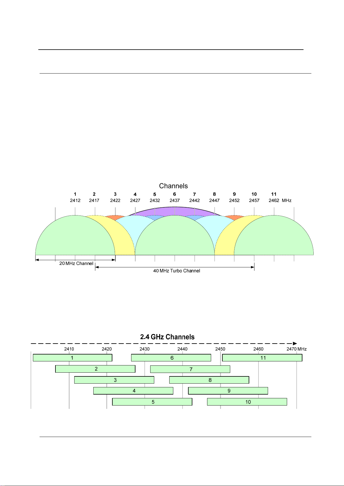
802.11b/g (2.4GHz)
The 245U-E-G conforms to the IEEE 802.11b/g Wireless LAN specification. The 245U-E-G supports 13 radio
channels, in the range 2412MHz to 2462MHz each channel is 22MHz wide with a channel separation of 5M. Only one
of these channels is used for a connection. The desired channel is selected and co nfigured at the Access Point, and is
then used for all beacon transmissions and connections.
Clients scan all 13 channels for a suitable Access Point and then adopt the same channel as the AP when a connection
is established.
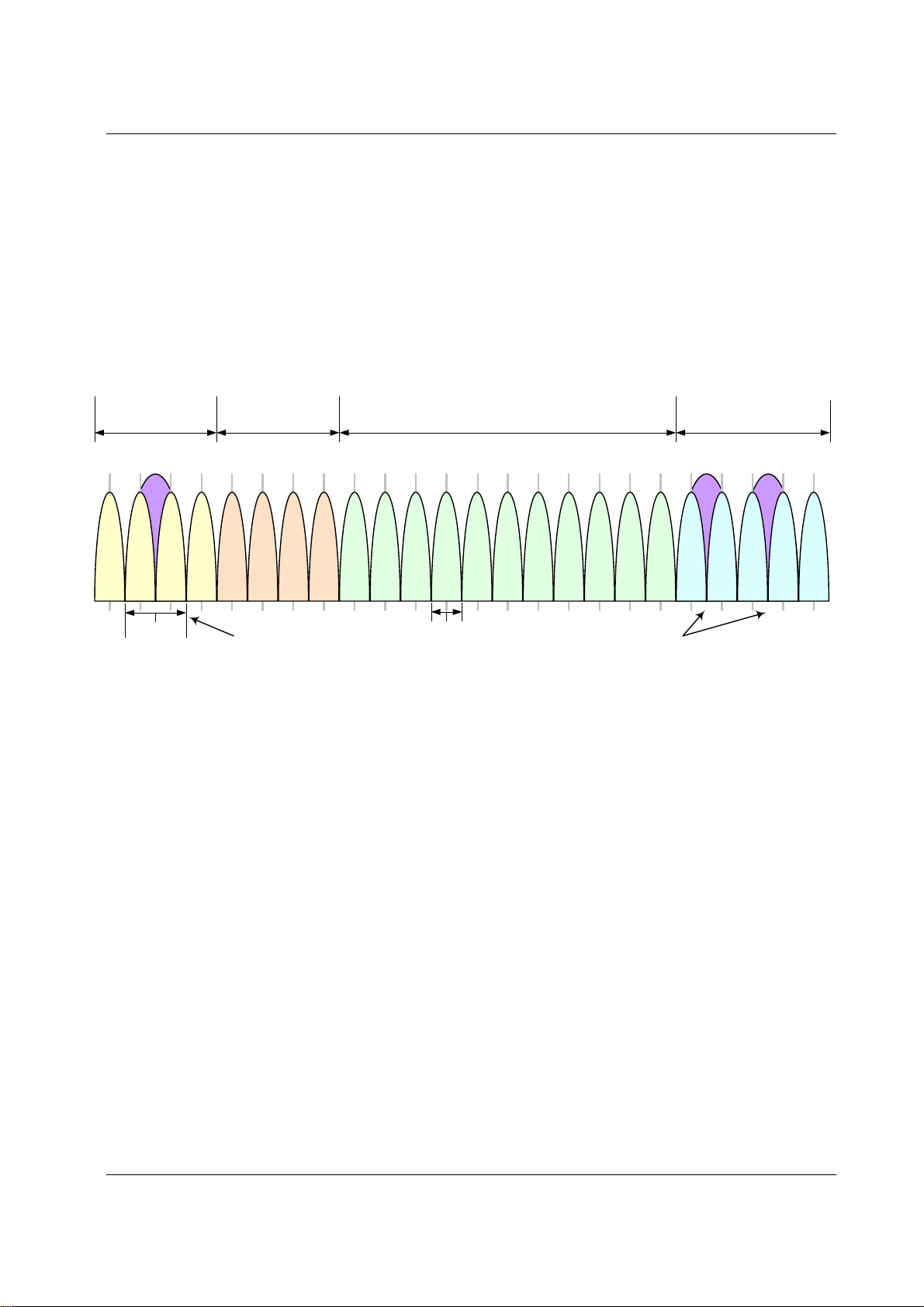
Hence, the channels overlap. The following diagram shows the RF energy distribution for an 802.11b/g transmission:
Most of the energy is transmitted on the 22 MHz wide channel configured, however some energy will be transmitted on
the channels either side.
If we ignore the side lobes and consider each 802.11b/g message as a 22MHz wide transmission, then the following
diagram represents how transmissions in each channel overlaps.
If there is more than one 802.11 AP within the same wireless range, then it is important that the AP’s are on channels
as far apart as possible.
If there are only two AP’s, then set them to 1 and 11. If there are three, set them to 1, 6, and 11.
It is also important that correct channel is selected for region. Channels 1 to 11 are approved for North America (FCC),
Europe (ETSI), Canada (IC) and Australia (ACMA). Refer to your regional regulatory author ity for which rad io
channels are approved for use.
man_245UE_V1.5.doc Page 21
245U-E Wireless Ethernet User Manual
802.11a (5GHz)
The 245U-E-A utilizes frequency bands within the range of 5.15 GHz and 5.825 GHz. This is broken into 4 distinct UNII bands and each region (EU, US, AUS, NZ, etc) have their own power and operational constraints, see Appendix C
for more details.
The example below shows the US power and operational constraints
•
“Group 1”: 5.15-5.25GHz @ 50mW
“Group 2”: 5.25-5.35GHz @ 250mW to 1 Watt
•
“Group 3”: 5.47-5.725 GHz @ 250mW to 1 Watt
•
•
“Group 4”: 5.725-5.825GHz @ 1Watt
Each frequency band has certain limitations on the amount of radiated power that it can output as well as whether the
band uses what is called “Dynamic Frequency Selection” (DFS), explained below.
5 GHz Channels
Group 1
5.15-5.25 GHz
44 52 60 100 10836 48 56 64 10440 120 128 136 149 157112 124 132 140 153116 157161
5220 5260 5300 5500 55405180 5240 5280 5320 55205200 5600 5640 5680 5745 5785
Group 2
5.25-5.35 GHz
Group 3
5.47-5.725 GHz
5560 5620 5660 5700 57655580 5805 5825
Group 4
5.725-5.825 GHz
MHz
40MHz
108Mbps
Turbo Channel 41
20MHz
54Mbps
Turbo Channels
152 & 160
Dynamic Frequency Selection (DFS)
Because of the push within the 802.11a market to open up new spectrum for unlicensed radio a mechanism called
“Dynamic Frequency Selection” needed to be developed so that the 802.11 Wifi could coexist with existing military
and telecommunication radar systems.
Access points with 5GHz radios comply with regulations that require radio devices to use Dynamic Frequency
Selection (DFS), which can detect radar signals and avoid interfering with them by automatically scanning and then
selecting another channel or band.
When DFS is enabled, the Access Point (master device) goes through the following steps:
The master device that initiates communications selects a channel and monitors that channel for potential radar
1.
interference for a minimum listening time of 60sec (channel availability check time). No transmissions can
occur during this period.
2.
If interference is detected then the system has to go and select another channel and repeat the channel
availability check on the new channel (the original channel is added to a list of channels with radar).
Once a channel has been selected and passes the channel availability check the network starts to use that channel.
3.
While using the channel the network’s master device continuously monitors for potential interference from a
4.
radar source (this is referred to as “in-service monitoring”). If interference is detected then th e network master
device issues commands to all other in-network devices to cease transmissions. The channel is added to the
list of channels with radar.
5.
The master device then selects a new channel (one that is not on the radar list).
6.
A channel that has been flagged as containing a radar signal, either by a channel availability check or b y in-
service monitoring, is subject to a 30 min non-occupancy period where it cannot be used by the device in
order to protect scanning radars. The channel on the radar list will be purged once the non-occupancy period
has elapsed for that channel.
Page 22 Dec 2009

Chapter Three 245U-E Wireless Eth ernet
3.2 Configuring the Unit for the first time
The 245U-E has a built-in web server, containing web pages for analyzing and modifying the module’s configuration.
The configuration can be accessed using Microsoft® Internet Explor er version 7 or greater. This program is shipped
with Microsoft Windows or may be obtained freely via the Microsoft® website. If using other browsers they must be
fully compliant with IE7 SSL security.
Note: Microsoft Internet Explorer Version 6 will not load web pages due to a compatibility issue
between IE6 and SSL-security web sites.
Default Configuration
The default factory configuration of the 245U-E is
•
Client/Bridge/
•
IP address192.168.0.1XX, where XX is the last two digits of the serial number (the default IP address is shown
on the printed label on the back of the module)
•
netmask 255.255.255.0
Username is “user” and the default password is “user”
•
The 245U-E will temporarily load some factory-default settings if powered up with the Factory Default switch (on the
end-plate of the module) in SETUP position. When in SETUP mode, wireless operation is disabled. The previous
configuration remains stored in non-volatile memory and will only change if a configuration parameter is modified and
the change saved.
Do not forget to set the switch back to the RUN position and cycle power at the conclusion of
configuration for resumption of normal operation.
Accessing Configuration for the first time
Because the Default IP address is in the range 192.168.0.XXX it may not connect to you network or PC so there ar e
two methods for accessing the configuration for the first time.
Method 1 - Change your computer settings so that the configuring PC is on the same network as the 245U-E with
factory default settings. This is the preferred method and is much less complicated than the second method. You will
need a “straight-through” Ethernet cable between the PC Ethernet port and the 245U-E. Th e factor y defau lt Ethernet
address for the 245U-E is 192.168.0.1 XX where XX are the last two digits of the serial number (check the label on the
back of the module).
Method 2 - Requires temporarily changing the IP address in the 245U-E v ia an RS2 32 connection such that it is
accessible on your network without having to change your PC network settings. When connected you can change the
modem network settings to match that of your network.
Method 1 - Set PC to same network as 245U-E
Connect the Ethernet cable between unit and the PC configuring the module.
•
Set the Factory Default Switch to the SETUP position. This will always start the 245U-E with Ethernet IP address
192.168.0.1XX, subnet mask 255.255.255.0, gateway IP 192.168.0.1 and the radio disabled. Do not forget to set
the switch back to the RUN position and restart the module at the conclusion of configuration for resumption of
normal operation.
•
Power up the 245U-E module.
•
Open “Network Settings” on your PC under Control Panel. The following description is for Windows XP - earlier
Windows operating systems have similar settings.
man_245UE_V1.5.doc Page 23
245U-E Wireless Ethernet User Manual
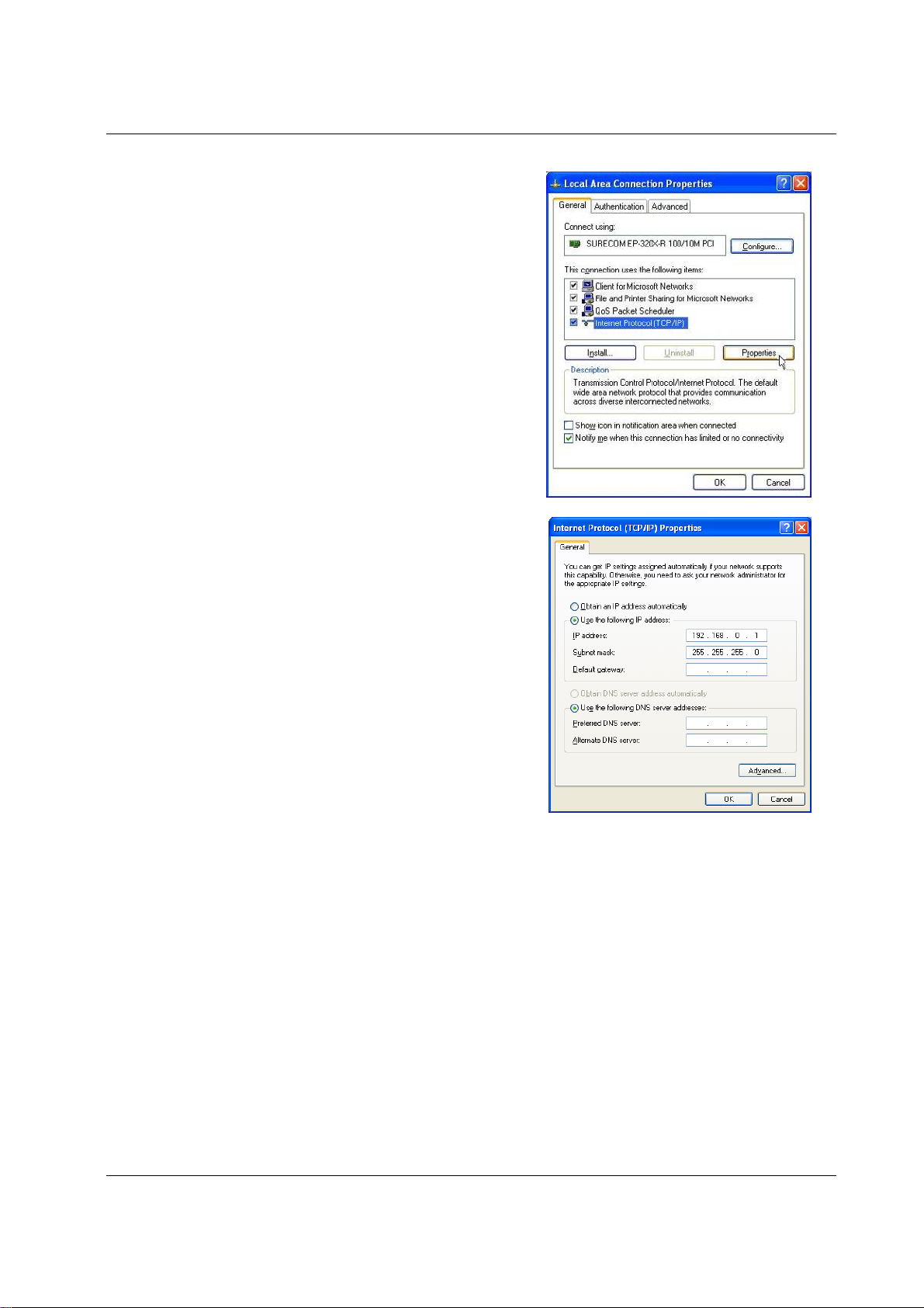
• Open “Properties” of Local Area Connection.
Select Internet Protocol (TCP/IP) and click on Properties.
•
•
On the General tab enter IP address 192.168.0.1, Subnet mask
255.255.255.0 and press “OK”
•
Open Internet Explorer and ensure that settings will allow you to
connect to the IP address selected. If the PC uses a proxy server,
ensure that Internet Explorer will bypass the Proxy Server for
local addresses.
•
This option may be modified by opening Tools -> Internet
Options -> Connections Tab -> LAN Settings->Proxy Server ->
bypass proxy for local addresses.
Enter the default IP address for the 245U-E
•
https://192.168.0.1XX where XX is the last two digits of the
serial number.
•
Enter the username “user” and default password “user”.
Page 24 Dec 2009
 Loading...