

ELPRO 215U-2, ANTSG2400-E, ANTWH2400-SMA, ANTMD2400-EL, ANTY2400-18EL User Manual
...
User Manual MN032EN
Effective October 2017
New information
215U-2 802.11
wireless I/O and gateway
Version 2.11
User Manual MN032EN
Effective October 2017
215U-2 802.11
wireless I/O and gateway
Documentation note
Eaton acquired Cooper Industries in November, 2012. “Cooper
Bussmann” may appear in some screen images within this guide.
ATTENTION
INCORRECT TERMINATION OF SUPPLY WIRES MAY CAUSE INTERNAL
DAMAGE AND WILL VOID THE WARRANTY. TO ENSURE THAT YOUR
215U-2 WIRELESS I/O AND GATEWAY ENJOYS A LONG LIFE, CHECK THIS
USER MANUAL TO VERIFY THAT ALL CONNECTIONS ARETERMINATED
CORRECTLY BEFORE TURNING ON POWER FOR THEFIRST TIME.
CAUTION
TO COMPLY WITH FCC RF EXPOSURE REQUIREMENTS IN SECTION 1.1310
OF THE FCC RULES, ANTENNAS USED WITH THIS DEVICE MUST BE
INSTALLED TO PROVIDE A SEPARATION DISTANCE OF AT LEAST 20 CM
FROM ALL PERSONS TO SATISFY RF EXPOSURE COMPLIANCE.
DO NOT OPERATE THE TRANSMITTER WHEN ANYONE IS WITHIN 20 CM OF
THE ANTENNA. ENSURE THAT THE ANTENNA IS CORRECTLY INSTALLED IN
ORDER TO SATISFY THIS SAFETY REQUIREMENT.
Avoid
•
Operate the transmitter unless all RF connectors are secure
andany open connectors are properly terminated
•
Operate the equipment near electrical blasting caps or in an
explosive atmosphere
ote:N All equipment must be properly grounded for safe operations.
All equipment should be serviced only by a qualifiedtechnician.
Manufacturer Model number Coax kit Net
ELPRO ANTMD2400-EL Includes 5 m RG58 3 dBi gain
ELPRO ANTWH2400-SMA Direct mount Unity gain
ELPRO ANTSG2400-EL CC3-SMA 5 dBi gain
ELPRO ANTY2400-18EL CC10-SMA 12 dBi gain
ELPRO ANTZ2400-EL CC3-SMA 8 dBi gain
Safety notices
Exposure to RF energy is an important safety consideration. The
FCC has adopted a safety standard for human exposure to radio
frequency electromagnetic energy emitted by FCC regulated
equipment as a result of its actions in Docket 93-62 and OET
Bulletin65 Edition 97-01.
Hazardous location notices
This equipment complies with the following standards:
•
IEC 60079-0:2012/A11:2013
•
IEC 60079-15:2010
This equipment complies with 2014/35/EU—ATEX Directive
ExnA IIC T4 Gc –40 °C ≤ Ta ≤ +70 °C.
Special conditions
This equipment is designed to be installed in anenclosure
that meets IP54.
WARNING: EXPLOSION HAZARD
DO NOT DISCONNECT EQUIPMENT UNLESS POWER HAS BEEN SWITCHED
OFF OR THE AREA IS KNOWN TO BE NON-HAZARDOUS.
FCC notice
Part 15.19—This device complies with part 15 of the FCC rules.
Operation is subject to the following two conditions: (1) this device
may not cause harmful interference, and (2) this device must accept
any interference received, including interference that may cause
undesired operation.
Part 15.21—The grantee is not responsible for any changes or
modifications not expressly approved by the party responsible for
compliance. Such modifications could void the user’s authority to
operate the equipment.
Part 15.105(b)—This equipment has been tested and found to
comply with the limits for a Class B digital device, pursuant to
part 15 of the FCC Rules. These limits are designed to provide
reasonable protection against harmful interference in a residential
installation. This equipment generates, uses and can radiate radio
frequency energy and, if not installed and used in accordance
with the instructions, may cause harmful interference to radio
communications. However, there is no guarantee that interference
will not occur in a particular installation. If this equipment does
cause harmful interference to radio or television reception, which
can be determined by turning the equipment off and on, the user is
encouraged to try to correct the interference by one or more of the
following measures:
•
Reorient or relocate the receiving antenna
•
Increase the separation between the equipment and receiver
•
Connect the equipment into an outlet on a circuit different from
that to which the receiver is connected
•
Consult the dealer or an experienced radio/TV technician for help
ote:N This device should only be connected to PCs that are covered by either
a FCC DoC or are FCC certified.
This equipment is suitable for use in Class 1, Division2,
Groups A, B, C and D; Tamb –40° C to +70° C or
non-hazardous locations only.
This equipment shall be installed in accordance with
the requirements specified in Article 820 of the National
Electrical Code (NEC), ANSI/NFPA 70-2011. Section 820.40
of the NEC provides guidelines for proper grounding, and
in particular specifies that the antenna ground (shield) shall
be connected to the grounding system of the building, as
close to the point of cable entry as practical.
This equipment shall be installed in a restricted access
location, such as a dedicated equipment room or service
closet.
The earth/ground terminal of this equipment shall be
connected to earth ground in the equipment installation.
The external power supply installed with this equipment
shall be a listed, Class 2 power supply, with a rated output
between 15 Vdc and 30 Vdc, and minimum 3500 mA.
ii
EATON www.eaton.com

215U-2 802.11
wireless I/O and gateway
User Manual MN032EN
Effective October 2017
GNU free documentation license
Copyright © 2009 Eaton
Eaton is using a part of Free Software code under the GNU General
Public License in operating the 215U-2 product. This General Public
License applies to most of the Free Software Foundation’s code and
to any other program whose authors commit by using it. The Free
Software is copyrighted by Free Software Foundation, Inc., and the
program is licensed “as is” without warranty of any kind. Users are
free to contact Eaton at the following email address: www.eaton.
com/wireless for instructions on how to obtain the source code used
for the 215U-2.
A copy of the license is included in GNU Free Document License at
the end of the manual.
Important notice
ELPRO products are designed to be used in industrial environments
by experienced industrial engineering personnel with adequate
knowledge of safety design considerations.
ELPRO products use communications channels that are subject to
noise and interference. The products are designed to operate in the
presence of noise and interference, but in an extreme case noise
and interference can cause product operation delays or operation
failure. Like all industrial electronic products, ELPRO products can
fail in a variety of modes due to misuse, age, or malfunction. We
recommend that users and designers design systems using design
techniques intended to prevent personal injury or damage during
product operation, and provide failure tolerant systems to prevent
personal injury or damage in the event of product failure. Designers
must warn users of the equipment or systems if adequate
protection against failure has not been included in the system
design. Designers must include this Important Notice in operating
procedures and system manuals.
These products should not be used in non-industrial applications, or
life-support systems, without first consulting Eaton.
To avoid accidents during maintenance or adjustment of remotely
controlled equipment, all equipment should be first disconnected
from the 215U-2 module during these adjustments. Equipment
should carry clear markings to indicate remote or automatic
operation. For example: “This equipment is remotely controlled
and may start without warning. Isolate at the switchboard before
attempting adjustments.”
Release notice
This is the September 2017 release of the 215U-2 Wireless I/O and
Gateway User Manual version 2.11, which applies to firmware
version 2.11.
Follow instructions
Read this entire manual and all other publications pertaining to the
work to be performed before installing, operating, or servicing this
equipment. Practice all plant and safety instructions and precautions.
Failure to follow the instructions can cause personal injury and/or
property damage.
Proper use
Any unauthorized modifications to or use of this equipment outside
its specified mechanical, electrical, or other operating limits may
cause personal injury and/or property damage, including damage to
the equipment. Any such unauthorized modifications: (1) constitute
“misuse” and/or “negligence” within the meaning of the product
warranty, thereby excluding warranty coverage for any resulting
damage; and (2) invalidate product certifications or listings.
Product disposal
When your product reaches the end of its useful life, it is important
to take care in the disposal of the product to minimize the impact on
the environment.
General instructions
The product housing is made of polycarbonate plastic
(Code 7) andmay be recycled through regular recycling
operators in your area.
The product circuit board should be disposed according to your
country’s regulations for disposing electronics equipment.
Europe
In Europe, you can return the product to the place of
purchase to have the product disposed in accordance with
EU WEEE legislation.
Deployment of Eaton products in customer environment
There is increasing concern regarding cybersecurity across
industries, where companies are steadily integrating field devices
into enterprise-wide information systems. This is why Eaton
has incorporated secure development life cycle in their product
development to ensure that cybersecurity is addressed at all levels
ofdevelopment and commissioning of our products.
There is no protection method that is completely secure.
Industrial Control Systems continue to be the target for attacks.
The complexities of these attacks make it very difficult to have a
complete secure system. A defense mechanism that is effective
today may not be effective tomorrow as the ways and means
of cyber-attacks constantly change. Therefore it’s critical that our
customers remain aware of changes in cybersecurity and continue
to work to prevent any potential vulnerability of their products and
systems in their environment.
At Eaton we are focusing on analyzing emerging threats and
ensuring that we are developing secure products and helping
our customers deploy and maintain our solutions in a secure
environment. We continue to evaluate cybersecurity updates that
webecome aware of and provide the necessary communication
onour website as soon as possible.
Eaton strongly recommends our customers to apply the deployment
practices that are outlined on our Cybersecurity whitepaper
"Electrical Distribution Cybersecurity considerations".
EATON www.eaton.com
iii

User Manual MN032EN
Effective October 2017
Table of contents
215U-2 802.11
wireless I/O and gateway
Introduction ...........................................1
Overview ...........................................1
Module structure .....................................2
Getting started .........................................2
Installation ............................................3
General .............................................3
Power supply ........................................3
Powering from the SUP+ and SUP– terminals ..............3
Connecting a back-up battery to the BAT+
and GNDterminals ....................................3
Powering expansion I/O modules ........................3
Powering the module directly from
the BAT+ and GNDterminals ...........................4
Internal I/O .........................................4
Grounding ...........................................4
Antennas ...........................................4
Connections .........................................6
Side access configuration panel .........................7
Front panel connections ................................8
Digital or pulsed inputs ................................8
Digital outputs (pulsed outputs) ..........................8
Analog inputs ........................................9
Analog outputs ......................................11
System design ........................................11
Design for failures ...................................11
Testing and commissioning ............................11
Connecting to the device ...............................12
Connecting to the module for the first time ...............12
Connecting to the device’s USB port .....................12
Connecting to the Device’s Ethernet port .................12
Quick start configuration ................................13
Identification ........................................13
Wireless Interface ...................................13
Network settings ....................................14
Additional network settings items .......................14
I/O Back to Back configuration ..........................14
Connecting to Other 802.11 devices .......................15
Connecting a 215U-2 to existing 802.11 network ...........15
Connecting your device to an existing 215U-2 network ......15
Accessing Ethernet devices connected to 215U-2 ..........15
Device configuration ...................................16
Modbus TCP Configuration ............................16
Dashboard .........................................17
I/O Mapping configuration .............................18
Default Back-To-Back gather scatter mapping ..............20
Serial functionality – Connecting ........................21
to RS-232 and RS-485 device
Adding expansion I/O modules .........................22
Configuration of the on-board I/O .......................22
Failsafe configuration .................................23
Advanced network configuration ..........................25
Network ...........................................25
Radio .............................................25
Repeaters ..........................................26
IP Routing. . . . . . . . . . . . . . . . . . . . . . . . . . . . . . . . . . . . . . . . . .26
Network Filtering ....................................26
DHCP Server .......................................27
VLAN Configuration ..................................28
Module information web page ..........................29
System tools .......................................29
Patch file firmware upgrade ............................30
Setting the date and time .............................30
Feature license keys ..................................32
Using demonstration mode ............................32
Enabling a feature license key ..........................32
Changing your password ..............................33
Recovery after lost admin password .....................34
Diagnostics ..........................................35
IO diagnostics ......................................35
Watchdog error log. . . . . . . . . . . . . . . . . . . . . . . . . . . . . . . . . . . 35
Module information registers ...........................35
Expansion I/O error registers ...........................36
Diagnostic registers—device statistics ...................36
Monitoring communications ...........................37
Data logging .........................................38
Configuring data logging ..............................38
Viewing current data .................................39
Retrieving logged data ................................39
Retrieving stored log file data ..........................40
Specifications ........................................41
Troubleshooting .......................................42
Restoring the factory default connection settings . . . . . . . . . . . 42
Configuring PC networking settings .....................42
for Ethernet and Wireless
Configuring PC networking settings for USB ...............42
LED function .........................................43
Front panel LEDs ....................................43
LED boot sequence ..................................43
Input and output LEDs ................................44
Ethernet LEDs ......................................44
Register memory map .................................45
Physical I/O registers .................................48
115S serial expansion modules I/O registers ...............50
Modbus error codes ...................................51
Full firmware upgrade ..................................52
GNU free document license .............................55
Glossary .............................................58
iv
EATON www.eaton.com

215U-2 802.11
wireless I/O and gateway
Introduction
User Manual MN032EN
Effective October 2017
Overview
The ELPRO 215U-2 Ethernet Networking I/O and Gateway is a
multiple I/O node that extends communications to sensors and
actuators in local, remote, or difficult to reach locations. Designed to
work with wired and wireless devices, the ELPRO 215U-2 is capable
of providing IP-based I/O across sprawling industrial environments
typical of industrial applications.
The ELPRO 215U-2 communicates using standard 802.11 (WiFi)
communications and will interoperate with existing 802.11 products
and networks operating on the 2.4GHz band.
The 215U-2 can serve as an end node or network gateway andis
scalable to thousands of nodes. Gather-scatter and block mapping
technology offers the efficient use of network resources, allowing
point-to-point transfer of process signal within complex monitoring
and control systems. Integrated Modbus
®
server capability allows
further I/O expansion through the use of ELPRO 115S expansion
modules.
The module can monitor the following types of signals:
•
Digital (on/off) signals, such as a contact closure or switch
•
Analog (continuously variable) signals, such as tank level, motor
speed, or temperature
•
Pulsed signal, frequency signals, such as metering, accumulated
total, or rainfall
•
Internal signals, such as supply voltage, supply failure, or battery
status
The modules monitor the input signals and transmit the values by
radio or Ethernet cabling to another module (or modules) that have
been configured to receive this information.
Input signals that are connected to the module are transmitted and
appear as output signals on other modules. A transmission occurs
whenever a change of state (COS) occurs on an input signal. A
COS of a digital or an internal digital input is a change from “off”
to “on,” or a change from “on” to “off.” For an analog input, internal
analog input, or pulse input rate, a COS is a configurable value
referred to as sensitivity. The default sensitivity is 1000 counts (3%),
but you can change this value using the device’s sensitivity block
configuration web page.
In addition to COS messages, update messages are automatically
transmitted on a configurable time basis. These updates ensure
system integrity. Pulse inputs counts are accumulated and the
totalcount is transmitted regularly according to the configured
update time.
The 215U-2 modules transmit the input/output data using radio
or Ethernet. The data frame includes the address of the sending
module and the receiving module, so that each transmitted message
is acted upon only by the correct receiving unit. Each message
includes error checking to ensure that no corruption of the data
frame has occurred due to noise or interference. The module with
the correct receiving address will acknowledge the message with a
return transmission (acknowledgment). If the original module does
not receive a correct acknowledgment, it will retry multiple times
before setting the communications status of that message to “fail.”
For critical messages, this status can be reflected on an output on
the module for alert purposes. The module will continue to try to
establish communications and retry each time an update or COS
occurs.
The 215U-2 comes from the factory with ELPRO WIB and Modbus
TCP/RTU protocols as standard. WIB protocol provides powerful
enhanced features, including IP addressing, and it allows thousands
of modules to exist in a system. Modbus TCP protocol provides a
standards-based interface to a multitude of commercially available
controls systems, including PLCs, DCS, andSCADA.
A system can be a complex network or a simple pair of modules.
Aneasy-to-use configuration procedure allows you to specify any
output destination for each input. Each 215U-2 device can have up
to 19 expansion I/O modules (ELPRO 115S) connected by RS-485
twisted pair cable. Any input signal at any module may be configured
to appear at any output on any module in the entire system.
The units can be configured by accessing the internal Web pages
using a Web browser. See section “Connecting to the device” on
page 12 for more information.
EATON www.eaton.com
1
User Manual MN032EN
Effective October 2017
215U-2 802.11
wireless I/O and gateway
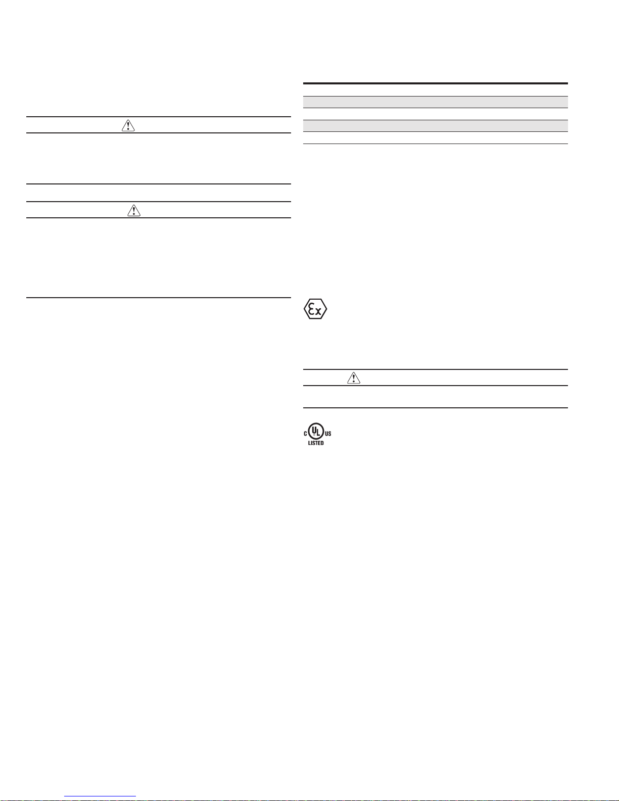
Module structure
The 215U-2 module is made up of different interface areas with a
central input and output storage area (I/O store). The I/O store is
an area of memory made available for the status of the physical
on-board I/O and internal I/O registers. It also provides services for
other processes within the module.
The I/O store is split into eight different block types:
•
Two blocks made available for bit data (discrete)
•
Two blocks made available for word data (analog)
•
Two blocks made available for 32-bit words data (32-bit analogs)
•
Two blocks made available for floating point data (floats)
Each of these block types in turn support input and output locations
that can interface with the physical I/O on the local machine and
also be used for data storage when used as a gateway to external
devices. These block type locations are illustrated in Figure 1 and
are described in “Register memory map” on page 45. There are
other registers within the database that can be used for system
management.
Figure 1. Module structure
The radio and Ethernet interfaces (see Figure 1) allow the 215U-2
to communicate with other modules within the system using a
proprietary protocol called WIB. I/O Messages from other 215U-2
modules are received on the communication ports and then passed
to the I/O store which will in turn update the register locations
accordingly. The WIB protocol is designed to provide reliable
communications suitable for an Ethernet channel or for an open
license-free radio channel. It is an extremely efficient protocol
for radio communications because the messages are sent using
exception reporting (only transmitting when there is a change of
an input signal) rather than transmitting all of the time. Update
messages can also be configured at a predetermined time for
integrity checks.
Each message can be comprised of multiple I/O values, referred
to as a “block of I/O.” The messages use error checking and return
acknowledgment for greater reliability. Up to four attempts are made
when transmitting the message over each hop of the radio path,
and if no acknowledgment is received a Comms indication can be
flagged.
The on-board I/O includes eight discrete I/O, two single-ended
analog inputs, two differential analog inputs, and two current
sourcing analog outputs. Each discrete I/O can function as either
a discrete input (voltage-free contact input) or discrete output
(transistor output). Each I/O point is linked to separate I/O registers
within the I/O data store.
The following internal I/O can be accessed from the I/O store. The
inputs can be used to interpret the status of a single module or an
entire system:
•
Battery voltage—The battery terminal voltage, displayed as an
analog value.
•
Loop supply—The +24 Vdc analog loop supply (ALS) used to
power analog current loops, displayed as an analog value.
•
Expansion module volts—The supply voltage of the connected
expansion modules, displayed as an analog value.
•
RSSI—The radio signal level received from the upstream device,
reported as a dB level.
•
Comms Fail—A selectable register can indicate a
Communications Fail error for a particular message transmission.
The expansion port, allows 115S expansion I/O modules to be added
to the module. Expansion I/O is dynamically added to the internal I/O
of the 215U-2 module by adding an offset to the address.
Getting started
Most applications for the 215U-2 module require little configuration.
The 215U-2 has many sophisticated features, but if you do not
require these features you can use this section to configure the
units quickly.
To get started quickly:
1. Read “Installation” on page 3, which describes the power
supply, antenna/coax connections, and I/O connections.
2. Power on the 215U-2 module and set up a USB connection to
your PC. For detailed steps, see “Connecting to the device” on
page 12.
2
EATON www.eaton.com
215U-2 802.11
wireless I/O and gateway
Installation
User Manual MN032EN
Effective October 2017
General
The 215U-2 Series modules are housed in a plastic enclosure with
DIN rail mounting, providing options for up to 14 I/O points, and
separate power and communications connectors. The enclosure
measures 7.2”x6.0”x1.3” (183mm x 156mm x 33mm), including
the connectors. The antenna protrudes from the top.
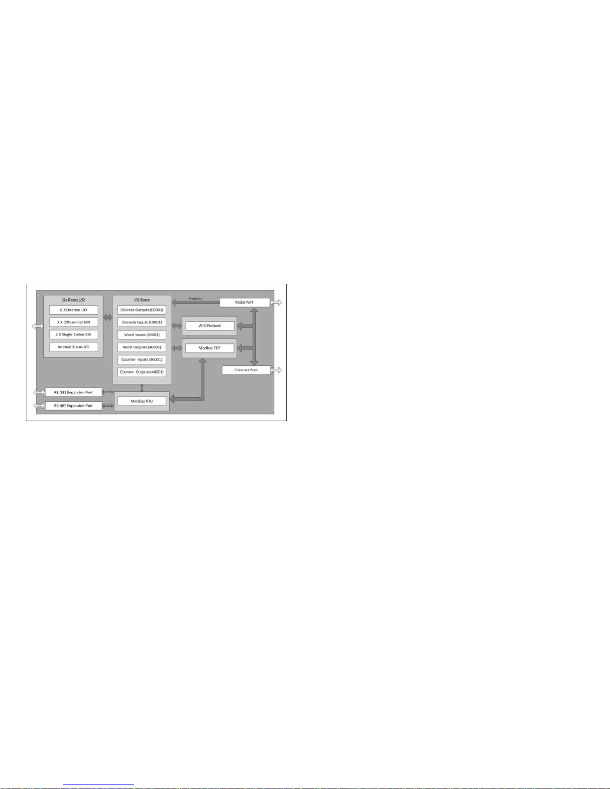
Power supply
SUP
BAT SUP
GND
+
B A
+
-
ETHERNET
USB RS232 SUPPLY
–
Optional
10.8–15 Vdc
Lead Acid
Battery
3A Fuse
+
+
-
15-30 Vdc
Supply
Figure 2. Supply connections
Powering from the SUP+ and SUP– terminals
The 215U-2 will operate from a 15–30 Vdc supply (nominal 24 Vdc)
connected to the SUP+ and SUP– terminals. The power supply must
be able to supply enough current to operate the device, to power all
of the I/O circuits, and to power the device’s radio transmitter when
it is sending data. A 24 Vdc 2.5 A power supply such as ELPRO
PSG60E or PS-DINAC-24DC-OK is suitable for all configurations,
including configurations requiring battery charging and expansion I/O.
If you need to use a supply with a lower power rating; or if you
need to power additional equipment in your installation; use these
guidelines to determine your required power supply current. Add
the relevant elements from Table 1 to determine your power supply
current requirement. Remember you also need to add current for
any other equipment being powered from the same power supply,
including relays, loop isolators, indicators, etc.
Table 1. Power supply current requirements
Supply voltage
17 Vd c 24 Vd c 30 Vdc
Base operating current 200 mA 150 m A 120 mA
Discrete I/O (per active input or output) 11 mA 7 mA 5 mA
Analog inputs and outputs
55 mA 38 mA 30 mA
(per 20 mA loop)
Connecting a back-up battery to the BAT+ and
GNDterminals
The 215U-2 provides an internal battery charger for Sealed Lead
Acid (SLA) batteries. You can connect a 13.8 V SLA battery to the
BAT+ and GND terminals to provide a backup power source if the
main supply fails. While the main supply is present, the battery will
charge at up to 0.5 A rate until the battery voltage reaches 14.3 V.
The battery charger will then maintain a float charge on the battery
at this voltage. To fully charge the SLA battery, the main supply must
be at least 17 Vdc.
When you connect a backup battery, you need to provide sufficient
power to support the additional charge current required when the
battery is discharged (when it is recovering from an extended power
interruption). Table 2 shows the additional current from your power
supply to support battery charging.
Table 2. Additional current to support battery charging
Supply voltage (V
) Current required (I
sup
)
sup
17 Vdc 1000 mA
24 Vdc 700 mA
30 Vdc 550 mA
Formula
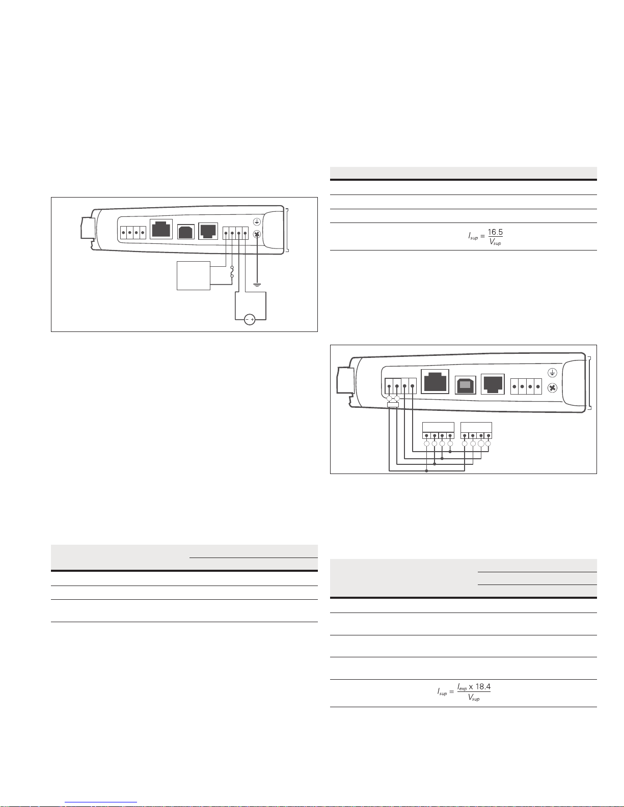
Powering expansion I/O modules
The 215U-2 allows connection of 115S Series modules to the RS-485
port to provide expanded I/O capacity. You can use the “+” and
“–“ connections on the 215U-2 to provide up to 500 mA supply for
expansion I/O modules. If you have a back-up SLA battery connected
to the 215U-2, then this connection will also be powered from the
back-up supply, so that the expansion I/O modules receive the
backup power as well as the main module.
SUP
BAT SUP
GND
+
B A
B A
RS-485
+
-
ETHERNET
B A B A
USB RS232 SUPPLY
115S-xx 115S-xx
+
-
+
-
+
-
Figure 3. Expansion I/O power and RS-485
When the module is being powered from the main supply (SUP+
and SUP– terminals), you need to provide sufficient power to
support the additional current required by the expansion I/O
modules. Table 3 shows the additional current from yourpower
supply to support expansion I/O connection.
Table 3. Additional supply current to support expansion I/O
Expansion
I/O
current
(I
)
exp
Current required (I
Supply voltage
17 Vd c 24 Vdc 30 Vdc
)
sup
Base operating current 115S 120 mA 130 mA 90 mA 75 mA
Discrete inputs
13 mA 14 mA 10 mA 8 mA
(per active input)
Discrete outputs
25 mA 27 mA 20 mA 16 mA
(per active output)
Analog inputs and outputs
50 mA 55 mA 38 mA 30 mA
(per 20 mA loop)
Formula
Powering the module directly from the BAT+ and
GNDterminals
In some situations it may be desirable to power the module
directly from a 13.8 Vdc supply. This may be because this voltage
supply is already available at an installation or because the power
EATON www.eaton.com
3
User Manual MN032EN
Effective October 2017
215U-2 802.11
wireless I/O and gateway
requirements for 115S modules are more than can be supplied by
the “+” and “–“ expansion I/O connections.
Use Table 4 to determine the device’s current requirements at
13.8 Vdc. Remember you also need to add current for any other
equipment being powered from the same power supply, including
relays, indicators, and any additional 115S modules.
Table 4. Current requirements
Supply current at 13.8 Vdc
Base operating current 230 mA
Discrete I/O (per active input or output) 10 mA
Analog inputs and outputs (per 20 mA loop) 50 mA
Internal I/O
The internal supply voltage register locations shown in the
following table can be monitored using the Diagnostics Web page
within the module’s Web-based configuration utility (see “Product
Reconfiguration” on page 36 for details). The values can also be
mapped to a register or an analog output on another module within
the network.
Table 5. Internal supply voltage registers
Register Description
30005 Local supply voltage (0–40 V scaling).
30006 Local 24 V loop voltage (0–40 V scaling). Internally generated
+24V supply used for analog loop supply. Maximum current
available is 100 mA.
30007 Local battery voltage (0– 40 V scaling).
30008 115S supply voltage (0–40 V scaling).
38005–38008 Floating point registers that display the actual supply voltage,
battery voltage, +24 V supply, and 115S supply. Note that these
are actual voltage values, whereas registers 30005 –30008
display a number between 8192 and 49152 that represents the
voltage scale 0–40 V.
To calculate the supply voltages from the register value use the
following calculation:
Volts = (Register Value) – 8192
1024
High and low voltage alarm indication may be configured for each of
these supply voltages. See "Analog inputs" on page 9 for details
on how to configure these alarms.
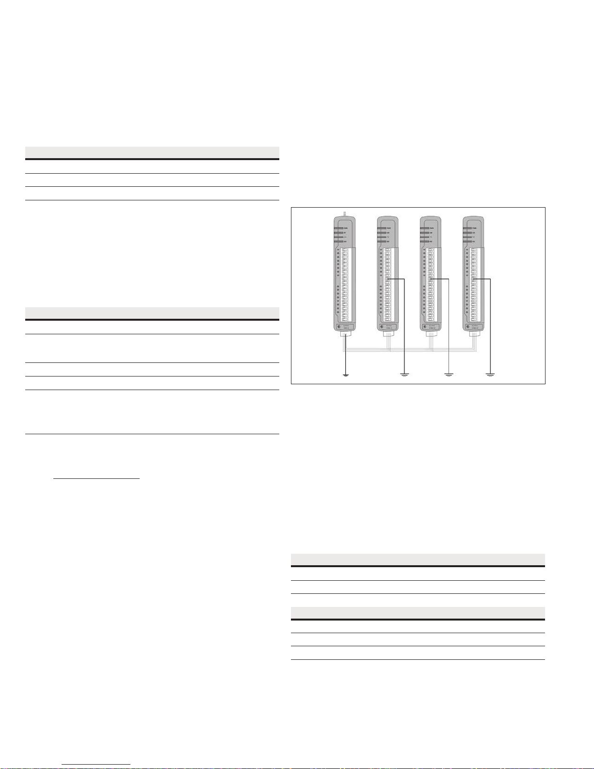
Grounding
To provide maximum surge and lightning protection each module
should be effectively earthed/grounded via a GND terminal on the
module. This is to ensure that the surge protection circuits inside the
module are effective. The module should be connected to the same
common ground point as the enclosure ground and the antenna
mast ground.
The 215U-2 has a dedicated earth/ground connection screw on the
bottom end plate next to the supply terminals. All earth/ground
wiring should be minimum 0.8in
2
(2 mm2), 14 AWG. If using the
215U-2 with serial expansion I/O modules, all expansion modules
must have a separate earth/ground connection from the front
terminal back to the common earth or ground point. See Figure 4.
Figure 4. Grounding
Antennas
Antennas can be either connected directly to the module’s
RFconnector or connected via 50-ohm coaxial cable (such as
RG58Cellfoil or RG213) terminated with a male SMA coaxial
connector. The higher the antenna is mounted, the greater the
transmission range, but as the length of coaxial cable increases
sodo cable losses.
The net gain of an antenna and cable configuration is the gain of the
antenna (in dBi) less the loss in the coaxial cable (in dB). Maximum
net gain for the 215U-2 will depend on the licensing regulation for
the country of operation and the operating frequency.
Typical antennas gains and losses are:
4
EATON www.eaton.com
Table 6. Typical antennas gains and losses
Antenna Gain (dBi)
Dipole 2 dBi
Collinear 5 or 8 dBi
Directional (Yagi) 6–15 dBi
Cable type Loss at 2.4GHz
RG58 cellfoil cable kits (3 m,10 m, 20 m) -1.8dB, -6dB, -12dB
RG213 per 10 m (33 ft) -4dB
LDF4 -50 per 10 m (33 ft) -2.2dB
The net gain of the antenna and cable configuration is determined
by adding the antenna gain and the cable loss. For example, an 8 dBi
antenna with 10 meters of Cellfoil (–6 dB) has a net gain of 2 dB
(8 dB – 6 dB).
215U-2 802.11
wireless I/O and gateway
User Manual MN032EN
Effective October 2017
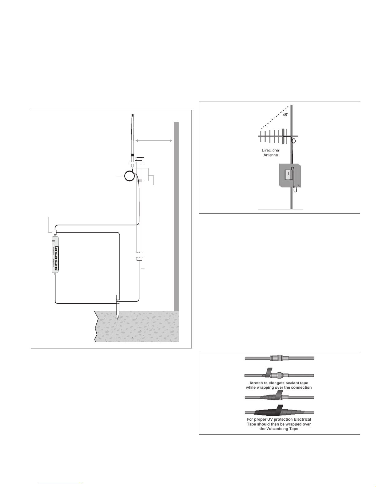
Dipole and Collinear antennas
Dipole and collinear antennas transmit the same amount of radio
power in all directions, and are easy to install and use because they
do not need to be aligned to the destination. The dipole antenna
does not require any additional coaxial cable. However, a cable must
be added if using any of the other collinear or directional antennas.
In order to obtain the maximum range, collinear and dipole antennas
should be mounted vertically, preferably at least one wavelength
away (see Figure 8 for distances) from a wall or mast and at least
3ft (1 m) from the radio module.
Stress
Relief
Loop
Antenna
*
1 Wavelength
(minimum)
Weatherproof
Connections
(recommended:
3M™ 23 selfbonding tape)
Wavelength:
2.4GHz: 5inch (12.5cm)
Surge Arrestor
(recommended)
Coaxial Cable
Directional radomes should be installed with the central beam
horizontal, and must be pointed exactly in the direction of
transmission to benefit from the gain of the antenna.
Parabolic antennas should be mounted according to the
manufacturer’s instructions, with the parabolic grid at the back and
the radiating element pointing in the direction of the transmission.
Ensure that the antenna mounting bracket is well connected
to ground.
Figure 6. Directional antenna
GND
215U-2
GND
at least 11 AWG (4 mm2)
Provide good ground
connection to mast,
module, and surge
arrestor.
If ground conditions
are poor, use more
than one stake.
Earth Stake
Mast
Earth Conductor
at least 5 AWG
(16 mm2)
For maximum
*
range, install
above local
obstructions.
Figure 5. Antennas installation—Collinear/Dipole
Directional antennas
A directional antenna provides high gain in the forward direction,
but lower gain in other directions. This type of antenna may be used
to compensate for coaxial cable loss for installations with marginal
radio path. Directional antennas can be any of the following:
•
Yagi antenna with a main beam and orthogonal elements
•
Directional radome, which is cylindrical in shape
•
Parabolic antenna
Yagi antennas should be installed with the main beam horizontal,
pointing in the forward direction. If the Yagi antenna is transmitting
to a vertically mounted omni-directional antenna, the Yagi elements
should be vertical. If the Yagi is transmitting to another Yagi, the
elements at each end of the wireless link need to be in the same
plane (horizontal or vertical).
Installation tips
Connections between the antenna and the coaxial cable should
be carefully taped to prevent ingress of moisture. Moisture
ingress in the coaxial cable is a common cause for problems with
radio systems because it greatly increases the radio losses. We
recommend that the connection be taped—first with a layer of PVC
tape, next with vulcanizing tape (such as 3M™ 23 tape), and finally
with another layer of PVC UV-stabilized insulating tape. The first layer
of tape allows the joint to be easily inspected when troubleshooting
because the vulcanizing seal can be easily removed (see Figure 10).
Where antennas are mounted on elevated masts, the masts should
be effectively grounded to avoid lightning surges. For high lightning
risk areas, approved ELPRO surge suppression devices, should be
fitted between the module and the antenna. The surge supression
must have a “turn on” voltage of between 10 and 20V. If the antenna
is not already shielded from lightning strike by an adjacent grounded
structure, a lightning rod may be installed above the antenna to
provide shielding.
Figure 7. Vulcanizing tape
EATON www.eaton.com
5
User Manual MN032EN
Effective October 2017
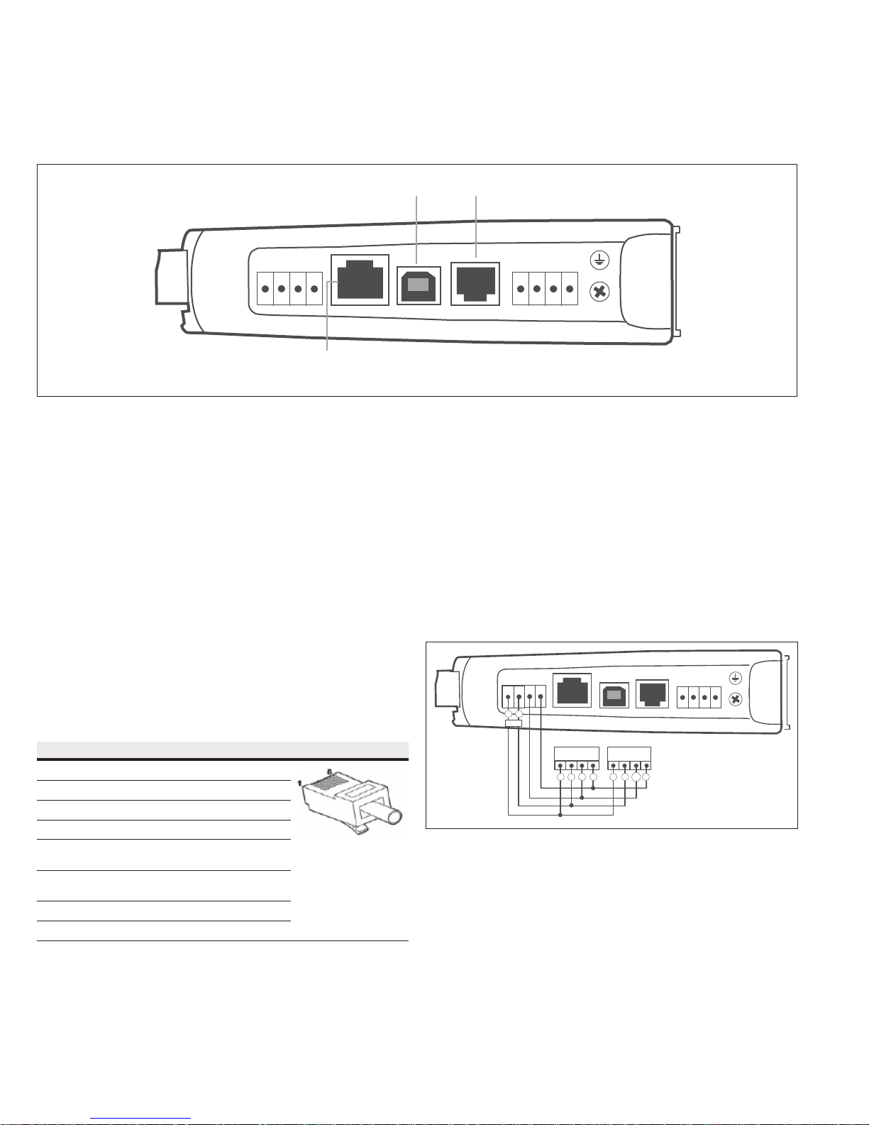
Connections
Bottom panel connections
Figure 8. Bottom panel connections
USB Port RS-232 Port
B A
+
-
ETHERNET USB RS232 SUPPLY
RJ-45 Ethernet Port
(connects to hub or switch)
GND
BAT SUP
+
215U-2 802.11
wireless I/O and gateway
SUP
+
-
Ethernet port
The 215U-2 modules provides a standard RJ-45 Ethernet port
compliant to IEEE 802.3 10/100Base-T. This port provides full
access to the module, including configuration, diagnostics, log file
download, and firmware upload of both the local and remote units.
Additionally, the Ethernet port can provide network connectivity for
locally connected third-party devices with Ethernet functionality.
USB device port for configuration
The 215U-2 module also provides a USB device (USB-B) connector.
This connector provides configuration of the device and remote
configuration access to other devices in the radio network.
RS-232 port
The 215U-2 module provides an RS-232 serial port that supports
operation at data rates up to 230,400 baud. This port supports
Modbus protocol. The RS-232 port is accessed using an RJ-45
connector wired as a DCE according to the EIA-562 Electrical
Standard.
Table 7. RJ-45 connector
RJ-45 Signal Required Signal name Connector
1 RI — Ring Indicator
2 DCD — Data Carrier Detect
3 DTR Y Data Terminal Ready
4 GND Y Signal Common
5 RXD Y Receive Data
(frommodule)
6 TXD Y Transmit Data
(tomodule)
7 CTS — Clear to Send
8 RTS — Request to Send
RS-485 port with Modbus support
The 215U-2 module provides an RS-485 serial port that supports
operations at data rates up to 230,400 baud. The default baud rate is
9600 baud, no parity, 8 data bits and 1 stop bit, which matches the
115S serial expansion module default settings. This port supports the
Modbus protocol.
The RS-485 port terminal is hosted on the four-way expansion
connector on the bottom edge of the module. An on-board RS-485
termination resistor provides line termination for long runs. As a
general rule, termination resistors should be enabled at each end
of the RS-485 cable. When using 115S expansion I/O modules,
remember to enable the RS-485 termination resistor switch that is
located on the end module.
SUP
BAT SUP
GND
+
B A
B A
RS-485
+
-
ETHERNET
B A B A
USB RS232 SUPPLY
115S-xx 115S-xx
+
-
+
-
+
-
Figure 9. RS-485 connections
6
EATON www.eaton.com
215U-2 802.11
wireless I/O and gateway
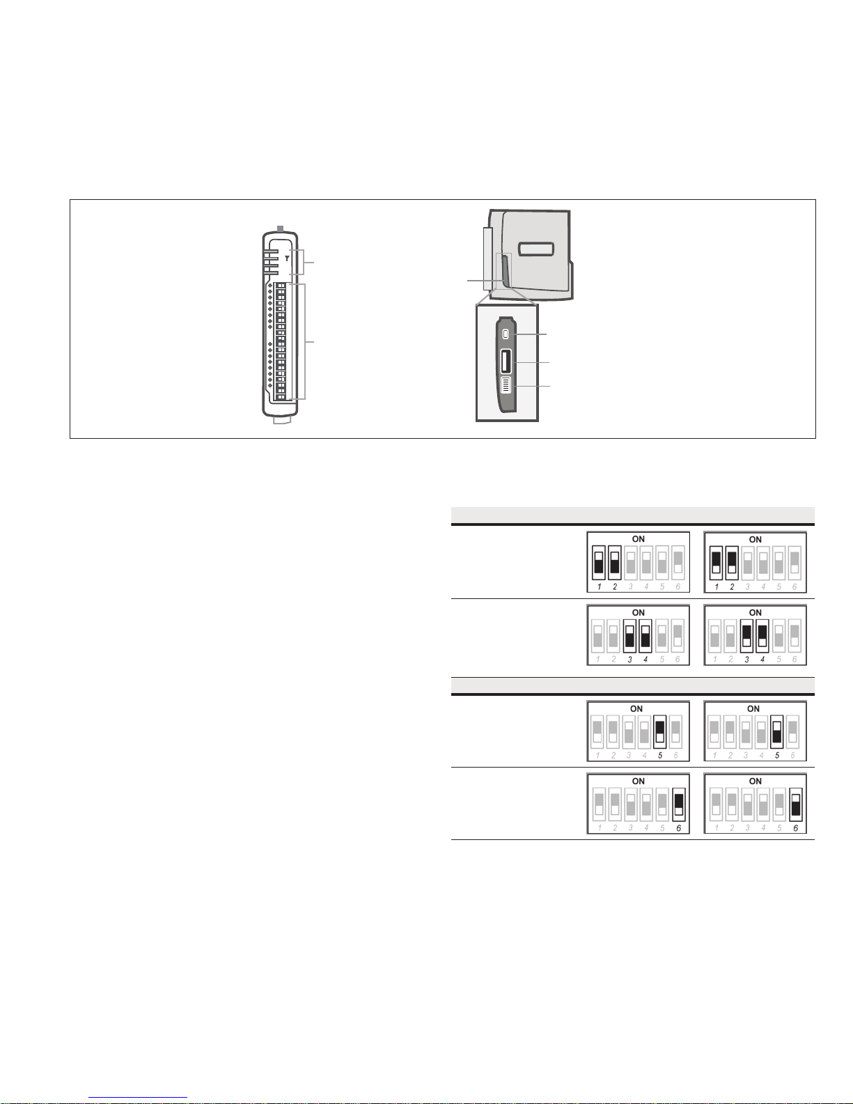
Side access configuration panel
A small access panel on the side of the module hides a factory boot
switch, USB host port, and a small bank of DIPswitches that are
used for analog input voltage and current selection, external boot,
and default configuration settings. Use a screw-driver to free the
latch to open the access panel.
PWR
RF
LED Indicator Lights
232
485
User Manual MN032EN
Effective October 2017
Side
Access
Panel
I/O Connectors
Figure 10. Access panel
Factory boot switch
The factory boot switch is used for factory setup and diagnostics.
This switch should only be used if advised by ELPRO technical
support.
USB host port
This port is a USB host (master port) that can interface with
USB storage devices for upgrading the module firmware and for
uploading logged data files. For details, see“To perform a full
firmware upgrade using USB flash drive” on page 53. Also see
“Data logging” on page 38.
DIP switches
The DIP switches are used to select a number of functions within
the module, as shown in the following table.
•
DIP switches 1 to 2—Used for measuring current or voltage
onanalog input 3. Set DIP switches to “on” to measure current
(0–20 mA) and “off” for voltage (0–5 Vdc).
•
DIP switches 3 to 4—Used for measuring current or voltage
onanalog input 4. Set DIP switches to “on” to measure current
(0–20 mA) and “off” for voltage (0–5 Vdc).
•
DIP switch 5—Not used.
•
DIP switch 6—When set to “on” (enabled) and the module is
restarted, the module boots up with a known factory default
configuration, including a default IP address for the Ethernet
connection. See “Connecting to the module” on page 13.
ote:N When DIP switch 6 is “on,” radio and I/O functionality isdisabled.
Factory Boot
Switch
USB Host
Conguration
Switches
Table 8. Switch functions
Switch Function Current Voltage
DIP 1 and 2 Analog
input 3
DIP 3 and 4 Analog
input 4
Switch Function Disabled Enabled
DIP 5 Not used
DIP 6 Setup mode
EATON www.eaton.com
7
User Manual MN032EN
Effective October 2017
215U-2 802.11
wireless I/O and gateway
Front panel connections
The front panel on the 215U-2 module provides connections for the
following:
•
Eight digital input/output (DIO 1–8)
•
Two 12-bit, 0.1% accuracy differential analog inputs
•
Two single-ended 12-bit, 0.1% accuracy analog inputs
•
Two 13-bit, 0.1% accuracy current sourcing analog outputs
•
Connection terminals for common and +24 V analog loop supply
(ALS); maximum ALS current limit is 100 mA
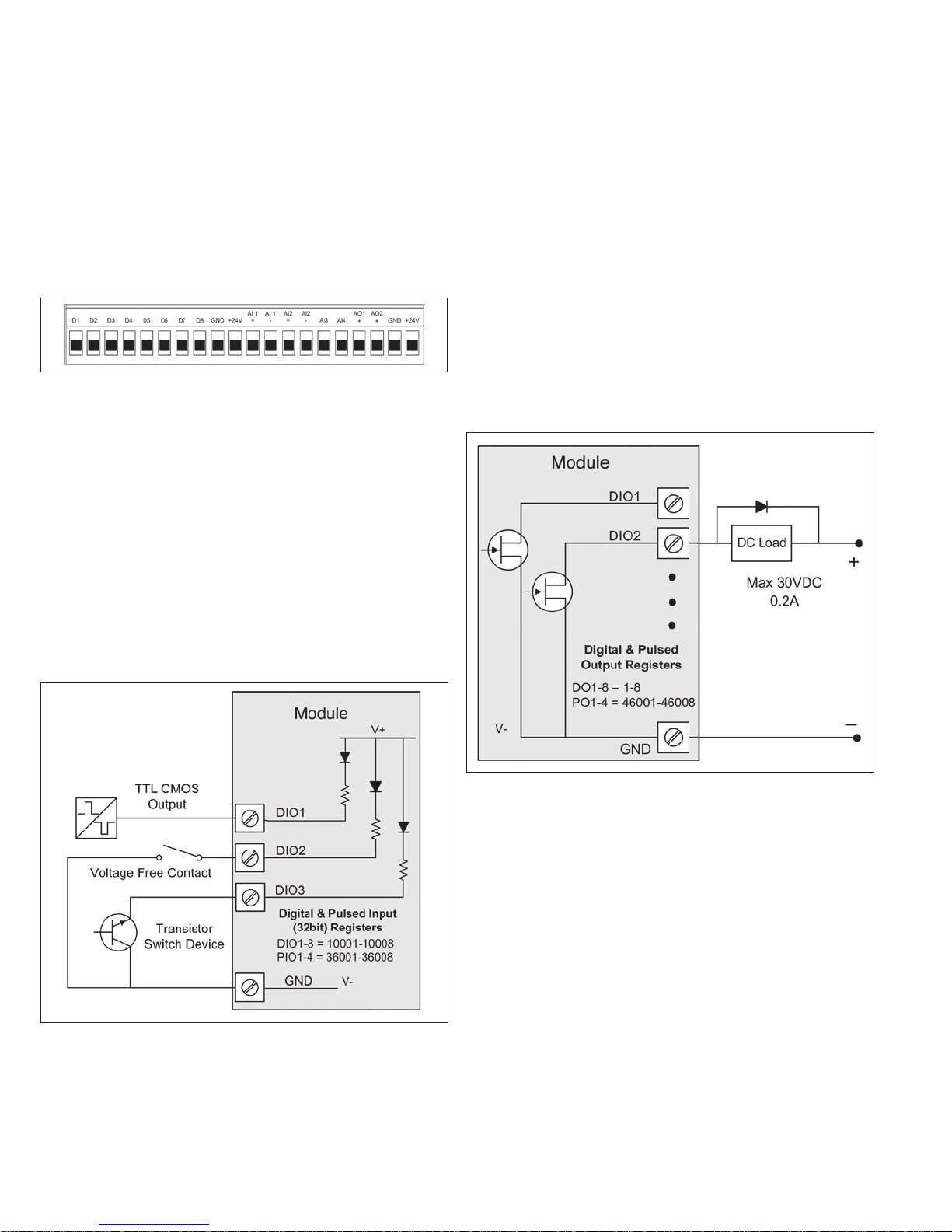
Figure 11. Front panel connections
Digital or pulsed inputs
Each digital I/O channel on the 215U-2 module can act as either
an input or an output. The input/output direction is automatically
determined by the connections and configuration of the I/O. If you
have an I/O channel wired as an input but operate the channel as an
output, no electrical damage will occur but the I/O system will not
operate correctly. If you are operating the channel as an output and
you read the corresponding input value, it will indicate the status of
the output.
Marked D1–8, the digital inputs share the same terminals as the
digital outputs on the 215U-2 module. A digital input is activated by
connecting the input terminal to GND or common, either by voltagefree contact, TTL level, or transistor switch. Each digital input has
an orange indication LED that will turn on when the input has been
connected to a GND.
Digital inputs 1–4 can be used as pulsed inputs. The maximum pulse
frequency is 50 kHz for input 1 and 2, and 1kHz for input 3 and 4.
Digital/pulsed inputs are suitable for TTL signal level, NPN-transistor
switch devices, or voltage-free contacts (a relay or switch with
debounce capacitor).
Frequencies greater than 1 kHz need to use a TTL logic drive or an
external pull-up resistor (1 KΩ to V+). Pulsed inputs are converted
to two different values internally. The first value is the pulse count,
which is an indication of how many times the input has changed
state over a configured time period. The second value is a pulse
rate, which is an analog input derived from the pulse frequency.
Forexample, 0 Hz = 4 mA and 1 kHz = 20 mA.
All pulsed input counts are stored in non-volatile memory, so thatthe
values are saved in the event of a power failure or a modulereset.
Digital outputs (pulsed outputs)
Digital outputs are open-collector transistors, and are able to switch
loads up to 30 Vdc, 200 mA. The eight digital outputs sharethe
same terminals as the digital input. These terminals aremarked D1–8.
Figure 12. Digital/pulsed input wiring
8
EATON www.eaton.com
Figure 13. Digital pulsed output wiring
When active, the digital outputs provide a transistor switch to
EARTH (Common). To connect a digital output, see Figure 13. A
bypass diode (IN4004) is recommended to protect against switching
surges for inductive loads such as relay coils. The digital channels
D1–4 on the 215U-2 module can be used as pulse outputs with a
maximum output frequency of 10 kHz.
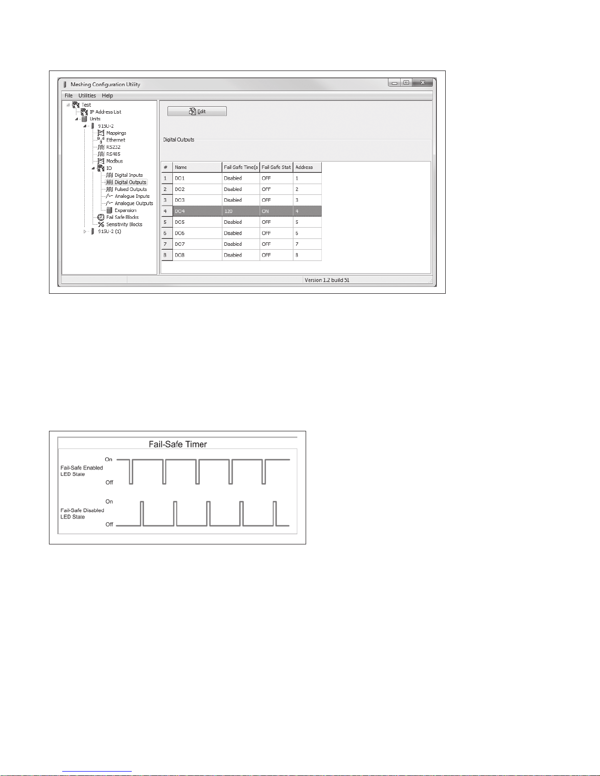
Digital output fail-safe status
In addition to indicating the digital output status (on or off), the LEDs
can also indicate a communications failure by flashing the output
LED. This feature can be used by configuring a fail-safe time and
status via the I/O Digital Output screen in the MConfig utility.
215U-2 802.11
wireless I/O and gateway
Figure 14. Digital output fail-safe times
User Manual MN032EN
Effective October 2017
The fail-safe time is the time the output counts down before
activating a fail-safe state. Normally this would be configured for a
little more than twice the update time of the mapping that is sending
data to it. This is because the fail-safe timer is restarted whenever
it receives an update. If you send two successive updates and fail
to receive both of these messages, the timer counts down to zero
and activates the fail-safe state. If the fail-safe state is enabled (on),
the LED flashes briefly off and the digital output turns on. If the failsafe state is disabled (off), the LED flashes briefly on and the digital
output turns off.
Figure 15. Fail-safe state
Analog inputs
The 215U-2 module provides two floating differential analog inputs
and two grounded single-ended analog inputs. Analog inputs 1 and
2 will automatically measure current (0–20 mA) or voltage (0–25V),
depending on what is connected to the input. Analog inputs 3 and 4
must be configured to measure current (0–20 mA) or voltage (0–5V)
via the DIP switches on the configuration panel (see “Side access
configuration panel” on page 7).
An internal 24 V analog loop supply (ALS) provides power for any
current loops with a maximum current limit of 100mA. The LEDs
have an analog diagnostic function and will indicate the status of the
input. The LED comes ON when any analog signal is detected, and
will go OFF when the analog signal drops to zero.
ote:N By default, there is a one-second delay on the input because of the
filter. Filter times can be changed using the Analog Input screen within the
MConfig utility. For more information, see "Analog inputs" on page 9.
The LEDs next to AI1+, AI2+ indicate the current on these inputs.
The LEDs next to AI1– and AI2– indicate the voltage on the
analog inputs.
EATON www.eaton.com
9
User Manual MN032EN
Effective October 2017
215U-2 802.11
wireless I/O and gateway
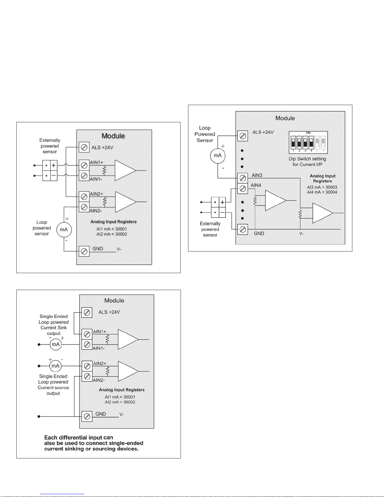
Differential current inputs
Only analog input 1 and 2 can be wired as differential Inputs.
Differential mode current inputs should be used when measuring a
current loop, which cannot be connected to ground. This allows the
input to be connected anywhere in the current loop. Common mode
voltage can be up to 27 Vdc.
Figure 16 indicates how to connect loop-powered or externally
powered devices to the 215U-2 differential analog inputs. It should
also be noted that the differential inputs can also be used to connect
single-ended current sinking or current sourcing devices. Figure 18
shows how to connect to these types of devices.
Single-ended current input mode is useful if the sensor loop is
grounded to the 215U-2 module. Devices can be powered from the
24V analog loop supply (ALS) generated internally from the module.
The DIP switches (located in the side access panel) are used to
determine if the inputs will be current or voltage. DIP switches 1
and 2 are used for analog 3, and DIP switches 3 and 4 are used for
analog 4. For current, set both DIP switches to the “on” position.
Forvoltage, set both to “off.”
Figure 16. Differential current inputs (AI1 and AI2)
Figure 18. Al3 and Al4 Single-ended current inputs
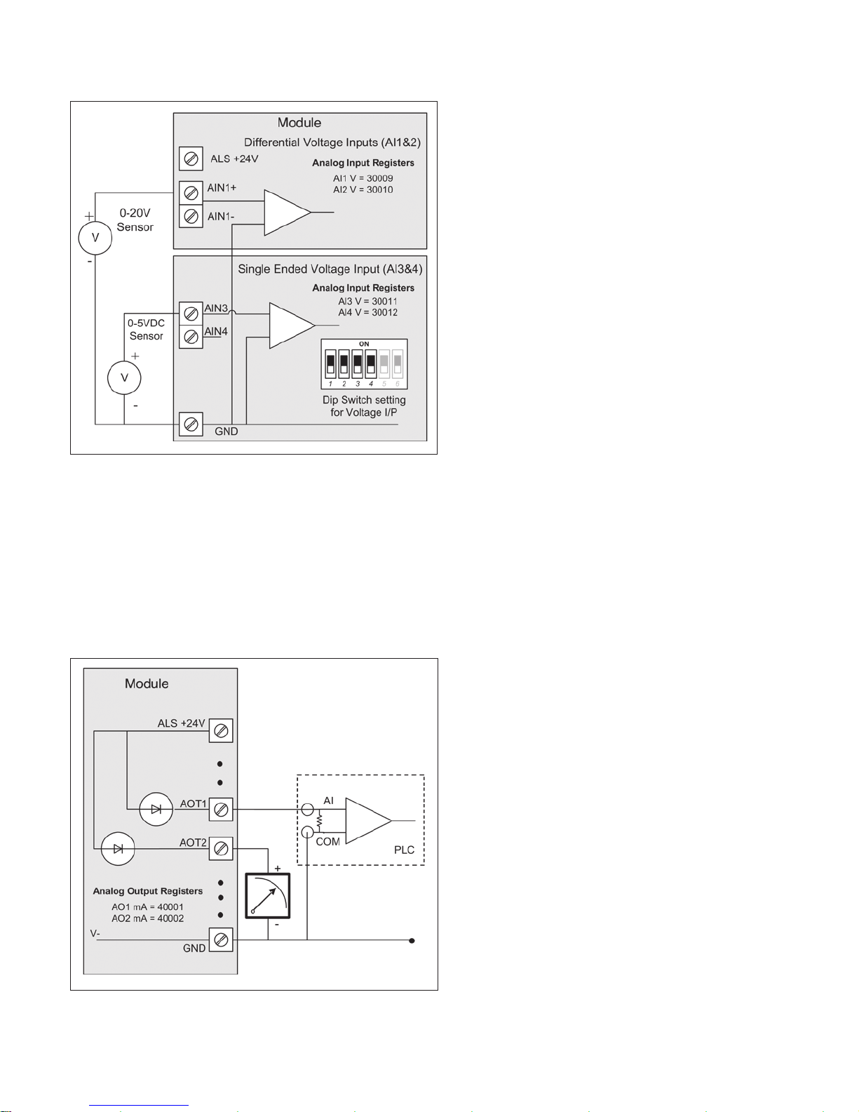
Voltage inputs
All analog inputs can be set up to read voltage. If using analog input
1 and 2, connect the voltage source across the positive terminal of
the input and ground. If using analog input 3 and 4, connect across
the input terminal and GND.
ote:N Default scaling gives 0–20 V for 0–20 mA output on analog 1 and 2.
Default scaling for analog 3and4 gives 0–5 V for 0–20mA output. For voltage
input on analog 3 and 4, set both DIP switches to the OFF position.
Figure 17. Al1 and Al2 single-ended current inputs
10
EATON www.eaton.com
215U-2 802.11
wireless I/O and gateway
Figure 19. Single-ended voltage inputs
Analog outputs
The 215U-2 module provides two 0–24 mA DC analog outputs for
connecting to analog inputs on equipment (such as PLCs, DCS, and
loggers) or connecting to instrument indicators for displaying remote
analog measurements. The 215U-2 analog outputs are a sourcing
output and should be connected from the analog output terminal
through the device or indicator to ground (GND). See Figure 20 for
connections. The LEDs provide level indication depending on current.
The LEDs appear dimmed for 4 mA and bright for 20 mA.
User Manual MN032EN
Effective October 2017
System design
Design for failures
All well-designed systems consider system failure. I/O systems
operating on a wire link will fail eventually. Failures can be shortterm, such as interference on the radio channel or power supply
failure, or long-term, such as equipment failure.
The modules provide the following features for system failure:
•
Outputs can reset if they do not receive a message within a
configured time. If an output should receive an update or change
message every 10 minutes and it has not received a message
within this time, some form of failure is likely. If the output
is controlling machinery, it is good design to switch off the
equipment until communications are re-established.
•
The modules provide a fail-safe feature for outputs. This is a
configurable time value for each output. If a message has not
been received for this output within the configured time, the
output will assume a configured value. We suggest that this reset
time be a little more than twice the update time of the input. It
is possible to miss one update message because of short-term
interference. However, if two successive update messages are
missed, long term failure is likely and the output should be reset.
For example, if the input update time is three minutes, set the
output reset time to seven minutes.
•
A module can provide an output that activates on communication
failure to another module. This can be used to provide an external
alarm indicating that there is a system fault.
Testing and commissioning
We recommend that the system is fully bench tested before
installation. It is much easier to find configuration problems on
the bench when the modules are next to each other as opposed
to being miles apart. When the system is configured and you are
confident that it works, back up the configurations of all modules.
Figure 20. Analog outputs
EATON www.eaton.com
11
User Manual MN032EN
Effective October 2017
Connecting to the device
To configure the 215U-2 you connect to it using a web browser on
your PC or mobile device.
Connecting to the module for the first time
On first connection, you can only connect to the device through
its USB port. Once you have connected to the device for the first
time, you can enable access through the Ethernet port and remotely
through the 802.11 Wireless port.
ote:N Before enabling the Ethernet Port or Wireless port for Configuration
access, read the section “Device Security”.
Connecting to the device’s USB port
The USB port is located on the bottom side of the module. (Refer
Figure 11 “Bottom Panel Connections”). To connect, you need an
USB cable (USB-A to USB-B) for connecting from your computer to
the module’s USB-B port.
If this is the first time you have used your computer to connect
to an ELPRO device through the USB port, then you will need to
download the USB driver file from the product’s internet website.
This is available from the same location that you downloaded this
user manual.
You will also need to know the username/password configured for
the device. If the module is new out-of-the-box you can use the
default settings. Otherwise, you may need to restore these settings.
If you have lost the password, you can set the username and
password back to the default values. For instructions, see “Restoring
the factory default connection settings” on page 42.
1. Install the USB Device driver to your PC. You do this by running
the installer ".exe" file and following the prompts.
2. Power on the device, and wait for the device to finish booting
and for the “PWR” LED to go solid green (about 1 minute).
3. Plug in the USB cable and wait for your computer to recognize
the new USB device.
4. Once the device is connected, you will have an additional
Network Adapter in your device manager list
“Elpro 215U-2 USB Ethernet/ RNDIS Interface”
5. Open your web browser (recommended Internet Explorer
version 10 or later) and type “http://192.168.111.1” into the
browser bar. The device’s USB address is always the same.
The module responds with a username and password box.
6. Type the username and password. The default username is
“user” and the default password is “user”.
215U-2 802.11
wireless I/O and gateway
The module’s default settings are as follows:
IP Address 192.168.0.1XX
(shown on the printed label on the side of
the module)
Subnet Mask 255.255.255.0
User Name user
Password user
ote:N You cannot access the device through Ethernet until remote access
has been enabled. The first time you access the device, you need to use the
USB method described above. Then you can enable remote access on the
quick start configuration page.
Once you have the device’s IP address and password:
1. Connect an Ethernet cable between the module’s Ethernet port
and the PC.
2. Configure your PC networking settings to be on the same
network as the device. For instructions on how to do this, see
“Configuring PC networking settings for Ethernet and Wireless”
on page 42.
3. Open your web browser (recommended Internet Explorer
version 10 or later) and type “http://” followed by the IP address
of the module and press Enter.
The module responds with a username and password box.
If the module does not respond, check that you have configured
your PC according to the section “Configuring PC networking
settings for Ethernet and Wireless” on page 42.
4. Type the username and password. The default username is
“user” and the default password is “user”.
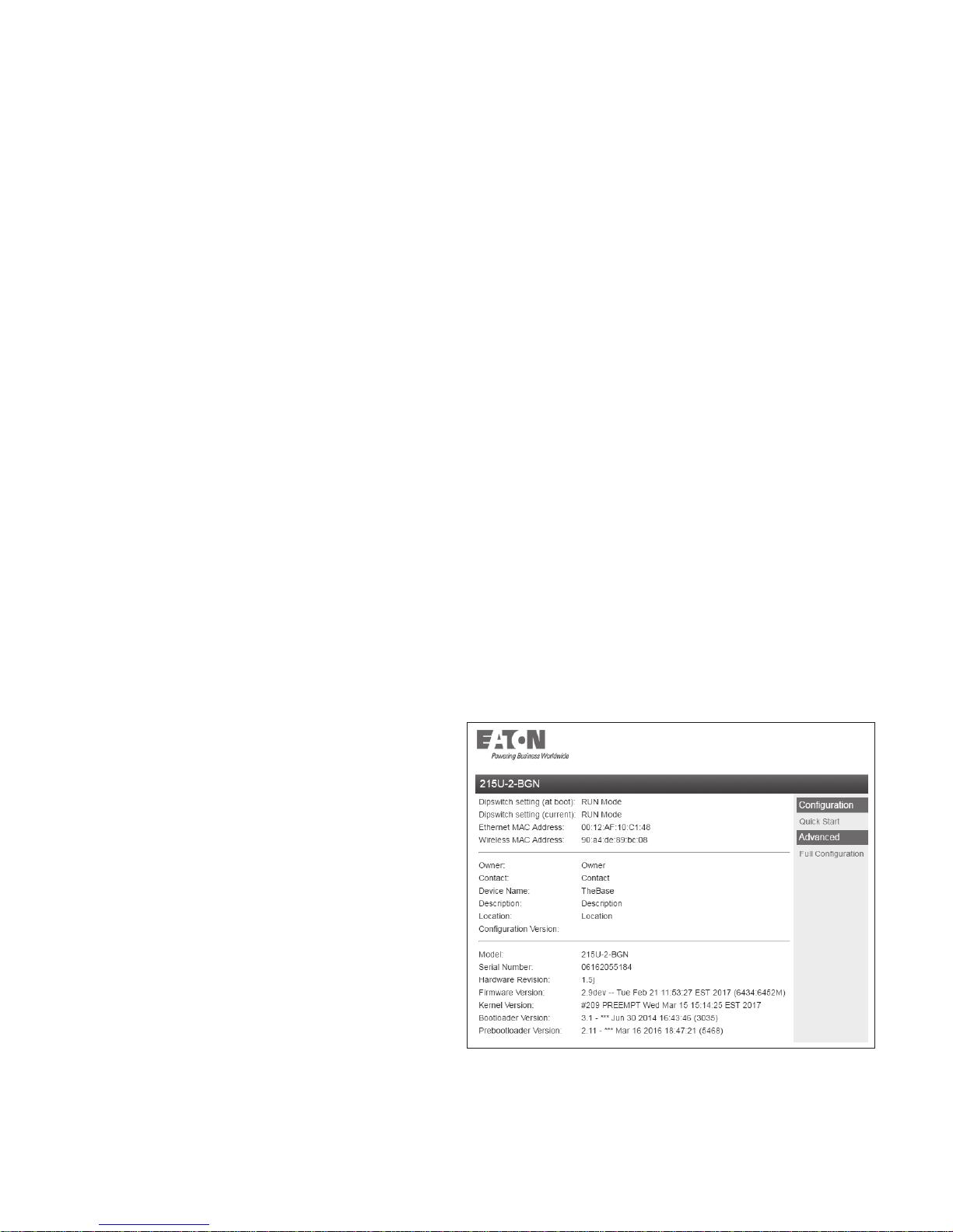
This connects you to the home page of the Web-based configuration
utility (see Figure 21). This utility allows you to manage wireless
connection links between all modules in the system through a
standard browser, such as Microsoft
®
Internet Explorer®.
This connects you to the home page of the Web-based configuration
utility (see Figure 21). This utility allows you to manage wireless
connection links between all modules in the system through a
standard browser, such as Microsoft
®
Internet Explorer®.
Connecting to the Device’s Ethernet port
The Ethernet port is located on the bottom side of the module.
(Refer Figure 8 “Bottom Panel Connections”). To connect, you need
an Ethernet cable for connecting to the module’s Ethernet port.
You also need to know the device’s IP Address and the username/
password configured for the device.
12
EATON www.eaton.com
Figure 21. Device home page
215U-2 802.11
wireless I/O and gateway
User Manual MN032EN
Effective October 2017
Device Security
The 215U-2 supports industrial protocols such as Modbus and WIB
that do not provide encryption or authentication. These protocols are
convenient to use as they are widely known and supported by an
extensive range of equipment.
The downside of using these protocols is that they are also
vulnerable to a variety of cyber-attacks, so you must consider the
security of the networks that they operate over.
As a precaution, these protocols are disabled in the default
configuration. Before enabling any of these protocols, you should
ensure that the following precautions are in place.
•
Change the device’s access password from the default (“user”).
•
Make sure that any network connected to the device’s Ethernet
port is secured from outside access. If an internet connection is
present, ensure it is effectively firewalled.
•
Secure the radio network using WPA-PSK encryption.
•
Ensure that the radio network encryption passphrase is long (at
least 20 characters) and complex. Quality of security assurance
offered depends on the complexity of this passphrase. Short
and simple passphrases can easily be compromised by skilled
attackers.
•
Ensure that knowledge of the radio network encryption
passphrase is kept to a limited number of workers and ensure the
access password and radio passphrase are changed whenever
any of these workers' security status changes.
•
Ensure physical security of the devices connected to the network.
•
In the event that a device is lost or stolen, ensure that the
encryption key used to secure communications on the radio
network is changed.
Peer-to-Peer I/O mapping, Serial port configuration, Data Logging,
Advanced networking configuration, diagnostics, and User
management. These pages are described later in this manual.
•
If your system is based on Modbus TCP protocol, you need to
enable Modbus TCP Server by selecting Full Configuration >>
Modbus TCP and checking "Enable Modbus TCP Server". Once
you have the device configured, you will be able to access it using
a Modbus TCP client (Master) at the IP address you configure.
ote:N Before navigating away from this page, you need to click the “Save
Changes” or “Save Changes and Reset” button at the bottom of the page.
Otherwise your changes will be lost.
Security
Enable Remote Configuration Access: Select this to enable access
to the device configuration and the dashboard web pages through
Ethernet or Wireless interfaces. If this is not selected, you can only
access the device web pages through the USB connection.
Identification
System Name: All devices in a system are configured with a
common system name. This is used in ProMesh mode as a common
network ID for all devices to connect.
Device Name: Each device in the system should be configured
with a unique device name. This name is used to identify devices in
diagnostic display (Connectivity) and is used in Fixed Link mode as
the device ID for other devices to connect to.
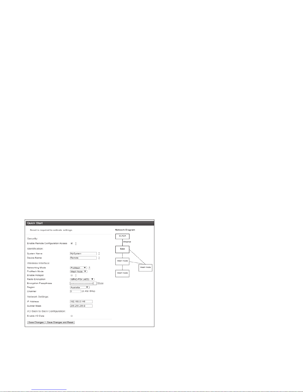
Quick start conguration
Access the quick start configuration by clicking on the “Quick Start”
text on the right side menu under “Configuration”.
Figure 22. Quick start
•
For the majority of installations, you will only need to access
this Quick Start page. This configuration will get your devices
connected and communicating. You can then connect remotely if
you need to configure other functionality.
•
Click “Full Configuration” to access advanced configuration pages.
These pages provide access to additional functionality including
EATON www.eaton.com
13

User Manual MN032EN
Effective October 2017
215U-2 802.11
wireless I/O and gateway
Wireless Interface
Networking Mode: You can choose one of three networking modes
depending on your system requirements:
•
Manual Mode implements traditional 802.11 networking
configuration. You configure units as Access Point or Client. Client
units connect to an Access Point with matching SSID (System
Address).
•
ProMesh Mode implements automatic repeater configuration,
where devices (Mesh Node) automatically choose and maintain
the best path back to a central station (Base). All devices in the
network use a common SSID (System Name).
•
Fixed Links Mode implements a fixed repeater configuration
where field devices (Remote) are configured to connect directly or
via intermediate sites (Repeater) to a central station (Base).
802.11 Mode: This option is available when the Networking mode
is set to Manual. A traditional 802.11 network has a single Access
Point and one or more Clients.
•
System Address (ESSID): This is the “Extended Service Set
Identification” used in 802.11 mode. For a client to connect, the
client needs to have this set to the same value configured on the
Access Point.
ProMesh Mode: This option is available when the Networking Mode
is set to ProMesh. A ProMesh network consists of a single central
station (Base), and one or more remote sites (Mesh Nodes) which
can each operate as a repeater for other stations.
The Mesh Nodes select the best path to the Base depending on
the number of hops to the base, and based on signal strength of
the hops in the path. Once connected, the Mesh Nodes monitor
the path quality and will swap to use a better path if one comes
available.
All devices in a ProMesh network share the same SSID (the
configured “System Name”).
•
Enable Hotspot: This option is only available for Mesh Nodes
in a ProMesh network. Because the ProMesh is designed to
be flexible, the Mesh Nodes devices may not always advertise
for a connection. If you want to be able to connect from a non
ProMesh device to one of the Mesh Nodes, then select this
option on that Mesh Node to ensure it remains available for
connection.
Device Mode: This option is available when the Networking mode
is set to “Fixed Links”. A Fixed Link network consists of a central
station (Base) accessing a fixed arrangement of repeater stations
(Repeater) and remote stations (Remote). All devices ultimately
connect to the central station (Base). Repeaters and remotes can
either connect directly to the base, or connect using additional
repeater stations to extend the radio range.
•
Upstream Device Name: When the Device Mode is “Repeater”
or “Remote”, you need to select the Upstream device. When
the connection is direct to the base, this is the Device Name
of the base station. When the connection is via repeaters, this
is the name of the repeater station that is used to reach the
base station.
Radio Encryption: Select the desired Encryption mode. Normally
this should be WPA2-PSK (AES), which is the strongest encryption
available. Only select other modes if you need to do this to connect
to a third party or legacy system that does not support WPA2
protocol.
ote:N Selecting Encryption “None” or “WEP” makes your network vulnerable
to attack. This product makes use of standard 802.11 physical signaling, so
without encryption there is no protection from attackers with off-the-shelf
hardware. Selecting WEP provides very limited protection from attack. WEP
protocol has known weaknesses that make it relatively simple to penetrate.
Encryption Passphrase: This is the secret key for your network
encryption. All devices in the network need the same passphrase to
communicate.
ote:N For best security, this passphrase must be long (at least 20 characters)
and should not include text that could be guessed such as names, dates, etc.
ote:N Always keep this passphrase private, and ensure that the system
configuration is updated with a new passphrase if this key becomes
compromised.
Region: The module is configured from the factory to allow
operation globally. To take advantage of additional radio channels
and higher allowed power in some countries, you can select a
different region. The power is automatically set to the maximum
for the selected region. Refer to the table below for the maximum
radiated power in different regions. You can adjust the power on the
Radio page (“Full Configuration >> Radio” on right side menu) to
accommodate higher gain antennas if needed. Note that every time
you change the Region selection, the power setting reverts to the
maximum for that region.
Table 9.
Region Allowed channels Power setting Maximum EIRP
North America 1-11 23 dBm (200mW) +36 dBm
Europe 1-13 20 dBm (100mW) +20 dBm
Australia 1-13 23 dBm(200mW) +36 dBm
Channel: You can select a radio channel to avoid interference from
other 802.11 networks in your area, or to allocate radio spectrum
between several of your own networks. For 802.11 communication,
channels 1,6, and 11 are non-overlapping.
Network settings
IP Address: This selects the IP address for the device. You can leave
this at the default value, which is printed on the module side label.
If you chose to do this, take care that you don’t have two modules
with the same IP address assigned (The default IP address is
assigned from the factory based on the last two digits of the device
serial number).
Subnet Mask: The subnet mask identifies how the IP address is
divided between the local device address and the global network
address. The default subnet mask of 255.255.255.0 allocates 24
bits to the network address, and 8 bits for the host device. This
allows up to 254 devices (hosts) on a single network. If you need to
support more devices, or if you need to operate within an existing
addressing scheme, you should discuss this setting with an IP
network expert.
14
EATON www.eaton.com

215U-2 802.11
wireless I/O and gateway
User Manual MN032EN
Effective October 2017
Additional network settings items
These additional items will display on the Quickstart page
if the Network Mode has been modified in the Advanced
Networking configuration. Normally they will not be visible
on the Quickstart page.
Network Mode: This allows you to choose between bridged and
routed networking. Bridged networking is the simplest to configure
and will be the correct choice in almost all networks.
•
Bridge: The 215U-2 acts as a network bridge between the radio
and Ethernet ports. Ethernet packets are transparently passed
between the radio and Ethernet ports using rules learned from
traffic that has already passed.
•
Router: The 215U-2 acts as an IP Router between the radio and
Ethernet ports. Only IP packets are passed between the radio
and Ethernet, which are on separate sub-networks. You configure
the rules for which packets are transferred on the routing
configuration page.
Wireless IP Address/Netmask: When the network mode is set to
Router, the Ethernet and Wireless interfaces on the device each
have separate IP addresses. This sets the IP address for the
wireless interface.
I/O Back to Back configuration
This provides a simple method to configure I/O mappings between
two sites in a system. When the networking mode is ProMesh, you
can select this check box to configure the device to automatically
send the I/O data to another device connected to the same network.
You can also connect 115S-12 and 115S-13 modules to provide
additional I/O points.
When you select this option, input data from a remote site is sent to
the system Base. Input data at the base is sent to the remote site
that first sends the data to the Base. You should only set this option
at the base and at one remote site in the system. For more detail
on how this feature operates, refer to section "Default Back-To-Back
gather scatter mapping" on page 20.
Save Changes: Clicking this button saves changes to non-volatile
storage. Changes don’t take effect until the device has been
restarted. If you plan to make changes to multiple pages, use this
button before navigating to another page.
Save Change and Reset: Clicking this button immediately applies
the changes on you have made by saving the new configuration to
non-volatile storage, then forcing the device to reset immediately.
Once the device has booted, the new changes will be in effect.
Connecting to Other 802.11 devices
The 215U-2 uses standard 802.11 networking protocols and it is
possible to use it in conjunction with other 802.11 devices, either
joining an existing network, or allowing other devices to join the
215U-2 network.
mode and passphrase to match the settings in the existing network.
You also need to find the correct network name (SSID) to connect
to. This depends on the type of network you have configured as
shown below:
•
Manual: To connect to an “Access Point” unit in “Manual” mode,
connect to the network which matches the unit’s configured
“System Address (ESSID)” parameter.
ote:N You cannot connect to a “Station (Client)” unit.
•
Fixed Links: To connect to a “Base” unit or a “Repeater” unit in
“Fixed Links” mode, connect to the network that matches the
unit’s configured “Device Name”. Each Base and Repeater should
have a unique device name in the network.
ote:N You cannot connect to a “Field Station” unit.
•
ProMesh: Connecting to device configured for “ProMesh” mode
takes some care. In a ProMesh network all the devices share the
same SSID. This is the configured “System Name”, so your device
may see multiple networks with the same name.
You will always be able to connect to the “Base” unit by selecting
the correct network. For “Mesh Node” units, you must check
the “Enable Hotspot” check box on the unit’s configuration page
to ensure that it remains available for connection. Normally you
can connect to the unit with the best signal strength, and use
the 215U-2 ProMesh network to automatically reach the unit you
need to access.
Your device might also need to be configured with the correct IP
Address. You can do this through manually configuring your device,
or using automatic IP address assignment (DHCP). If you need
your device to be assigned an IP Address through DHCP, you can
configure the DHCP server on the central unit in the 215U-2 network
(This is the Base unit or the Access Point unit). You can access the
DHCP Configuration by selecting “Full Configuration >> DHCP
Server” on the right side menu. Refer to section “DHCP Server” on
page 27 for information on configuring the DHCP server.
Accessing Ethernet devices connected to 215U-2
You can connect devices such as PLCs or HMIs to the Ethernet port
on the remote 215U-2 devices. With the default configuration, you
will be able to access these devices directly from a PC or HMI at the
central site.
The 215U-2 default configuration bridges the wireless and Ethernet
connections. This means that all of the devices, including devices
connected to the remote Ethernet ports, are connected to a single
bridged network.
The 215U-2 can also be configured to route between the Wireless
and Ethernet ports. If you configure your 215U-2 network as a
routed network, then you will need to set up routing rules in your
devices to allow the data packets to reach the correct destination.
Connecting a 215U-2 to existing 802.11 network
To connect to an existing 802.11 Access Point, you need to set
encryption mode and passphrase to match the existing network.
•
For a Manual Mode Client – Set the “System Address (ESSID)”
field to match the SSID of the Access Point
•
For a ProMesh Mesh Node, set the “System Name” field to
match the SSID of the Access Point.
•
For a Fixed Mesh Repeater and Fixed Mesh Remote, set the
“Upstream Device” field to match the SSID of the Access Point.
Connecting your device to an existing 215U-2 network
To connect an 802.11 capable device as a client to an existing
network of 215U-2 devices, you need to set the device’s encryption
EATON www.eaton.com
15
 Loading...