

ELPRO 115S Series Quick Setup Manual
© ELPRO Technologies. June 2007. V1.5
inst_115S_1.5.doc
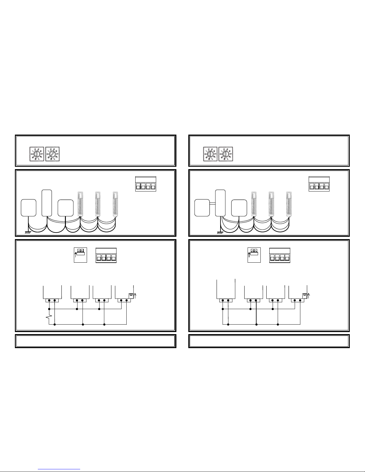
115S-Series Quick setup guide
Modbus
master
115S 115S 115S
Set a unique Modbus slave address for each 115S
connected to the Modbus master.
Example here address = 01.
Master
power
supply
Connect power:
(10.8-15.6 VDC) to ‘+’
and EARTH to ‘-‘.
115S-11: 300mA max
115S-12: 600mA max
115S-13: 650mA max
B A - +
POWER
ADDRESSING
x10 x1
ON
B A - +
A, B: Connect RS485
(Modbus)
RS485
termination
switch.
Up = terminate
Down = unterminated
Power and
Modbus
connector
RS485
Modbus
master
115S 115S 115S
ABABABA
B
Termination
switch up
(terminated)
120
Ω
ø
2mm EARTH wire
115S
power
supply
12VDC
power
power
power
power
modbus
modbus
modbus
earth
Connection to a Modbus master
Consult user manual for Modbus addresses.
E-series
radio
115S 115S 115S
Address switches must be 00 for E-Series protocol.
Master
power
supply
Connect power:
(10.8-15.6 VDC) to ‘+’
and EARTH to ‘-‘.
115S-11: 300mA max
115S-12: 600mA max
115S-13: 650mA max
B A - +
POWER
ADDRESSING
x10 x1
ON
B A - +
A, B: Connect RS485
(Modbus)
RS485
termination
switch.
Up = terminate
Down = unterminated
Power and
Modbus
connector
RS485
E-Series
radio
(RS485-
terminated)
115S 115S 115S
ABABABA
B
Termination
switch up
(terminated)
ø
2mm EARTH wire
Battery
12VDC
power
power
power
modbus
modbus
modbus
earth
Connection to E-Series Radio
Set up using ELPRO E-Series configuration utility.
power
sup
bat
© ELPRO Technologies. June 2007. V1.5
inst_115S_1.5.doc
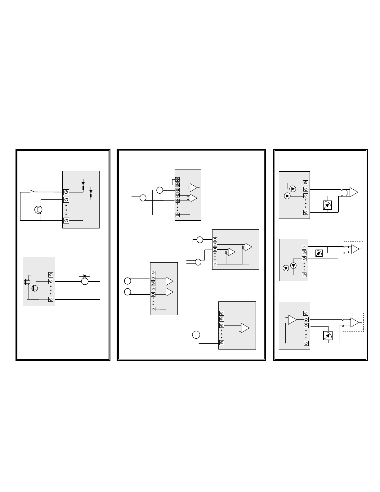
115S-Series Quick setup guide - Wiring
Voltage-free contact
Transistor
switch
device
V+
V+
V-
DIO1
DIO2
EARTH
115S Module
_
DC
Load
Max 30VDC
0.25A
DIO1
DIO2
EARTH
115S Module
V-
AIN3
AIN4
AGND
115S-12
ALS +24V
Externally
powered
sensor
-
AIN1
AIN2
Loop powered
sensor
Power
supply
V-
AIN1
AIN2
AGND
ALS +24V
Loop powered
sensor
Externally
powered
sensor
-
V-
AIN3
AIN4
AGND
115S-12
ALS +24V
Sensors with
voltage signals
AIN1
AIN2
-
AIN1
AIN2
AGND
115S-12
ALS +24V
Sensor with
voltage signal
115S-11
115S-12
DIGITAL INPUTS
DIGITAL OUTPUTS
DIFFERENTIAL
CURRENT INPUTS
(Select using config software)
SINGLE-ENDED
CURRENT INPUTS
(Default configuration)
DIFFERENTIAL
VOLTAGE INPUTS
(Select using config software)
SINGLE-ENDED
VOLTAGE INPUTS
(Select using config software)
115S-13
AOT1
AOT2
AGND
115S-13
ALS +24V
PLC
COM
CURRENT
SOURCE OUTPUT
(Default configuration)
V-
AOT1
AOT2
AGND
115S-13
ALS +24V
PLC
AI+
AI-
+
CURRENT SINK
OUTPUT
(Select using config software)
V-
AOT1
AOT2
AGND
115S-13
ALS +24V
PLC
VOLTAGE
INPUT
AI
COM
VOLTAGE OUTPUT
(Select using config software)
 Loading...