

Page 1
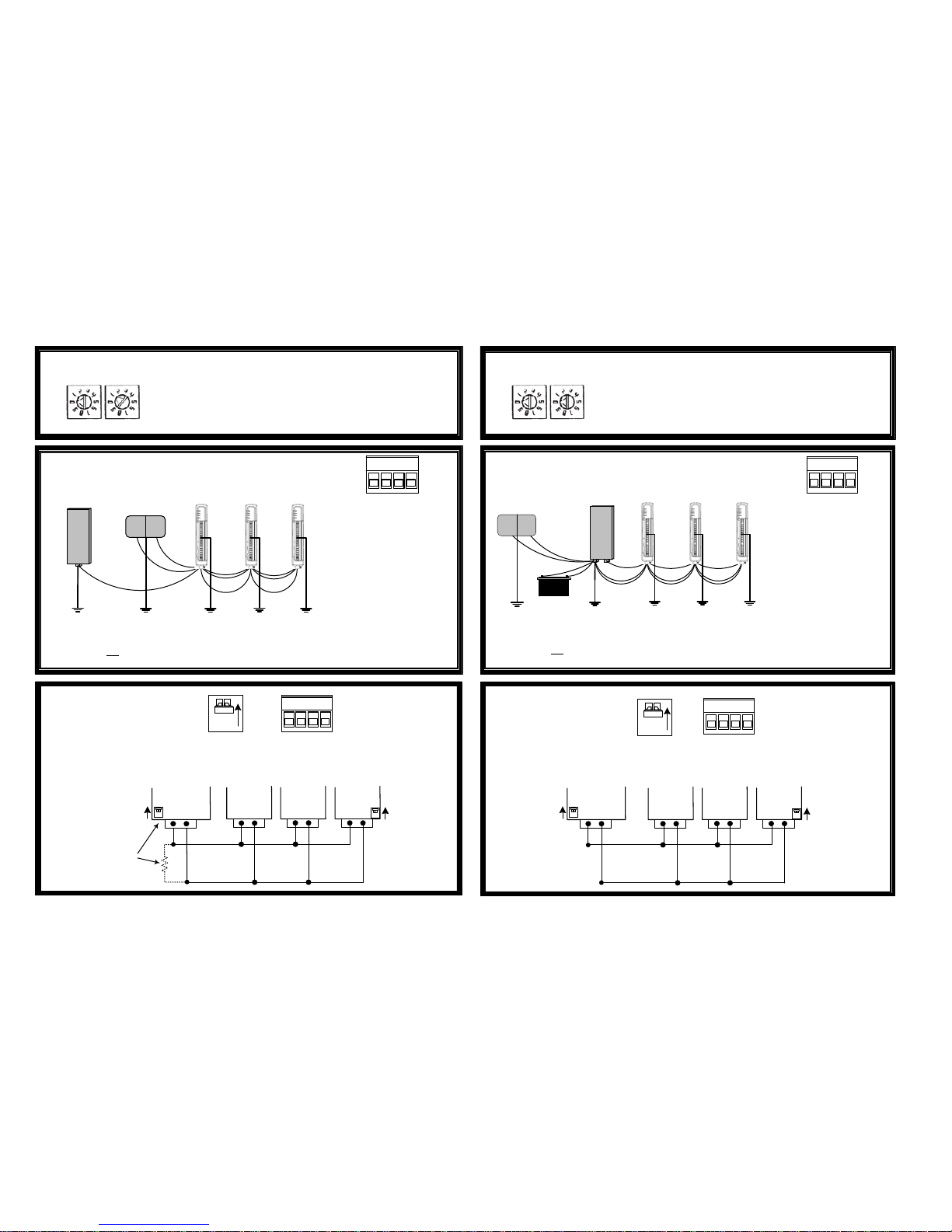
A, B: Connect RS485
(Modbus)
RS485
termination
switch
Up = terminated
Down = un-terminated
Power and
Modbus
connector
Modbus
Master
115S 115S 115S
A
AB ABAB
RS485
RS485
Termination
switch up
(terminated)
Set a unique Modbus slave address for each 115S
connected to the Modbus Master
Example shows address “01”
Consult user manual for Modbus addresses
ADDRESSING
x10
x1
115S
B A
-
+
POWER
Modbus
Master
Power
Supply
Power Connections:
EARTH wiring minimum 2mm² - 14 AWG
B A
-
+
ON
115S Quick Setup Guide - Connections
inst_115S_1.13.vsd © ELPRO Technologies.
Address switches must be 00 for E-Series protocol
Example shows address “00”
Setup using ELPRO E-Series configuration utility.
ADDRESSING
x10
x1
Connection to Modbus Master
Connection to E-Series Radio
Power
Power
Power
Modbus
Modbus Modbus
+
-
A, B: Connect RS485
(Elpro)
RS485
Termination
switch
Up = terminated
Down = un-terminated
Power and
RS485
connector
E-Series
Module
115S 115S 115S
AB
AB AB AB
RS485
RS485
Termination
switch up
(terminated)
B A
-
+
POWER
E-Series
Radio
Power
Supply
Power Connections:
115S-11: 300mA max
115S-12: 900mA max
115S-13: 900mA max
+
-
B A
-
+
RS485
Termination
switch up
(terminated)
ON
**Check rear label for
operating voltages
Power Power Power
RS485
RS485
RS485
Battery
_
+
Supply
Earth
115S 115S
B
RS485 Termination
switch up (terminated)
or
120Ω Fitted across
RS485
115S 115S 115S
Earth
EarthEarth
Earth
Earth
Earth
Earth Earth
Earth
‘+’ : Pos Supply
(10.8 to 30 VDC**)
‘-’ : Neg Supply
Ensure all earth connections are at the same potential.
EARTH wiring minimum 2mm² - 14 AWG
Ensure all earth connections are at the same potential.
THIS EQUIPMENT IS SUITABLE FOR USE IN CLASS 1 DIVISION 2 GROUPS A,B,C AND D, OR NONHAZARDOUS LOCATIONS ONLY.
WARNING ‐ EXPLOSION HAZARD ‐ DO NOT DISCONNECT EQUIPMENT WHILE THE CIRCUIT IS LIVE OR UNLESS THE AREA IS KNOW TO BE FREE OF IGNITABLE CONCENTRATIONS.
WARNING ‐ EXPLOSION HAZARD ‐ SUBSTITUTION OF ANY COMPONENT MAY IMPAIR SUITABILITY FOR CLASS I, DIVISION 2.
115S-11: 300mA max
115S-12: 900mA max
115S-13: 900mA max
**Check rear label for
operating voltages
‘+’ : Pos Supply
(10.8 to 30 VDC**)
‘-’ : Neg Supply
Page 2
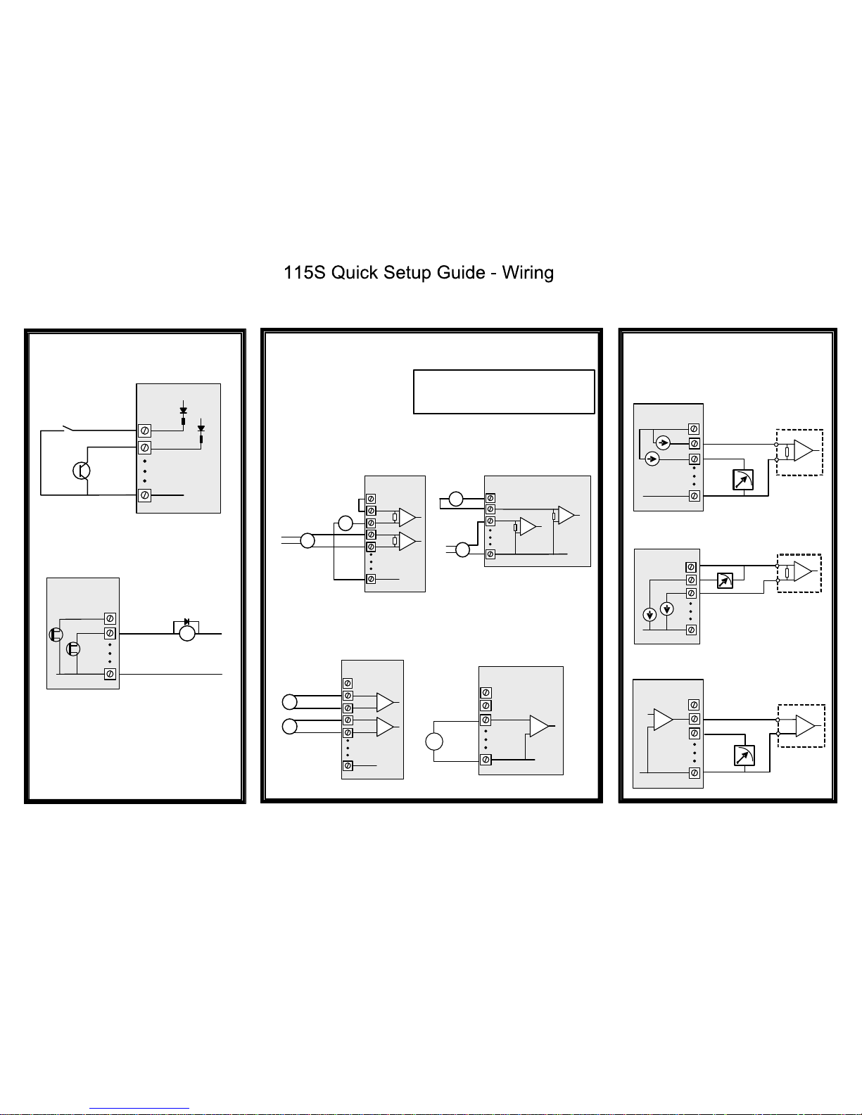
inst_115S_1.13.vsd
© ELPRO Technologies
Voltage free
contact
Transistor
switch
device
V+
V+
DIO1
DIO2
115S Module
_
+
DC
Load
Max 30VDC
200mA
V-
DIO1
DIO2
GND
115S Module
115S-11
DIGITAL
INPUTS
V-
AIN3
AIN4
GND
ALS +24V
AIN1
AIN2
Power
Supply
V-
AIN1
AIN2
GND
ALS +24V
Loop powered
sensor
V-
AIN3
AIN4
GND
ALS +24V
Sensors with
voltage
signals
AIN1
AIN2
V-
AIN1
AIN2
GND
115S-12
ALS +24V
Sensor with
voltage signal
DIFFERENTIAL
CURRENT INPUTS
(Default configuration)
(Select using DIP switches AND
config software)
V-
AOT1
AOT2
GND
ALS +24V
PLC
AI
COM
+
-
CURRENT SOURCE OUTPUT
(Default configuration)
V-
AOT1
AOT2
GND
ALS +24V
PLC
AI+
AI-
+
-
CURRENT SINK OUTPUT
(Select using config software)
V-
AOT1
AOT2
GND
115S-13
ALS +24V
PLC VOLTAGE
INPUT
AI
COM
+
-
VOLTAGE OUTPUT
(Select using config software)
WARNING !
115S-12
115S-13
DIGITAL
OUTPUTS
DIFFERENTIAL
VOLTAGE INPUTS
SINGLE ENDED
VOLTAGE INPUTS
SINGLE ENDED
CURRENT INPUTS
(Select using DIP switches AND
config software)
115S-12
115S-12
Externally
powered sensor
(Select using DIP switches AND
config software)
Loop powered
sensor
115S-12
Externally
powered sensor
V-
GND
+
-
-
+
-
+
+
-
+
-
+
+
-
115S-13
Ensure correct DIP switch positions AND
software configuration has been completed for
each analogue input BEFORE connecting
external signals to the 115S-12 module.
THIS EQUIPMENT IS SUITABLE FOR USE IN CLASS 1 DIVISION 2 GROUPS A,B,C AND D, OR NONHAZARDOUS LOCATIONS ONLY.
WARNING ‐ EXPLOSION HAZARD ‐ DO NOT DISCONNECT EQUIPMENT WHILE THE CIRCUIT IS LIVE OR UNLESS THE AREA IS KNOW TO BE FREE OF IGNITABLE CONCENTRATIONS.
WARNING ‐ EXPLOSION HAZARD ‐ SUBSTITUTION OF ANY COMPONENT MAY IMPAIR SUITABILITY FOR CLASS I, DIVISION 2.
 Loading...