

Page 1

Installation
Manual
105U-L Wireless
I/O
Version 1.8
man_105U-L_installation_v1.8 .doc
Page 2

105U-L Wireless I/O Installation Manual
105U-L Wireless I/O Page 2 of 38
Version 1.8
Document information
Installation Manual 105U-L Wireless I/O Version 1.8
ELPRO contact details
Address > 9 /12 Billabong Street Stafford, QLD 4053
Telephone > + 61 (0)7 3352 8600
Fax > + 61 (0)7 3352 8677
Email >
Website >
www.elprotech.com
Copyright
Copyright © 2007 ELPRO Technologies Pty Ltd. All rights reserved.
Limited lifetime warranty, disclaimer and limitation of remedies
ELPRO products are warranted to be free from manufacturing defects for the “serviceable lifetime” of the product.
The “serviceable lifetime” is limited to the av ailability of electronic components. If the serviceable life is reached in
less than three years following the original purchase from ELPRO, ELPRO will replace the product with an equivalent
product if an equivalent product is available.
This warranty does not ex tend to:
- Failures caused by the operation of the equipment outside the particular product's specification, or
- Use of the module not in accordance with this User Manual, or
- Abuse, misuse, neglect or damage by external causes, or
- Repairs, alterations, or modifications undertaken other than by an authorized Service Agent.
ELPRO’s liability under this warranty is limited to the replacement or repair of the product.
This warranty is in lieu of and exclusive of all other warranties. This warranty does not indemnify the purchaser of
products for any consequential claim for damages or loss of operations or profits and ELPRO is not liable for any
consequential damages or loss of operations or profits resulting from the use of these products. ELPRO is not liable
for damages, losses, costs, injury or harm incurred as a consequence of any representations, warranties or
conditions made by ELPRO or its representatives or by any other party, except as expressed solely in this document.
Page 3

105U-L Wireless I/O Installation Manual
105U-L Wireless I/O Page 3 of 38
Version 1.8
Contents
Contents __________________________________________________________________ 3
Safety information ................................................................................................................................ 4
Hazardous Location Notice s : ............................................................................................................... 4
About this document ............................................................................................................................ 4
Installing your unit __________________________________________________________ 5
Unit components and connections....................................................................................................... 6
Transmitter unit ............................................................................................................................................... 6
Receiver unit ................................................................................................................................................... 9
Installing the antenna ......................................................................................................................... 11
Supported antennas ...................................................................................................................................... 11
Radio transmission distances ........................................................................................................................ 13
Installing and earthing antennas ................................................................................................................... 14
Dipole and collinear antennas ....................................................................................................................... 15
Dipole antennas ........................................................................................................................................ 15
Collinear antennas .................................................................................................................................... 15
Yagi antennas ............................................................................................................................................... 17
Installing the power supply ................................................................................................................ 19
Inputs and outputs _________________________________________________________ 20
Digital inputs .................................................................................................................................................. 21
Relay outputs ................................................................................................................................................ 22
Status outputs ............................................................................................................................................... 23
Analog input .................................................................................................................................................. 24
Thermocouple input....................................................................................................................................... 27
Pulse input .................................................................................................................................................... 28
Analog output ................................................................................................................................................ 29
Installing and configuring the unit ____________________________________________ 31
Installing the unit ................................................................................................................................ 32
Configuring your units ........................................................................................................................ 33
Testing your units .............................................................................................................................. 34
Unit specifications _________________________________________________________ 35
Transmitter unit .................................................................................................................................. 35
Receiver unit ...................................................................................................................................... 35
Ancillary hardware reference information .......................................................................................... 36
RS232 serial cable ........................................................................................................................................ 36
Index ____________________________________________________________________ 37
Page 4
105U-L Wireless I/O Installation Manual
105U-L Wireless I/O Page 4 of 38
Version 1.8
Safety information
Thank you for selecting the 105U-L for your telemetry needs. We trust it will give you many years of valuable service.
To ensure your 105U-L enjoys a long life, double-check ALL your connections with the Installation Guide before
powering on the module.
WARNING: Incorrect termination of supply wires may cause internal damage and will void warranty.
Hazardous Location Notices:
This device complies with
Ex nL IIC. T6 -40 C <= Ta <= +60 C
WARNING: EXPLOSION HAZARD.
Do not disconnect equipment unless power has been switched off or the area is known
to be non-hazardous
About this document
This document is the 105U-L Wireless I/O Installation Manual that describes how to
install your 105U-L units and contains important information for installing your units with
other equipment.
Note
If your network only contains one transmitter and receiver pair, you should also read
the 105U-L QuickStart Guides.
This document contains the following sections:
Section Read this section if you want to …
Basic steps for using your unit
Learn the basic steps for installing and using your unit.
Factory default configuration
Understand how the transmitter sends information to the receiver.
Unit components
Understand the different parts of your unit.
Antenna installation
Learn how to install an antenna with your unit.
Resetting factory defaults
Reset your unit to the original factory default settings.
Linking transmitter and receiver units
Link your units to work as a dedicated pair.
Safety information
Understand important safety information related to your unit.
NOTE: You must read this information before installing your unit.
Specifications
Know technical information about your unit.
For more information, see the next sections.
In order to comply with Electrical Safety Regulations, this module must be installed in an Electrical AND
Fire enclosure. This enclosure may be a single or multiple enclosures. Access to the module is to be
made by a Service Person only.
**IMPORTANT ELECTRICAL SAFETY INFORMATION**
Page 5
105U-L Wireless I/O Installation Manual
105U-L Wireless I/O Page 5 of 38
Version 1.8
Installing your unit
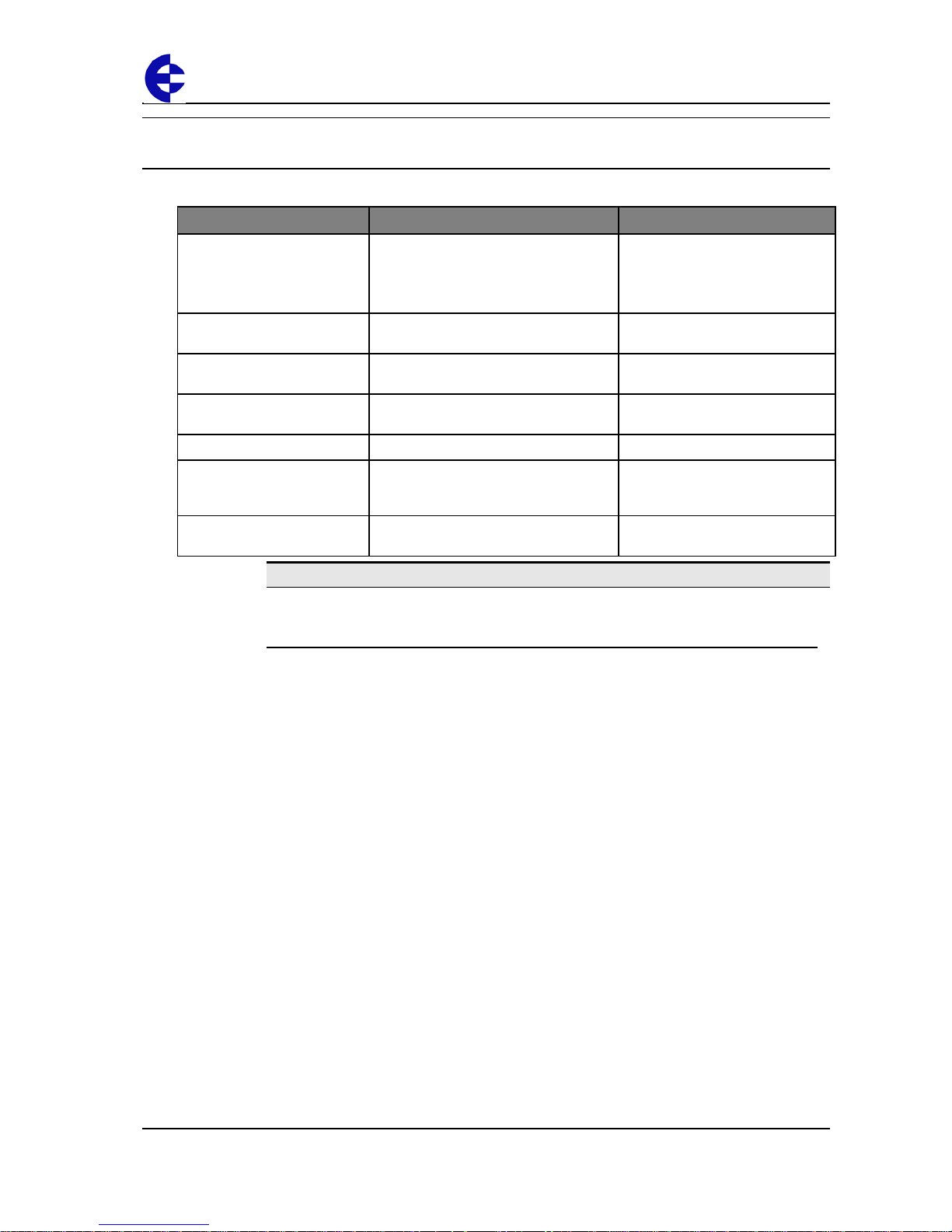
This section describes how to install your unit and contains the following sections:
Step Description For more information, see …
1 – Read the safety
information
Lets you understand important safety
information related to your unit.
NOTE: You must read this information
before installing your unit.
Safety Information on page 5.
2 – Get to know the unit
features
Understand the basic features of your
unit.
Unit components and connections
on page 6.
3 – Install the antenna
Learn how to install an antenna with
your unit.
Installing the antenna on page 11.
4 – Install the power supply
Learn how to install a power supply for
your unit.
Installing the power supply on
page 19.
5 – Install the units
Learn how to install your unit. Installing the unit on page 32.
6 – Linking and configuring
the unit
Learn how to link and configure your
units to transmit and receive
information.
Configuring your units on page 33.
7 – Test the unit
Understand the principles for testing
your units.
Testing your units on page 34.
Note
To ensure internal surge protection works correctly, you must earth each unit using
the Earth terminal.
For more information, see the next sections.
Page 6
105U-L Wireless I/O Installation Manual
105U-L Wireless I/O Page 6 of 38
Version 1.8
Unit components and connections
This section shows the components and terminal connections for the transmitter and
receiver units.
Transmitter unit
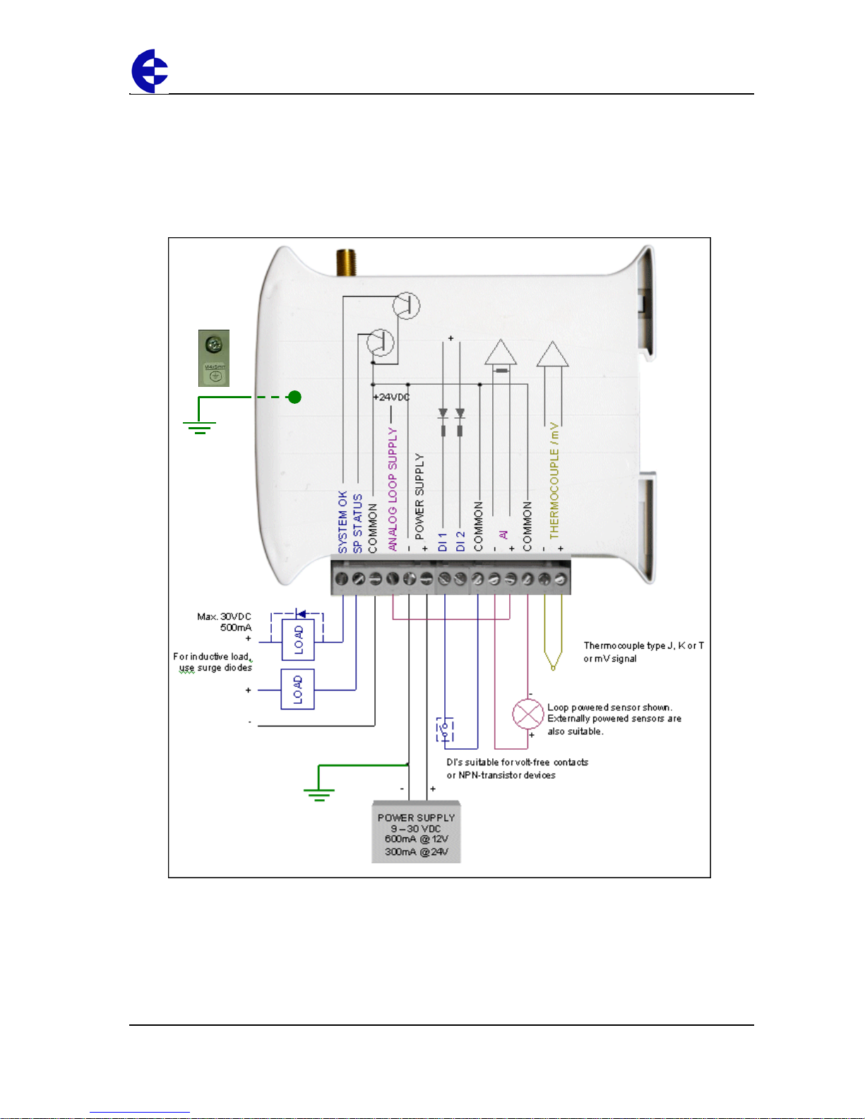
The 105U-L-T transmitter unit has the following components and terminal connections:
Earth Wire Lug
underneath Unit
Page 7
105U-L Wireless I/O Installation Manual
105U-L Wireless I/O Page 7 of 38
Version 1.8
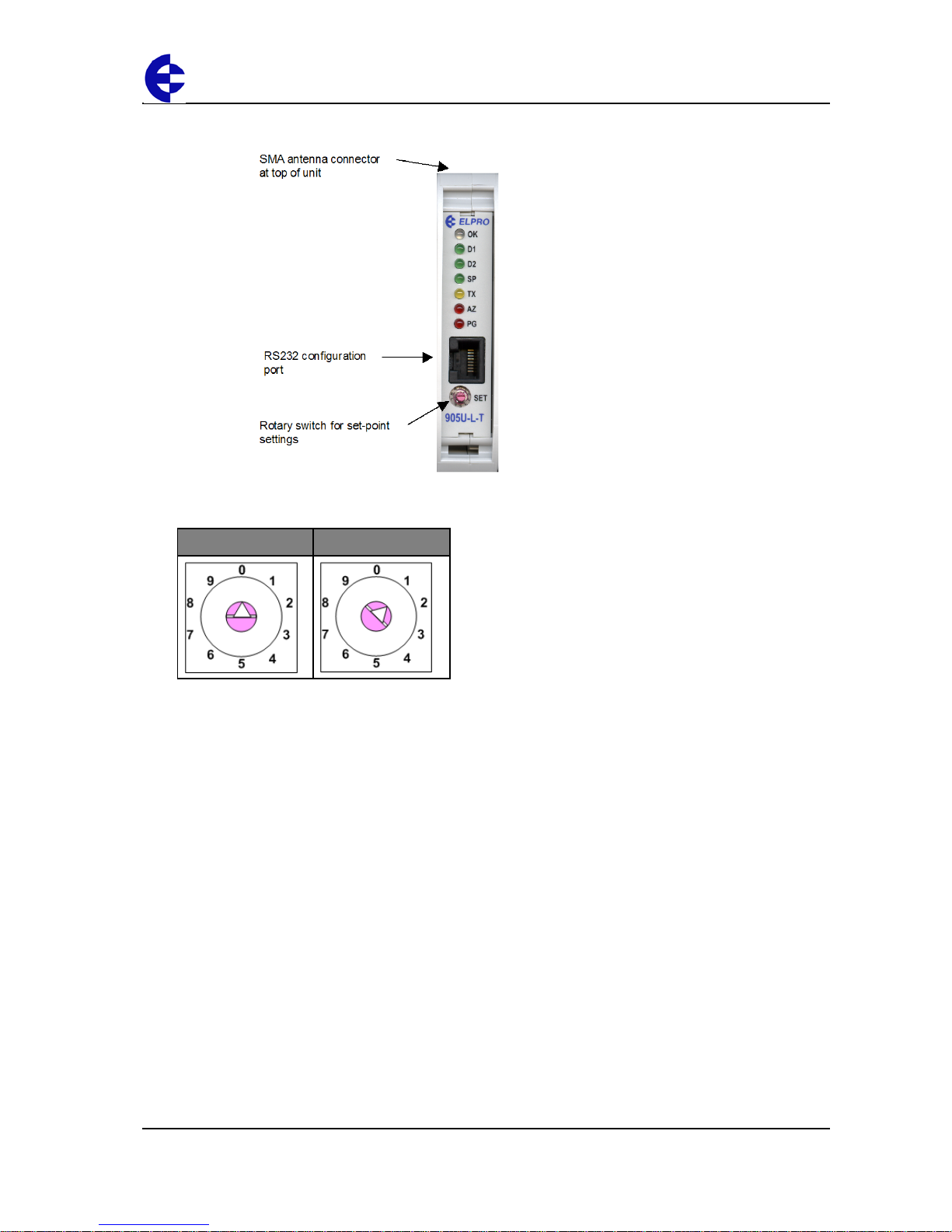
The front panel contains the following components:
The triangle on the rotary switch indicates the current position, for example:
Position 0 Position 1
NOTE: To avoid damaging the rotary switch, use a screwdriver to change the position.
The rotary switch controls the setpoint levels on the Analog and Thermocouple inputs.
Page 8
105U-L Wireless I/O Installation Manual
105U-L Wireless I/O Page 8 of 38
Version 1.8
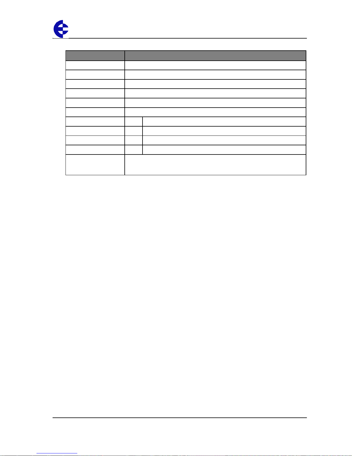
The LEDs on the front panel indicate the unit status:
LED Status Indicates
None
No power supply.
OK LED Green
Current status of the unit OK.
OK LED Red
Fault condition detected in unit.
TX Led Flashes
Transmitting Message.
PG LED on
Configuration Cable Connected.
Input LED ON
Input LEDS (i.e. D1, D2, SP, AZ.) light when the corresponding input is active.
D1 Digital Input 1 is active (Low).
D2 Digital Input 2 is active.
SP Analog Setpoint is active.
AZ Analog Input is zero mA
All LEDs medium flash
Medium speed flash (1.6HZ) indicates the module is halfway through the
configuration process. Medium flash also happens when you set the rotary switch
to position 0 when powering on the unit.
Page 9
105U-L Wireless I/O Installation Manual
105U-L Wireless I/O Page 9 of 38
Version 1.8
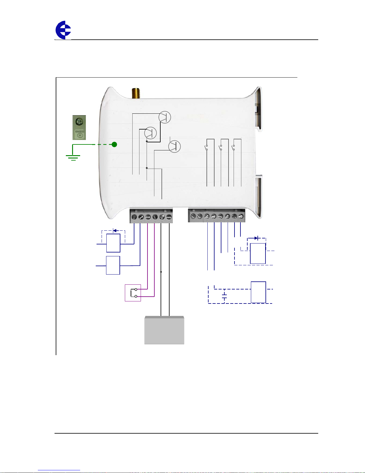
Receiver unit
Your 105U-L-R unit has the following components and terminal connections:
Max. 30VDC
500mA
+
For inductive load,
use surge diodes
+
LOAD
LOAD
-
+
SYSTEM OK
COMMS FAIL
COMMON
AO
POWER SUPPLY
+
24V
ANALOG OUTPUT
Max. analog load
900 ohm
-
+
DO 3
DO 3
DO 2
DO 1
DO contacts are rated at 1A, 250VAC
For good engineering practice, use
a surge diode for DC loads and
a surge capacitor (10nF 250V) for AC loads
DC
LOAD
AC
LOAD
+
-
POWER SUPPLY
9 – 30 VDC
250mA @ 12V
125mA @ 24V
DO 1
DO 2
- NOT USED
-
-
-
-
-
-
-
Page 10
105U-L Wireless I/O Installation Manual
105U-L Wireless I/O Page 10 of 38
Version 1.8
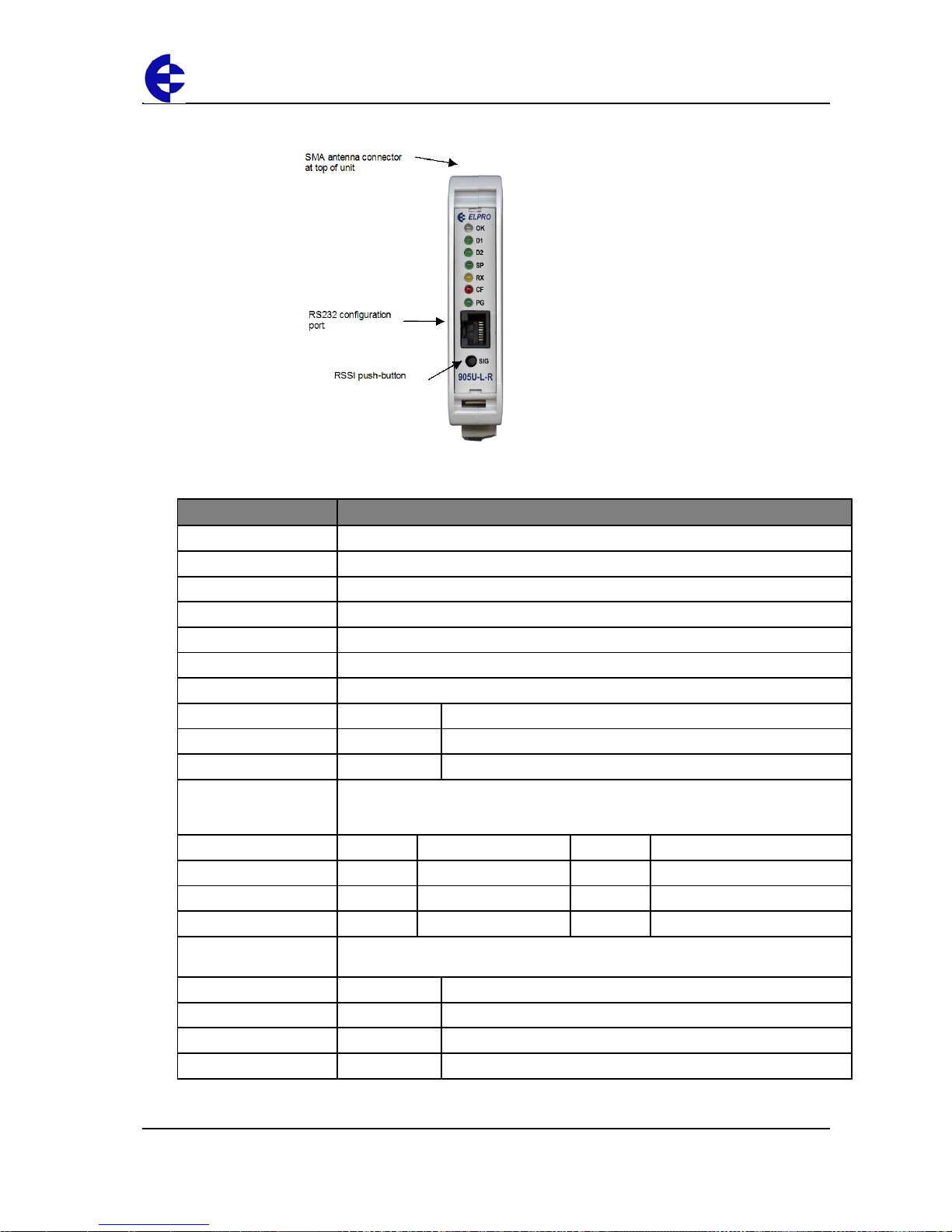
The front panel contains the following components:
The LEDs on the front panel indicate the unit status:
LED Status Indicates
None
No power supply.
OK LED Green
Current status of the unit OK.
OK LED Red
Fault condition detected in unit.
RX Led Flashes
Receiving Message.
CF Led ON
Module Communication Failure Output is active.
PG LED on
Configuration Cable Connected.
Output LED ON
The Output LEDS (i.e. D1, D2, D3) light when the corresponding output is active.
D1 Relay output D1 is ON (Contact Closed).
D2 Relay Output D2 is ON.
D3 Relay Output D3 is ON.
LEDs with RSSI Push
Button Pressed
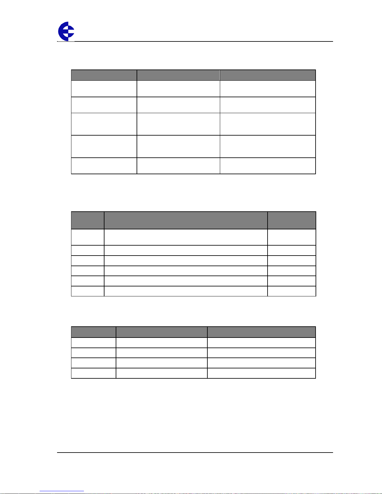
When you press the RSSI push button, the unit shows the signal strength by lighting
the LEDs from the bottom to the top. Signal strength is the strength of the last
message received that was addressed to this station.
LED Signal Strength LED Signal Strength
D1 More than -85 dBm RX More than -100 dBm
D2 More than -90 dBm CF More than -105 dBm
D3 More than -95 dBm PG Always on during RSSI test
Output LED flashing
quickly
If an output is in communication failure, the corresponding LED flashes at 5 Hz.
D1 Relay Output D1 is in communication failure.
D2 Relay Output D2 is in communication failure.
D3 Relay Output D3 is in communication failure.
PG Analog output is in communications failure .
Page 11
105U-L Wireless I/O Installation Manual
105U-L Wireless I/O Page 11 of 38
Version 1.8
Installing the antenna
This section explains how to install your antenna and contains the following sections:
Section Description For more information, see …
Supported antennas
and cables
Details the antennas and cables
you can use with the units.
Supported antennas on page 11.
Radio transmission
distances
Details the distances for reliable
operation.
Radio transmission distances on page
13.
Installing and earthing
antennas
Details important information
about installing and earthing
antennas.
Installing and earthing antennas on
page 14
Dipole and collinear
antennas
Details important information
about using dipole and collinear
antennas.
Dipole and collinear antennas on
page 15.
Yagi antennas
Details important information
about using Yagi antennas.
Yagi antennas on page 17.
For more information, see the next sections.
Supported antennas
You can use the following antennas with the units:
Antenna Additional information Total gain
(including cable)
WH900
Whip antenna for mounting directly onto the module - operation up
to ½ mile (1 km).
-6 dBi
CFD890EL
0 dBi Dipole antenna with 15’ of Cellfoil cable and SMA connector. 0 dBi
SG900EL
5dBi Collinear omni-directional antenna with N-type connecto r. 5 dBi
SG900-6
8dBi Collinear omni-directional antenna with N-type connecto r. 8 dBi
YU6/900
10dBi Yagi directional antenna with N-type connector. 10 dBi
YU16/900
15dBi Yagi directional antenna with N-type connector. 15 dBi
You can use the following cables with the units:
The following table shows compatible cables for different antennas when used with the
105U-L-T:
Antenna North America Australia/NZ
SG900EL
Any cable. CC10 or CC20.
SG900-6
Any cable. CC20.
YU6/900
CC20. External cable with loss > 9dB.
YU16/900
External cable with loss > 9dB. External cable with loss > 15 dB
Page 12
105U-L Wireless I/O Installation Manual
105U-L Wireless I/O Page 12 of 38
Version 1.8
You must carefully select antennas for 105U-L-T modules to avoid contravening the
maximum power limit on the unlicensed channel. The net gain of the antenna/cable
configuration should be no more than 6dB in North America (USA, Canada, Mexico) and
no more than 0 dB in Australia / New Zealand.
Note
The net gain of an antenna/cable configuration is the gain of the antenna (in dBi)
less the loss in the coaxial cable (in dB).
For example, an SG900-6 antenna with a CC20/900 cable has a net gain of 2dB (i.e.
+8 dB – 6 dB) at 900 MHz.
The 105U-L-R module has no limitation on antenna gain, as this module does not
incorporate a radio transmitter.
The following table details the gains of some typical antennas:
Antenna Gain (dBi)
Dipole with integral 3m cable
0
Dipole without cable
2
5dBi Collinear (3dBd)
5
8dBi Collinear (6dBd)
8
3 element Yagi
5
6 element Yagi
10
The following table details losses for typical cables:
Cable Loss (dB per 10m)
at 900 MHz
RG58
-5
RG213
-2.5
Cellfoil
-3
Page 13
105U-L Wireless I/O Installation Manual
105U-L Wireless I/O Page 13 of 38
Version 1.8
Radio trans mission distances
The unit will operate reliably over large distances depending on the:
Antenna type;
Antenna location;
Amount of radio interference; and
Radio path obstructions (e.g. hills or trees).
Typical reliable distances are:
Area Distance Additional information
USA/Canada
20+ miles 6dB net gain antenna configuration permitted (4W Equivalent RF power permitted).
Australia/NZ
20+ km Unity gain antenna configuration (1W Equivalent RF power permitted).
To achieve these distance, you must elevate at least one site on a hill or transmission
tower.
Modules will operate reliably with some radio path obstruction; however obstructions also
reduce the reliable distance.
Note
You must test all obstructed paths to check the reliability of the path.
You can achieve maximum transmission distances if the radio path has “line of sight”. For
example, raising antennas above intermediate obstructions including hills, trees, etc.
Obstructions reduce the range; however they may not prevent a reliable path.
The closer the obstruction is to the antenna, the greater the blocking effect. For example,
a group of trees around the antenna is a larger obstruction than a group of trees further
away from the antenna. You can achieve longer distances by mounting one antenna on
top of a hill.
Note
Due to the earth’s curvature, you must elevate antennas higher than the ground
level between the antennas for longer paths (greater than 3 miles / 5 km).
The unit can tolerate larger amounts of obstructions for shorter distances. For very short
distances, you can also mount the antennas inside buildings.
If two 105 modules cannot communicate reliably, you can use a third 105 module as a
“repeater” to receive and re-transmit messages. This module may also have input/output
(I/O) signals connected to it and form part of the I/O network.
Note
1. ELPRO recommends using the 105-G module as a repeater unit between 105UL-T and 105U-L-R modules.
2. To use a repeater unit, the 105U-L modules and the repeater module must be
configured using the supplied configuration software. The factory default
configuration described in the Quick Start Guide cannot use a repeater unit.
Page 14
105U-L Wireless I/O Installation Manual
105U-L Wireless I/O Page 14 of 38
Version 1.8
Installing and earthing antennas
You must connect an antenna to each 105 module using the SMA connector at the top of
the enclosure.
ELPRO recommends carefully taping the connections between the antenna and coaxial
cable to prevent moisture ingress. Moisture ingress in the coaxial cable is a common
cause of radio system problem as it greatly increases the radio losses.
ELPRO recommends taping the connection with three layers of tape:
Layer Tape
1
PVC tape.
2
Vulcanising tape (e.g. 3M 23 tape).
3
Additional layer of PVC UV-stabilized insulating tape.
The first tape layer lets you easily inspect the joint if required as you can easily remove
the vulcanising seal.
Note
You must effectively earth all masts for mast-mounted antennas to avoid lightning
surges. We also recommend using a coaxial surge diverter for antennas mounted
outside industrial plant environments.
If the antenna is not already shielded from lightning strike by an adjacent earthed
structure, you can provide shielding by installing a lightning rod above the antenna.
You should connect the antenna to the module using 50 ohm coaxial cable (e.g. RG58 or
RG213) terminated with a male coaxial connector, The higher the antenna is mounted, the
greater the transmission range; however as the length of coaxial cable increases so do
cable losses. For use on unlicensed frequency channels, there are several types of
antenna suitable for use.
If you mount antennas on elevated masts, you should effectively earth the masts to avoid
lightening surges. The 105U-L radios are fitted with surge protection.
Note
For high lightening risk areas, ELPRO recommends additional surge suppression
devices. If the antenna is not already shielded from lightening strike by an adjacent
earthed structure, you can install a lightening rod to provide shielding.
Page 15

105U-L Wireless I/O Installation Manual
105U-L Wireless I/O Page 15 of 38
Version 1.8
Dipole and collinear antennas
This section contains important information for using dipole and collinear antennas. For
more information, see the next sections.
Dipole antennas
Unity gain dipole antennas are commonly used on unlicensed channels. The dipole
antenna does not provide any gain, so the power transmitted from the antenna is the
same as the power out of the module.
A dipole antenna that comes supplied with integral 15 ft cable does not require additional
coaxial cable.
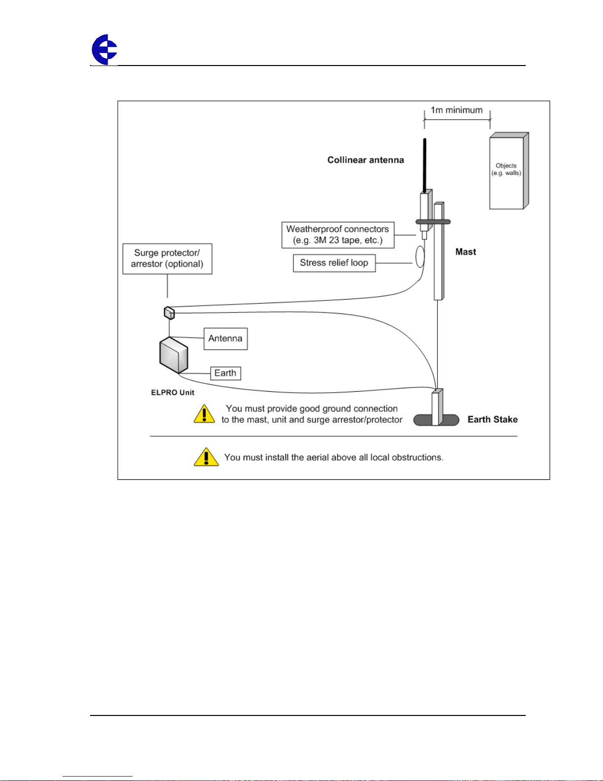
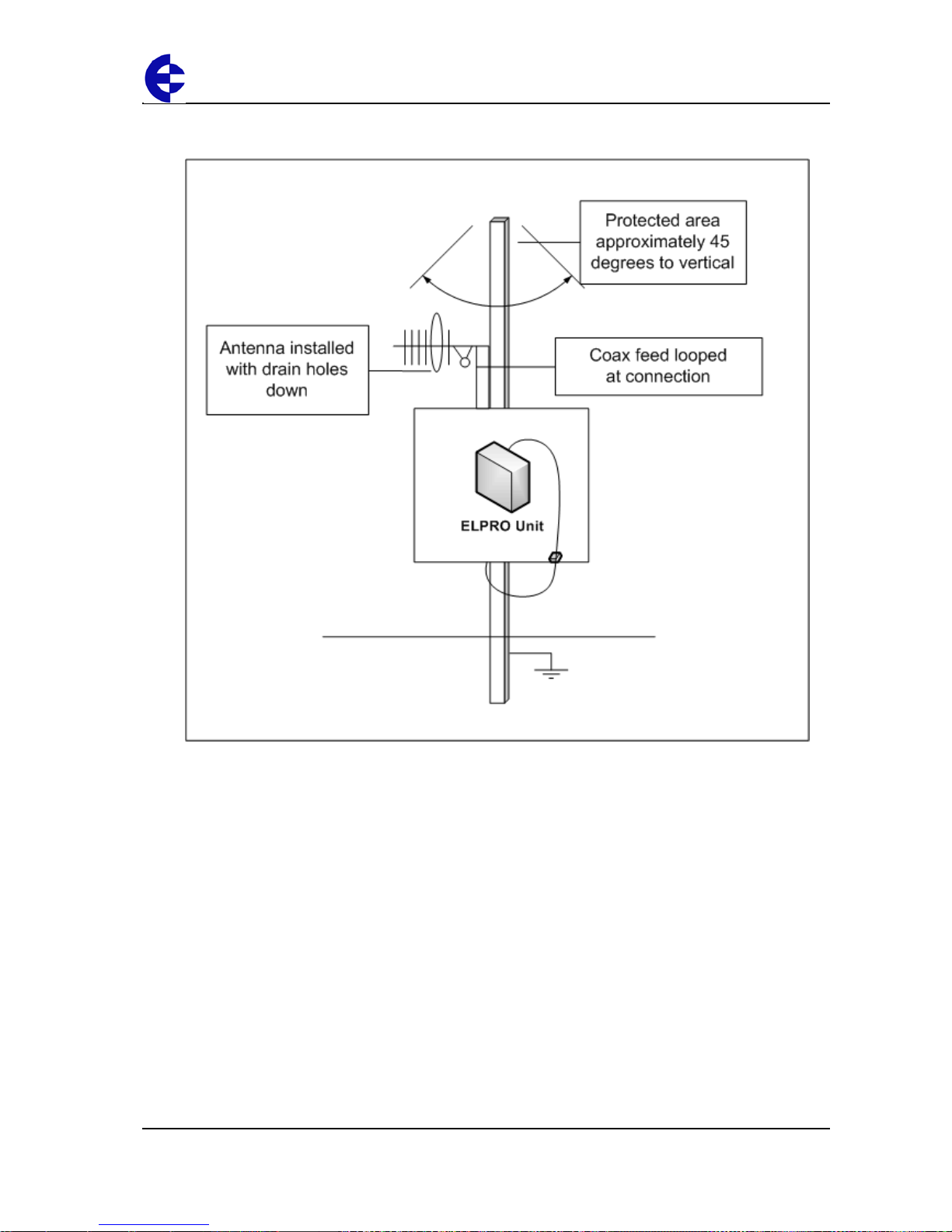
You should mount dipole antennas vertically, preferably no less than 1 metre away from a
wall or mast for maximum performance.
Collinear antennas
Collinear antennas transmit the same amount of radio power in all directions horizontally,
and are easy to install and use. They provide gain by compressing the radiated signal to a
flattened disc shape, and reducing the amount of signal radiated above and below the
horizontal plane.
Collinear antennas are generally used at a central site with more than one remote site, or
at a repeater site.
Collinear antennas are similar in appearance to dipole antennas; however the antenna is
longer.
Collinear antennas are supplied without cable, and require additional coaxial cable.
You can use collinear antennas to:
Transmitter – to compensate for the losses in long lengths of coaxial cable.
Receiver – to increase receive sensitivity.
Page 16
105U-L Wireless I/O Installation Manual
105U-L Wireless I/O Page 16 of 38
Version 1.8
The following diagrams shows the recommended installation for collinear and dipole
antennas:
Page 17
105U-L Wireless I/O Installation Manual
105U-L Wireless I/O Page 17 of 38
Version 1.8
Yagi antennas
Yagi antennas are directional and have positive gain to the front of the antenna and
negative gain in other directions. You can use the gain to:
Compensate for coaxial cable loss for transmitter unit; and
Increase receive sensitivity for receiver units.
You should install Yagi antennas with the central beam horizontal and pointed directly in
the transmission direction to benefit from the antenna gain.
Note
Yagi antennas usually have a drain hole on the folded element. You should position
the drain hole at the bottom when installing the antenna.
You can install Yagi antennas:
Vertically polarized – with the elements in a vertical plane; or
Horizontally polarized – with the elements in a horizontal plane.
The following table shows the recommended installation mode for different situations.
If your installation has … ELPRO recommends using …
Two stations both using Yagi antennas
• Horiz ont al pol ariz ati on for the stati on s.
Two or more stations communicating with
a common station
• Vertical polarization for the stations; and
• Dipole or collinear (i.e. non-directional) antenna for the
central station.
Page 18
105U-L Wireless I/O Installation Manual
105U-L Wireless I/O Page 18 of 38
Version 1.8
The following diagrams shows the recommended installation for collinear and dipole
antennas:
Page 19
105U-L Wireless I/O Installation Manual
105U-L Wireless I/O Page 19 of 38
Version 1.8
Installing the power supply
The unit works with a 9-30 VDC 0.6 Amp CSA certified Class 2 power supply. For use in
Class 1 Div 2 explosive areas, the power supply must be approved for Class 1 Div 2 use.
Warning – explosion hazard
Do not disconnect while circuit is live unless area is known to be non-hazardous.
The following table shows the power supply requirements :
Power supply 105U-L-T 105U-L-R
12V 600 mA 250 mA
24V 300 mA 125 mA
The power supply can be a floating supply or negatively grounded.
The transmitter provides a 24V DC regulated supply for analog loop power. The supply is
rated at 35 mA and should ONLY be used for powering analog loops.
To install the power supply:
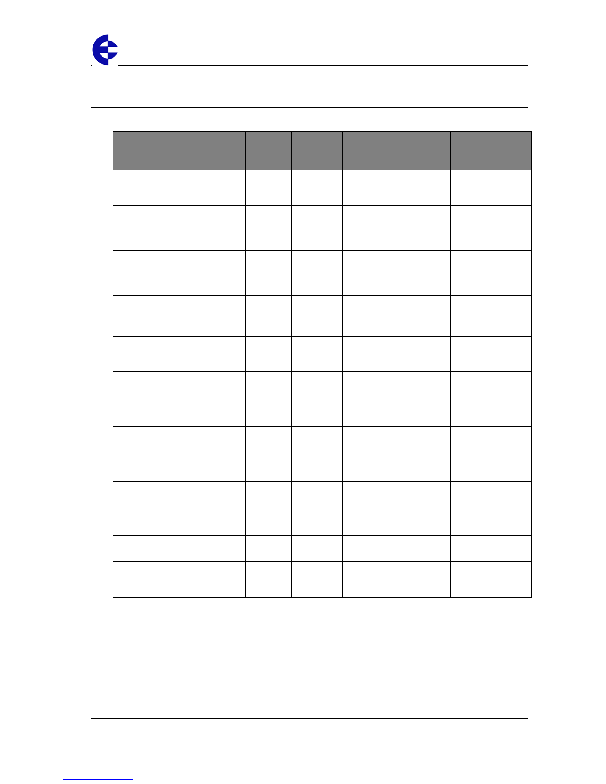
1. Connect the positive lead to Power Supply Input.
2. Connect the negative lead to Ground.
Note
To ensure internal surge protection works correctly, you must earth each unit using
the Earth terminal.
You should connect the module to the same ground/earth point as the antenna
mounting to avoid differences in earth potential during voltage surges.
Do NOT connect the positive side of the supply to Earth.
3. The following diagram illustrates the connection:
Ground
Page 20
105U-L Wireless I/O Installation Manual
105U-L Wireless I/O Page 20 of 38
Version 1.8
Inputs and outputs
The units have the following inputs and outputs:
Input/output 105U-L-T 105U-L-R Description For more
information, see
…
Digital inputs
2
Suitable for Voltage free
contact, NPN transistor,
0-5V signal.
Digital inputs on
page 21.
Relay outputs
3
250VAC 1A / 30VDC 1A. Relay outputs
Important
Information on
page 22.
Status outputs
2 2
Max 30VDC, 500 mA.
Indicate module status,
communication failure
and local setpoint status.
Status outputs on
page 23.
Analog inputs
1
4-20 mA with over-range
and under-range.
0-10 mA with over-range.
Analog input on
page 24.
+24V Loop supply
1
Provides power for 1
external current loop (up
to 35 mA).
Installing the
power supply on
page 19.
Analogue setpoint
1
Allows discrete setpoint to
be controlled from analog
input. Threshold
adjustable via rotary
switch.
Refer to the User
Manual.
Thermocouple / millivolt input
1
Provides measurement of
E, J, K, T type
Thermocouple, millivolt
signals and user-defined
thermocouple types.
Thermocouple
input on page 27
Thermocouple setpoint
1
Lets you control discrete
setpoint from
thermocouple with
threshold adjustable via
rotary switch.
Refer to the User
Manual.
Pulse inputs
2
Up to 10Hz. Pulse input on
page 28.
Analog output
1
0-22 mA, suitable for loop
powered, floating input or
single-ended input device.
Analog output on
page 29.
For more information, see the next sections.
Page 21
105U-L Wireless I/O Installation Manual
105U-L Wireless I/O Page 21 of 38
Version 1.8
Digital inpu ts
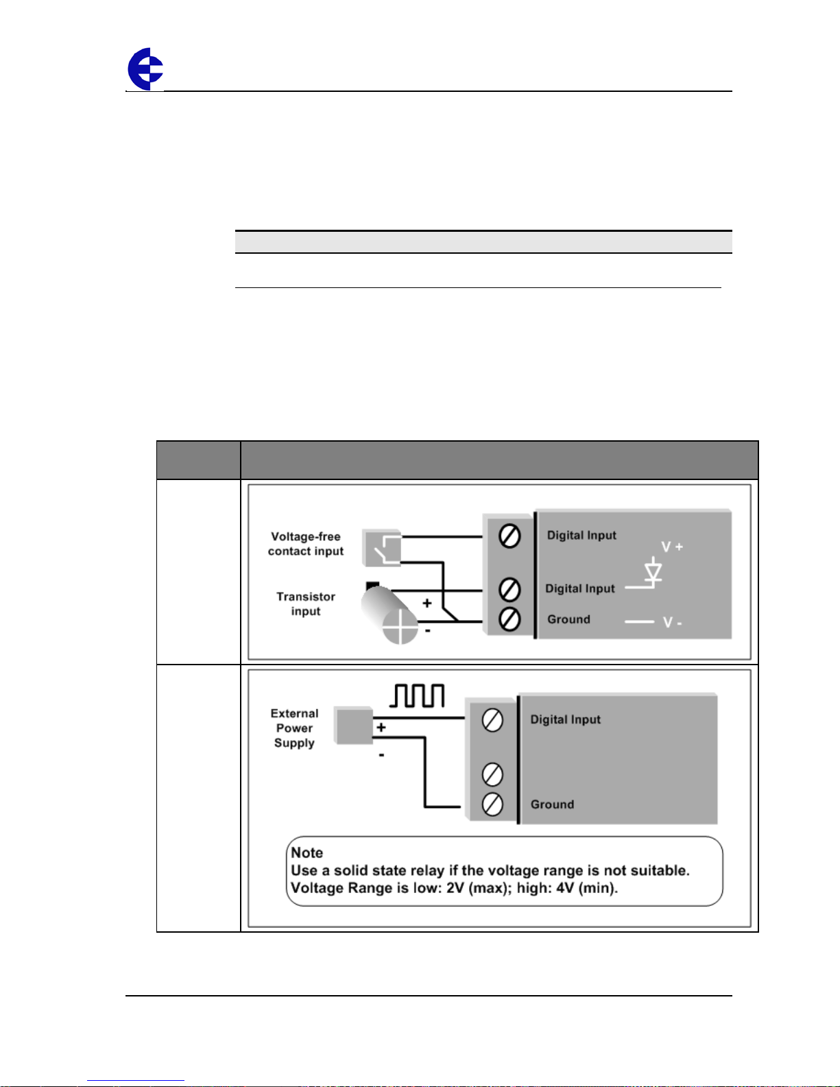
The 105U-L-T module provides two digital inputs suitable for:
Voltage free contacts – e.g. mechanical switches; or
NPN transistor devices – e.g. electronic proximity switches; or
0-5V signals - 2V – 4V Minimum range.
Note
PNP transistor devices are not suitable.
The unit provides contact wetting current of approximately 5mA to maintain reliable
operation of driving relays.
Each digital input is connected between the appropriate Digital Input terminal and
Ground.
Each digital input circuit includes a LED indicator that lights when the digital input is active
(i.e. when the input circuit is closed).
To activate the digital input, the switching device resistance must be less than 200 ohms.
Connection
method
Example
Voltage free
contact
Active 0-5v
signal
device
Page 22
105U-L Wireless I/O Installation Manual
105U-L Wireless I/O Page 22 of 38
Version 1.8
Relay outputs
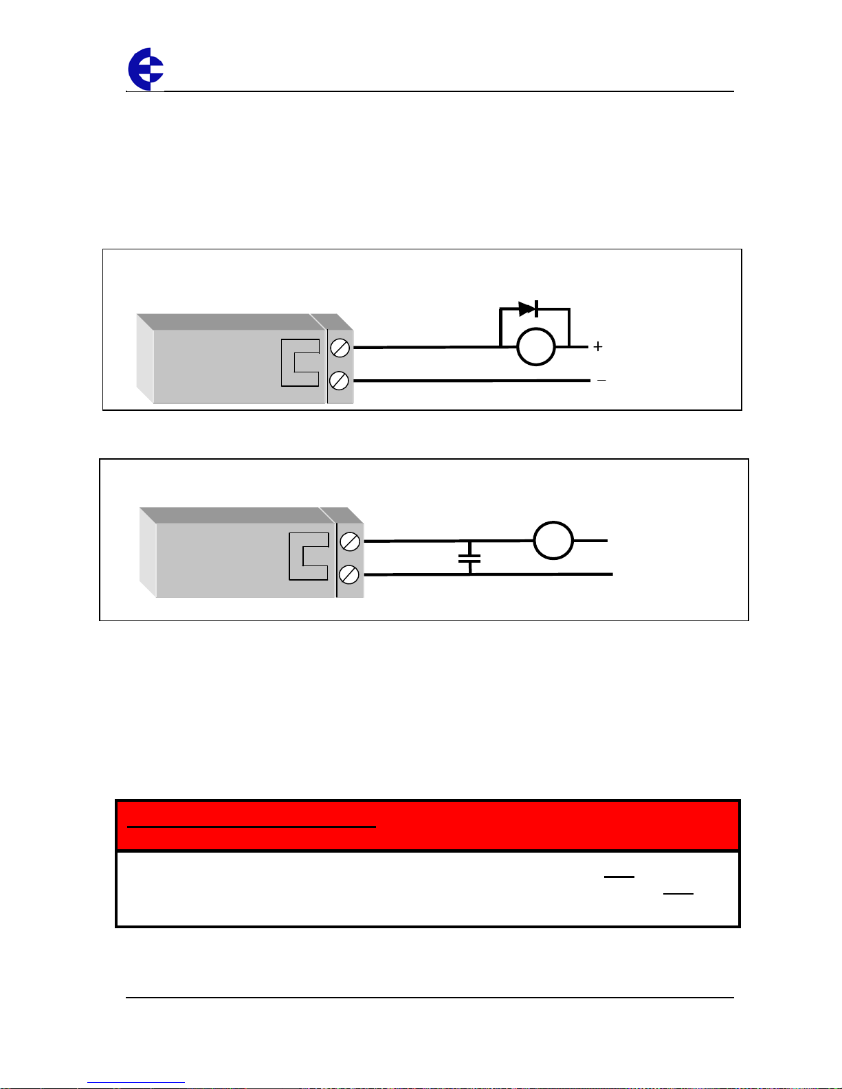
The 105U-L-R module provides three normally open voltage-free relay contacts rated at
250VAC / 30VDC 1A.
You can use these outputs to directly control low-powered equipment or power larger
relays for higher-powered equipment.
For inductive loads, ELPRO recommends:
DC relays - use flyback diodes across the external circuit to prevent arcing across the relay
contacts.
AC relays – use capacitors (e.g. 10nf 250V) to prevent arcing across the relay contacts.
You can individually configure digital outputs to turn off if no command message is
received by the output for a certain period. This feature provides an intelligent watchdog
for each output, so communications failure at a transmitting site causes the output to
revert to a known state.
The output circuit is connected to the appropriate pair of Digital Output terminals. Each
digital output circuit includes a LED indicator that lights when the digital output is active.
The LED flashes if the watchdog alarm is active.
AC
Load
Max 250VAC 1A
10nF
250V
DC
Load
Max 30VDC
In order to comply with Electrical Safety Standards, when connecting SELV AND voltages
which are greater than SELV (30VAC or 60VDC) together, then Relay Output 2 must NOT
be
used in order to provide sufficient isolation between the outputs
IMPORTANT SAFETY INFORMATION
Page 23
105U-L Wireless I/O Installation Manual
105U-L Wireless I/O Page 23 of 38
Version 1.8
Status outputs
The unit contains the following status outputs:
System OK;
Setpoint Output; and
Communications Failure.
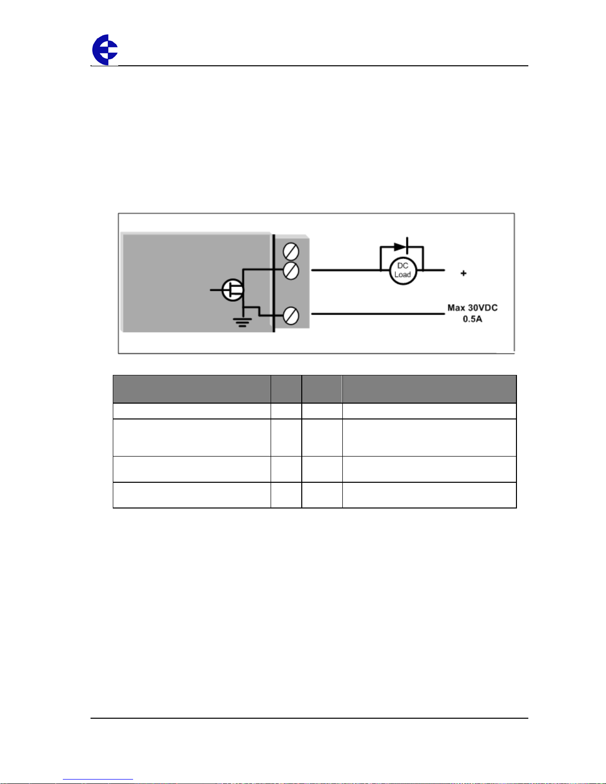
Status outputs are FET output to common rated at 30VDC 500 mA.
Connect the output circuit to the appropriate Status Output terminal. Each status output
circuit is associated with an LED indicator that lights lit when the digital output is active.
The following table details the status output behavior:
Status output LED LED
status
Description
System OK active (both modules)
OK Green No fault detected
System OK inactive
OK Red
• Interna l fa ult detected.
• Supply voltage Low
•
Analog Loop supply overloaded
Setpoint Output (105U-L-T)
SP Green Local setpoint attached to 4-20mA analog
input.
Communications Failure (105U-L-R)
CF Red Watchdog alarms active on digital outputs
or analog outputs.
Page 24

105U-L Wireless I/O Installation Manual
105U-L Wireless I/O Page 24 of 38
Version 1.8
Analog input
The 105U-L-T module provides one 0 - 20 mA DC analog input for connecting to
instrument transducers (e.g. level, moisture, pressure transducers, etc.).
Note
The 105U-L -T module inputs measure down to 0mA and can also be used for zero
based signals (e.g. 0 - 1 0 mA).
The analog input has a positive and negative terminal and can be placed at any point in
the current loop, providing neither input rises above the 24 volt Analog Loop Supply
level.
Each input has a loop resistance of less than 250 ohms and zener diode protection is
provided against over-voltage and reverse voltage.
Note
You may require additi onal protection in high voltage or noisy environments or for
long wiring runs.
A 24VDC loop supply is available on the 105U-L-T module for powering the analog
transducer loops. In this situation, connect the:
Analog loop - between an Analog Input (-) terminal and Ground.
Positive terminal – i.e. Analog Input (+) to the +24V Analog Loop Supply.
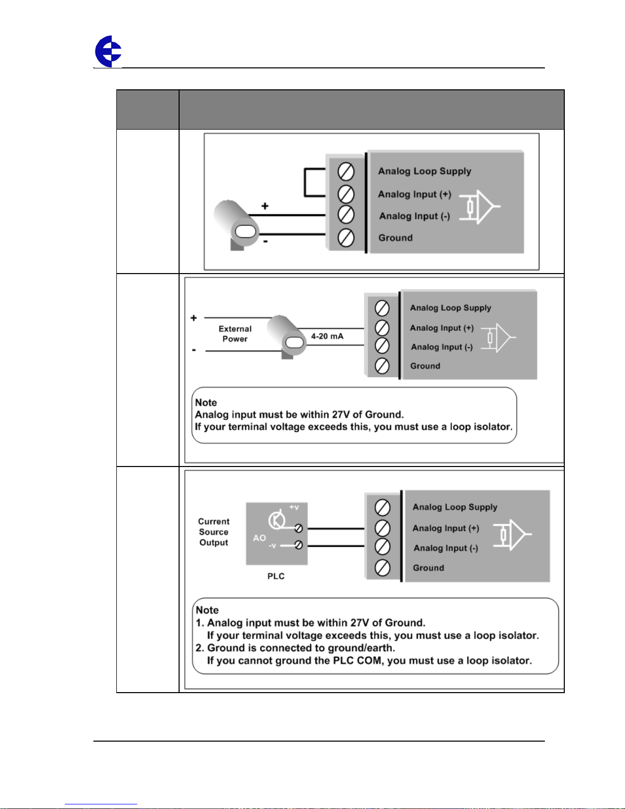
Externally powered loops may be connected by connecting the input between "Analog
Input (+)" and “Analog Input (-)” Common mode voltage may be -0.5V to 27V.
ELPRO recommends using shielded cable for analog I/O loops to minimize induced noise
and Radio Frequency Interference (RFI).
Note
You should only connect one end of the cable shield to Earth
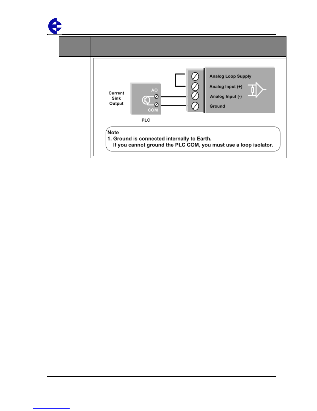
To connect an analog signal from a PLC or DCS output to an analog input on the 105U-LT, you must carefully check the internal circuit of the output as different devices use
different ways to create an analog signal.
Page 25
105U-L Wireless I/O Installation Manual
105U-L Wireless I/O Page 25 of 38
Version 1.8
The following diagrams illustrate different connection methods:
Analog
signal
source
Example
2 wire
transducer
4 wire
transducer
Current
source
output
Page 26
105U-L Wireless I/O Installation Manual
105U-L Wireless I/O Page 26 of 38
Version 1.8
Analog
signal
source
Example
Current sink
output
Page 27
105U-L Wireless I/O Installation Manual
105U-L Wireless I/O Page 27 of 38
Version 1.8
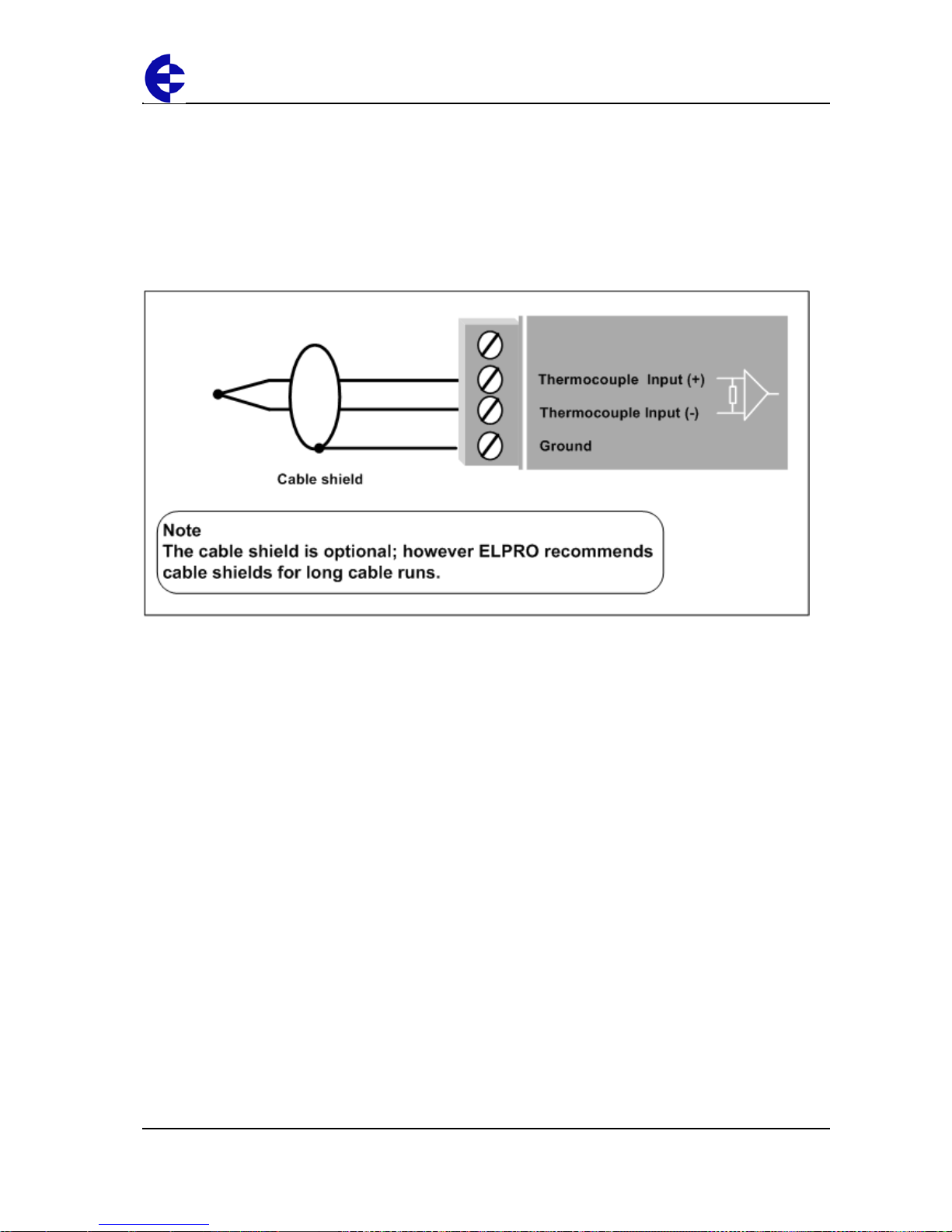
Thermocouple input
The 105U-L-T provides one input suitable for connection to a thermocouple or a millivolt level
signal. The module provides linearization tables for J, K and T type thermocouples and also
supports other types via a user linearization table.
Millivolt signals in the range -10mV to +100 mV a r e supported.
For more information on configuring the thermocouple input and cold-junction compensation to
suit your application, refer to the User Manual.
Page 28
105U-L Wireless I/O Installation Manual
105U-L Wireless I/O Page 28 of 38
Version 1.8
Pulse input
The 105U-L-T module lets you configure the digital inputs as pulse inputs with the
following characteris tics:
Characteristic Value
Maximum rate
10 Hz
Minimum off time
20 mSec
Minimum on time
20 mSec
Using this mode, you can map the pulse count to a remote output by transmitting the
pulse count to a 105-G module register or re-generating as a Pulse Output on 105-1 or
Digital Output on a 105-3 unit.
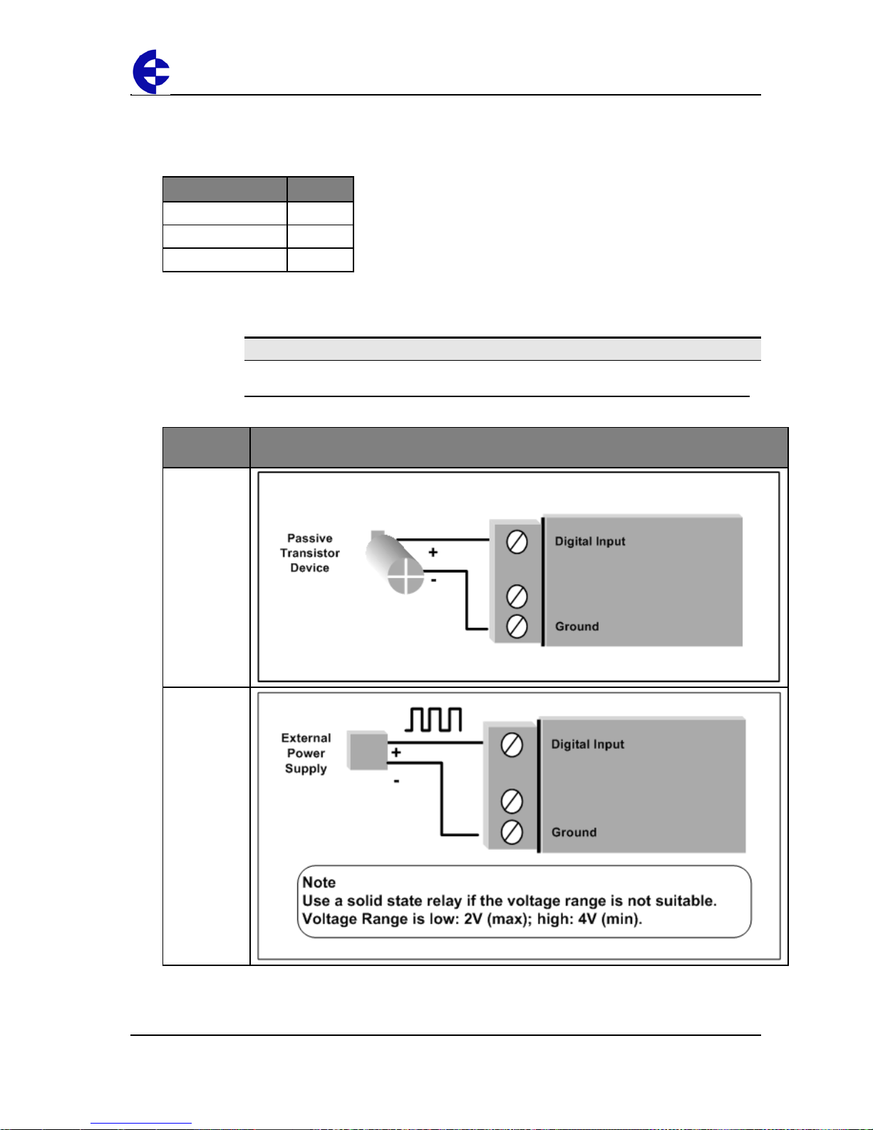
Note
You should connect the pulse input in the same way as a digital input.
The following diagrams illustrate different connection methods:
Connection
method
Example
Passive
transistor
Active pulse
device
Page 29
105U-L Wireless I/O Installation Manual
105U-L Wireless I/O Page 29 of 38
Version 1.8
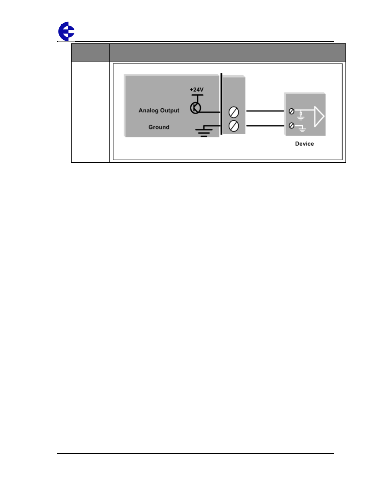
Analog output
The 105U-L-R module provides a 4 - 20 mA DC analog output for connecting to
instrument indicators to display remote analog measurements. The analog output is a
current source provided from an internally generated +24V loop supply.
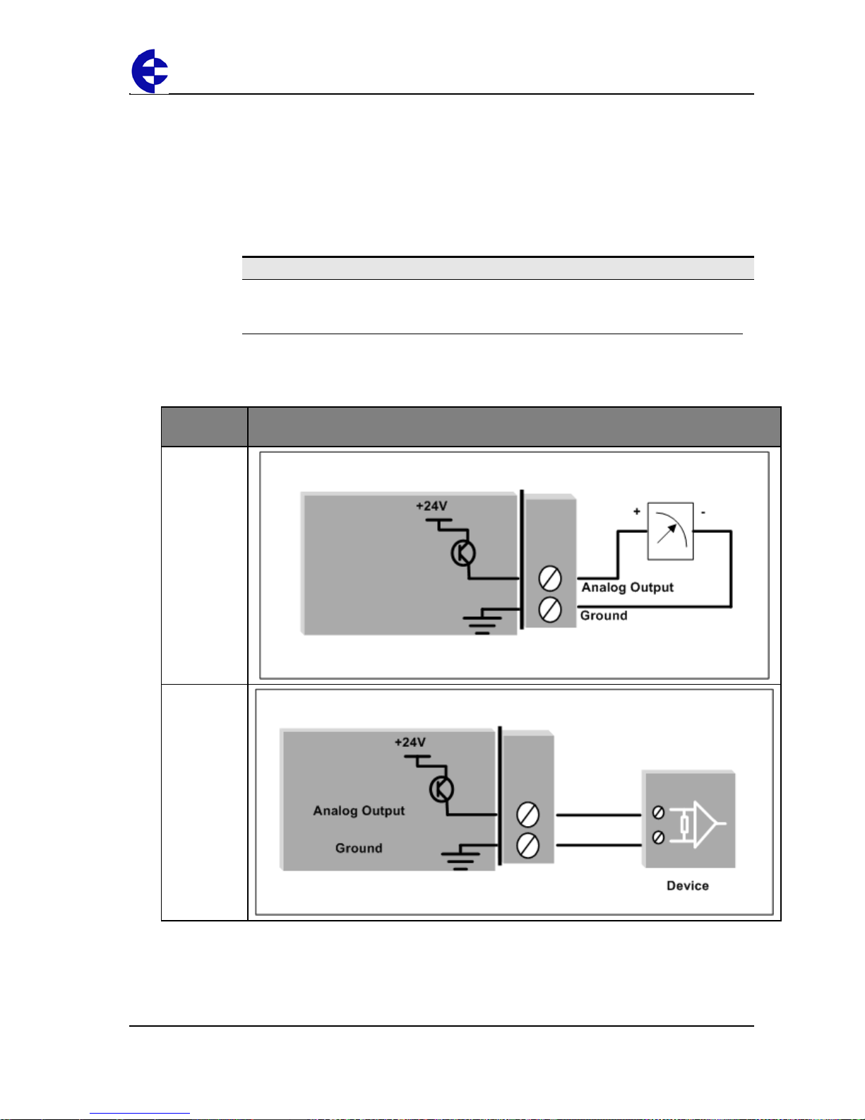
When connecting to an external device (e.g. electronic indicator, recorder, PLC / DCS
input, etc.) by connecting the output between the Analog Output terminal (+) and the
COM terminal (-).
Note
Zener protection of analog outputs provides protection against short periods of overvoltage; however longer periods may result in module damage.
You can also individually configure analog outputs to turn off (i.e. 0 mA) if no command
message is received to the output for a certain period.
The following diagrams illustrate different connection methods:
Connection
method
Example
Loop
powered
device
Floating
input device
Page 30
105U-L Wireless I/O Installation Manual
105U-L Wireless I/O Page 30 of 38
Version 1.8
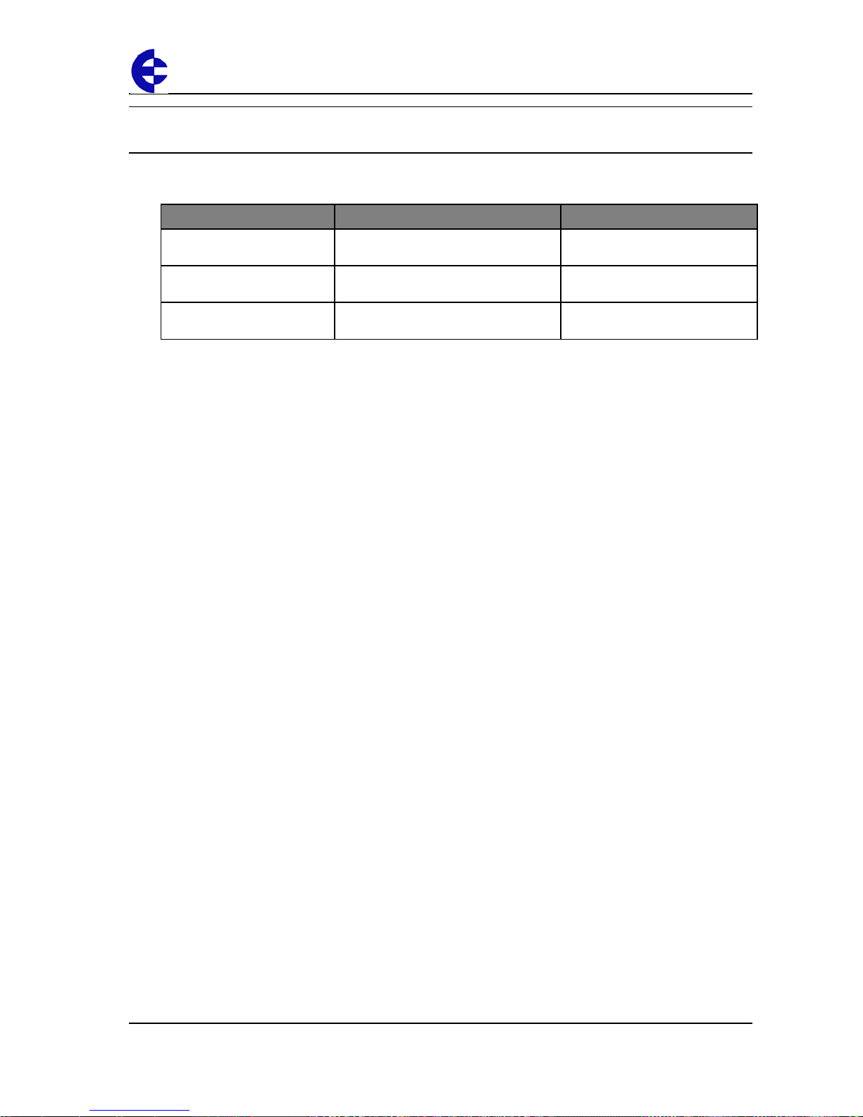
Connection
method
Example
To singleended input
device
Page 31
105U-L Wireless I/O Installation Manual
105U-L Wireless I/O Page 31 of 38
Version 1.8
Installing and configuring the unit
This section describes how to install and configure your unit and contains the following
sections:
Section Description For more information, see …
Installing the unit
Describes how to physically install your
unit.
Installing the unit on page 32.
Configuring your unit
Describes the different ways to
configure your unit.
Configuring your units on page 33.
Testing your unit
Describes ELPRO’s recommendations
for testing your unit.
Testing your units on page 34.
For more information, see the next sections.
Page 32
105U-L Wireless I/O Installation Manual
105U-L Wireless I/O Page 32 of 38
Version 1.8
Installing the unit
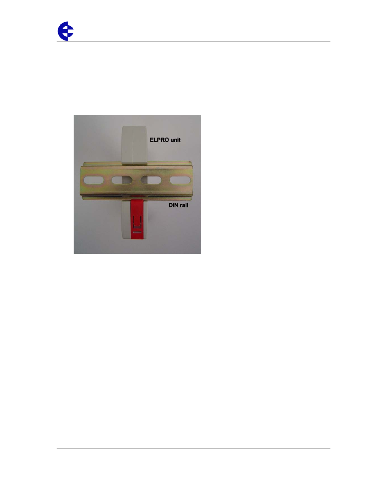
To install the unit:
1. Connect signals to the supplied terminals.
2. Connect the radio antenna.
3. Install DIN rail to mount the module.
4. Clip the module to the DIN rail:
You can now configure your unit. For more information, Configuring your units on page
33.
Page 33
105U-L Wireless I/O Installation Manual
105U-L Wireless I/O Page 33 of 38
Version 1.8
Configuring your units
You can configure your network using:
Default factory configuration – that lets you easily setup your network as a simple
send/receive; or
User-defined customized configuration – that lets you set specific information
about your network and allows communication with other ELPRO 105 series devices.
For more information on setting a user-defined customised configuration, see the User
Manual.
For more information on setting the factory default con figuration, refer to the Quick Start
Guide included with your module.
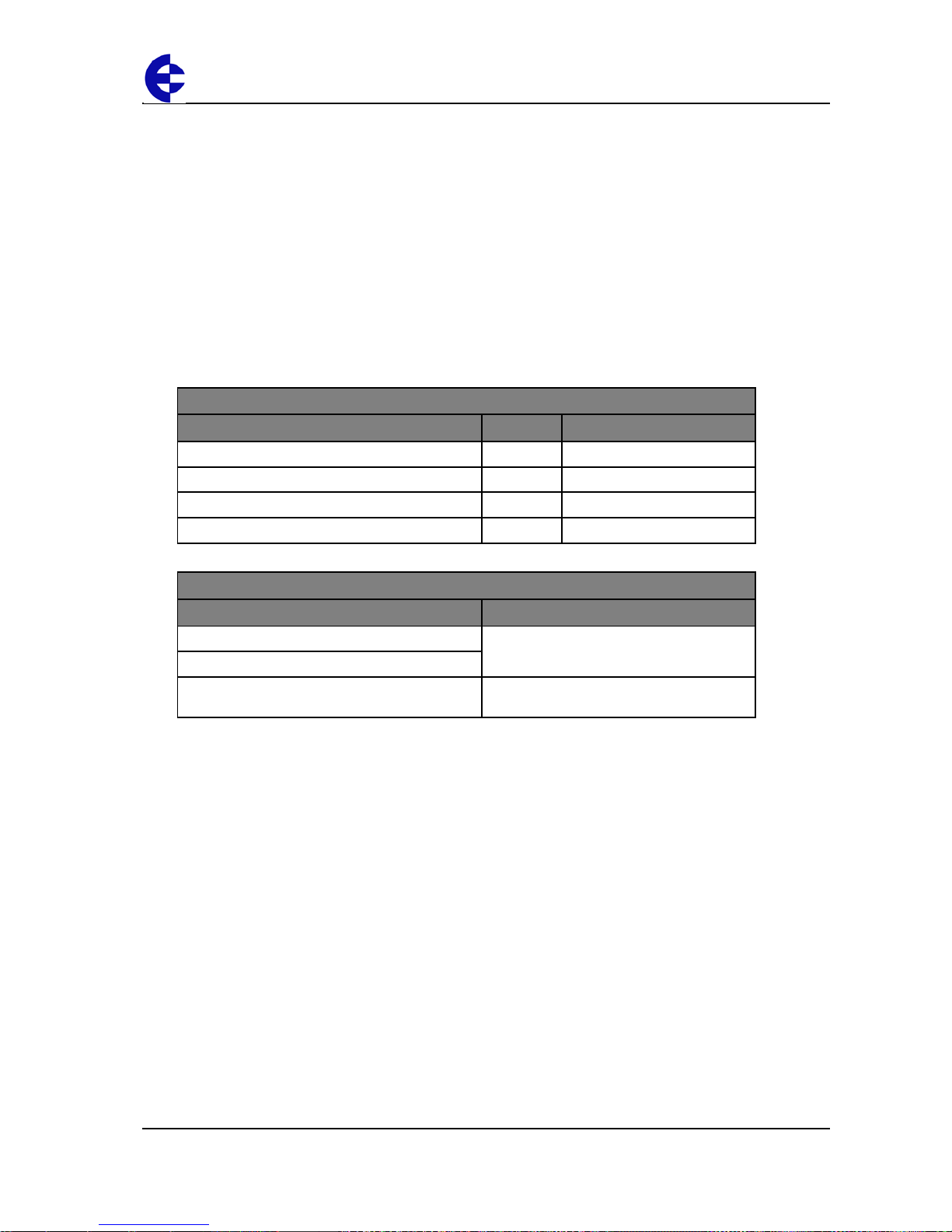
The following table details the factory default configuration:
Signals sent over radio
105U-L-T(Transmitter) Sends 105U-L-R (Receiver)
Digital Input 1
Digital Output 1
Digital Input 2
Digital Output 2
Analog Setpoint
Digital Output 3
Analog input (4-20 mA)
Analog output
Other signals
105U-L-T(Transmitter) 105U-L-R (Receiver)
Thermocouple Input (Not used) Communication Failure
(Comes on if no messages from 105U-L-T)
Setpoint Output (Local indication)
System OK (On if system OK) System OK
(On if system OK)
Page 34
105U-L Wireless I/O Installation Manual
105U-L Wireless I/O Page 34 of 38
Version 1.8
Testing your units
We recommend you bench test the complete system before installing a new system.
Configuration problems are easier to identify and fix when the units are next to each other.
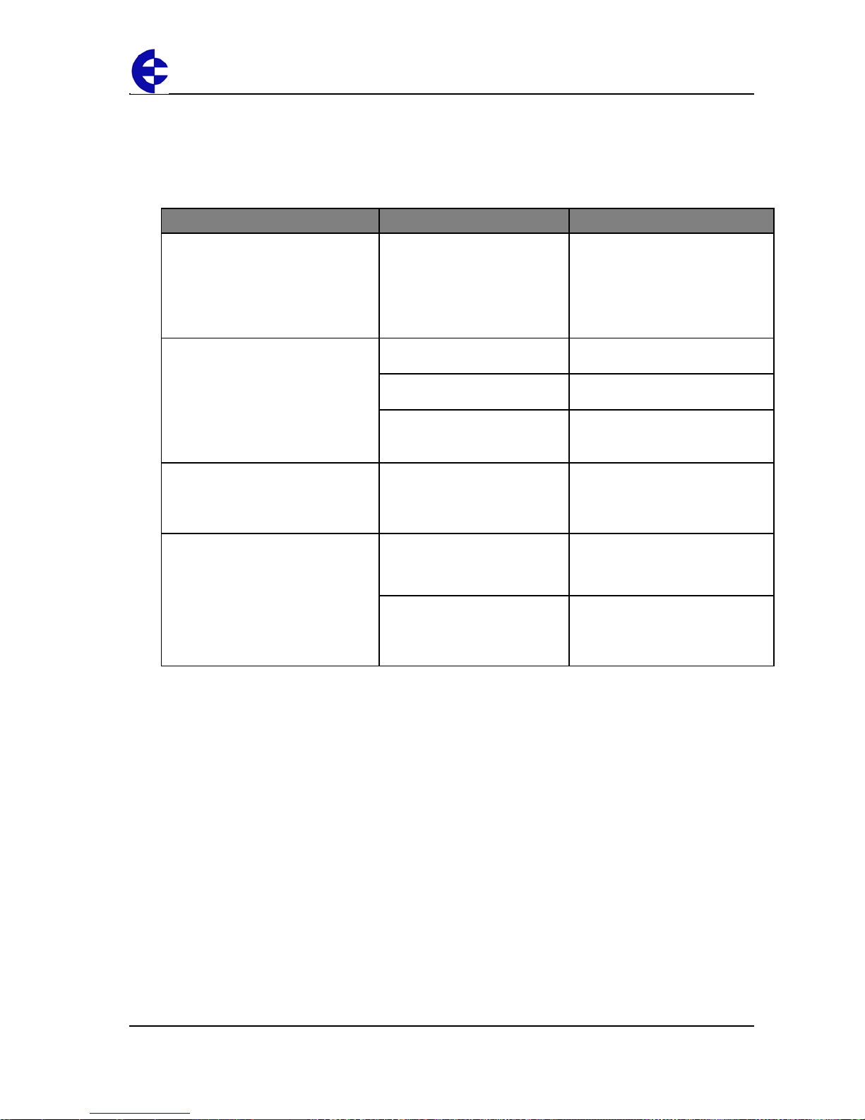
The following table describes common problems and recommended solutions:
If your installation has … You should check … ELPRO recommends …
Poor radio channel
communications
• TX LED flashes but no RX LED
• Output LEDs flash quickly
• The antenna installation.
• For radio interference on the
same channel.
• T he radio path is adequat e.
• Higher per for man ce ante nnas
if the path is too long.
• Higher mounting points to
overcome obstructions.
• Using an intermediate unit as a
repeater.
Red OK LED
• Power Supply voltage • Supply should be between 9
and 30VDC.
• Analog loop supply current • The analog loop supply is rated
for 35 mA max.
• Module configuration • Your module configuration may
be invalid. Re-load or restore
factory default configuration.
TX LED flashes but no RX LED
(bench testing)
• Ensure the 105U-L-R is set
to the same country and
frequency band as the
105U-L-T
• Register the receiver with the
transmitter. (Refer to the Quick
Start Guide)
RX LED Flashes but no outputs
change
• For a user-defined
customized configuration, check the configuration.
• Check the configuration and
re-program the modules.
• For default configuration,
check the receiver i s
registered with the
transmitter.
• Repeat the procedure to
register the receiver with the
transmitter.
For support for other testing issues, please contact ELPRO.
Page 35
105U-L Wireless I/O Installation Manual
105U-L Wireless I/O Page 35 of 38
Version 1.8
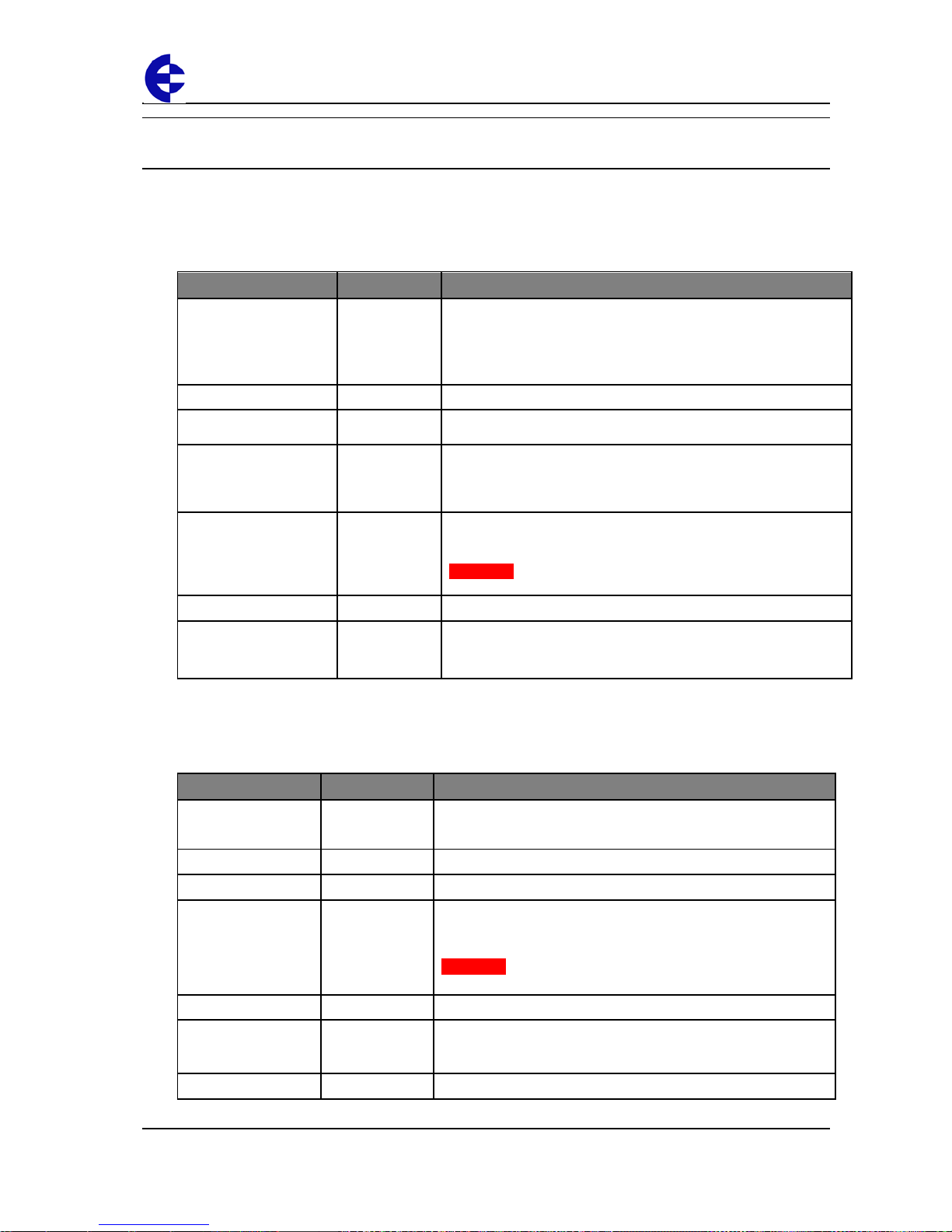
Unit specifications
This section details the specifications for each unit.
Transmitter unit
Input/output Number Additional information
Digital inputs
2
Dry-contact digital inputs slow-pulsed at 10Hz.
All inputs are suitable for voltage free contacts (e.g. mechanical
switches) or NPN transistor devices (e.g. electronic proximity
switches).
NOTE: PNP transistor device inputs are NOT suitable.
Status outputs
2 Separate System OK and Setpoint Status
Analog inputs
1
0-20mA differential input; 16-bit resolution, 0.1% accuracy, 10 ohm
input impedance.
Thermocouple inputs
1
J, K or T type thermocouple with on-board col d-junction
compensation.
Cold junction compensation accuracy ±1º over ambient temp
range: -40º to +70ºC.
Power supply
1
9-30 VDC 0.6 Amp CSA certified Class 2 power supply. For use in
Class 1 Div 2 explosive areas, the power supply must be approved
for Class 1 Div 2 use.
WARNING: Explosion hazard - do not disconnect while circuit is
live unless area is known to be non-hazardous.
Transmitter
1
5 mW or 500 mW DFSK Fixed Frequency Transmitter.
Frequency
868.525 MHz
869.875MHz
500 mW - 5km out of plant, 1km obstructed environment.
5 mW – 1km out of plant. 300m obstructed environment
Receiver unit
Input/output Number Additional information
Digital outputs
3 Voltage-free contacts rated at 250 VAC, 1A, 30VDC 1A
2 for digital inputs and 1 for setpoint.
Status outputs
2 Separate System OK and communication failure output.
Analog output
1 16-bit resolution, 0.1% accuracy, single-ended source output.
Power supply
1 9-30 VDC 0.25 Amp CSA certified Class 2 power supply. For use
in Class 1 Div 2 explosive areas, the power supply must be
approved for Class 1 Div 2 use.
WARNING: Explosion hazard - do not disconnect while circuit is
live unless area is known to be non-hazardous.
Radio receiver
1 High sensitivity DFSK Fixed Frequency receiver.
Frequency
868.525 MHz
869.875MHz
Actual frequency range depends on Paired Transmitter.
Sensitivity
-111 dBm At BER 8%.
Page 36
105U-L Wireless I/O Installation Manual
105U-L Wireless I/O Page 36 of 38
Version 1.8
Ancillary hardware reference information
This section contains reference information about additional hardware components you
may need for your unit.
RS232 serial cable
You can connect the unit to a PC using an RS-232 serial cable to:
Transfer configuration information;
Perform factory and field-testing.
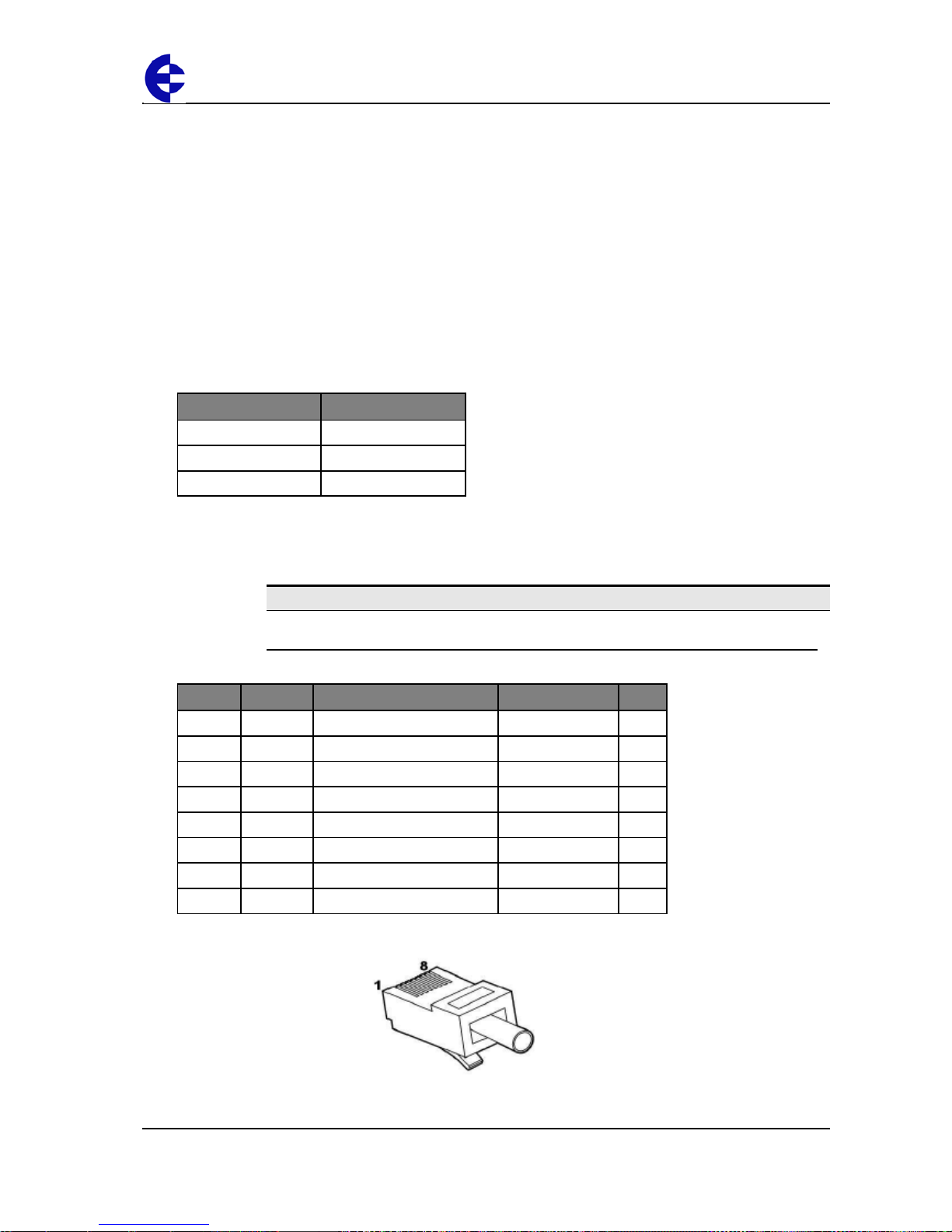
The serial port is an 8 pin RJ-45 plug that communicates using standard RS-232 signals:
Signal information Value
Baud rate
9600
Bits
8 bits with 1 stop bit
Parity
No parity
ELPRO supplies a green configuration cable wired to the following pin-out:
Note
The following pin-out information is for reference only.
RJ-45 Required Signal name Normal colour DB9
1
Ring Indicator Green / White 9
2
Data Carrier Detect Green 1
3
Y Data Terminal Ready Orange / White 4
4
Y Signal Common Blue 5
5
Y Receive Data (from Modem) Blue / White 2
6
Y Transmit Data (to Modem) Orange 3
7
Clear to Send Brown / White 8
8
Request to Send Brown 7
Page 37

105U-L Wireless I/O Installation Manual
105U-L Wireless I/O Page 37 of 38
Version 1.8
Index
2 wire transducer ..................................................... 26
4 wire transducer .................................................... 26
AC relays ................................................................. 23
active pulse device ................................................ See
active signal device ................................................. 22
analog input ............................................................. 25
analog output ........................................................... 30
antennas .................................................................. 16
compatible cables ............................................... 12
dipole .................................................................. 16
installing .............................................................. 14
polarization .......................................................... 18
supported antennas ............................................ 12
arcing ....................................................................... 23
bench testing ........................................................... 35
cable
loss ...................................................................... 13
cables
for antennas ........................................................ 12
supported cables ................................................. 12
CFD890EL ............................................................... 12
coaxial surge diverter .............................................. 15
configuration
default factory ...................................................... 34
user-defined customized ..................................... 34
configuring ............................................................... 34
connections
taping .................................................................. 15
current sink output ................................................... 27
current source output ............................................... 26
DC relays ................................................................. 23
DCS ......................................................................... 25
digital inputs............................................................. 22
DIN rail .................................................................... 33
dipole antennas ....................................................... 16
electronic proximity switches ................................... 22
explosive areas ........................................................ 20
floating input device ................................................. 30
flyback diodes .......................................................... 23
gain
net gain ............................................................... 13
horizontal polarization .............................................. 18
installing .................................................................. 33
instrument transducers ............................................ 25
interference.............................................................. 14
internal surge protection .......................................... 20
LEDs
receiver ............................................................... 11
transmitter ............................................................. 9
lightening rod ........................................................... 15
lightening strike ........................................................ 15
line of sight .............................................................. 14
linearization tables ................................................... 28
loop powered device ................................................ 30
maximum transmission distance .............................. 14
mechanical switches ................................................ 22
millivolt signal .......................................................... 28
net gain .................................................................... 13
obstructions ............................................................. 14
intermediate ........................................................ 14
over-voltage ............................................................. 25
passive transistor ..................................................... 29
pin-out...................................................................... 37
PLC ......................................................................... 25
polarization .............................................................. 18
polarized .................................................................. 18
power supply ........................................................... 20
installing .............................................................. 20
problems .................................................................. 35
pulse input ............................................................... 29
PVC tape ................................................................. 15
Radio Frequency Interference ................................. 25
receiver
components ......................................................... 10
front panel ........................................................... 11
LEDs ................................................................... 11
terminal connections ........................................... 10
relay outputs ............................................................ 23
reliable path ............................................................. 14
repeater ................................................................... 14
reverse voltage ........................................................ 25
RFI ........................................................................... 25
RJ-45 ....................................................................... 37
rotary switch .............................................................. 8
changing position .................................................. 8
setpoint levels ....................................................... 8
RS-232 .................................................................... 37
serial cable .............................................................. 37
setpoint
thermocouple ...................................................... 21
setpoint levels ................................
............................ 8
SG900-6 .................................................................. 12
SG900EL ................................................................. 12
shielding .................................................................. 15
signals ..................................................................... 34
single-ended input device ........................................ 31
SMA connector ........................................................ 15
solutions .................................................................. 35
Page 38

105U-L Wireless I/O Installation Manual
105U-L Wireless I/O Page 38 of 38
Version 1.8
specifications ........................................................... 36
status outputs .......................................................... 24
surge diverter........................................................... 15
surge protection ....................................................... 15
surge suppression ................................................... 15
switches
electronic proximity ............................................. 22
switches
mechanical .......................................................... 22
taping connections ................................................... 15
testing ...................................................................... 35
thermocouple ........................................................... 28
thermocouple setpoint ............................................. 21
transducers .............................................................. 25
transmitter
components ........................................................... 7
front panel ............................................................. 8
terminal connections ............................................. 7
UV-stabilized tape ................................................... 15
vertical polarization .................................................. 18
voltage free contact ................................................. 22
vulcanising tape ....................................................... 15
watchdog alarm ....................................................... 23
WH900..................................................................... 12
YU16/900................................................................. 12
YU6/900................................................................... 12
zener diode protection ............................................. 25
zero based signals ................................................... 25
 Loading...