

Page 1

For 105U-C and 105U-G products, refer to separate User Manuals
ELPRO Technologies Pty Ltd, 9/12 Billabong Street, Stafford Q 4053, Australia.
Tel: +61 7 33524533 Fax: +61 7 33524577 Email: [email protected]
Web: www.elprotech.com or www.elpro.com.au
User Manual
105U Radio Telemetry Module
105S Serial Telemetry Module
Page 2

105 Radio/Serial Telemetry Module User Manual
Page 2© January 2004
Thank you for your selection of the 105 m odule for your telemetry
needs. We trust it will give you many years of valuable service.
ATTENTION!
Incorrect termination of supply wires may
cause internal damage and will void warranty.
To ensure your 105 enjoys a long life,
double check ALL your connections with
the user’s manual
before turning the power on.
Page 3

Contents
man_105_2.9.doc Page 3
How to Use This Manual
To receive the maximum benefit from your 105 product, please read the Introduction,
Installation and Operation chapters of this manual thoroughly before putting the 105 to
work.
Chapter Four Configuration explains how to configure the modules using the Configuration
Software available.
Chapter Five Specifications details the features of the product and lists the standards to
which the product is approved.
Chapter Six Troubleshooting will help if your system has problems and Chapter Seven
specifies the Warranty and Service conditions.
The foldout sheet 105 Installation Guide is an installation drawing appropriate for most
applications.
Warning !
1. For 105U modules, a radio licence is not required in most countries, provided the
module is installed using the antenna and equipment configuration described in the
105 Installation Guide. Check with your local 105 distributor for further information
on regulations.
2. For 105U modules, operation is authorised by the radio frequency regulatory authority
in your country on a non-protection basis. Although all care is taken in the design of
these units, there is no responsibility taken for sources of external interference. The
105 intelligent communications protocol aims to correct communication errors due to
interference and to retransmit the required output conditions regularly. However some
delay in the operation of outputs may occur during periods of interference. Systems
should be designed to be tolerant of these delays.
3. To avoid the risk of electrocution, the antenna, antenna cable, serial cables and all
terminals of the 105 module should be electrically protected. To provide maximum
surge and lightning protection, the module should be connected to a suitable earth and
the antenna, antenna cable, serial cables and the module should be installed as
recommended in the Installation Guide.
4. To avoid accidents during maintenance or adjustment of remotely controlled
equipment, all equipment should be first disconnected from the 105 module during
these adjustments. Equipment should carry clear markings to indicate remote or
automatic operation. E.g. "This equipment is remotely controlled and may start
without warning. Isolate at the switchboard before attempting adjustments."
5. The 105 module is not suitable for use in explosive environments without additional
protection.
Caution!
For continued protection against risk of fire, replace the internal fuse only with the same t ype
and rating.
Page 4

105 Radio/Serial Telemetry Module User Manual
Page 4© January 2004
CONTENTS
CHAPTER ONE INTRODUCTION 6
1.1 G
ENERAL
6
CHAPTER TWO INSTALLATION 9
2.1 G
ENERAL
9
2.2 A
NTENNA INSTALLATION
(105U
UNITS ONLY
) 9
2.2.1 Dipole antenna. 10
2.2.3 Collinear antenna. 12
2.3 P
OWER SUPPLY
13
2.3.1 AC Supply 13
2.3.2 DC Supply 13
2.3.3 Solar Supply 14
2.3.4 Multiple Modules 15
2.3.5 24V Regulated Supply 15
2.4 I
NPUT
/ O
UTPUT
16
2.4.1 Digital Inputs (105-1, 105-2 and 105-4) 16
2.4.2 Digital Outputs (105-1) 16
2.4.3 Digital Outputs (105-2, 105-3 and 105-4) 17
2.4.4 Analogue Inputs (105-1 and 105-2) 17
2.4.5 Analogue Outputs (105-1 and 105-3) 18
2.4.6 Pulse Input (105-1) 20
2.4.7 Pulse Inputs (105-2 and 105-4) 20
2.4.8 Pulse Output (105-1) 21
2.4.9 Pulse Output (105-3 and 105-4) 21
2.4.10 RS232 Serial Port 22
2.4.11 RS485 Serial Port 22
2.4.12 Connecting 105S Modules to 105U Modules 23
CHAPTER THREE OPERATION 24
3.1 P
OWER-UP AND NORMAL OPERATION
24
3.1.1 Communications 24
3.1.2 Change of state conditions 26
3.1.3 Analogue Set-points 29
3.1.4 Start-up Poll 29
3.1.5 Communications Failure (CF) 29
3.1.6 Resetting Outputs 29
3.2 S
YSTEM DESIGN TIPS
30
3.2.1 System Dynamics 30
3.2.2 Radio Channel Capacity 30
3.2.3 Radio Path Reliability 30
3.2.4 Design for Failures 31
3.2.5 Indicating a Communications Problem 32
3.2.6 Testing and Commissioning 33
3.3 S
ECURITY CONSIDERATIONS
33
Page 5

Contents
man_105_2.9.doc Page 5
CHAPTER FOUR CONFIGURATION 34
4.1 I
NTRODUCTION
34
4.2 E
ASY CONFIGURATION USING DEFAULT SETTINGS
35
4.3 105 C
ONFIGURATION SOFTWARE
37
4.3.1 Hardware and Software Requirements 37
4.3.2 Programme Operation 38
4.3.3 Programming Configurations to Modules 49
4.3.4 Loading Configuration from a Module 50
4.3.5 Modifying and Archiving Configuration Files 50
4.3.6 Print Options 50
4.3.7 Security 50
4.3.8 Using 105S Modules 52
CHAPTER FIVE SPECIFICATIONS 55
CHAPTER SIX TROUBLESHOOTING 59
6.1 D
IAGNOSTICS CHART
59
6.2 S
ELF TEST FUNCTIONS
59
6.2.1 Input to Output Reflection (105-1 only) 59
6.2.2 Radio Testing using Tone Reversals 60
6.2.3 Diagnostics functions 60
105-3 Modules 64
6.2.4 Comms Logging 67
CHAPTER SEVEN WARRANTY & SERVICE 68
APPENDIX A SYSTEM EXAMPLE 69
APPENDIX B TERMINAL LAYOUTS 75
Page 6

105 Radio/Serial Telemetry Module User Manual
Page 6© January 2004
Chapter One INTRODUCTION
1.1 General
The 105 range of telemetry modules has been designed to provide standard “off-the-shelf”
telemetry functions, for an economical price. Telemetry is the transmission of signals over a
long distance via a medium such as radio or twisted-pair wire. Although the 105 is intended
to be simple in its application, it also provides many sophisticated features. This manual
should be read carefully to ensure that the modules are configured and installed to give
reliable performance.
The unit can monitor and control the following types of signals:
Digital on/off signals
Example outputs - motor run, siren on
Example inputs - motor fault, tank overflow, intruder alarm
Analogue continuously variable signals (0-20mA)
Example outputs - tank level indication, required motor speed
Example inputs - measured tank level, actual motor speed
Pulse frequency signals
Examples - electricity metering, fluid flow
Internal Status signals
Examples - analogue battery voltage, power status, solar panel status and low
battery status.
The unit will monitor the input signals and transmit the signal information by radio or RS485
twisted pair to another 105 module. At the remote unit, the signals will be reproduced as
digital, analogue or pulse output signals. The 105 also provides analogue set points, so that a
digital output may be configured to turn on and off depending on the value of an analogue
input. The pulse I/O transmits an accumulated value and the pulses are reliably recreated at
the remote unit regardless of ‘missed’ transmissions. The actual pulse rate is also calculated
and is available as a remote analogue output.
This manual covers the 105U and 105S modules. We have provided a summary on all
products available in the 105 telemetry range, below.
• 105U-1, 105U-2, 105U-3 and 105U-4 modules have UHF radio and serial
communications. The modules differ only in their input/output (I/O) design, and are
compatible, i.e. they can be used to communicate signals to each other in the same
network.
• 105S-1, 105S-2, 105S-3 and 105S-4 modules have only serial communications. All other
specifications are as per the 105U-1, 2, 3 & 4 modules. The 105S modules are compatible
with 105U modules.
Page 7
Chapter One Introduction
man_105_2.9.doc Page 7
• The 105U-C and 105U-G modules provide an interface between host devices such as
PLC’s or SCADA computers, and a radio telemetry system comprising 105U and 505U
radio telemetry modules. The 105U-C and -G allows 105U/505U modules to act as
remote wireless I/O for the host devices. For more information, refer to the relevant User
Manual.
Product naming convention:
1 0 5 a – x where a is:
U = UHF radio + RS232/RS485 serial S = RS232/RS485 serial only
and x is:
1 = Input / Output module 2 = Input module ( includes one output) 3 = Output module
4 = Input / Output module C= Interface module
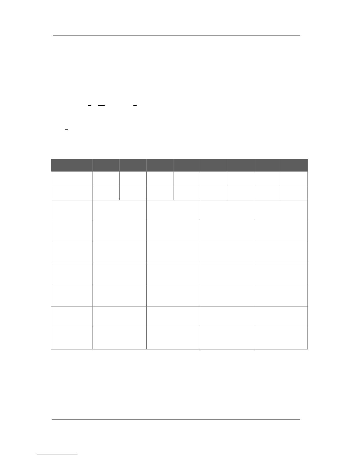
105U-1 105S-1 105U-2 105S-2 105U-3 105S-3 105U-4 105S-4
Radio
!!!!
Serial
!!!!!!!!
Digital
Inputs (DI)
4 4 4 to 16
Digital
Outputs (DO)
4 (relay) 1 (FET) 8 (FET) 4 to 16 (FET)
Analogue
Inputs (AI)
2 (4-20mA) 6 (0-20mA)
Analogue
Outputs (AO)
2 (4-20mA) 8 (0-20mA)
Pulse Inputs
(PI)
1 (100Hz) 4 (1x1KHz,
3x100Hz)
4 (1x1KHz,
3x100Hz)
Pulse
Outputs (PO)
1 (100Hz) 4 (100 Hz) 4 (100 Hz)
Comments
PI is DI 1. PO is
separate to DO.
PI’s are the same
as DI’s.
PO’s are the same
as DO’s .
PI/ PO’s are the
same as DI/ DO’s.
Note regarding 105-4 modules. The 105-4 has a total of 20 digital I/O. Four are fixed
inputs (also PI’s) and four are fixed outputs (also PO’s). The other 12 are selectable
individually as DI or DO. The I/O range can vary from 16DI + 4DO to 4DI + 16DO or any
combination in between.
All modules include power supply, microprocessor controller, input/output circuits,
RS485/232 serial port, and a UHF radio transceiver - no external electronics are required.
Page 8

105 Radio/Serial Telemetry Module User Manual
Page 8© January 2004
The 105U version has both radio and serial port communications. The 105S version does not
have a radio and has only serial communications. The 105U radio frequency has been selected
to meet the requirements of unlicensed operation for remote monitoring and control of
equipment. That is, a radio licence is not required for the 105 modules in many countries.
See Chapter Five Specifications for details.
Input signals connected to a 105 module are transmitted to another 105 module and appear as
output signals. These input signals may also be configured to appear as “inverted” signals on
the output. A transmission occurs whenever a "change-of-state" occurs on an input signal. A
"change-of-state" of a digital or digital internal input is a change from "off" to "on" or viceversa. A "change-of-state" for an analogue input, internal analogue input or pulse input rate is
a change in value of the signal of 3% (configurable from 0.8 to 50 %).
In addition to change-of-state messages, update messages are automatically transmitted on a
regular basis. The time period may be configured by the user for each input. This update
ensures the integrity of the system.
Pulse inputs are accumulated as a pulse count and the accumulated pulse count is transmitted
regularly according to the configured update time.
The 105 modules transmit the input/output data as a data frame using radio or serial RS485 as
the communications medium. The data frame includes the "address" of the transmitting 105
module and the receiving 105 module, so that each transmitted message is acted on only by
the correct receiving unit. Each transmitted message also includes error checking to ensure
that no corruption of the data frame has occurred due to noise or interference. The 105
module with the correct receiving "address" will acknowledge the message with a return
transmission. If the original module does not receive a correct acknowledgement to a
transmission, it will retry up to five times before setting the communications fail status of that
path. In critical paths, this status can be reflected on an output on the module for alert
purposes. The module will continue to try to establish communications and retry, if required,
each time an update or change-of-state occurs.
A 105 telemetry system may be a complex network or a simple pair of modules. An easy-touse configuration procedure allows the user to specify any output destination for each input.
The maximum number of modules in one system is 95 modules communicating by radio.
Each of these modules may have up to 31 other modules connected by RS485 twisted pair.
Modules may communicate by radio only, by RS485 only or by both RS485 and radio. Any
input signal at any module may be configured to appear at any output on any module in the
entire system.
Systems with a 105U-C or 105U-G module and host device can have more than 95 radio
modules.
Modules can be used as repeaters to re-transmit messages on to the destination module.
Repeaters can repeat messages on the radio channel, or from the radio channel to the serial
channel (and serial to radio). Up to five repeater addresses may be configured for each inputto-output link.
The units may be configured by using a PC connected to the RS232 port. The default
configuration is defined in Section 4.2 Easy Configuration Using Default Settings, and
software configuration is defined in Section 4.2 105 Configuration Software.
Page 9

Chapter Two Installation
man_105_2.9.doc Page 9
Chapter Two INSTALLATION
2.1 General
The 105 module is housed in a rugged aluminium case, suitable for DIN-rail mounting. Terminals
are suitable for cables up to 2.5 sqmm in size.
Normal 110/220/240V mains supply should not be connected to any input terminal of the 105
module. Refer to Section 2.3 Power Supply.
Before installing a new system, it is preferable to bench test the complete system. Configuration
problems are easier to recognise when the system units are adjacent. Following installation, the
most common problem is poor communications on the radio channel or the serial channel. For
radio modules, problems are caused by incorrectly installed antennas, or radio interference on the
same channel, or the radio path being inadequate. If the radio path is a problem (i.e. path too long,
or obstructions in the way), then higher performance antennas or a higher mounting point for the
antenna may fix the problem. Alternately, use an intermediate 105 module as a repeater.
For serial modules, poorly installed serial cable, or interference on the serial cable is a common
problem.
The foldout sheet 105 Installation Guide provides an installation drawing appropriate to most
applications. Refer to Appendix B of this manual for terminal layout drawings of the modules.
Each 105 module should be effectively earthed via a "GND" terminal on the 105 module - this is to
ensure that the surge protection circuits inside the 105 module are effective.
2.2 Antenna Installation
(105U units only)
The 105 module will operate reliably over large distances. The distance which may be reliably
achieved will vary with each application - depending on the type and location of antennas, the
degree of radio interference, and obstructions (such as hills or trees) to the radio path. Please refer
to your distributor for the expected maximum distance to comply with local radio regulations.
Where it is not possible to achieve reliable communications between two 105 modules, then a third
105 module may be used to receive the message and re-transmit it. This module is referred to as a
repeater. This module may also have input/output (I/O) signals connected to it and form part of the
I/O network - refer to Chapter 4 Configuration of this manual.
An antenna must be connected to each 105 module using the coaxial female connector which
protrudes though one of the end plates.
To achieve the maximum transmission distance, the antennas should be raised above intermediate
obstructions so the radio path is true “line of sight”. Because of the curvature of the earth, the
antennas will need to be elevated at least 5 metres above ground for paths greater than 5 km (3
miles). For short distances, the modules will operate reliably with some obstruction of the radio
path. Obstructions which are close to either antenna will have more of a blocking affect than
obstructions in the middle of the radio path. For example, a group of trees around the antenna is a
Page 10

105 Radio/Serial Telemetry Module User Manual
Page 10 © January 2004
larger obstruction than a group of trees 100 metres from the antenna.
An antenna should be connected to the module via 50 ohm coaxial cable (eg RG58 or RG213)
terminated with a male coaxial connector. The higher the antenna is mounted, the greater the
transmission range will be, however as the length of coaxial cable increases so do cable losses. For
use on unlicensed frequency channels, there are several types of antennas suitable for use. It is
important antenna are chosen carefully to avoid contravening the maximum power limit on the
unlicensed channel - normally the net gain of the antenna/cable configuration should be no more
than 2dB.
The net gain of an antenna/cable configuration is the gain of the antenna (in dBi) less the loss in the
coaxial cable (in dB).
The gains and losses of typical antennas are
Antenna Gain (dB)
Dipole with integral 3m cable 0
Dipole without cable 2
5dBi Collinear(3dBd) 5
8dBi Collinear (6dBd) 8
3 element Yagi 5
6 element Yagi 10
Cable type Loss (dB per 10 m)
400-500MHz 869MHz
RG58 -3 -5
RG213 -1.5 -2.5
Cellfoil -1.5 -3
The net gain of the antenna/cable configuration is determined by adding the antenna gain and the
cable loss. For example, a 3 element Yagi with 15 metres of RG58 has a net gain of 0.5dB (5dB –
4.5dB) at 450MHz.
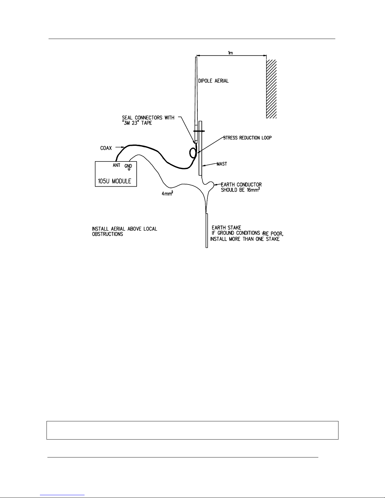
Connections between the antenna and coaxial cable should be carefully taped to prevent ingress of
moisture. Moisture ingress in the coaxial cable is a common cause for problems with radio systems,
as it greatly increases the radio losses. We recommend that the connection be taped, firstly with a
layer of PVC Tape, then with a vulcanising tape such as “3M 23 tape”, and finally with another
layer of PVC UV Stabilised insulating tape. The first layer of tape allows the joint to be easily
inspected when trouble shooting as the vulcanising seal can be easily removed.
Where antennas are mounted on elevated masts, the masts should be effectively earthed to avoid
lightning surges. The 220MHz and 400 – 500MHz radios are fitted with surge protection, however
the 868MHz radio does not. For high lightning risk areas, additional surge suppression devices are
recommended. If the antenna is not already shielded from lightning strike by an adjacent earthed
structure, a lightning rod may be installed above the antenna to provide shielding.
2.2.1 Dipole antenna.
A unity gain dipole is the normal antenna for use on unlicensed channels. As it does not provide
Page 11
Chapter Two Installation
man_105_2.9.doc Page 11
any gain, then the power transmitted from the antenna will be the same as the power out of the
module, and hence will not exceed the permitted power of the unlicensed channel.
Dipole antennas should be mounted vertically, at least 1 metre away from a wall or mast for
maximum performance.
2.2.2 Yagi antenna.
Yagi antennas are directional. That is, they have positive gain to the front of the antenna, but
negative gain in other directions. This may be used to compensate for coaxial cable loss for
installations with marginal radio path.
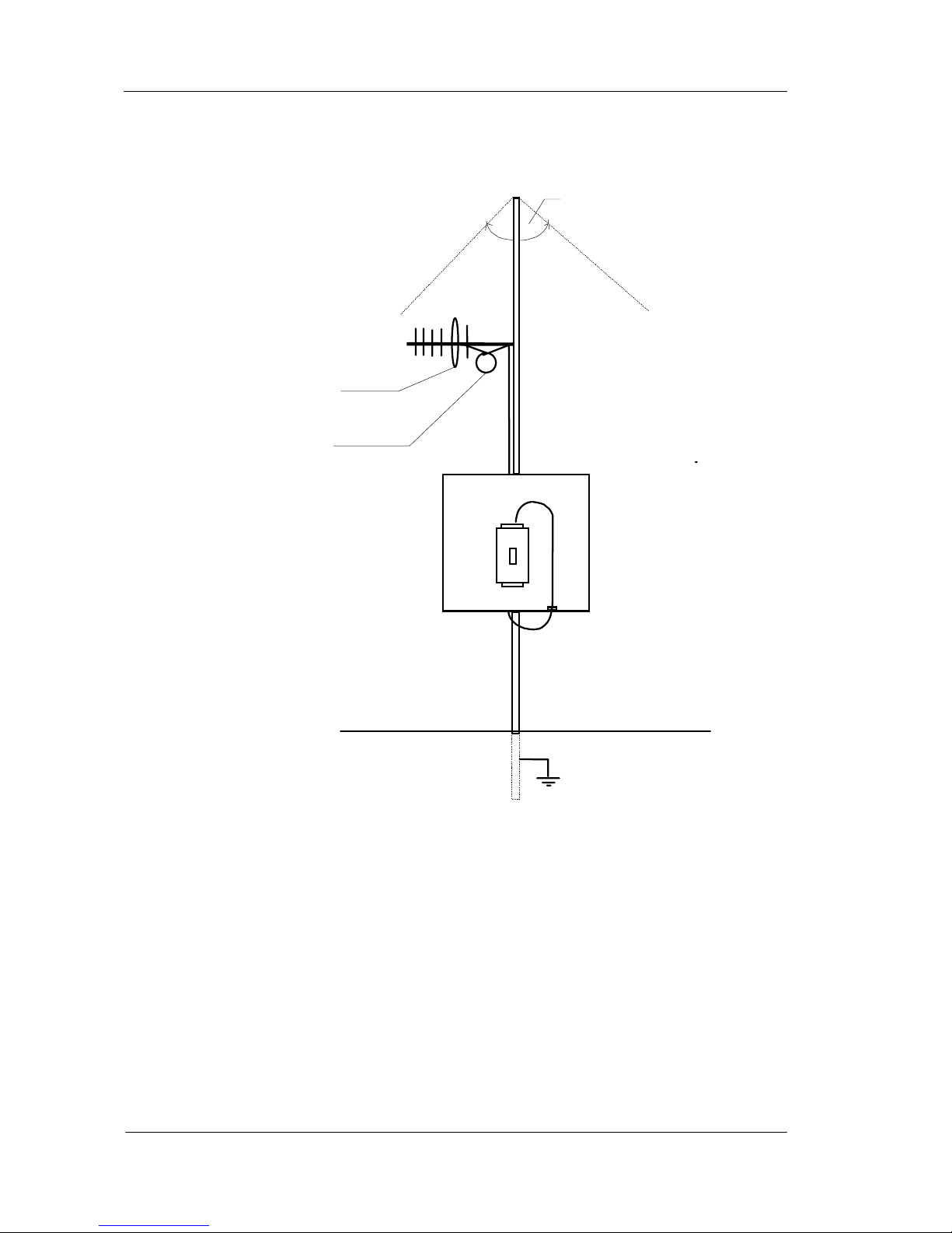
Yagi antennas should be installed with the central beam horizontal and must be pointed exactly in
the direction of transmission to benefit from the gain of the antenna.
The Yagi antennas may be installed with the elements in a vertical plane (vertically polarised) or in
a horizontal plane (horizontally polarised). For a two station installation, with both modules using
Yagi antennas, horizontal polarisation is recommended. If there are more than two stations
transmitting to a common station, then the Yagi antennas should have vertical polarisation, and the
common (or “central” station should have a dipole or collinear (non-directional) antenna.
Note that Yagi antennas normally have a drain hole on the folded element - the drain hole should
be located on the bottom of the installed antenna.
Page 12
105 Radio/Serial Telemetry Module User Manual
Page 12 © January 2004
2.2.3 Collinear antenna.
A collinear antenna may be used in the same way as a 3 element Yagi to compensate for the losses
in long lengths of coaxial cable. This type of antenna is generally used at a central site with more
than one remote site or at a repeater site. The collinear antenna looks similar to the dipole, ex cept
that it is longer.
105U
An tenna installed
with drain holes
down
Coax feed looped
at connection
90
o
Page 13
Chapter Two Installation
man_105_2.9.doc Page 13
2.3 Power Supply
The 105 power supply is a switch-mode design which will accept either AC or DC supply. The 105
module may also be powered from a solar panel without an external solar regulator.
The 105 module accepts supply voltages in the following ranges :
12 - 24 volts AC RMS or 15 - 30 volts DC at the “supply” terminals, or
10.8 -15 volts DC at the “battery” terminals.
The power supply should have a minimum capacity of 9 Watts.
Note: Connect module to the same ground/earth point as the antenna mounting to avoid differences
in earth potential during voltage surges. The modules needs an earth connection for the internal
surge protection to be effective.
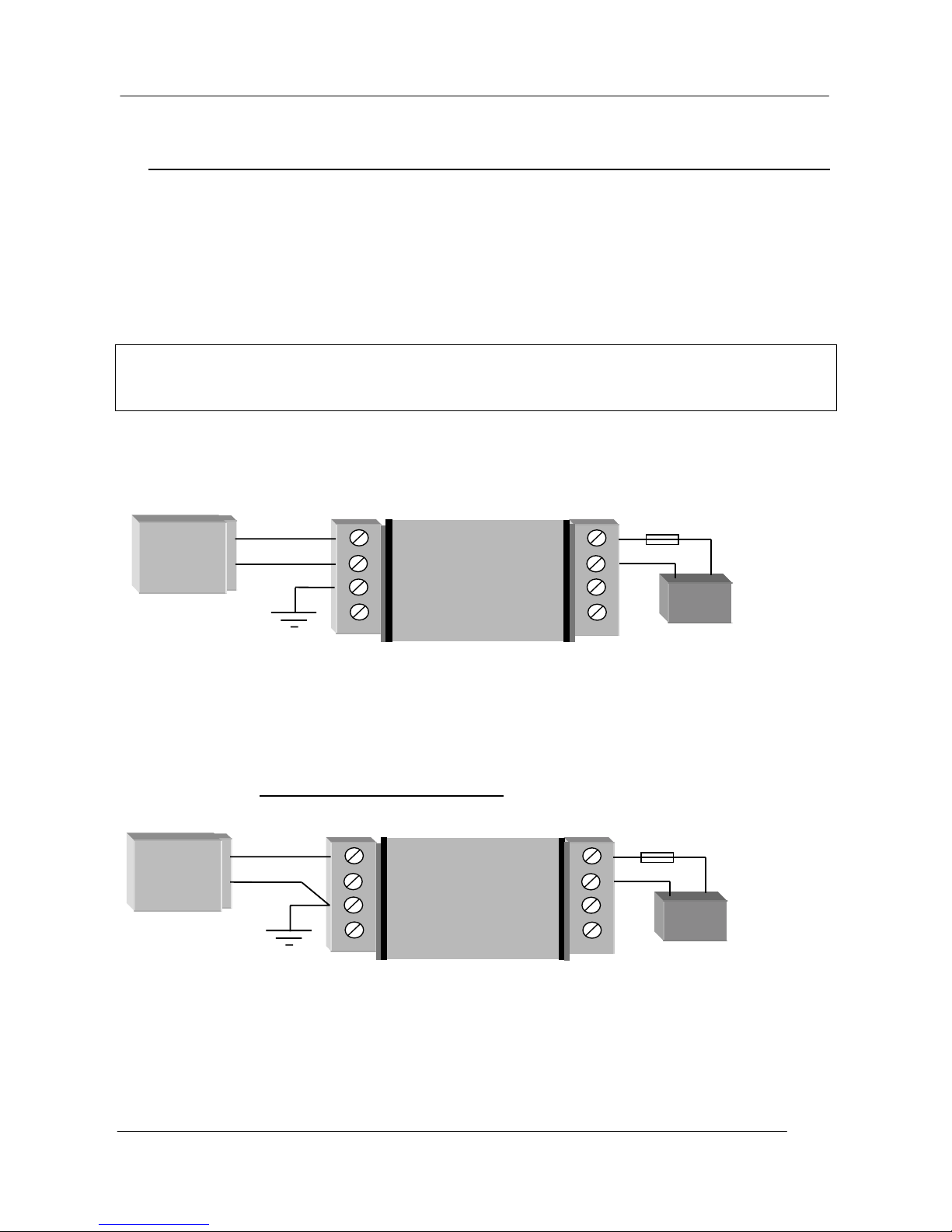
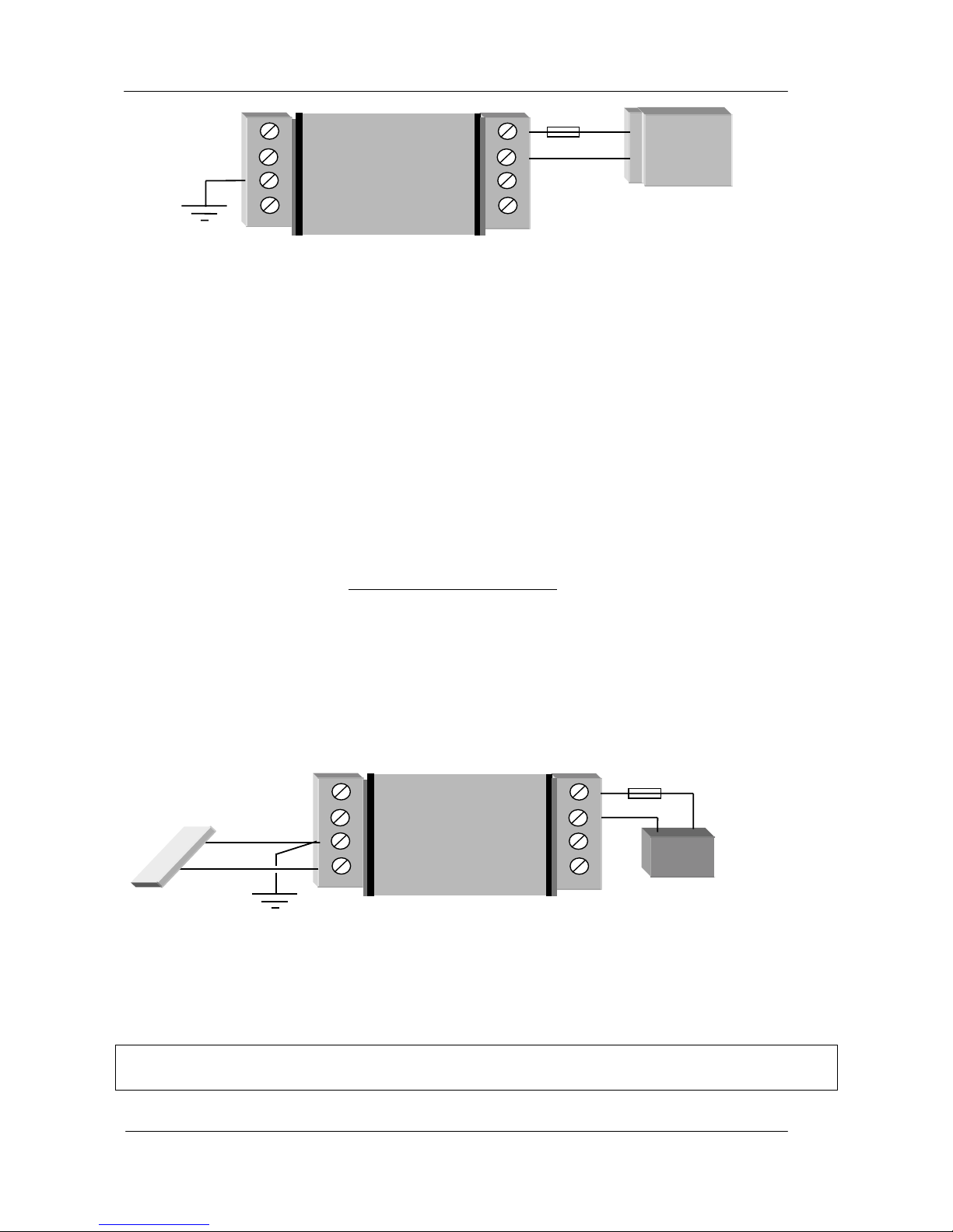
2.3.1 AC Supply
The AC supply is connected to the "SUP1" and "SUP2" terminals as shown below.
The AC supply should be "floating" relative to earth. AC transformers with grounded/earthed
secondary windings should not be used.
2.3.2 DC Supply
For DC supplies, the positive lead is connected to "SUP1" and the negative to "GND". The positive
side of the supply must not be connected to earth. The DC supply may be a floating supply or
negatively grounded.
The 105 module may also be powered from an external 11.5 - 15 VDC battery supply without the
need for a "normal" supply connected to "SUP1". This external battery supply is connected to
"BAT+" and "GND" terminals. The positive lead of the external supply should be protected by a 2A
fuse.
Optional Battery
Fuse 2A
_
+
SUP1
SUP2
GND
SOL
Power
Supply
DC Out
BAT+
GND
-
+
105U
15 – 30 VDC
>17V if battery
is used
SUP1
SUP2
GND
SOL
12 – 24 VAC
Power
Supply
AC Out
BAT+
GND
-
+
105U
Optional Battery
Fuse 2A
Page 14
105 Radio/Serial Telemetry Module User Manual
Page 14 © January 2004
Upon failure of the normal supply, the 105 module may continue to operate for several hours from a
backup battery. The 105 module includes battery charging circuits for charging up to a 12 AHr
sealed lead acid battery. The battery is connected to the "BAT+" (positive) and "GND" (negative)
terminals. The positive lead from the battery should be protected with a 2A fuse, installed as near to
the battery terminal as possible. On return of main supply, the unit will switch back to mains
operation, and recharge the battery. To provide adequate current to recharge the backup battery, an
AC supply of 15V minimum or a DC supply of 17V minimum must be used. Typically, a 6 AHr
battery will supply the 105 for 1 - 3 days, depending on I/O loads.
2.3.3 Solar Supply
The 105 power supply also includes a 12 V solar regulator for connecting 12V solar panels of up to
30W, and solar batteries of up to 100AHr. An 18W solar panel is sufficient for most solar
applications. The size of the solar battery required depends on the I/O used. Batteries are sized for
a number of sunless days with 50% battery capacity remaining as follows:
No. of sunless days = Battery capacity (AHr) x 0.5
Module load (A) x 1.2 x 24
The Module load depends on the I/O connected and can be calculated as follows:
Module Load(A) = 0.07 + (0.01 x No. of DI’s) + (0.025 x No. of DO’s)
+ (2 x Analogue loop load).
The analogue loop load is the total signal current for the AI’s and AO’s which are powered from the
internal 24V supply. Externally powered loops are not included in this.
The solar panel is connected to the "SOL" (positive) and "GND" (negative) terminals and the battery
connected to the "BAT+" (positive) and "GND" (negative) terminals. Solar panels must be installed
and connected as per the panel manufacturer's instructions. The positive lead of the battery should
be protected by a 2A fuse installed as near as possible to the battery terminal.
Where a panel larger than 30W is required, an external solar regulator should be used.
Note: The unit must not be powered from a solar panel w ithout a battery. For maintenance,
disconnect the solar panel first before disconnecting the battery.
_
+
SUP1
SUP2
GND
SOL
Power
Supply
DC Out
BAT+
GND
105U
11.5 – 15 VDC
Fuse 2A
_
+
SUP1
SUP2
GND
SOL
BAT+
GND
-
+
105U
Solar Battery
Fuse 2A
Solar Panel
Page 15

Chapter Two Installation
man_105_2.9.doc Page 15
2.3.4 Multiple Modules
Where more than one module is installed at the one location, a shared power supply and battery
may be used, provided the total load does not exceed the power supply.
The internal power supply of the 105 module can supply a maximum 12V load of 700mA. In order
to achieve this, the input power supply must be above 15VAC or 17VDC. Using these figures, it
can be determined whether there is enough supply for more than one module - allow 100mA for
recharging a battery.
For example, assume there is a 105U-01 module and a 105S-01 module at the same location. The
total I/O at the location is 3 analogue inputs, 6 digital inputs and 4 digital outputs. The total load
will be :-
TYPE OF LOAD LOAD mA
105U-01 quiescent 70
105S-01 quiescent 45
6 DI @ 10 mA 60
3 AI @ 20mA x 2 120
4 DO @ 25mA 100
Battery charging 100
TOTAL 495
So both modules could be powered from one power supply and one battery, provided the external
supply voltage is more than 15VAC or 17VDC.
2.3.5 24V Regulated Supply
Each 105 module provides a 24V DC regulated supply for analogue loop power, except for 105-4.
The supply is rated at 150mA, and should only be used for powering analogue loops.
Page 16
105 Radio/Serial Telemetry Module User Manual
Page 16 © January 2004
2.4 Input / Output
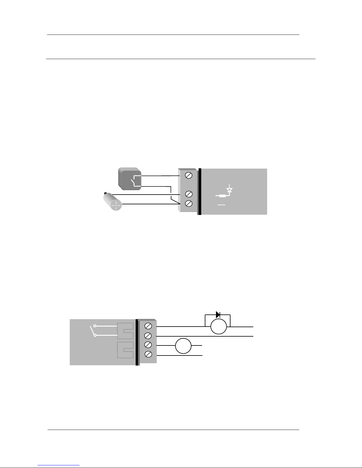
2.4.1 Digital Inputs (105-1, 105-2 and 105-4)
The 105-1 and 105-2 modules each provide four digital inputs with 5000 volt opto-isolation, and the
105-4 provides 4 – 16 inputs with 3000 volt surge protection. All inputs are suitable for voltage
free contacts (such as mechanical switches) or NPN transistor devices (such as electronic proximity
switches). PNP transistor devices are not suitable. Contact wetting current of approximately 5mA
is provided to maintain reliable operation of driving relays.
Each digital input is connected between the appropriate "DI" terminal and common "COM". Each
digital input circuit includes a LED indicator which is lit when the digital input is active, that is,
when the input circuit is closed. Provided the resistance of the switching device is less than 200
ohms, the device will be able to activate the digital input.
For pulse inputs, refer to Section 2.4.6.
2.4.2 Digital Outputs (105-1)
The 105-1 module provides four normally open voltage-free relay contacts, rated at AC3 50V/2A, ;
DC - 30V/2A, 20V/5A. These outputs may be used to directly control low-powered equipment, or
to power larger relays for higher powered equipment. When driving inductive loads such as AC
relays, good installation should include capacitors (e.g. 10nf 250V) across the external circuit to
prevent arcing across the relay contacts. For DC inductive loads, flyback diodes should be used
across DC relays.
Digital outputs may be configured to individually turn off if no command message is received to
that output for a certain period. This feature provides an intelligent watch dog for each output, so
that a communications failure at a transmitting site causes the output to revert to a known state. See
section 4.4 Changing User Options for further details.
_
+
DO 1
DO 2
105U
Max 50VAC
5A
AC
Load
DC
Load
Max 30VDC
2A
+
_
DI 1
DI 4
COM
105U
Voltage-free
contact in
p
ut
Transistor
in
p
ut
V
+
V
-
Page 17
Chapter Two Installation
man_105_2.9.doc Page 17
The output circuit is connected to the appropriate pair of "DO" terminals. Each digital output
circuit includes a LED indicator which is lit when the digital output is active.
2.4.3 Digital Outputs (105-2, 105-3 and 105-4)
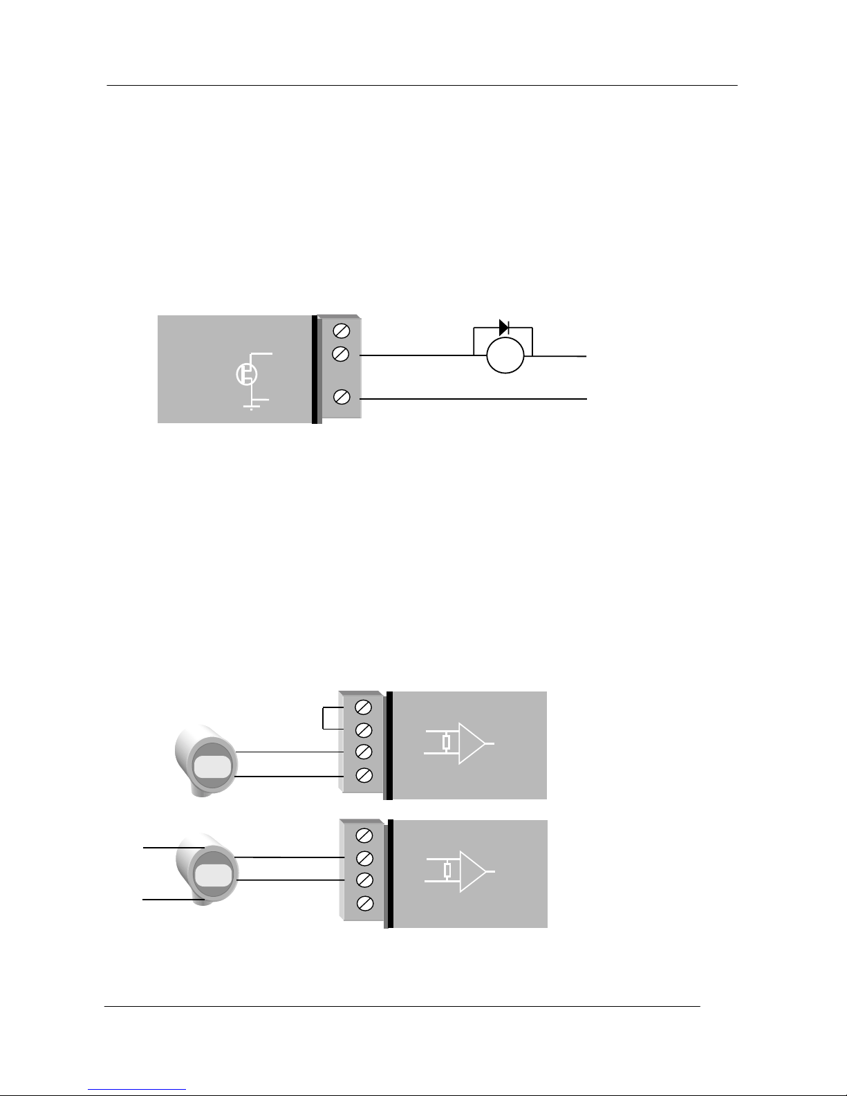
The digital outputs on the 105-2, 105-3 and 105-4 modules are transistor switched DC signals,
FET output to common rated at 30VDC 500 mA. The 105-2 provides one digital output; the 105-3
provides eight digital outputs and the 105-4 provides 4 – 16 outputs. The first four DO’s on the
105-3 and 105-4 modules are also the pulse outputs - that is, the first four DO's can be either
digital outputs or pulse outputs. The function of each of these outputs may be configured
individually. For a description of pulse outputs, refer to Section 2.4.7.
Digital outputs may be configured to individually turn off if no command message is received to
that output for a certain period. This feature provides an intelligent watch dog for each output, so
that a communications failure at a transmitting site causes the output to revert to a known state. See
Chapter 4 Configuration for further details.
The output circuit is connected to the appropriate pair of "DO" terminals. Each digital output circuit
includes a LED indicator which is lit when the digital output is active.
2.4.4 Analogue Inputs (105-1 and 105-2)
The 105-1 module provides two 4 - 20 mA DC analogue inputs for connecting to instrument
transducers such as level, moisture, pressure transducers, etc. The 105-2 module provides six 0 20 mA DC analogue inputs. Note that the inputs on the 105-2 module will measure down to 0mA,
so they can also be used for zero based signals such as 0 - 10 mA.
Each analogue input has a positive and negative terminal, and may be placed at any point in the
current loop, as long as neither input rises above the 24 volt supply level. Each input has a loop
4-20mA
+
_
+24V
+AI
- AI
COM
105U
2-wire
Input
+
_
+24V
+AI
- AI
COM
105U
4-wire
Input
External
Power
Note:
AI must be within
27V of COM. If
terminal voltages
exceed this, a
loop isolator must
be used.
_
+
DO 1
DO 2
COM
105U
DC
Load
Max 30VDC
0.5A
Page 18
105 Radio/Serial Telemetry Module User Manual
Page 18 © January 2004
resistance of less than 250 ohms and zener diode protection is provided against over-voltage and
reverse voltage, however additional protection may be required in high voltage or noisy
environments or for very long wiring runs.
A 24VDC loop supply is available on the 105 module for powering the analogue transducer loops.
In this case, the analogue loop should be connected between a "AI 1-" terminal and "COM" ( for
the first analogue input) or "AI 2-" ( for the second analogue input), and so on for other inputs. The
positive terminal ("AI 1+" or "AI 2+", etc) should be connected to "+24V".
Externally powered loops may be connected by connecting the input between "AI 1+" and “AI 1-”
for analogue input 1 or "AI 2+" and “AI 2-” for analogue input 2, and so on for other inputs.
Common mode voltage may be -0.5V to 27V.
Shielded cable is recommended for analogue I/O loops to minimise induced noise and Radio
Frequency Interference (RFI). The shield of the cable should be connected to earth at one of the
cable only. The use of shielded wiring inside an enclosure containing a 105 module is also
recommended.
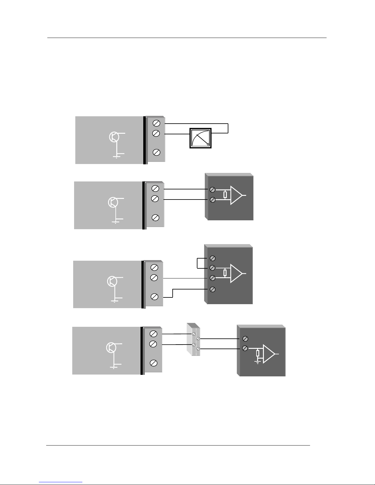
To connect an AI on the 105U to an analogue signal from a PLC or DCS output, check the internal
circuit of the output carefully as different devices use different ways to create an analogue signal.
The following diagram shows two ways of connecting.
2.4.5 Analogue Outputs (105-1 and 105-3)
The 105-1 module provides two 4 - 20 mA DC analogue outputs for connecting to instrument
indicators for the display of remote analogue measurements. The 105-3 module provides eight 0 20 mA DC analogue outputs. Each analogue output is a "sink" to common.
A 24VDC supply is available on the 105 module for powering the analogue output loop (max
external loop resistance 1000 ohms). In this case, the analogue loop is connected between a "+24V"
terminal and "AO 1" ( for the first analogue output) or "AO 2" (for the second analogue output),
and so on for the other output signals.
If connecting to an external device such as an electronic indicator, recorder or PLC / DCS input,
AO
PLC
_
+24V
+AI
- AI
COM
105U
+24V
+AI
- AI
COM
105U
Current
source
output
Note:
1. AI must be within
27V of COM. If
terminal voltages
exceed this, a loop
isolator must be
used.
2. COM on the
105U is connected
to ground/earth. If
the COM of the
PLC cannot be
grounded, then a
loop isolator must
be used.
+
+
V
-
V
AO
COM
PLC
Current
sink
output
Page 19
Chapter Two Installation
man_105_2.9.doc Page 19
the loop can be powered be either the 105U or the device. Externally powered loops to 27 VDC
may be connected by connecting the output between the "AO” terminal (positive) and the
"COM" terminal (negative). Zener protection of analogue outputs provides protection against short
periods of over-voltage but longer periods may result in module damage.
Note that the 105 common is connected internally to ground and no other point in the analogue loop
should be grounded. If the external device has single-ended grounded inputs, then a signal isolator
must be used.
Analogue outputs may also be configured to individually turn off (0 mA) if no command message is
received to that output for a certain period. . See Chapter 4 Configuration for further details.
_
+
+24V
AO 1
COM
105U
DEVICE
_
Note:
COM on 105U is
connected to
ground/earth. If
the external power
supply cannot be
grounded, a loop
isolator must be
used.
+
Connecting to a floating input device, powered from the 105U
+24V
AO 1
COM
105U
+V
-
V
DEVICE
+
+24V
AO 1
COM
105U
_
Connecting to an externally powered floating-input device
+V
DEVICE
AI
+24V
AO 1
COM
105U
Signal
Isolator
Connecting to a grounded input device via a signal isolator
Page 20
105 Radio/Serial Telemetry Module User Manual
Page 20 © January 2004
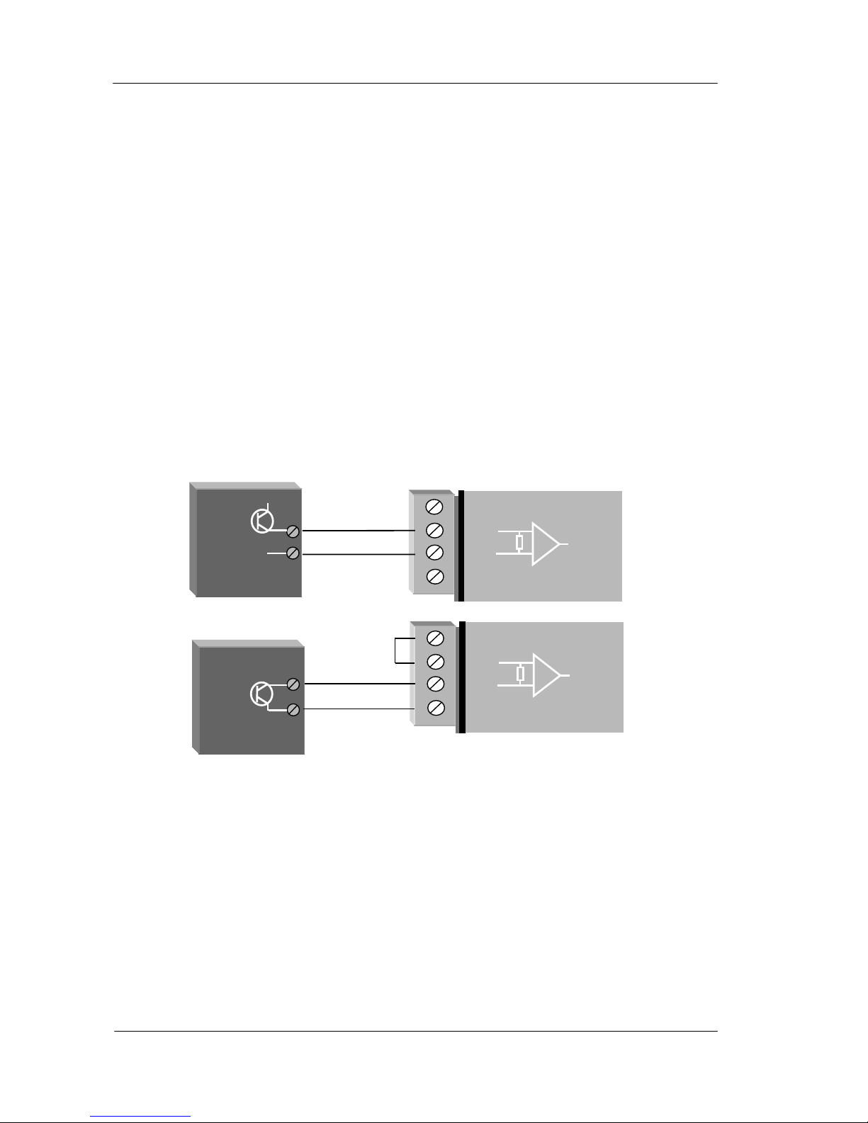
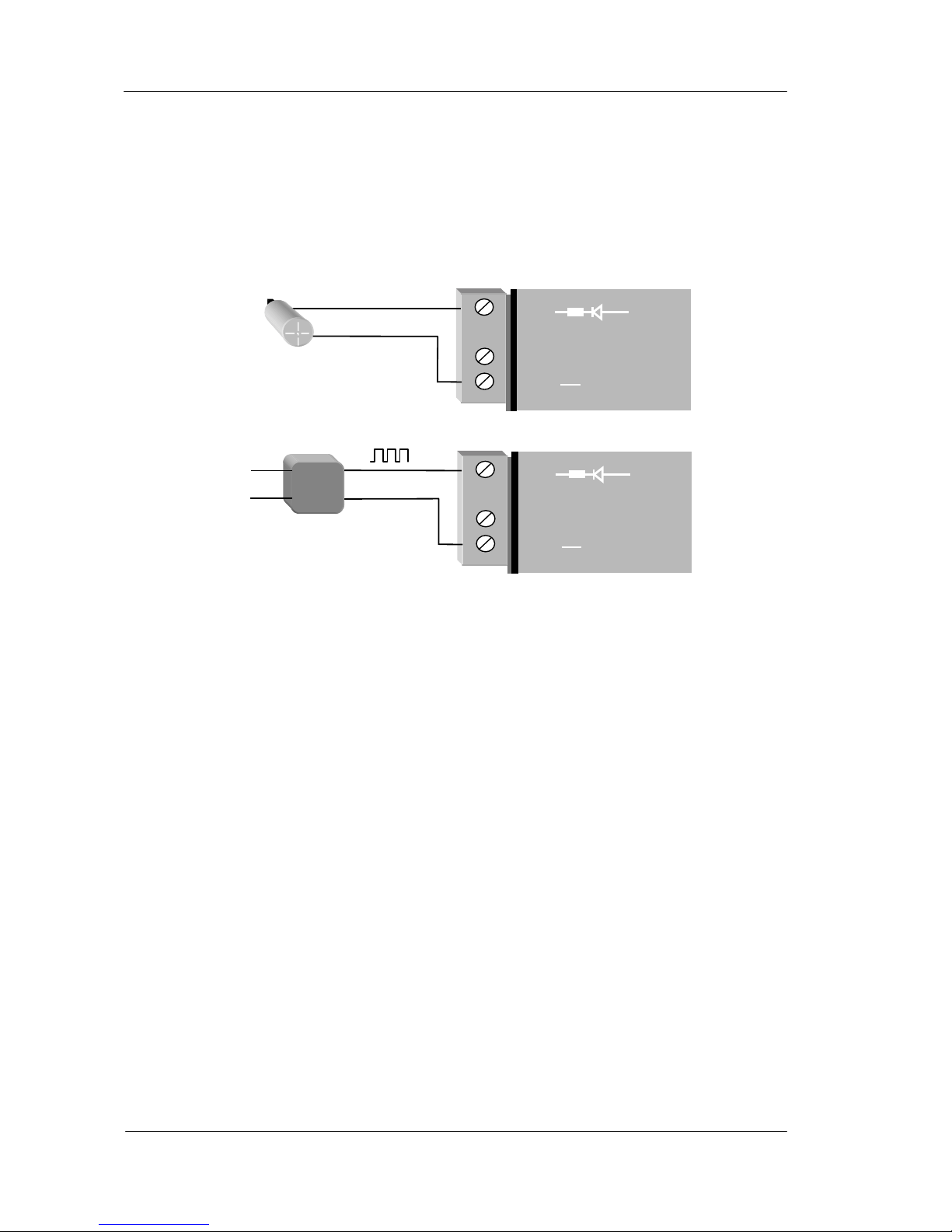
2.4.6 Pulse Input (105-1)
For the 105-1 module, digital input 1 may be configured as a pulse input (max rate 100 Hz, min. off
time 5 ms). In this mode, both the pulse rate and the pulse count are available for mapping to a
remote output. The pulse rate may appear at any analogue output on the remote unit, while the
pulse count can appear at a Pulse Output on another 105-1 or Digital Output on a 105-3 unit. The
pulse input should be connected in the same way as a digital input.
Active pulse signals can be connected directly provided the peak voltage is between 3.5–13V and
the low voltage is less than 1.5V. Note that the 105U will ground the negative of the pulse signal.
If the voltages are not compatible, use a solid state relay to isolate the two devices.
2.4.7 Pulse Inputs (105-2 and 105-4)
For the 105-2 and 105-4 modules, the four digital inputs (DI 1-4) may be configured as pulse
inputs. The first digital/pulse input DI 1 has a maximum rate of 1000 Hz (min. off time 0.5 ms),
while DI 2-4 have a maximum rate of 100 Hz (min. off time 5 ms). When using DI 1 at high pulse
rates (more than 100 Hz), a divide by 10 function may be configured to reduce the pulse count at
the output, as Pulse Outputs have a maximum rate of 100 Hz.
For each pulse input, both the pulse rate and the pulse count are available for mapping to a remote
output. The pulse rate may appear at any analogue output on the remote unit, while the pulse count
can appear at a Pulse Output. The default update time for pulse counts is 1 minute. This can be
changed by changing the update time configuration - refer Chapter 4 Configuration for further
details. The pulse count is a 16 bit value - “roll over” of the count when it exceeds the maximum
value is automatically handled by the 105 modules.
+
_
DI 1
COM
105U
Passive
transistor
device
+
_
+
_
DI 1
COM
105U
External
power
su
pply
+
_
Active pulse device
Note:
Use a solid
state relay if
the voltage
range is not
suitable.
Page 21
Chapter Two Installation
man_105_2.9.doc Page 21
2.4.8 Pulse Output (105-1)
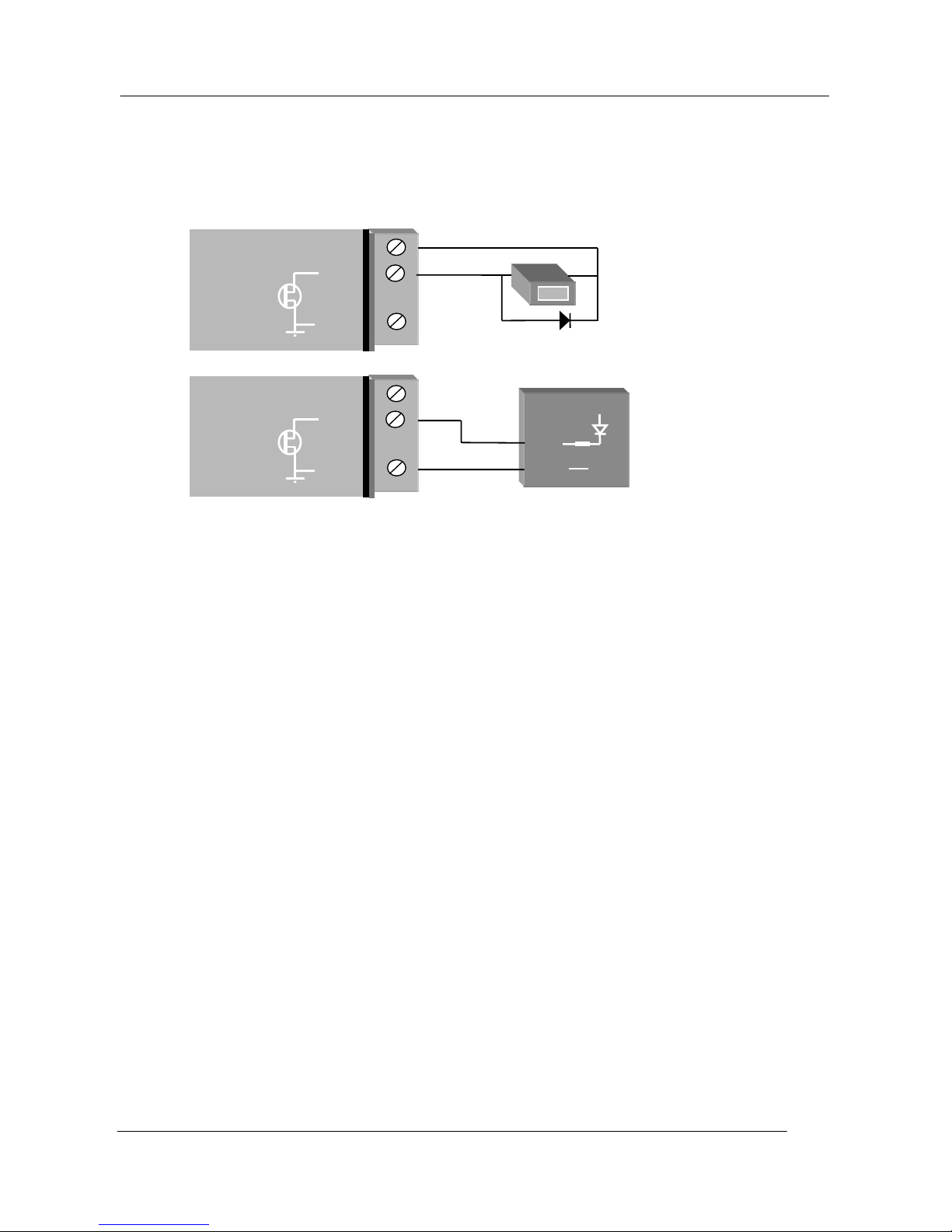
A single FET output to common rated at 30VDC, 500 mA is provide for the pulse output "PO".
This output accurately recreates the pulses counted at a pulse input at a 105-1 or 105-2 module.
If the counter device requires a voltage pulse signal (such as electronic or elector-mechanical
counters), use the 24V analog loop supply, or the 12V BAT supply for the voltage source. Use a
by-pass diode if the counter is inductive.
Some devices such as PLC counter modules power the pulse loop. For these devices, connect to
the PO and COM terminals of the 105U. The COM terminal will connect a ground/earth to the
external device. If this is not suitable, use a solid state relay to isolate the external device.
Although the count is accurately re-created, the rate of output pulses may not accurately reflect the
input rate. The actual input pulse rate may be configured to appear at an analogue output if
required. Note that the pulse rate and accumulated value will remain accurate even if a period of
communications failure has occurred. The maximum output rate is 100 Hz. If a high speed pulse
input is used (more than 100 Hz) on PI1 of a 105-2 module, the pulse input count should not be
transmitted to a PO on the 105-1 or DO on the 105-3 without configuring the divide-by-10 function
(on the 105-2 or 105-4 module)
2.4.9 Pulse Output (105-3 and 105-4)
The first four digital outputs on the 105-3 and 105-4 modules may also be used as pulse outputs.
The outputs are FET output to common rated at 30VDC, 500 mA. The outputs will provide a pulse
signal of up to 100 Hz. The outputs accurately recreate the pulses counted at pulse inputs at a 1051, 105-2 or 105-4 module.
Although the count is accurately re-created, the rate of output pulses may not accurately reflect the
input rate. The actual input pulse rate may be configured to appear at an analogue output if
required. Note that the pulse rate and accumulated value will remain accurate even if a period of
communications failure has occurred.
_
+
+24V
PO
COM
105U
Use by-pass
diode if counter
is inductive.
COUNT
+
_
+
_
+24V
PO
COM
105U
Use solid-state
relay isolator if
voltages are not
compatible
Page 22
105 Radio/Serial Telemetry Module User Manual
Page 22 © January 2004
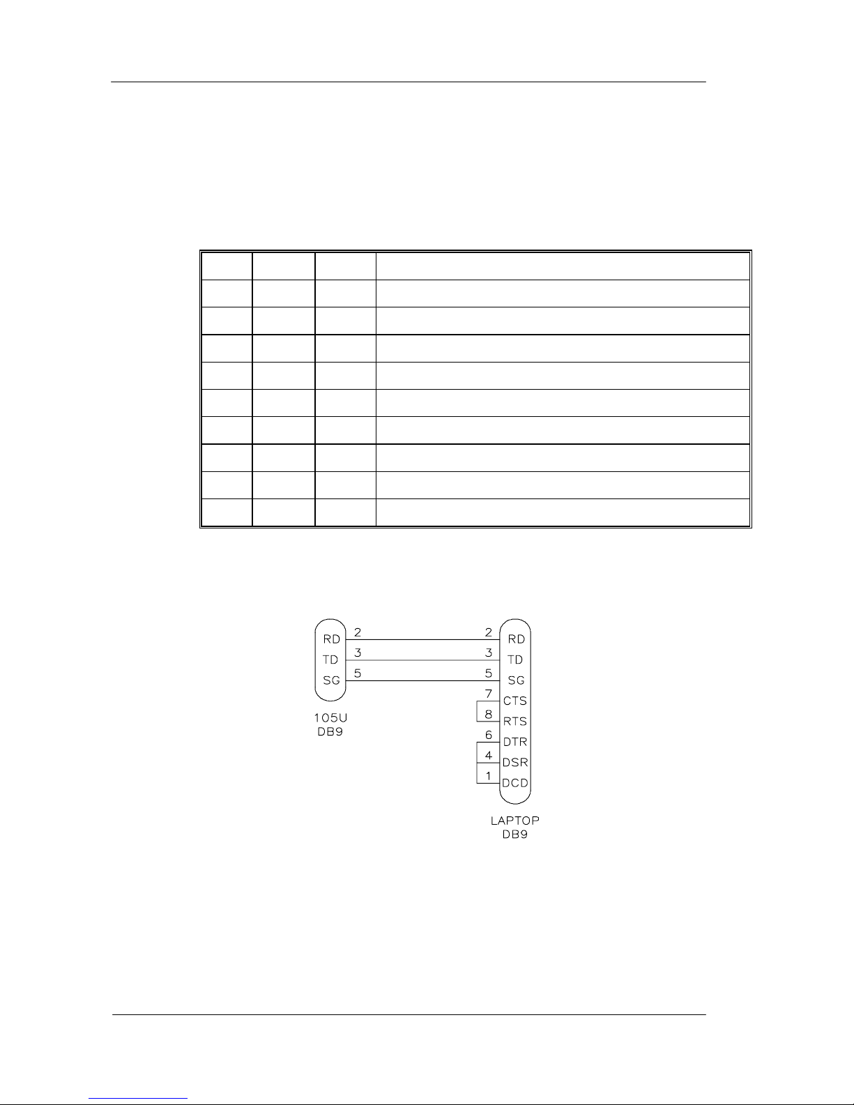
2.4.10 RS232 Serial Port
The serial port is a 9 pin DB9 female and provides for connection to a terminal or to a PC for
configuration, field testing and for factory testing. This port is internally shared with the RS485 ensure that the RS485 is disconnected before attempting to use the RS232 port. Communication is
via standard RS-232 signals. The 105 is configured as DCE equipment with the pin-out detailed
below. The serial port communicates at a baud rate of 9600 baud, 8 bits, no parity, one stop bit.
Pin Name Dirn Function
1 DCD Out Data carrier detect - not used
2 RD Out Transmit Data - Serial Data I nput (Hig h = 0, Low = 1)
3 TD In Receive Data - Serial Data Output (H ig h = 0, Low = 1)
4 DTR In Data Terminal Ready - not used
5 SG - Signal Ground
6 DSR Out Data Set Ready - not used
7 RTS In Request to Send - not used
8 CTS Out Clear to send - not used
9 RI - Ring indicator - not used.
An example cable drawing for connection to a laptop is detailed below:
MALE FEMALE
2.4.11 RS485 Serial Port
The RS485 port provides for communication between multiple 105 units using a multi-drop cable.
Up to 32 units may be connected in each multi-drop network. Each multi-drop network may have
one unit providing radio communications with other units in the system. The RS485 feature allows
local hubs of control to operate without occupying radio bandwidth required for communication
between remotely sited units.
Page 23
Chapter Two Installation
man_105_2.9.doc Page 23
The RS485 Communications format is 9600 baud, 8 data bits, one stop bit, no parity. Note that
the RS485 port is shared internally with the RS232 port - disconnect the RS232 cable after
configuration is complete.
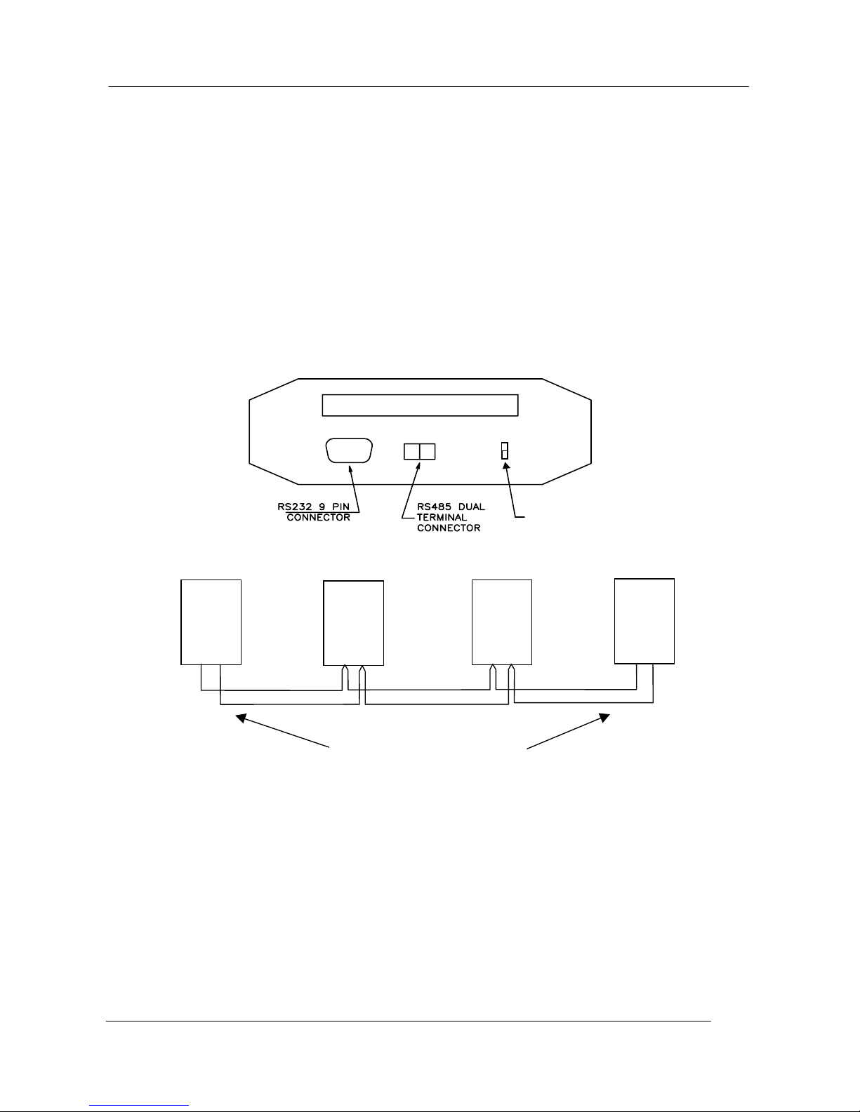
RS485 is a balanced, differential standard but it is recommended that shielded, twisted pair cable be
used to interconnect modules to reduce potential Radio Frequency Interference (RFI). An RS485
network should be wired as indicated in the diagram below and terminated at each end of the
network with a 120 ohm resistor.
The 105U modules include a terminating resistor on-board. If the 105U module is the first or last
module in the RS485 chain, then the terminating resistor may be connected by operating the single
DIP switch in the end-plate next to the RS485 terminals. “On” or “down” means that the resistor is
connected. The 105S Modules also have a switchable resistor.
TERMINATING
RESISTOR SWITCH
+
-
2.4.12 Connecting 105S Modules to 105U Modules
105S modules connect to a 105U via the RS485 port on each module - refer to section 2.4.11. Up
to 31 x 105S modules can be connected to a 105U module. This number is reduced for 105S-3 and
–4 modules, as these modules use two unit addresses (refer to chapter 4 of this manual).
The 105S modules can be mounted next to the 105U module, or they can be remote from the 105U.
The reliable distance for a RS485 multi-drop line depends on the shielding of the wire and how
close it is installed to electrical noise sources - distances of more than 1 km can be achieved by
good installation methods. External RS485 isolators are recommended if the earth potential
difference between modules is greater than 7V.
105U
105S
RS485
A B
105U
105S
RS485
A B
105U
105S
RS485
A B
105U
105S
RS485
A B
Activate resistor-connection
switch at both end
modules
Page 24
105 Radio/Serial Telemetry Module User Manual
Page 24 © January 2004
Chapter Three OPERATION
3.1 Power-up and Normal Operation
When power is initially connected to the 105 module, the module will perform internal
diagnostics to check its functions. The following table details the status of the indicating
LED’s on the front panel under normal operating conditions.
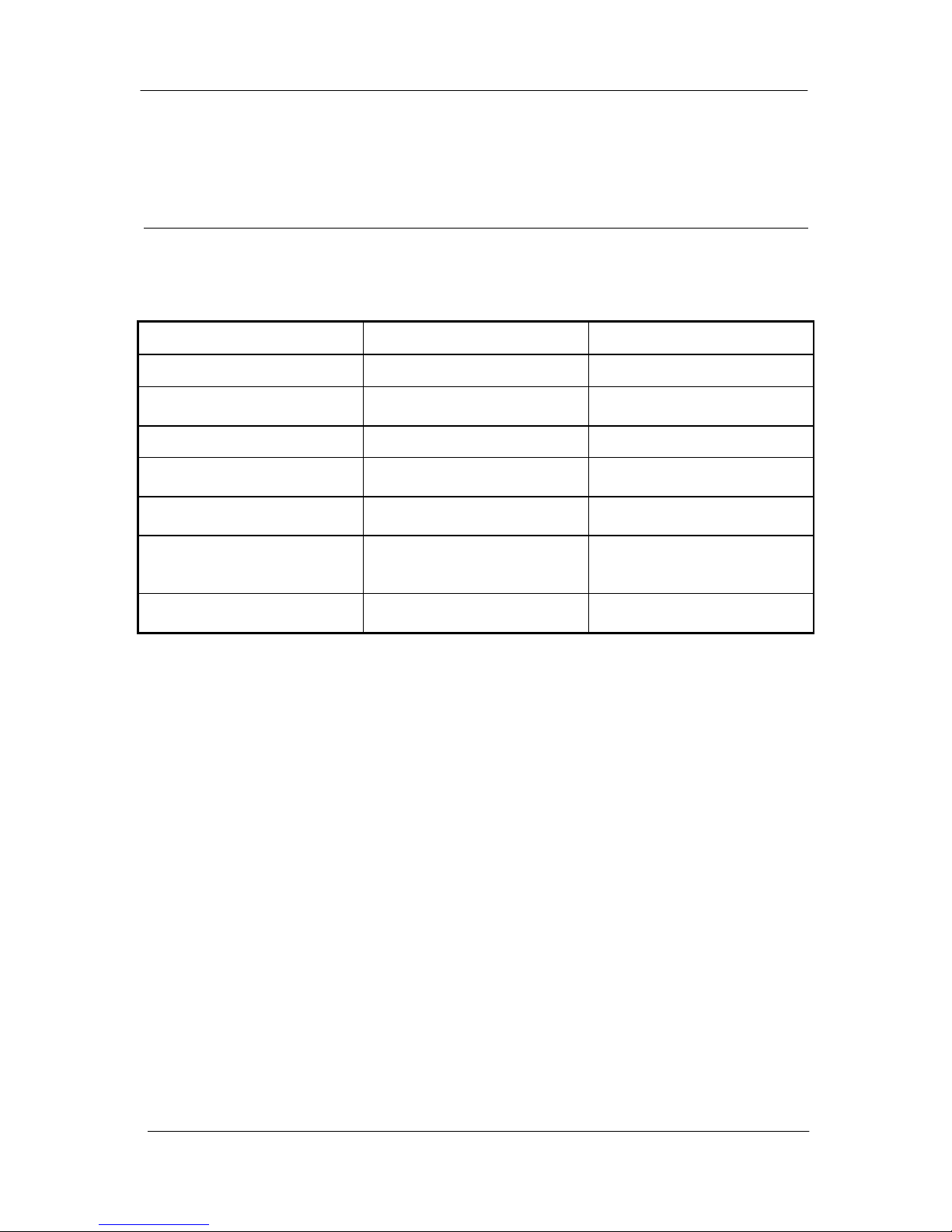
LED Indicator Condition Meaning
OK On Normal Operation
RX Occasional flash Radio Receiving, or
Activity on serial ports
RX Flashes continuously Configuration Mode
RX On Button press when entering
Configuration Mode
TX
(only on 105U units)
Occasional flash Radio Transmitting
PWR On Supply voltage available
from Solar Panel or
SUP1/SUP2
OK Flashes every 5 seconds +24V Supply
overloaded
Additional LED’s provide indication of the status of digital inputs and outputs. LED’s display
the status of each digital input (lit for active), and LED’s display the status of each digital output
(lit for active). Other conditions indicating a fault are described in Chapter Six
Troubleshooting.
The 105 module monitors the power supply and provides status of supply failure and battery
low voltage for "mapping" to one of the module's own outputs or transmitting to a remote
output. When the 105 module is powered from a normal supply (i.e. via either of the “SUP”
terminals), the PWR LED indicator is lit. When the 105 modules is powered from a solar
panel and battery, the PWR LED indicator is lit only when the charge current is available (i.e.
when the solar panel is receiving light). In the event of excessively low battery voltage
(10.8V), the OK LED will go off, the unit will automatically set all outputs off, and disable
the +24V analogue loop supply. the OK LED will turn on again after the battery voltage
exceeds 11.3V. This enables installations to be configured so that the battery current drain is
minimised in the event of extended mains failure, reducing the possibility of deep discharge
of batteries.
3.1.1 Communications
If transmissions are not successful, then the 105 module will re-try up to four times at random
intervals to transmit the message. If communications is still not successful, the “Comms Fail”
internal status will be set. In the default configuration, this will have no consequence and the
Page 25
Chapter Three Operation
man_105_2.9.doc Page 25
105 module will continue to attempt to transmit to the remote module every ten minutes. For
critical applications, this status can be configured to be reflected to an output on the module
for alert purposes. The outputs on the module may also be configured to reset after a
specified timeout (digital outputs reset to “off”, analogue outputs reset to 0 mA) allowing the
system to turn off in a controlled manner e.g. a pump will never be left running because of a
system failure.
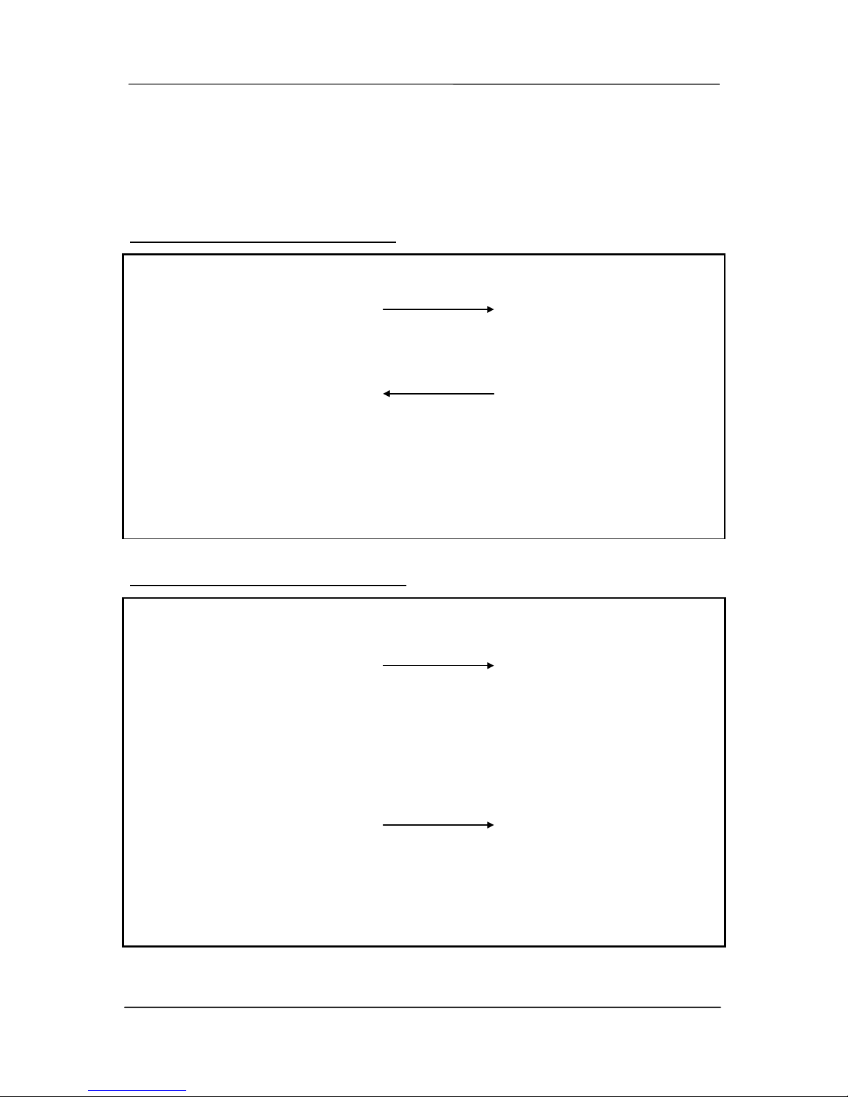
Example of Successful Communications
Local Unit
• Listen to ensure channel is clear
Remote Unit
• If clear, transmit message
TX LED flashes if radio
RX LED flashes if RS485
• Receive message
RX LED flashes
Check message for integrity
• RX LED flashes
• Acknowledgement received okay -
communication complete
• If message okay, transmit it back
as acknowledgement
TX LED flashes if radio
RX LED flashes if RS485
Outputs updated as per
message received.
Example of unsuccessful communications
Local Unit
• Listen to ensure channel is clear
Remote Unit
• If clear, transmit message
TX LED flashes if radio
RX LED flashes if RS485
• Receive message
RX LED flashes
Check message for integrity
Message corrupted - do
nothing
• No acknowledgement received
• Retry up to four times
• Still no acknowledgement
“Comms fail” status to remote unit
set
If status is mapped to an output,
set output
• If no update received for an
output within watchdog timeout,
check to see if the output is
configured to reset
• Reset outputs if configured
(4)
Page 26
105 Radio/Serial Telemetry Module User Manual
Page 26 © January 2004
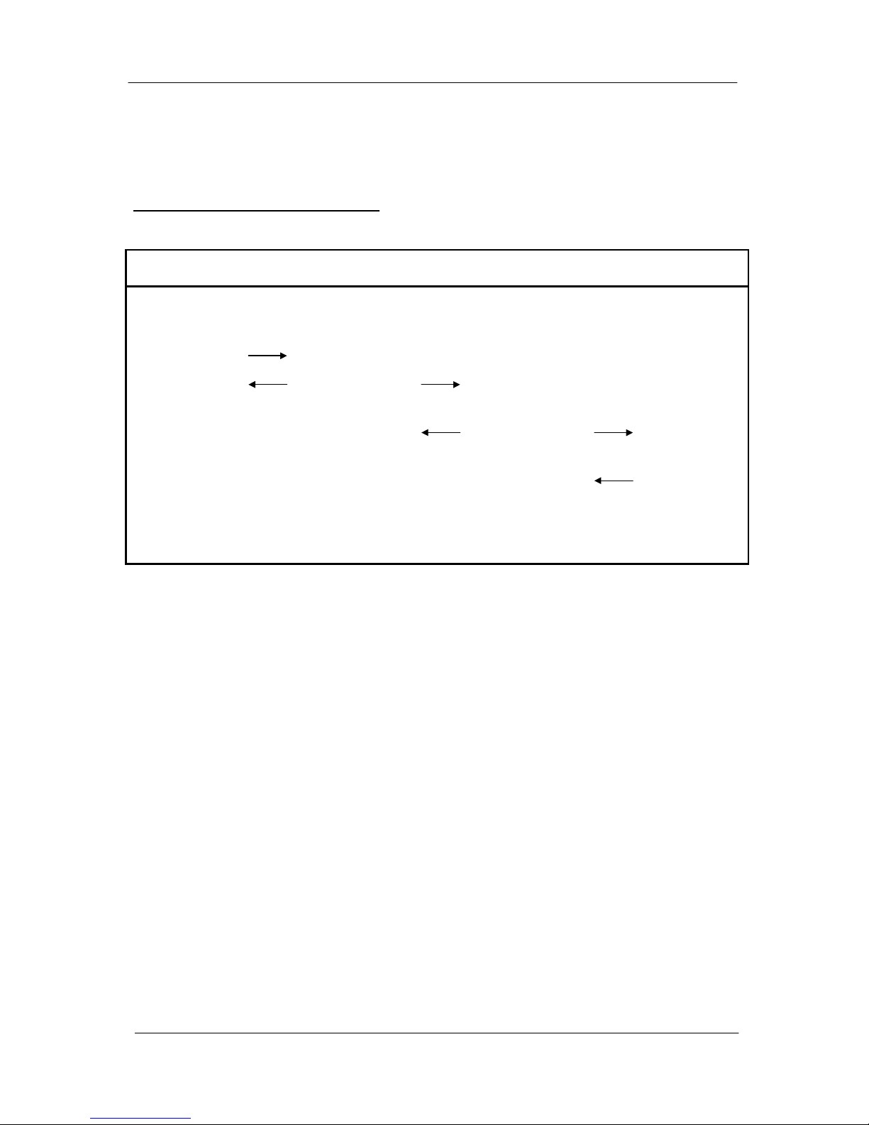
Repeaters can be used in a system to increase range. Each 105U unit can be configured to
act as a repeater. When configuring an input to be mapped to an output, the communications
path to the output unit, including the repeater addresses is specified. The 105U acts as a
digital repeater, that is, the signal is decoded and then retransmitted “as new”.
Example Repeater Communications
Unit A DI 1 mapped to Unit D DO1 via Units B & C
Unit A Unit B
Repeater
Unit C
Repeater
Unit D
• DI 1 is turned
on
• Transmit
• Receive
Acknowledge
• Receive
• Transmit on with
Acknowledge
• Receive
Acknowledge
• Receive
• Transmit on with
Acknowledge
• Receive
Acknowledge
• Receive
• Transmit
acknowledge
• DO 1 is
turned on
3.1.2 Change of state conditions
The 105 module transmits a data message whenever it detects a "change-of-state" on one of
its input signals. A "change-of-state" of a digital or digital internal input is a change from
"off" to "on" or vice-versa provided the change is sustained for 0.5 second (i.e. 0.5 second
debounce). The debounce delay is configurable.
In addition to "change-of-state" transmissions, each module will transmit the status of each
input to its corresponding output every ten minutes (configurable). These updates mean that
the outputs are set to the current input values regularly, even where no “change-of-state” has
occurred. These update transmissions increase the accuracy of the output and give extra
system reliability. Update times can be configured from 10 seconds to 16 minutes on the
105-1, -2 and –3 modules, and from 10 seconds to 5 days on the 105-4. Note that the
accuracy of the time period is approx 0.5%.
Analogue Change-of-state
A "change-of-state" for an analogue input, battery voltage or pulse input rate is a change in
value of the signal of 3% (configurable) since the last transmission. Note that the sensitivity
of 3% refers to 3% of the analogue range, not 3% of the instantaneous analogue value. That
is, if an analogue input changes from 64% (14.24 mA) to 67% (14.72 mA), a "change-ofstate" will be detected. This “change-of-state” sensitivity is configurable between 0.8% and
50%.
Analogue inputs are digitally filtered to prevent multiple transmissions on continually varying
Page 27
Chapter Three Operation
man_105_2.9.doc Page 27
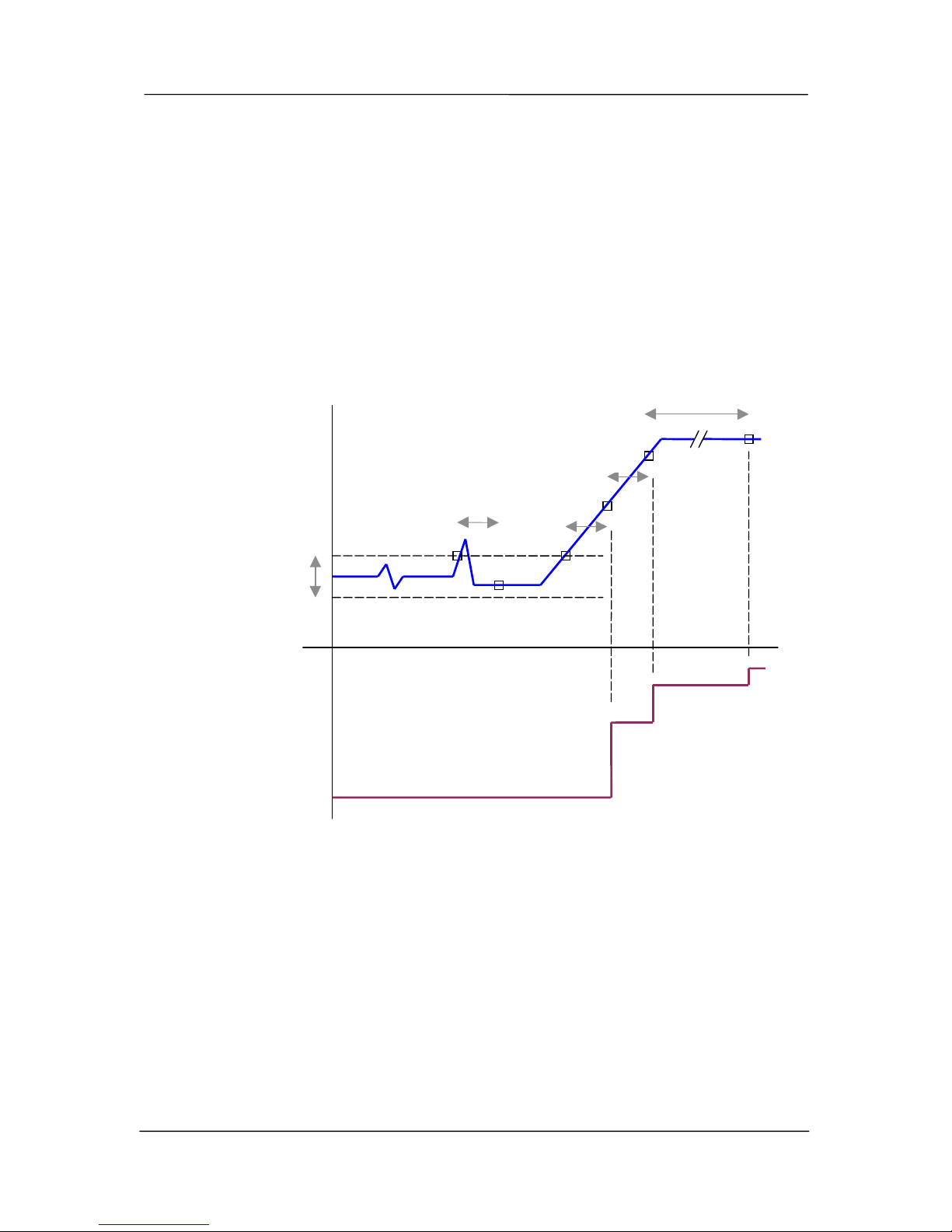
or "noisy" signals. The input is filtered with a 1 second time constant and a 1 second
debounce. The analogue outputs are filtered with a 1 second time constant. An example
explaining the interaction of these figures is shown below. In general, the following may be
used as a rule of thumb for calculating the appropriate sensitivity required for a given
application:
Instantaneous change of 2 x sensitivity on input → 3 second output response
Instantaneous change of 10 x sensitivity on input → 5 second output response
The analogue inputs have 15 bit resolution and 0.016mA accuracy.
An example of an analogue input and how the output follows it is shown below:
Pulse input change of state
Pulse input counts do not use “change-of-state” transmissions. Instead, accumulated pulse
input counts are transmitted at set intervals. The default period is 1 minute and is
E
0.5 sec
0.5 sec
0.5 sec
SENSITIVITY
BAND
A B C D
UPDATE
TIME
INPUT
SIGNAL
OUTPUT
SIGNAL
TIME
A No transmission as the sensitivity band was not exceeded
B The sensitivity band was exceeded, however the input returned to within the
sensitivity band before the 0.5 sec debounce time - no transmission
C Transmission occurs 0.5 sec after the sensitivity band is exceeded.
D Another transmiss ion 0.5 sec later as the input has changed by more than
the sensitivity band
E The input has not changed by more than the sensitivity, however the update
time has ela
p
sed since D.
Page 28
105 Radio/Serial Telemetry Module User Manual
Page 28 © January 2004
configurable. The absolute pulse count is transmitted. If the PI is transmitted to a PO on a
105 module, then the pulse outputs are re-created from the accumulated pulse count.
Rollovers of the pulse count thru zero are catered for. If a transmission is missed, the pulse
output will still be re-created when the next accumulated value is transmitted. This ensures
that no pulses are lost due to communications failures. If the PI is transmitted to a 105U-C
interface module, then the accumulated pulse count is stored in the 105U-C for interfacing to
the host device.
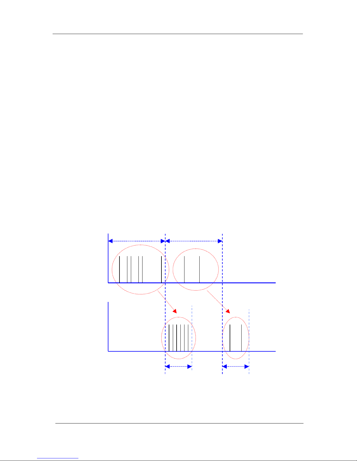
The following diagram shows how pulse inputs are re-created as pulse outputs. For pulse
outputs, the 105 module keeps two counters in memory - the pulse input count received
from the remote 105 module, and the count of output pulses. When the 105 receives an
update of the input pulse count, it will output pulses until the output pulse count is the same
as the input pulse count. The output pulse will be output evenly over the pulse output update
time which is configured in the module. For example, assume that 105 module receives a
pulse input update message from the remote 105 module, and the difference between the
pulse input count and the pulse output count is 12 pulses. The 105 will then output the 12
pulses evenly over the next minute (if the pulse output update time is 1 minute).
The default values for the pulse input update time and pulse output update time is 1 minute.
In this case, the output pulses are effectively 1 minute behind the input pulses. These update
times may be changed by the user. The pulse output update time should not be set to be more
than the pulse input update time. Note that the maximum pulse rate for both inputs and
outputs is 100Hz.
Input
Pulses
Time
Output
Pulses
PI update time
PO update time
Time
As well as accumulating the pulse input, the 105 module will also calculate the rate of
pulses. Pulse rates are treated as an “internal” analogue input and are configured with
analogue sensitivities for change-of-state transmissions. The maximum pulse rate
Page 29

Chapter Three Operation
man_105_2.9.doc Page 29
corresponding to 20mA output may be configured by the user.
3.1.3 Analogue Set-points
On 105-1 modules, the “AI 1” input may be used to trigger the analogue set-point status.
High set point and low set point levels are configurable. This set-point status turns ON when
the analogue input moves below the low level, and turns OFF when it moves above the high
level. The high level must always be greater than, or equal to, the low level set point. This
set-point status may be mapped (inverted, if required) to any output in the network. The setpoint status is effectively an internal digital input.
On 105-2 modules, analogue inputs 1 - 4 have set-point values for controlling digital outputs.
The set-point operation works as for the 105-1 module.
3.1.4 Start-up Poll
After a 105 module has completed its initial diagnostics following power up, it will transmit
update messages to remote modules based on the values of the module’s inputs. The
module’s outputs will remain in the reset/off/zero condition until it receives update or
“change-of-state” messages from the remote modules.
The 105 module can transmit a special “start-up poll” message to another module. The
remote module will then immediately send update messages to this module such that its
outputs can be set to the correct value. Start-up polls will only occur if they are configured.
It is necessary to configure a start-up poll to each remote module which controls the module’s
outputs. For further information, refer to Chapter 4 Configuration.
3.1.5 Communications Failure (CF)
The internal communications failure (CF) status is set if a module does not receive an
acknowledgement message after five attempts at transmitting a message. The CF status may
be configured to set a local digital output for an external alarm.
Although the CF status can set an output, it will not reset the output. That is, once
communications is re-established (and the CF status is reset), the output will stay “on”. The
Reset Output feature (see below) is used to reset the output.
The output will reset only when no communications failures occur within the configured
“Reset Output Time” for the output that CF status is mapped to. Note that if the reset output
time is not enabled, the CF status will remain set forever, once an unsuccessful transmission
occurs. See Chapter 4 Configuration for further details.
3.1.6 Resetting Outputs
Each digital and analogue output may be individually configured to reset if that output has not
received a change-of-state or an update message within a certain time period. Generally this
time is set to twice the update period, so at least one update can be missed before an output is
reset.
In most cases it is desirable to reset outputs which are controlling equipment if there is a
system failure, however alarm or indication outputs are not reset so the last valid indication
remains shown. See Chapter 4 Configuration for further details.
Page 30

105 Radio/Serial Telemetry Module User Manual
Page 30 © January 2004
3.2 System Design Tips
The following tips will help to ensure that your system operates reliably.
3.2.1 System Dynamics
It is important to be aware of the dynamics of the 105 system. Digital inputs have a minimum
“debounce” delay (default 0.5 sec) - that is, a change message will not be sent for 0.5 sec
after a change has occurred. Analogue inputs and outputs have time delays of 1 to 2 seconds.
Messages transmitted via serial link are received in less than 20 mSec, however a message
sent by radio takes approx 60 mSec.
These delays are not significant is most applications, however if your application requires
faster responses, then the above delays need to be considered.
3.2.2 Radio Channel Capacity
Messages sent on a cable link are much faster than on a radio channel, and the capacity of the
radio channel must be considered when designing a system. This becomes more important as
the I/O size of a system increases.
The 105 modules are designed to provide “real-time” operation. When an input signal
changes, a change message is sent to change the output. The system does not require
continuous messages to provide fast operation (as in a polling system). Update messages are
intended to check the integrity of the system, not to provide fast operation. Update times
should be selected based on this principle. The default update time is 10 minutes - we
recommend that you leave these times as 10 minutes unless particular inputs are very
important and deserve a smaller update time.
It is important that radio paths be reliable. For large systems, we recommend a maximum
average radio channel density of 100 messages per minute, including change messages and
update messages. We suggest that you do not design for an average transmission rate of
greater than 40 per minute - this will give a peak rate of approx 100 per minute. Note that
this peak rate assumes that all radio paths are reliable - poor radio paths will require re-try
transmissions and will reduce the peak channel density. If there are other users on the radio
channel, then this peak figure will also decrease.
The 105 modules will only transmit one message at a time. If re-tries are necessary, another
message cannot start. The time between re-tries is a random time between 1 and 5 seconds.
The time for five tries is between 5 and 21 seconds. Another message cannot be sent until the
last one has finished. This delay will obviously have an affect on a busy system.
3.2.3 Radio Path Reliability
Radio paths over short distances can operate reliably with a large amount of obstruction in the
path. As the path distance increases, the amount of obstruction which can be tolerated
decreases. At the maximum reliable distance, “line-of-sight” is required for reliable
operation. If the path is over several kilometres (or miles), then the curvature of the earth is
also an obstacle and must be allowed for. For example, th e earth curvature over 10 km is
Page 31

Chapter Three Operation
man_105_2.9.doc Page 31
approx 4m, requiring each antenna to be elevated at least 5m to achieve “line-of-si ght” even
if the path is flat.
A radio path may act reliably in good weather, but poorly in bad weather - this is called a
“marginal” radio path. If the radio path is more than 20% of the maximum reliable distance
(see Specification section for these distances), we recommend that you test the radio path
before installation. Each 105U module has a radio path testing feature - refer to section 6.2
of this manual.
There are several ways of improving a marginal path :-
• Relocate the antenna to a better position. If there is an obvious obstruction causing the
problem, then locating the antenna to the side or higher will improve the path. If the radio
path has a large distance, then increasing the height of the antenna will improve the path.
• Use an antenna with a higher gain. Before you do this, make sure that the radiated power
from the new antenna is still within the regulations of your country. If you have a long
length of coaxial cable, you can use a higher gain antenna to cancel the losses in the
coaxial cable.
• If it is not practical to improve a marginal path, then the last method is to use another
module as a repeater. A repeater does not have to be between the two modules (although
often it is). If possible, use an existing module in the system which has good radio path to
both modules. The repeater module can be to the side of the two modules, or even behind
one of the modules, if the repeater module is installed at a high location (for example, a
tower or mast). Repeater modules can have their own I/O and act as a “normal” 105U
module in the system.
3.2.4 Design for Failures
All well designed systems consider system failure. I/O systems operating on a wire link will
fail eventually, and a radio system is the same. Failures could be short-term (interference on
the radio channel or power supply failure) or long-term (equipment failure).
The 105 modules provide the following features for system failure :-
• Outputs can reset if they do not receive a message within a configured time. If an output
should receive an update or change message every 10 minutes, and it has not received a
message within this time, then some form of failure is likely. If the output is controlling
some machinery, then it is good design to switch off this equipment until communications
has been re-established.
The 105 modules provide a “drop outputs on comms fail” time. This is a configurable
time value for each output. If a message has not been received for this output within this
time, then the output will reset (off, in-active, “0”). We suggest that this reset time be a
little more than twice the update time of the input. It is possible to miss one update
message because of short-term radio interference, however if two successive update
messages are missed, then long term failure is likely and the output should be reset. For
example, if the input update time is 3 minutes, set the output reset time to 7 minutes.
• A 105 module can provide an output which activates on communication failure to another
module. This can be used to provide an external alarm that there is a system fault.
Page 32

105 Radio/Serial Telemetry Module User Manual
Page 32 © January 2004
3.2.5 Indicating a Communications Problem
There are two ways to provide an indication of communications problems.
Fail to transmit alarm. The first is to map the internal CF status to a local output, to
generate a “fail-to-transmit” alarm. The configured output will activate when a comms fail
occurs - that is, when the module attempts to transmit a message five times without an
acknowledgement. This method provides an indication immediately an attempt to transmit a
message fails. If you want the radio path to be “tested” regularly, then you need to configure
the update times such that transmissions occur regularly (however do not overload the radio
channel).
Notes regarding this method:
1. Each CF mapping corresponds to only one remote address - you need to make separate
mappings for each remote address. You can map the CF for each remote module to a
separate output, or to the same output.
2. You need to reset the comms fail output using the “reset output” parameter. Select a reset
time which is greater than the effective update time period. For example, if there are four
inputs mapped from module #1 to module #2, each with a 10 minute update, then you
would expect at least four transmissions in each 10 minute period. At module #1, a
comms fail for #2 is mapped to DO1. If you set the “reset time” for DO1 to 10 minutes,
then there will be at least four transmissions made during the reset period - that is, the
output will only reset when the communications has been successful four times.
3. This method will not work for radio links with repeaters. If a repeater is used, you will
need to use the second method described below.
Fail to receive alarm. The second method is to set up a “comms OK” output using the
“Reset Outputs” function. The output is normally on, indicating “comms OK”, and will reset
if the module does not receive a message from the remote module within the configured reset
time.
Consider a link between module #1 and #2, and assume that you want a “comms OK” output
at #1. At #2, map an unused input to an output at #1 such that the output is normally active
(‘on”). If there is no spare inputs at #2, you can use an internal input such as “low voltage
status”. You will need to invert the mappings such that the output is normally on (because
the input is normally off).
At #1, configure a reset time for the output. The reset time should be greater than the update
time for the mapping at #2. If #1 fails to receive update messages from #2, then the output
will reset, indicating a communications failure. Notes regarding this method:
1. This method will work with repeaters in the link.
2. The “comms OK” output is fail-safe - if module #1 fails, then the output will reset
indicating a problem.
3. You should use separate outputs to indicate “comms OK” of different remote modules.
4. It is recommended that you set the reset time at #1 to more than twice the update time of
the mapping at #2. This means that the comms OK output will only reset if #1 misses two
consecutive updates from #2.
Page 33

Chapter Three Operation
man_105_2.9.doc Page 33
3.2.6 Testing and Commissioning
We recommend that you set-up and test the system with all of the modules together before
you install the modules. It is much easier to find a configuration problem.
When the system is configured, record the radio signal strength and background noise level
for each radio link. If there are future communications problems, you can compare the
present measurements to the as-commissioned values.
3.3 Security Considerations
There are three dimensions of security considerations:
1. Failure to operate when required - or “operational reliability”.
The features discussed above optimise operating reliability. Using an acknowledgement
and re-try protocol ensures that the transmitting module is aware whether the transmitted
message has been transmitted reliably. The “fail to transmit” and “fail to receive” alarms
provide indication if the radio link has failed to operate.
2. Mal-operation, or operating when not requested.
This problem occurs when an output is “triggered” by the wrong radio device. The 905U
modules use frequency encoding and a very secure addressing system to ensure this does
not occur. An additional security level using data encryption can also be selected.
3. Malicious operation, or “hacking”
This is the problem most associated with security concerns - the ability for someone to
access information from a radio system by “listening-in”, or to cause damage by
transmitting radio messages to force outputs.
A security option can be selected during the module configuration to protect against this.
The security option (if selected) adds data encryption to radio messages. Modules in the
same system are automatically configured with the encryption key, such that only these
modules can understand each other. “Foreign” modules will hear the messages, but
cannot decrypt the messages. For more information, refer to section 4.3.7.
Page 34

105 Radio/Serial Telemetry Module User Manual
Page 34 © January 2004
Chapter Four CONFIGURATION
4.1 Introduction
The 105 modules are configured by connecting a computer (PC) using the 105 Configuration
Software programme. The same software program is used to configure 105U-C and 105U-G
modules - for more information, refer to the separate User Manuals.
Each 105 module is configured with a system address and a unit address. The system address
is common to every module in the same system, and is used to prevent "cross-talk" between
modules in different systems. Separate networks with different system addresses may operate
independently in the same area without affecting each other. The system address may be any
number between 1 and 32 767. The actual value of the system address is not important,
provided all modules in the same system have the same system address value. A system
address of zero should not be used. The configuration program automatically offers a
random number for the system address - you can change this to any number in the valid
range but we recommend that you use the random number.
Each module must have a unique unit address within the one system. A valid unit address is
1 to 127. A network may have up to 95 individual modules communicating via radio (unit
addresses 1 to 95), each with up to 31 modules communicating via RS485 (unit addresses 96
to 127). In the network, any individual input signal may be "mapped" to one or more outputs
anywhere in the system. The unit address determines the method of communication to a
module. Any module with a unit address between 96 and 127 will communicate by RS485
only. Other units with a unit address below 95 may communicate by radio or RS485 - the
unit will determine which way to communicate depending upon the unit address of the
destination module. For example, Unit 31 will talk to Unit 97 by RS485 only, but will talk to
unit 59 by radio only. 105S units must always have a unit address between 96 and 127 as
serial communication is the only method of communication available. A unit address of
zero should not be used.
The four different products in the range can be used together in the same system, as well as
105U-C and -G modules. Inputs to one product type can be transmitted to outputs of another
product type. For example, an analogue input to a 105-2 may be transmitted to an analogue
output of a 105-1 or 105-3. Repeaters may be any product type.
The 105-1 and 105-2 modules require only one unit address. The 105-3 and 105-4 modules
use two addresses, however only one unit address has to be entered. The 105-3 and 105-4
modules require two addresses because of the large number of output channels. If the
“entered" unit address is an even number, then the second address is the next number. If the
"entered" address is an odd number, then the second address is the previous number. So the
two addresses are two subsequent numbers, starting with an even number. If a 105-3 module
is given a unit address of 10, then it will also take up the unit address 11 and will accept
messages addressed to either 10 or 11. It is important to remember this when allocating unit
addresses to other modules in the system.
Warning - do not allocate the address number 1 to a 105-3 or 105-4.
Page 35
Chapter Four Configuration
man_105_2.9.doc Page 35
In addition to these network configurations, operational parameters called User Options may
be configured to change the features of the 105 operation.
4.2 Easy Configuration Using Default Settings
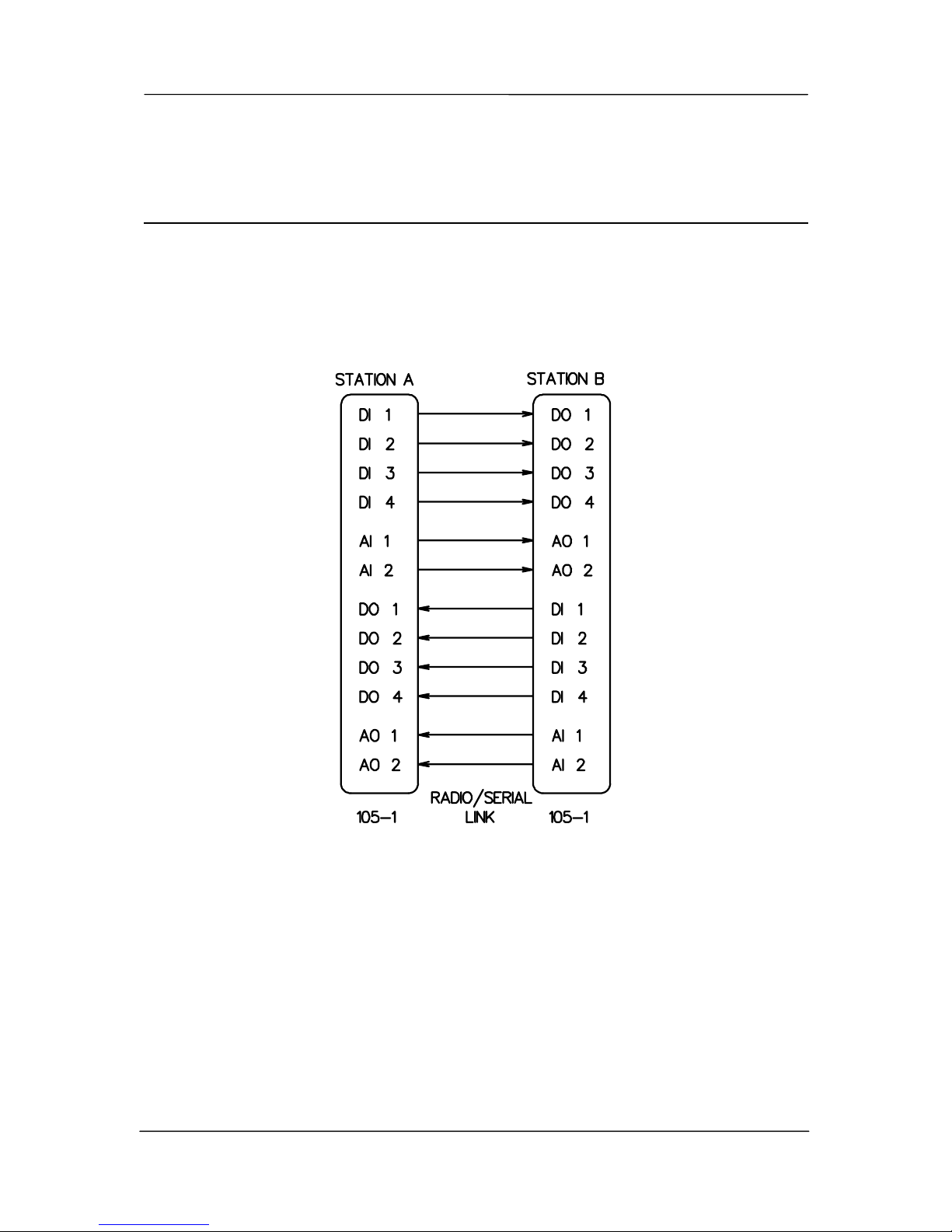
If your application requires only a single pair of 105 modules, communicating via radio or serial
link, default settings may satisfy your needs. If so, no configuration is required. Essentially, all
inputs at Module A are reflected at the corresponding outputs at Module B. All inputs at
Module B are reflected at the corresponding outputs at Module A.
For 105-1 modules, the default configuration is as follows :-
In this configuration, the “PO” Pulse output is inactive and no special action is taken on
“Comms fail”, “Mains fail” or “Battery Low”. “DI 1” is configured as a digital and not a pulse
input.
Page 36
105 Radio/Serial Telemetry Module User Manual
Page 36 © January 2004
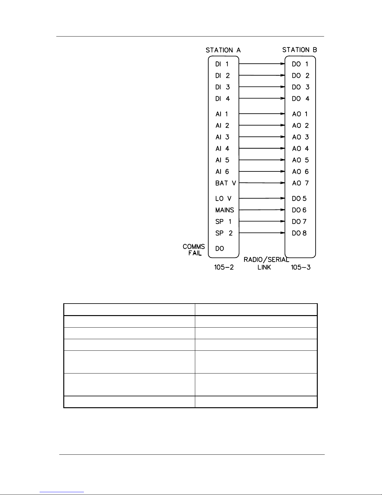
For 105-2 and 105-3 modules, the
default configuration is as follows :-
The following table details the default va lues f or User Options:
Option Factory Set Value
Update transmissions Every 10 minutes
Analogue Change- of-state sensitivity 3%
Reset outputs on Comms fail No
Analogue Setpoints (if mapped) Low Set point = 30%
High Set point = 75%
Pulse Output Rate Scaling
(if Pulse Rate is mapped)
100 Hz
Digital Input Debounce Time 0.5 seconds
If any of the above values are not appropriate to your system, Section 4.4 below will detail how
to change one or all of the above variables.
Page 37

Chapter Four Configuration
man_105_2.9.doc Page 37
4.3 105 Configuration Software
This chapter describes installation and operation of configuration software for the 105 radio
and serial telemetry modules. The configuration software runs on a conventional PC as a
Windows application. The software creates a configuration file which can be loaded into a
105 module via RS232. The configuration software also allows the configuration of a 105
module to be loaded for display and modification. Configuration files are created and stored
in project directories.
Configuration of 105 modules consists of entering I/O mappings, and selecting User Options.
An I/O mapping is a link between an input on the module being configured and an output on
another module. A mapping has the form :-
DI3 → Out2 at 4 via 3, 11
This mapping links DI3 on this module to output channel 2 on the module with address 4,
and modules 3 and 11 are repeaters.
User Options may be selected to change the configuration of specific features.
Mappings configured to a 105U-C have the form :-
AI2 → I/O Reg 1036 at 10 via 7
This mapping links AI2 on a 105 module to I/O Register 1036 in a 105U-C with address 10.
Module #7 is used as a repeater. The host device connected to the 105U-C can read the I/O
register.
4.3.1 Hardware and Software Requirements
The configuration software is available on a CD, and needs to be installed on your PC before
you can use it. The CD contains a setup file called setup.exe. Select the configuration
software window on the Product CD and an installation Wizard will guide you through the
installation procedure. To upload and download configuration files to a module, you will
need a RS-232 serial cable as shown below.
105 End PC End
DB9 Male DB9 female
1 1
2 2
3 3
4 4
5 5
6 6
7 7
8 8
9 9
Required
Optional
Page 38
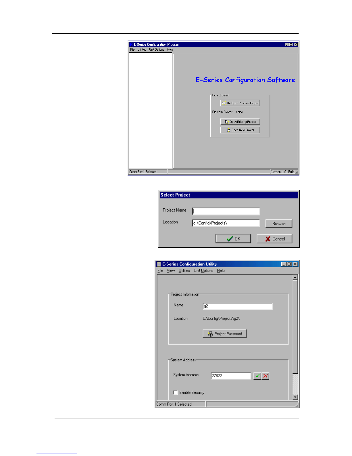
105 Radio/Serial Telemetry Module User Manual
Page 38 © January 2004
4.3.2 Programme
Operation
Start the software by
either clicking on the
start bar and navigating
to the Configuration
menu or by running
ESERIES.EXE
The Initial screen will
appear. The
configuration is
performed for a
complete system. The
necessary configuration
stages are :
" select system name
and system address
" select individual units and unit
addresses
" configure I/O mappings for each
unit
" configure user options for each
unit
" compile the system, which
generates configuration files for
each unit
" load the configuration files into
each unit.
From the initial screen, you can
select an existing project, or start a
new project. The name of the
project will create a new directory
which will eventually contain the
configuration files for the modules
in this system.
When you have selected the project,
a screen wil appear where you may
enter the system address.
If you are editting an existing
project, the system address will
already have been entered. Do not
change the system address unless
you are going to re-programme all of
Page 39
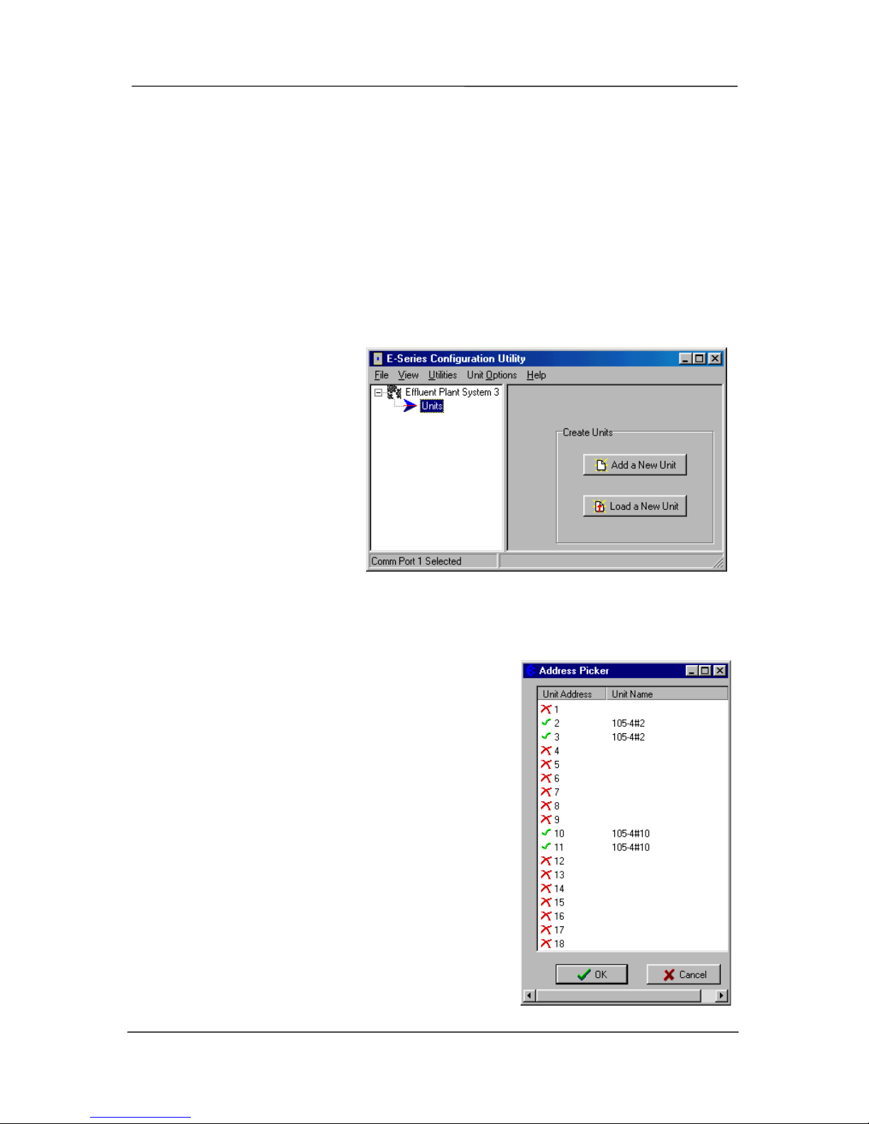
Chapter Four Configuration
man_105_2.9.doc Page 39
the modules in the system.
Password. You have the option of entering a password to protect the configuration files
against unauthorized changes. When you open a new project, you will be asked to enter a
password - if you do not enter any text - that is, press “ESC” or “Enter”, then password
protection is disabled. If you do enter a password, then you will need to enter this password
to make changes to the configuration or download or upload configuration. You only need to
enter the password each time you enter the project. Without the passowrd, you are able to
view the configuration details but you cannot make changes.
The password can be between 6 and 256 characters. You can also change password by
selecting this option from the “Utilities” menu.
If you are starting a new project, you have the option of “Enabling Security” - please read
Section 4.3.7 and the associated
warnings before using this option.
To proceed with the
configuration, double-click on
the project name on the menu on
the left side of the screen. “Units”
will appear. You can now enter
the types of units which will be
used in the system. If you doubleclick on “Units”, then the
modules that have already been
selected will appear.
Loading configuration from an existing module
To load the configuration from a module, connect the module to the PC via the RS232 cable
and click on “Load Unit”. This will allow you to view
the module configuration, change it, or copy it for
another module - refer to section 4.3.3 for more
information.
Adding a new module to the system configuration
To add a new module to the system configuration, click
on “Units” on the left-hand menu and then “Add Unit”.
Select the type of module from the list. The programme
will ask you to select the unit address. For 105U
modules, select an address between 1 and 95. For 105S
modules, select an address between 96 and 127.
The default name for a unit will include the unit address.
For example, “105-4#8” is a 105-4 module with unit
address 8 (and also 9, as a 105-4 takes two unit
addresses). You can change the name of a unit - for
example, you could replace the default name with
“Pump Station 14”.
Page 40
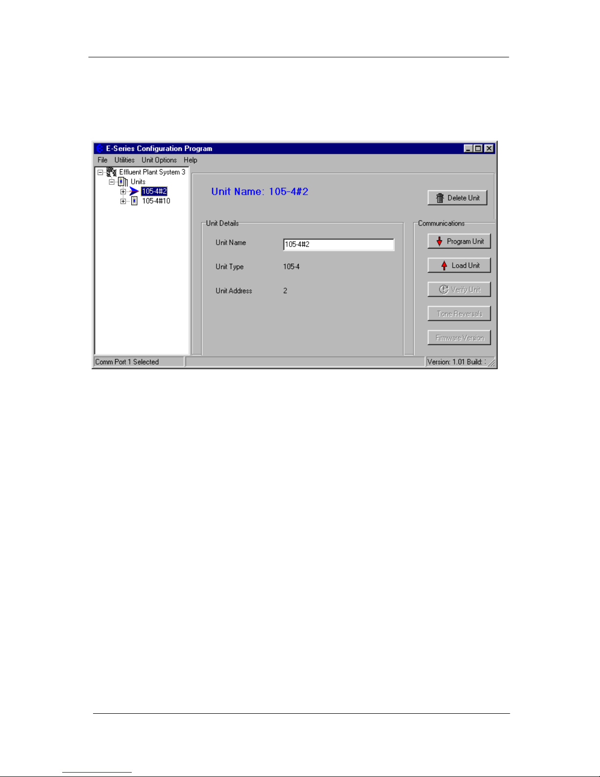
105 Radio/Serial Telemetry Module User Manual
Page 40 © January 2004
Deleting a Unit
A module can be deleted from the configuration by highlighting the unit and selecting “Delete
Unit”.
Page 41
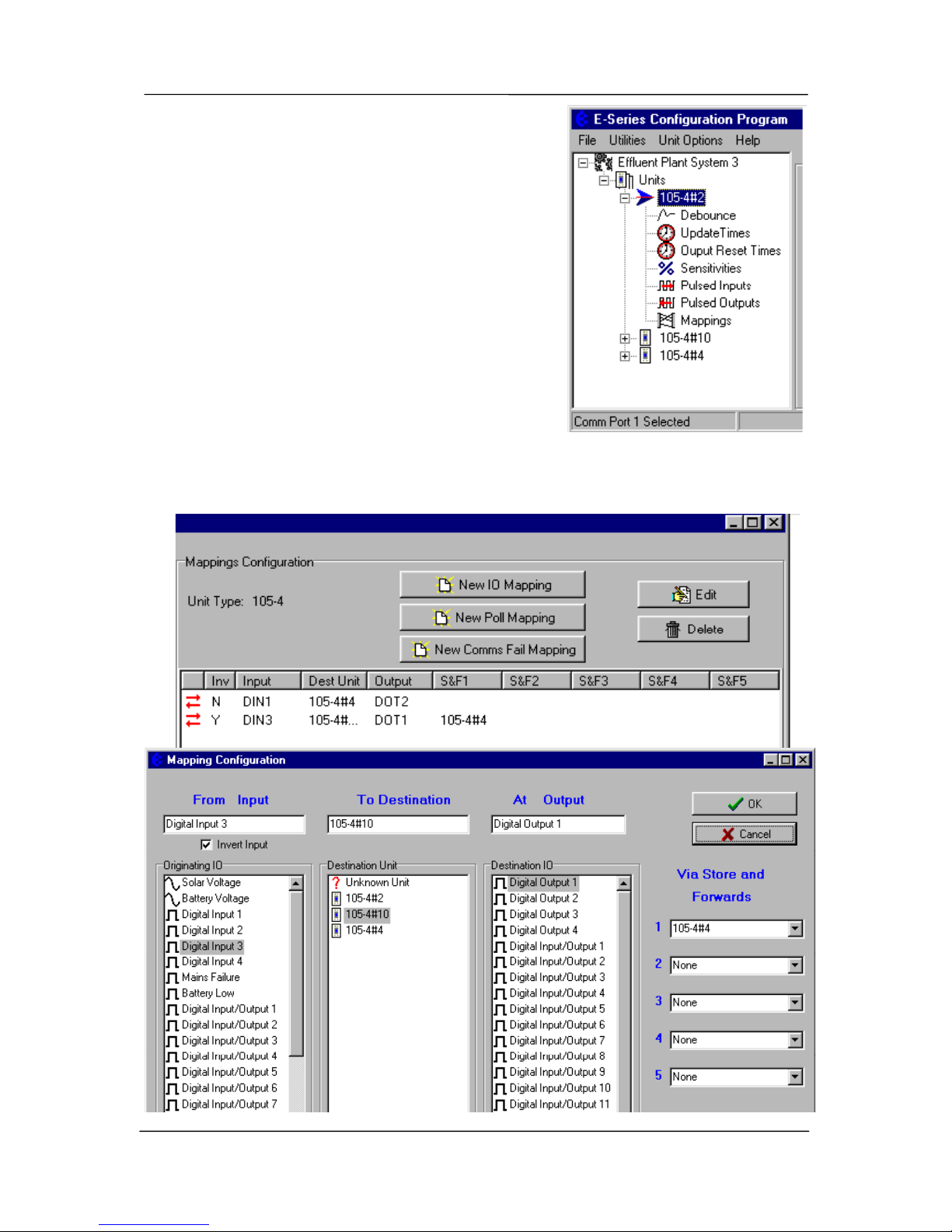
Chapter Four Configuration
man_105_2.9.doc Page 41
Configuring an individual module
Double-click on a unit shown on the left-hand menu.
The configuration options for each unit will appear. We
recommend that you configure I/O mappings first, and
then other options.
Select “Mappings” and the following screen appears.
There are three types of mappings:
• I/O mappings which link inputs to outputs
• Poll mappings, which enables a module on start-up
to request set its outputs quickly
" Comms Fail mappings, which maps communication
failure status to an output on the local module.
I/O Mapping To enter an I/O mapping, select “New I/O Mapping”.
Page 42
105 Radio/Serial Telemetry Module User Manual
Page 42 © January 2004
1. The I/O mapping display will show all inputs at the selected module - both physical
inputs and internal inputs. Select the input to be mapped.
2. If you wish to invert the mapping, select the “Invert Input” box. If you invert an input,
then the output will be the reverse of the input. Analogue I/O can also be reversed 0mA will be 24mA, 4mA will be 20mA etc. Do not invert pulse inputs.
3. The invert function is not available on 105-2 modules - only inverted digital inputs are
available (as internal inputs on the input list).
4. To select the destination module, you can either select the module from the “Destination
Unit” list, or enter the unit address in the “To Destination” box. You can enter an
address that has not yet been allocated to another unit.
5. You can select the output by entering the output number (1 – 255) in the “output” box, or
select an output from the displayed list. There will only be a list of possible outputs
displayed if at step 2 you selected a desrtination unit that has already been configured in
the system.
The output numbering for each module is:
105-1 105-2 105-3
First addr
(Even)
105-3
Second addr
(Odd)
105-4
First addr
(Even)
105-4
Second addr
(Odd)
Output 1 DO 1 DO 1 D/P O 1 AO 1 D/P O 1 DIO 5
Output 2 DO 2 None D/P O 2 AO 2 D/P O 2 DIO 6
Output 3 DO 3 None D/P O 3 AO 3 D/P O 3 DIO 7
Output 4 DO 4 None D/P O 4 AO 4 D/P O 4 DIO 8
Output 5 AO 1 None DO 5 AO 5 DIO 1 DIO 9
Output 6 AO 2 None DO 6 AO 6 DIO 2 DIO 10
Output 7 PO None DO 7 AO 7 DIO 3 DIO 11
Output 8 None None DO 8 AO 8 DIO 4 DIO 12
6. If you select a 105U-C or –G as the destination module, you will be asked to select a I/O
Register as the destination “output”. Note that the grey-shaded I/O registers have already
been allocated.
7. Select any intermediate repeater units needed to reach the destination address (entered in
order of nearest to furthermost repeater). You can either select from the list of configured
units or enter the unit address in the “Repeater” box. If no repeaters are required, do not
enter anything in the repeater boxes. If only one repeater address is required, enter the
address in box 1 and leave the other repeater boxes empty.
It is possible to configure multiple mappings for an input - each mapping will generate
separate transmissions. We recommend that you do not configure multiple mappings to the
same output as the output will have the value of the last message that it receives. Each output
should have only one mapped input.
Page 43
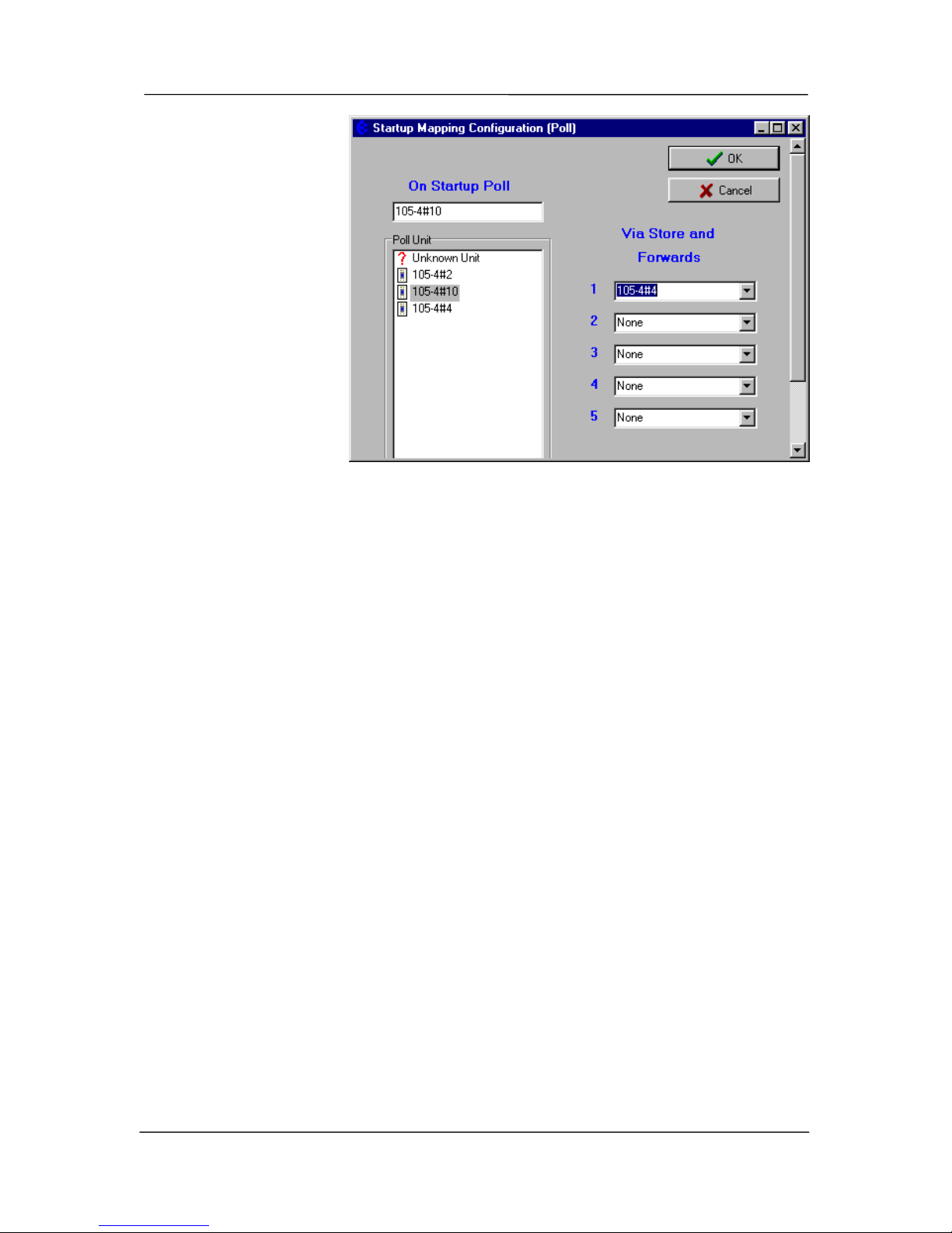
Chapter Four Configuration
man_105_2.9.doc Page 43
It is possible to map a
digital input to an
analogue output - the
output will be maximum
value when the input is
on and minimum value
when the input is off. It is
also possible to map a
analogue input to an
digital output - the
output will be on when
the input is equal or
greater than 12mA and
off when the input is less
than 12mA.
For more information
on using 105S modules,
refer to Section 4.3.8.
Edit existing mappings
To edit an existing mapping, double-click on the mapping line, or select the mapping line
and click “Edit”.
To delete an existing mapping
To delete a mapping, select the mapping and click “delete” or alternatively right-mouse
button click and select delete.
Configuring Start-Up Polls
When a unit is first turned on, its outputs will not be set until it receives update messages
from other units in the system. To ensure that outputs are set as soon as possible after start-up
the unit may be configured to “Poll” any other units with mappings to its outputs.
Select the remote unit to be polled from the unit list, or enter the unit address in the box. If
the remote unit communicates via repeaters, select the repeater units or enter the repeater
addresses.
Remember that if more than one remote unit is controlling the local outputs, then more than
one start-up poll should be configured.
Configuring Comms Fail Mappings
Each module has a “comms fail” status which may be mapped to a local output. The comms
fail status is active (on) if the module is transmitting a message and does not receive an
acknowledgement after five tries. By setting the comms fail status to a local output, you can
provide a communications alarm. The local output can be digital or analogue - if analogue,
the output will go to maximum value.
Page 44
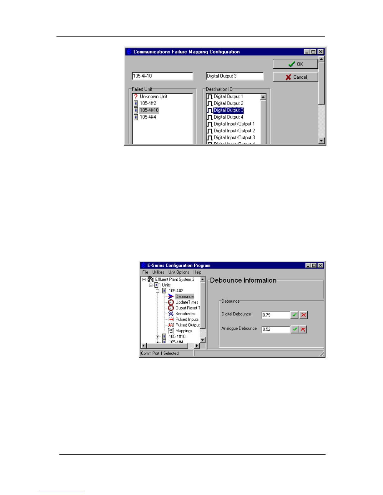
105 Radio/Serial Telemetry Module User Manual
Page 44 © January 2004
Although
communication
failure will activate
the output,
successful comms
does not reset the
output. You must
use the “Reset
outputs on comms
fail” option (Refer
to User Options
section).
Each remote module has a separate comms fail status - you enter a separate comms fail
mapping for different remote addresses. You can configure several comms fail mappings to
the same output - the output will be active if there is comms fail to any of the remote
addresses. You can also map a configure an output to activate upon any comms fail.
Configuring a “Comms Fail Address” of zero causes communication failure to any
destination module to be indicated on the selected output.
For example, if “Comms fail to unit 12” is configured to DO1, then the 105 module will set
(or activate) DO1 each time communications to unit 12 is not successful. If DO1 has a
“Reset output” time of 10 minutes configured for DO1, then DO1 will reset (de-activate) 10
minutes after the last comms fail to unit 12.
Debounce Configuration
Debounce is the time
which an input must stay
stable before the 105
module decides that a
change of state has
occurred. If a digital
input changes (say 0 →
1) and changes again (1
→ 0) in less than the
debounce time, then the
105 module will ignore
both changes. Debounce
may be configured for
digital inputs on the 105-1, 105-2 and 105-4 modules and the analogue inputs on the 105-2
module. The default value of 0.5 seconds is suitable for most applications. In applications
where a digital input may turn on and off several times slowly (for example, security
switches or float switches) a debounce time of up to 8 seconds may be configured. The
configured debounce time has no affect on pulse inputs.
Note that the analogue debounce is not configurable for the 105-1, but is configurable in the
105-2.
Page 45
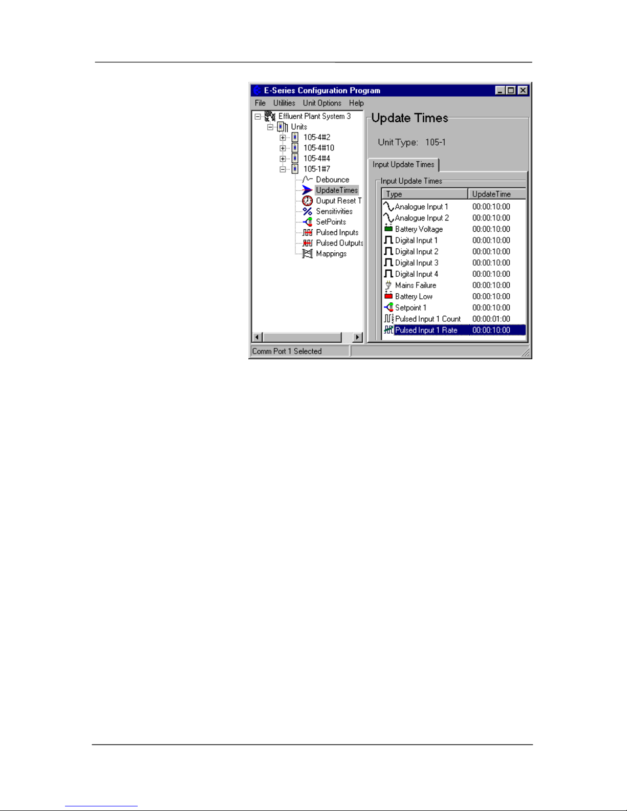
Chapter Four Configuration
man_105_2.9.doc Page 45
Update Time
Configuration
Update messages are sent if a
change message has not
occurred within the update
time period. The update time
may be set for each input both physical and internal
inputs.
The default period is 10
minutes for all inputs, except
for pulse inputs (1 minute).
Short update times should
only be used in special
circumstances. It is important
to remember the principle “Less radio traffic means
better communications”.
Frequent updates from
multiple units causes
congestion of the radio channel, which results in increased communication failures and poorer
performance of the system. To change an update time, select “Update Times” on the lefthand menu and double-click the selected input. The update time will be shown in
days:hours:minutes:seconds. Change the values in each field. The display also shows the
maximum and minimum values.
For the 105-1, -2 and –3 modules, the maximum update time is 16 minutes, however the
update time for 105-4 inputs can be up to 5 days. If a zero value is entered as an update time,
then the input will not update at all.
Changing Multiple Settings
You can change the Update Times of several inputs simultaneously by using the <Shift>
Select feature. For example, if you want to change all digital inputs to 1 minute update, you
could change each individually, or you could “block” the four digital inputs using the “Shift”
Select feature and select “Edit”. You only need to enter the change once to change all of the
inputs selected. This feature is also available with the other configurable parameters.
Output Reset Time Configuration
This allows the Comms Fail Time to be selected - this is the time for an output to reset if it
has not received an update or change message.
Each output on the unit, either analogue or digital, may be configured to reset (off or 0mA)
when no update transmission has been received for a certain time. This option can be used to
ensure that communications failure will not result in loss of control. For example, outputs
connected to pumps should be configured to reset on communications failure so that the
pump will turn off. The default condition is zero (no reset).
Page 46
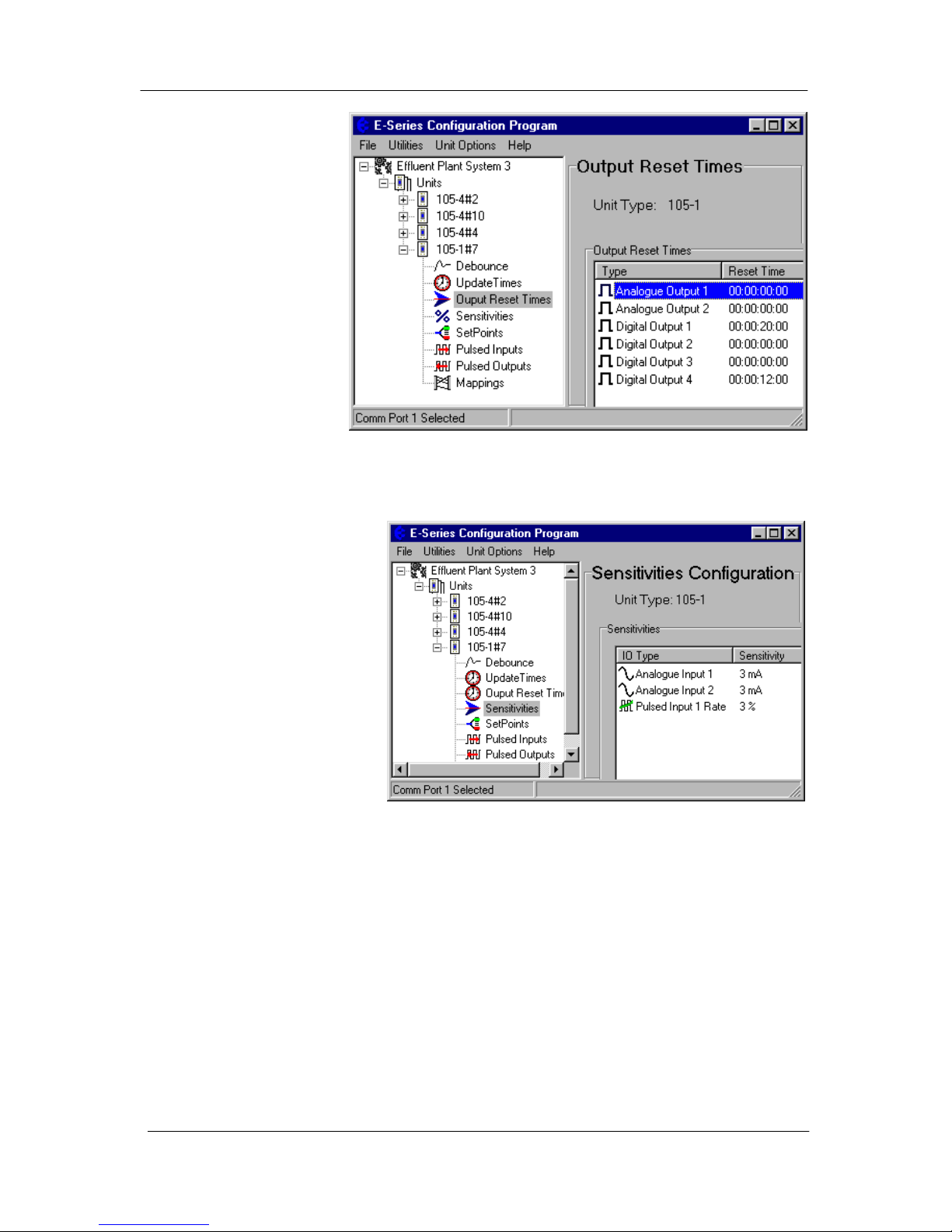
105 Radio/Serial Telemetry Module User Manual
Page 46 © January 2004
If the reset time is less
than the update time,
then the output will reset
when the reset time
expires, and then set
again when the update
message is received. We
recommend that the reset
time be a little more than
twice the update time.
To set an output reset
time, select “Output
Reset Times” on the lefthand menu and doubleclick the selected input.
The update time will be shown in days:hours:minutes:seconds. Change the values in each
field. The display also shows the maximum and minimum values.
Analogue Sensitivity Configuration
The analogue sensitivity is the
change required in an analogue
input before a “Change Of
State” is detected, and the new
analogue value is transmitted.
For input signals which vary
widely over a short period of
time or have a normal
oscillation, the analogue
sensitivity should be set to an
appropriately large value. This
ensures that many change
messages are not transmitted in
too short a time. This will
result in channel congestion, as
described in the preceding section.
To change an analogue sensitivity, select “Sensitivities” on the left-hand menu and doubleclick the selected input. The sensitivity for physical inputs is shown in mA and internal input
is shown as %.
SetPoint Configuration
Setpoints allow a remote digital output to be turned on and off depending on the value of an
analogue input. The “set-point status” internal input must be mapped to an output for this
option to have effect. When the AI is less than the Low Set-point (LSP), the set-point status
will be active (on, “1”) - when the AI is more than the High Set Point (HSP), the set-point
status will be reset (off, “0”). Note that the High Set Point (HSP) must always be higher than
the Low Set Point (LSP). For the 105-1 module, only AI1 has set-point values. For 105-2
modules, analogue inputs 1 - 4 have set-points.
Page 47
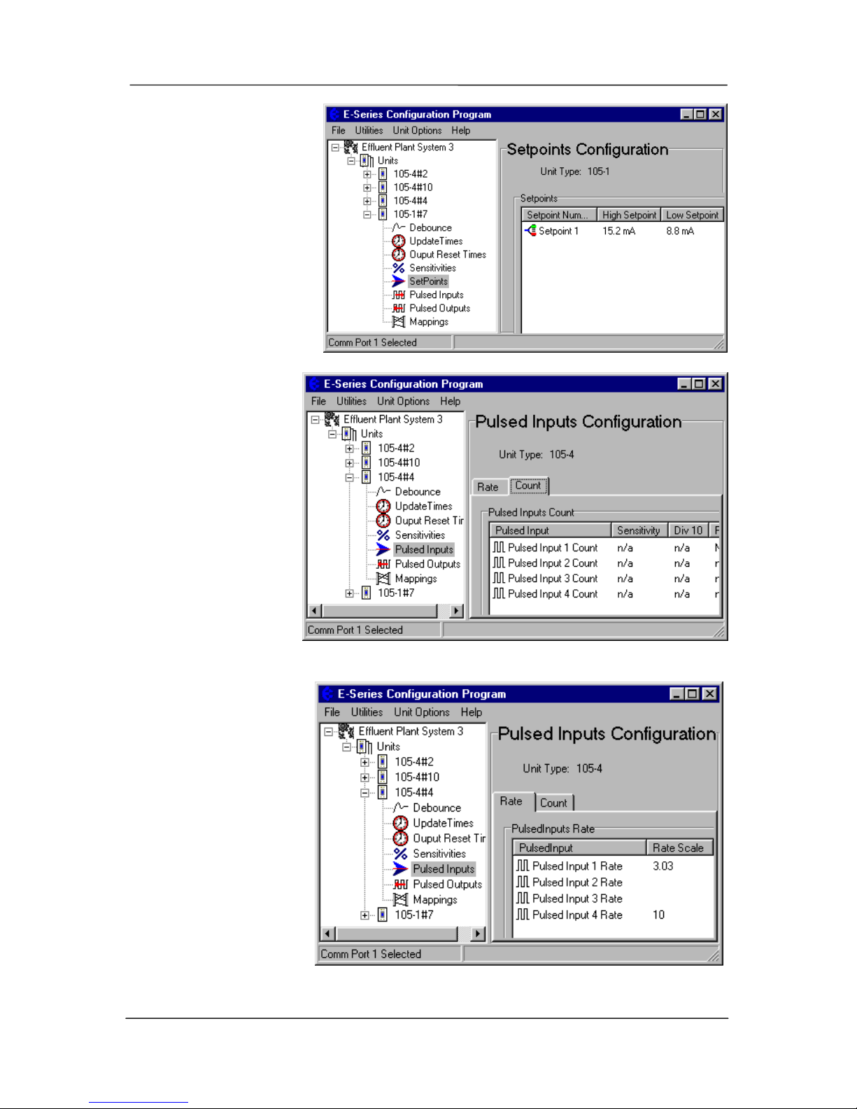
Chapter Four Configuration
man_105_2.9.doc Page 47
Debounce time operates
on the set-point status in
the same way as digital
inputs.
To change a setpoint
values, select “SetPoints”
on the left-hand menu and
double-click the selected
Setpoint Status.
Pulse Input Count
Configuration
PI1 of the 105-2 and 105-4
modules normally
count up to 100Hz (as
for the other PI’s),
however can be
configured to count up
to 1000Hz. This
configuration actually
divides the input count
by 10 - each count in
the PI1 register is then
equivalent to 10 input
pulses. If PI1 is
mapped to a PO, then
the maximum output
pulse rate is 100Hz,
however each output
pulse is equivalent to 10
input pulses.
To configure the “divide
by 10” feature, select
“Pulse Inputs” on the lefthand menu and select the
“Count” page - doubleclick “Pulse Input 1
Count” and enable
“divide by 10” counting.
Pulse Input Rate Scale
Configuration
When a pulse rate is
mapped to an analogue
output, the rate must be
scaled to the 4-20mA
output. The pulse rate scale is the rate (in Hz) corresponding to the maximum value (20 mA
Page 48
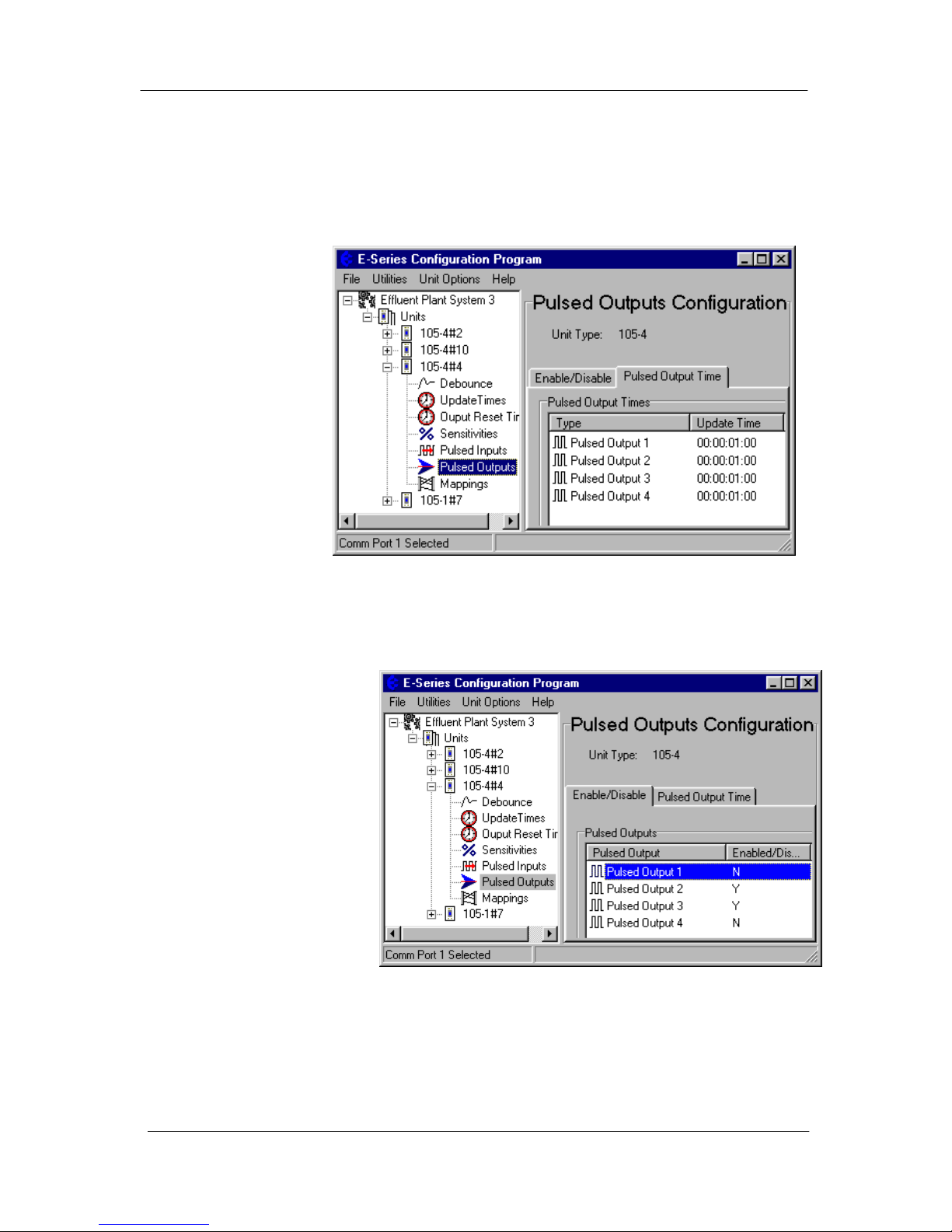
105 Radio/Serial Telemetry Module User Manual
Page 48 © January 2004
if mapped to an analogue output).
To configure the pulse rate scale, select “Pulse Inputs” on the left-hand menu and select the
“Rate” page - double-click the pulse input rate and enter the scale value.
Pulse Output Update Time Configuration
The pulse output
update time is the time
period over which
pulses are output after
a PI update is received.
It should be configured
to correspond to the
pulse input update time
for the corresponding
pulse input. This
ensures that the pulse
output rate matches as
closely as possible the
pulse input rate which
it is reflecting.
For example, if the P I
update time is 1 minute, then the PO update time should also be 1 minute. If the PI update
time is changed, then the PO update time at the remote module should be also changed. The
PO will still operate if the time is not changed, however pulses may be output faster or
slower than the input pulses.
To configure the pulse output
time, select “Pulse Outputs”
on the left-hand menu and
select the “Pulsed Output
Time” page - double-click
the pulse output and enter the
new time.
Pulse Output Enable
The PO’s for the 105-2 and
105-4 modules are also DO1-
4. To use as pulse outputs,
you need to enable them as
pulse outputs.
To enable pulse outputs, select “Pulse Outputs” on the left-hand menu and select the
“Enable/Disable” page - double-click the pulse output to enable.
Page 49
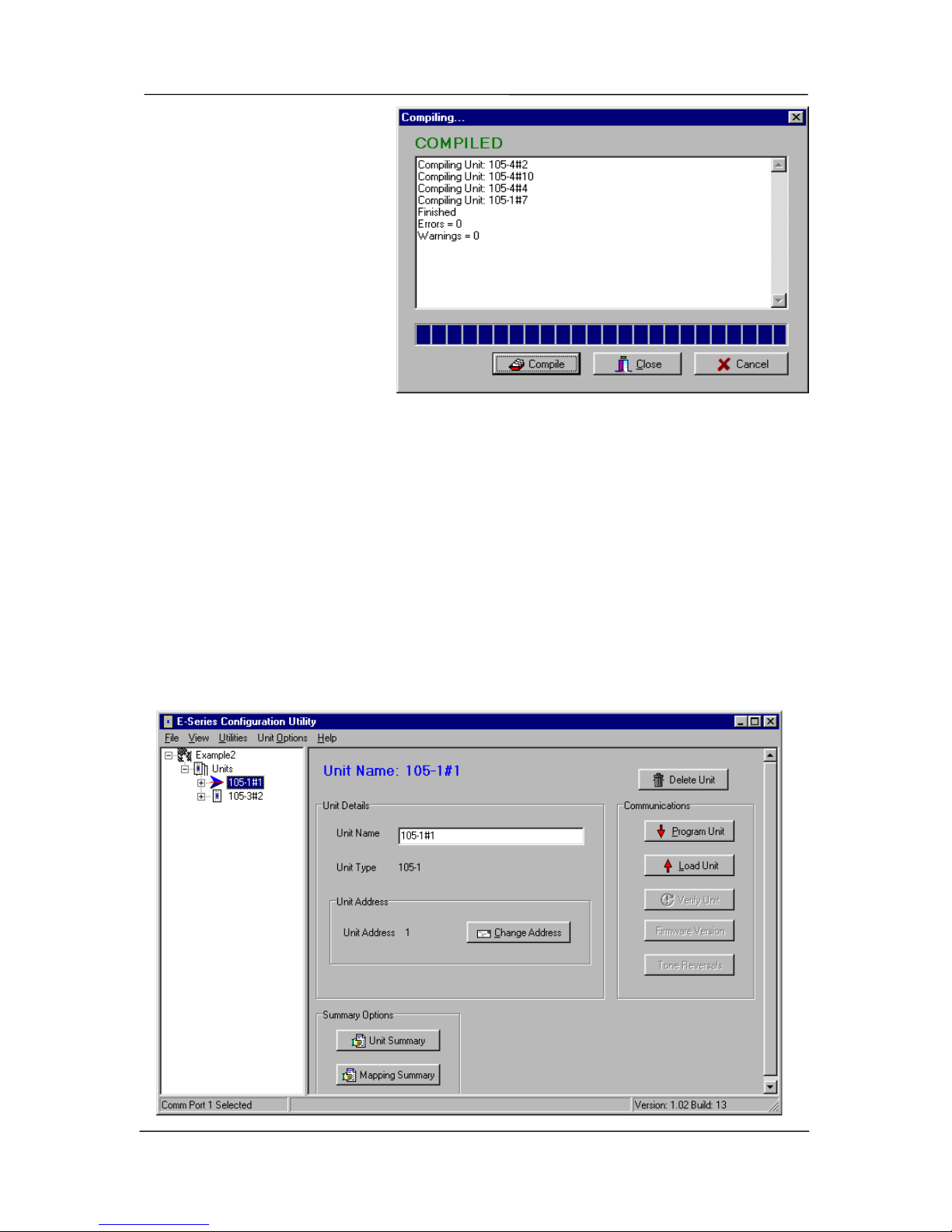
Chapter Four Configuration
man_105_2.9.doc Page 49
Compiling a System
When you have finished
configuring the modules, you
should compile the system. The
compile function scans the
configuration and reports any
detected errors. To compile the
system, select “Compile
System” from the “Utilities”
menu. Select the “Compile”
button. The system will
compile - the display will show
if there are any compile errors or
warnings.
4.3.3 Programming Configurations to Modules
To programme a module :
• Connect the cable from the PC’s serial port to the 105 serial port (see 2.4.10 for cable
connections)
• From the Utilities menu, select “Serial Port Setup”
• Select the appropriate serial port (COM1 - COM4)
• Select the unit to be configured from the left-hand menu
• Click on the “Program Unit” button.
Page 50

105 Radio/Serial Telemetry Module User Manual
Page 50 © January 2004
• You will be asked to confirm if the module already has a different system or unit address.
Each module will need to be programmed individually.
4.3.4 Loading Configuration from a Module
Care should be taken when loading a configuration from a module. It is easy to lose the
system address and unit address. We suggest that you first view the system address and unit
address - you can do this via the “Unit Options” menu. Note these addresses before loading
the configuration.
When you upload the configuration, the program will check if you want to load the addresses
from the module. If you do not, then the system address and unit address will change.
You are able to upload the configuration from a module into a new “project”, to view the
configuration and modify it. Note that as the “project” will not have the details of the other
modules in the system, the other modules and outputs will be shown as unit addresses and
output numbers. Don’t forget to download the configuration into the module after you
modify it.
If security has been enabled for the system, please read section 4.3.7.
If you are adding additional mappings to a 105U-C or 105U-G module, then you need to
change the archived configuration files first so you can download the modified configuration
details into the 105U-C or 105U-G
4.3.5 Modifying and Archiving Configuration Files
As you build a system configuration, it is automatically saved in the “Project” directory. We
recommend that all system additions and changes be made to the archived configuration files
first, and then downloaded to the module/s. This ensures that the archived files are always
maintained and accurate. If you modify the configuration of a module by uploading and then
downloading, then the module configuration will be different then the archived files.
If you lose the configuration files for a system, then you can rebuild the configuration by
uploading the configuration file from every module in the system.
4.3.6 Print Options
You can obtain a print-out of each module configuration. On each unit display, there are
“Unit Summary” and “Mapping Summary” windows. Each of these will display a printable
information page about that module. The Unit Summary page will display the user options
configured, and the Mapping Summary will display the mappings entered for that unit.
The printer may be selected from the Printer Setup option in the File menu.
4.3.7 Security
There are two security features available. You can enter a password to protect the
configuration files, and you can enable security encryption of the radio transmissions.
The password can be between 6 and 256 characters. The password is case sensitive and any
Page 51

Chapter Four Configuration
man_105_2.9.doc Page 51
ASCII characters can be used. If you have entered a password, then this password will need
to be entered if the configuration is to be changed later. You can view the configuration, but
you will not be able to make any changes. You are able to change the password from the
“Utilities” menu. If unauthorised access to the files is a concern, we recommend that you
change the password regularly or whenever there is a change of staff.
Security Encryption is an additional level of security. The security option uses an 8-character
security key to provide 64-bit data encryption of the radio messages. All modules in the same
system will be configured with the same security key used to encrypt and decrypt the
messages. This feature is available for modules with serial numbers with the middle three
numbers greater than 210 - that is xxxx210xxxx, or xxxx220xxxx etc. If you are adding
modules to an old system which does not have the security encryption feature, then you
cannot use security encryption on the new modules.
Note that the security key is different than the password.
• To enable the security encryption, select the “Enable Security” box on the project display.
An 8-character security key is entered and you will be prompted to enter the security code
a second time to confirm. The security key can be any characters or numbers. Characters
are case sensitive. The security key will never be displayed.
• If you do not enable security, there will be no data encryption of the radio messages.
This is the default setting.
• If a security key has been entered, this key is downloaded into each module as part of the
configuration download process. You can download another configuration at any time if the security key is different, or if there is no security key in the new configuration, the
old key will be over-written.
• You can change the security key in the configuration files simply by entering a new
security key in the security key window. You will be prompted to confirm the new
security key. If the configuration files are password-protected, you will be asked for the
password. Note that if you change the security key, it will not match the security key
previously loaded into existing modules.
• If you want to change a configuration, we recommend that you change the archived
configuration, and then download the configuration onto the module. The archived
configuration already has the valid security key.
• If you lose the archived configuration, you can upload the configuration from a module,
but you cannot upload a security key. That is, you can upload the module configuration,
view it, change it - but if you don’t know the original security key, the old key will be
over-written when you download the new configuration. This module will no longer
communicate with other modules in the system as the security key is different.
The security options provide security against a “hacker” in the following way:
#
A hacker cannot listen-in to radio messages without the security key to decrypt the radio
messages. Similarly, a hacker cannot force outputs by transmitting a radio message to a
module without the security key.
#
A hacker cannot access the security key from an installed module or from the
configuration files.
Page 52

105 Radio/Serial Telemetry Module User Manual
Page 52 © January 2004
#
The archived configuration files cannot be changed, downloaded or uploaded without the
password.
Warning!!
These security options provide a high level of secu rity, but no data-security system can
provide “100% protection”. But it does make it very difficult for someone to interfere
with the 905U system - difficult to the point where there would be many easier alternate
ways to cause malicious damage.
The password must be kept in a secu re place. Security procedures need to be adopted.
If staff with access to the password leave your organisation, we recommend that the
password be changed.
We recommend that you use a random 8-character string for the securi ty key and that
you do not record the key. It is not necessary to k n ow w hat th e secu rity k ey is. T he k ey
will be recorded in the archived configuration files, and therefore the configuration
files should be held in a secure place and backed up.
The security key does not prevent a hack er uploading a configuration from a modu le
and downloading with a new security key. This module will no longer operate with
other modules in the system. To prevent this, unauth orised access to modules must be
prevented.
If you lose the configuration files, you can regenerate these by uploading the configuration
from every module in the system into a new project with a new security key. After uploading
each module, download the configuration with the new security key.
If you wish to change the security key, simply enter a new key in the configuration program,
and download the new configuration to all modules in the system.
4.3.8 Using 105S Modules
105S modules can be used by themselves, as “line telemetry” or “wired I/O”, or they can be
used as I/O expansion for 105U modules. As the 105S modules are connected by RS485, the
105S modules can be separated from the 105U modules by some distance. There can be up to
32 addresses on the one RS485 multi-drop link. Note that each –3 and –4 module takes up 2
addresses. For example, you could have up to 32 modules sharing a multi-drop link if they
are all –1 or -2 modules - if they are all –3 or –4, then you could only have 16 modules on
the link.
105S modules are configured with unit addresses in the range 96 – 127.
Page 53
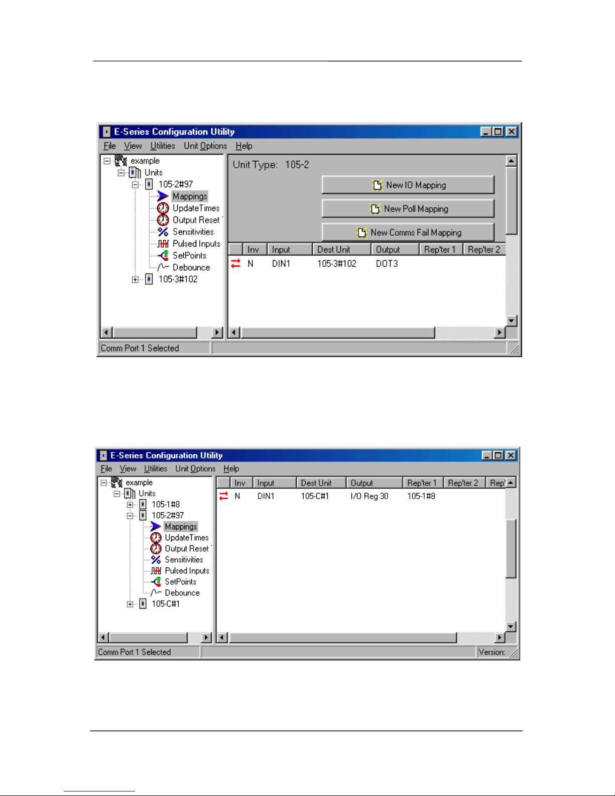
Chapter Four Configuration
man_105_2.9.doc Page 53
Example 1 - Mapping to another 105S module on the same link.
The I/O mapping is done in the same way as for 105U modules.
Example 2 - Mapping to a remote 105U.
In this example, a 105S-2 is connected to 105U-1#8. DI1 is mapped to a remote 105U-C
module. The 105U that is connected to the 105S module acts as a repeater - a serial-to-radio
repeater.
When DI1 changes, the 105S will send a message via the serial link to 105U-1#8, and this
105U module will repeat the message by radio to the 105U-C module.
Page 54
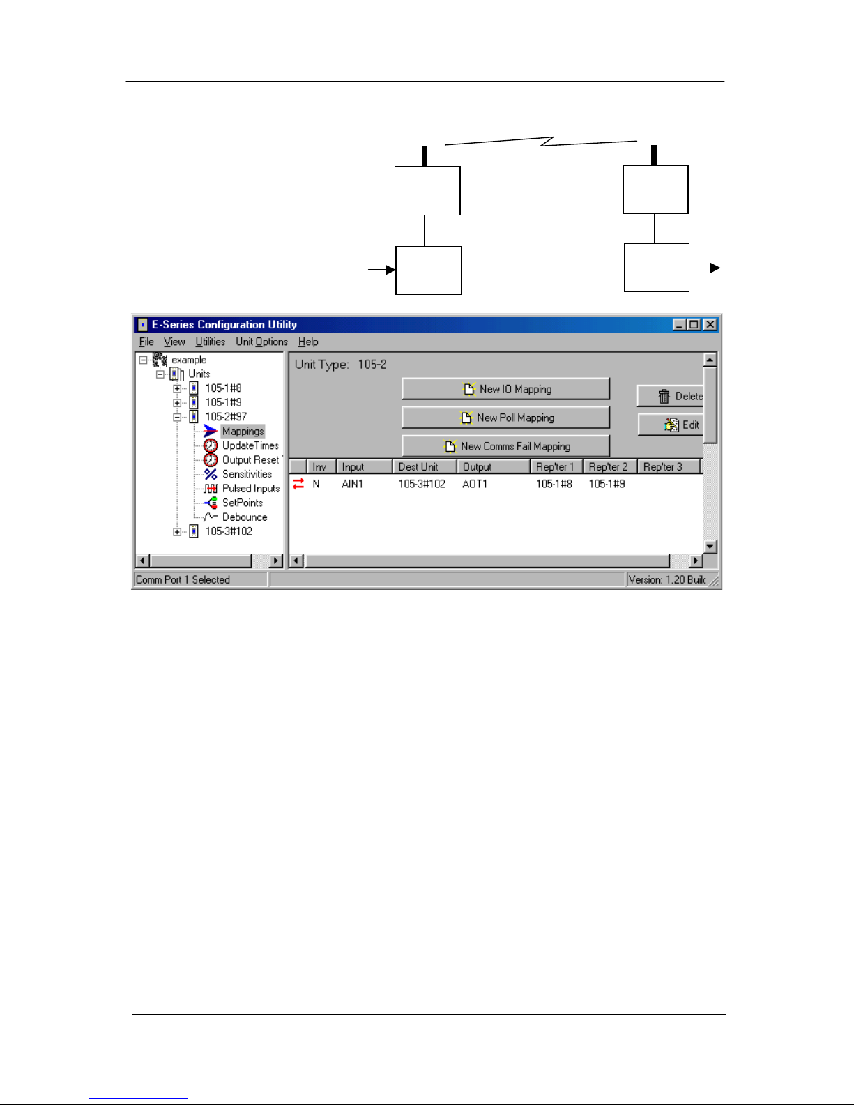
105 Radio/Serial Telemetry Module User Manual
Page 54 © January 2004
Example 3 - Mapping to another 105S which is connected to a different 105U
In this example, both 105U
modules act as repeaters.
The first is a “serial-toradio” repeater and the
second is a “radio-to-serial”
repeater.
105S-2
#97
105U-1
#8
105U-1
#9
105S-3
#102
AI1
AO1
Page 55

Chapter Five Specifications
man_105_2.9.doc Page 55
Chapter Five SPECIFICATIONS
General
EMC approval EN55022 (CISPR 22)
- CLASS B
EN 50082-1
ETS 300 683
AS 3548
IEC60950
89/336/EEC
Radio standards
105U only
MPT 1329 UK
EN-300-220
AS 4268.2 AUST
RFS29 NZ
458 MHz, 500 mW EIRP
430 - 450 MHz, 10 - 500 mW
869 MHz, 500mW
472 MHz, 100 mW EIRP
458 MHz, 500 mW EIRP
Housing 130 x 185 x 60mm
DIN rail mount
Powder-coated, extruded aluminium
Terminal blocks Removable Suitable for 2.5 mm2 conductors
LED indication Power supply,
OK operation, digital I/O,
RX and TX
Operating Temperature -20 to 60 degrees C
Power Supply
Battery supply 11.3 - 15.0 VDC
AC supply 12 - 24 VAC, 50/60 Hz Overvoltage protected
DC supply 15 - 30 VDC Overvoltage and reverse voltage
protected
Mains supply 110-250 VAC via plug-pack transformer
Battery Charging circuit Included for 1.2-12 AHr sealed lead acid
battery
Solar regulator Included Direct connection of solar panel (up
to 30W) and solar battery (100 AHr)
Current Drain 70 mA quiescent for ‘U’
45 mA quiescent for ‘S’
+ 10 mA/active digital input
+ 25 mA/active digital output
+ 2 x analogue I/O loop (mA)
Radio transmitter inrush 400mA @ 13.8VDC
250mA @ 24VDC
500mW RF power
Analogue loop supply Included, except 105-4 24V DC 150 mA
Mains fail status Monitored Can be transmitted to remote
modules
Battery voltage Monitored As above
Page 56

105 Radio/Serial Telemetry Module User Manual
Page 56 © January 2004
Radio Transceiver (105U)
Single channel synthesised Direct frequency modulation
Frequency 405 - 490 MHz
220 – 235MHz
869.4 – 869.65 MHz
12.5 kHz, 10 - 500 mW
25 kHz, 4W
250KHz, 500mW
Spurious emissions RX - <-57 dBm
TX - <-37 dBm
Frequency Stability +/- 1.0 kHz
Receiver Sensitivity 0.4uV at 12dB SINAD
Signal detect / RSSI -120 to -80 dBm
Expected line-of-sight range
400 – 500MHz
2 km @ 10mW EIRP
5 km @ 100mW EIRP
10 km @ 500 mW EIRP
Expected line-of-sight range
220 MHz
25 km @ 4W EIRP
40 km @ 10W EIRP
Expected line-of-sight range
869 MHz
5 km @ 500mW EIRP
Range may be extended by up to 5
intermediate modules as repeaters
Antenna Connector Female coaxial Protected by gas discharge surge
arrester (but not the 869MHz
model).
Serial Ports
RS232 Port DB9 female DCE 9600 baud, no parity, 8 data bits, 1
stop bit
RS485 Port 2 pin terminal block 9600 baud, no parity, 8 data bits, 1
stop bit,
Typical distance 1km
Data transmission On change-of-state
+ integrity update
Update time configurable
Protocol - serial
- radio
asynchronous ARQ, with
16 bit CRC
synchronous ARQ
Automatic acknowledgements with
up to 4 retries
Communications fail status May be mapped to local or
remote output
Resetting of outputs on comms fail
configurable
Page 57

Chapter Five Specifications
man_105_2.9.doc Page 57
Inputs and Outputs
Digital Inputs 105-1 Four
105-2 Four
105-3 None
105-4 Four plus 12
selectable I/O
Opto-isolated (5000V)inputs,
suitable for voltage free contacts or
NPN transistor, contact wetting
current 5mA, input debounce 0.5
second
As above, but with 3000V surge
protection instead of opto-isolation
Digital Outputs 105-1 Four Relay output contacts, normally
open, AC1 2A 50V
DC3 2A 30V, 5A 20V
Digital Outputs 105-2 One
105-3 Eight
105-4 Four plus 12
selectable I/O
FET output, 30 VDC 500mA max.
Pulse Inputs 105-1 One
105-2 Four
105-3 None
105-4 Four
Uses DI1. Max rate 100Hz, min.
off-time 5msec.
Uses DI1-4. Max rate of DI1 is
1000Hz, min. off-time 0.5msec
Max rate of DI2-4 is 100Hz, min.
off-time 5msec.
Pulse Output 105-1 One
105-2 None
105-3 Four
105-4 Four
FET output, 30 VDC 500mA max
Max rate for 105-1 is100 Hz. Max
rate for 105-3 is 1000 Hz. Pulse
signal recreated, pulse rate avail. on
analogue output, (scaling
configurable).
Divide-by-10 available for 1000Hz
inputs.
Analogue Inputs “floating” differential
input, common mode
voltage -0.5V to 27V
105-1 Two 4-20 mA
105-2 Six 0-20mA
105-3, -4 None
24 VDC for powering external loops
provided, 150 mA max, Digital
filter time constant 1 second.
Resolution 15 bit, Accuracy 0.1%
Resolution 12 bit, Accuracy 0.1%
Analogue Input Setpoints 105-1 AI 1 only
105-2 AI 1-4
Configurable high & low set-points,
allowing set/reset of remote digital
outputs
Page 58

105 Radio/Serial Telemetry Module User Manual
Page 58 © January 2004
Analogue Outputs current sink to common
105-1 Two 4-20mA
105-2, -4 None
105-3 Eight 0-20mA
max loop voltage 27V,
Resolution 15 bit, Accuracy 0.1%
Resolution 15 bit, Accuracy 0.1%
System Parameters
Network Configurations Communications via radio
or RS485 or network of
both
Up to 95 radio units with up to 32
serial units off each radio unit
Mapping Any input to any output in
system
User Configuration RS232, PC or laptop
Diagnostics
On board diagnostics Automatic check on start-
up
Via RS232 terminal or
laptop
Input status
Output test
Incoming radio signal level
Simple radio path testing
Page 59
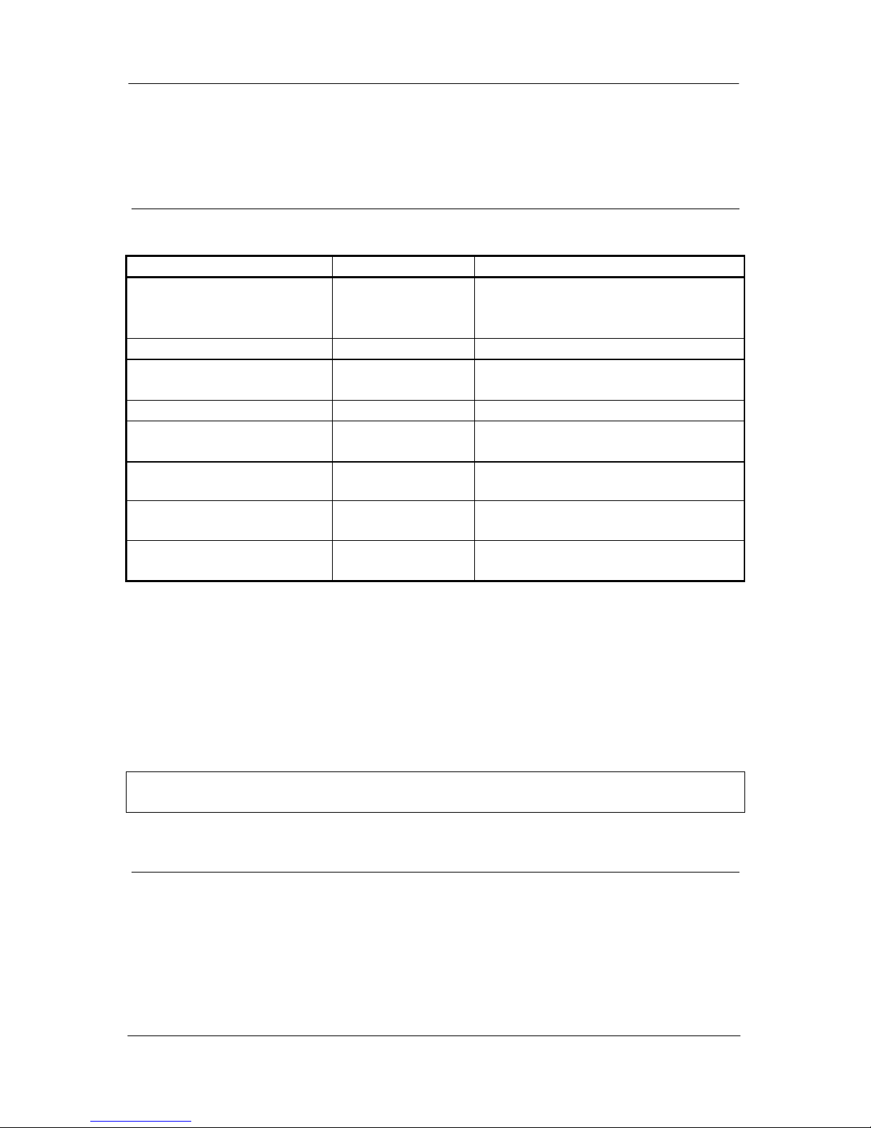
Chapter Six Troubleshooting
man_105_2.9.doc Page 59
Chapter Six TROUBLESHOOTING
6.1 Diagnostics Chart
INDICATOR CONDITION MEANING
OK LED OFF Continuously
• Battery Voltage low
• CPU failure
• +24V supply failure/overload
OK LED ON Continuously
• Normal Operation
PWR LED ON Continuously
• Supply available from SUP1/SUP2
• Supply available from solar panel
TX LED ON Flashes briefly
• Radio transmitting
RX LED ON Flashes briefly
• Radio Receiving
• Serial port communicating
RX LED ON Flashes
continuously
• Module in Configuration Mode
RX LED ON Continuously
• Test Button press in Configuration
Mode
No transmission on change of
state
• Unit not configured correctly - re-
configure and check operation
The green OK LED on the front panel indicates correct operation of the unit. This LED
extinguishes on failure as described above. When the OK LED extinguishes shutdown state is
indicated. In this state, all digital outputs turn OFF and the +24V supply turns off.
On processor failure, or on failure during start-up diagnostics, the unit shuts down, and remains
in shutdown until the fault is rectified. The unit also shuts down if the battery voltage falls
below 10.8 volts. This is a protection feature designed to protect the battery from deep discharge
in case of extended period without supply voltage.
Note: During diagnostic testing, it is likely that the module will reset and restart. This will
affect the output signals.
6.2 Self Test Functions
6.2.1 Input to Output Reflection (105-1 only)
The unit will require re-configuration after SELF TEST. Ensure you know the
required operational configuration including system and unit addresses so that the
network can be restored after testing.
Remove the cover in the front panel, and set the DIP switches as shown below. Hold down the
Page 60

105 Radio/Serial Telemetry Module User Manual
Page 60 © January 2004
red button for five seconds, or until the Rx LED glows yellow, release the Red button (the Rx
LED now flashes), then press and release the Red button (the flashing Rx LED extinguishes).
0 0 0 0 0 0 0 0
1 0 0 0 0 0 0 0
Input signals may now be connected to the input terminals of the module. If the module is
operating correctly, then the input signals will be reflected to the corresponding output on the
same module. For example, if DI 1 is connected to common - i.e. the first digital input is
turned "ON" - then DO 1 will activate, if the module is functional. Similarly, if a 12mA
signal is connected to AI 2, then a 12mA signal should be able to be measured from AO 2, if
the module is functioning correctly.
If a module does not pass its self test function, then it should be returned to an authorised
service agent for attention
6.2.2 Radio Testing using Tone Reversals
This function allows the unit to be configured to continuously transmit a sequence of alternate
zeros and ones on the radio. This function provides the facility to check VSWR of antennas
during installation, as well as checking the fade margin of the path between two units (see
below - received signal strength indication).
The tone reversals function is initiated by setting all of the DIL switches to ON, and holding
down the red button for approximately 5 seconds( until the RX LED lights continuously). On
releasing the button, the RX LED will flash continuously, and the TX LED will light,
indicating that the radio transmitter is on.
To finish the test, push the red button again or re-power the module.
6.2.3 Diagnostics functions
To aid in the checking and set-up of the 105 unit, a user friendly menu provides access to
diagnostic functions in the 105. Use of the diagnostics menu does not affect module
configuration.
The diagnostics functions can be accessed from the E Series Config software - the same
software package used to configure the modules. Connect the laptop or PC to the module
using a configuration RS232 cable.
Either open the archived project containing the module, or start a New Project and select
“Load a New Unit” - select the correct type of module. After the unit has loaded, select the
Diagnostics box.
Page 61
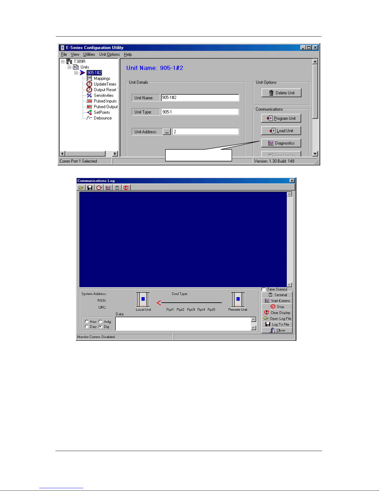
Chapter Six Troubleshooting
man_105_2.9.doc Page 61
A “Terminal” screen will appear. Select the “Terminal” box.
Connect the module (ensure the RS485 port is disconnected first) to the PC using the same
serial cable used for configuration.
The diagnostics menu is accessed by removing the blue “plug” from the front of the module
and setting all switches to ‘0’ or “Open”, and holding down the red button for approximately
5 seconds, until the RX LED lights continuously. One of the following menus will be
displayed on the terminal :
Select for Diagnostics
Page 62

105 Radio/Serial Telemetry Module User Manual
Page 62 © January 2004
105 V1.0
a) Ins
b) Tones
c) Comms
d) DO1
e) DO2
f) DO3
g) DO4
h) AO1
i) AO2
j) Switch
k) Signal
>
1052 V1.0
a) Digital Ins
b) Analog Ins
c) Tones
d) Comms
e) DO1
f) Switch
g) Signal
>
1053 V1.0
a) Ins
b) Tones
c) Comms
d) DO1
e) DO2
f) DO3
g) DO4
h) DO5
i) DO6
j) DO7
k) DO8
l) AO1
m) AO2
n) AO3
o) AO4
p) AO5
q) AO6
r) AO7
s) AO8
t) Switch
u) Signal
>
1054 V1.0
a) D Ins
b) A Ins
c) Tones
d) Comms
e) DO1
f) DO2
g) DO3
h) DO4
i) DIO1
j) DIO2
k) DIO3
l) DIO4
m) DIO5
n) DIO6
o) DIO7
p) DIO8
q) DIO9
r) DIO10
s) DIO11
t) DIO12
u) Signal
>
Choose an item from the menu by entering the letter before that item. For example, to select
the "Signal" function from the 105-2 Menu, enter :- k
During the diagnostics session, if you press Enter or Space while the menu is displayed, the
module will restart in normal operating mode. To re-enter diagnostics mode, hold the red
button for 5 seconds etc.
After the diagnostics session is over, force the module to restart, then select “Stop
Terminal”, then “Close”.
Inputs
This option provides a dynamic display of the status of all of the inputs in the 105, both
internal and external.
105-1 Modules
1234MLS P CNT AI1 AI2 P RATE VBATT
0101001 00F6 C000 4000 8000 9C00
The first 7 values (1234MLS) each represent a single digital input. A ‘1’ indicates that that
input is ON, and a ‘0’ indicates that the corresponding input is OFF. "1234" represents the
four physical digital inputs, DI1 to DI4. "M" is the mains fail status (‘1’ for mains fail, ‘0’ for
mains OK). "L" is the battery low volts status (‘1’ for low volts ‘0’ for OK). "S" is the setpoint status.
Page 63
Chapter Six Troubleshooting
man_105_2.9.doc Page 63
P CNT, AI1, AI2, P RATE, and VBATT each represent 16 bit values, displayed as four
hexadecimal digits.
P CNT is the current value of the pulsed input counter. This value should increment each time
‘DI 1’ turns from OFF to ON. P RATE displays the current pulse rate at DI1. This value is
scaled according to the MAXRATE value configured (0 Hertz is displayed as 4000, and the
maximum rate is displayed as C000).
AI1 and AI2 represent the value for the two analogue inputs. Full scale input (20 mA) is
displayed as C000, 4mA is displayed as 4000, and 0ma is displayed as 2000. Analogue
inputs are filtered digitally with a time constant of 1 second, so a sudden change in the
analogue input current will result in a slower change in displayed analogue value, finally
settling at the new value.
A guide to translate the displayed value to the analogue input current is provided below.
Add together the figures corresponding to each digit in each position to
determine the current (mA)
e.g. displayed value 3456 = 2.000+0.500+0.039+0.003
= 2.542mA
Digit Leftmost position Next position Next position Rightmost
position
0 - 0.000 0.000 0.000
1 - 0.125 0.008 0.000
2 0.000 0.250 0.016 0.001
3 2.000 0.375 0.023 0.001
4 4.000 0.500 0.031 0.002
5 6.000 0.625 0.039 0.002
6 8.000 0.750 0.047 0.003
7 10.000 0.875 0.055 0.003
8 12.000 1.000 0.063 0.004
9 14.000 1.125 0.070 0.004
A 16.000 1.250 0.078 0.005
B 18.000 1.375 0.086 0.005
C 20 1.500 0.094 0.006
D 22 1.625 0.102 0.006
E - 1.750 0.109 0.007
F - 1.875 0.117 0.007
VBATT is the current internally derived battery voltage. 4000 corresponds to 8 Volts, C000
represents 16 volts. A quicker method is use the calculation :
Battery voltage (volts) = ½ I + 6, where I is the mA value determined from the above table
using VBATT. For example, a value of VBATT of A000 gives an I value of 16mA from the
above table. The battery voltage corresponding to this is 14V (or ½ x 16 + 6).
Page 64

105 Radio/Serial Telemetry Module User Manual
Page 64 © January 2004
105-2 Modules
Digital Inputs
DIN SETPNT PULSED
1234MSL123456 PIN1 PIN2 PIN3 PIN4
0000100111111 0000 0000 0000 0000
Analogue Inputs
VBAT PR1 PR2 PR3 PR4 AI1 AI2 AI3 AI4 AI5 AI6
8138 4000 4000 4000 4000 0D3A 0CD2 0CC7 0CC7 0CD4 0CC7
105-3 Modules
ML VBAT VSLR
00 9FA2 0000
105-4 Modules
Digital Inputs
DIN DIO PULSED
1234 123456789ABC MLS PIN1 PIN2 PIN3 PIN4
1001 010101010 001 101 0001 0001 0001 0001
Analogue Inputs
VBAT PR1 PR2 PR3 PR4
8DBE 0000 0000 0000 0000
Tones
This provides the same function as described above in 6.2.2. Tone Reversals. This function
may be used to check VSWR of antennas, and may be used in conjunction with the Signal
option (described below) to check the path between two 105 units.
Comms
This function allows monitoring of all messages transmitted and received over the radio. A
better comms display function is available using the “Comms Logging” feature in the
configuration software - refer to section 6.2.4.
Transmitted messages are displayed starting in the leftmost column of the display. Received
messages are displayed indented by one space. Received messages which have been corrupted
are displayed with a '*' in the first column of the display. The first four hexadecimal digits are
the system address attached to the message, and must match for units to communicate
Page 65

Chapter Six Troubleshooting
man_105_2.9.doc Page 65
successfully.
Example (105-1):
>c
Comms
01FA8106008005C6727D44
Command message transmitted by this unit.
*01FA8186C6E0E3 Corrupt Acknowledge received from remote.
01FA8106008005C6727D44 Message re-transmitted by this unit. (no Ack)
01FA818600E0E3 Valid Acknowledge received from remote.
*01FB860100800100009286 Corrupt message received from remote unit.
01FA860100800100009286 Re-sent message received from remote unit.
01FA868100FCE4 Acknowledge message from this unit to remote.
DO1 to DO8, DIO1 to DIO12
These options allow the user to set and clear digital outputs. To set an output, select the
corresponding menu item, at the prompt, type the value FFFF to turn the output ON, or 0000
to turn the output OFF. For example, to set DO1 ON,
>e
DO1
>FFFF
AO1 to AO8
These options allow the user to set analogue outputs to any value. To set the output, select the
corresponding menu item. At the prompt type the value required for the analogue output as a
four digit hexadecimal value. Refer to the table above for analogue current/expected value
relationship. To set AO2 on 105-3 to 19 mA :
>m
AO2
>B800
Switch
This option allows testing of the DIL (Dual In Line) switches. The diagram below indicates
the layout of the switches of which there are two sets of eight, with an “Enter” button located
to the right of the pair. the display indicates the current switch settings with the digit ‘1’
corresponding to ‘On’ and the digit ‘O’ corresponding to ‘Off’. Changing the switch settings
in this mode will change the display. Test each switch and check to ensure the display
changes accordingly.
Switches
Displayed
1110001001010101
1 1 1 0 0 0 1 0
0 1 0 1 0 1 0 1
Page 66

105 Radio/Serial Telemetry Module User Manual
Page 66 © January 2004
Signal
This option provides for testing the radio path between two 105-U units for a suitable fade
margin. Although a pair of units may communicate successfully, radio communication may
be affected by a range of influences, including atmospheric conditions, changing landscape,
degradation of antennas or co-axial cable, low battery voltage etc. Fade margin is an
indication of how far a radio path can deteriorate before communication becomes unreliable.
When using the Signal feature, a meter is displayed with a mark indicating the current
received radio signal level. To check the radio path between two units, select the signal option
at the local unit. The remote unit may then be set up for tone reversals (refer 1 above) and the
signal level read from the meter.
A simpler method when remote units are not easily accessible is to cause a transmission from
the local unit to the remote unit (by setting a digital input which maps to the remote unit, for
example). The meter will latch the received signal from the remote unit for half a second,
allowing the received level to be read.
Under normal radio conditions, a reading of 0 indicates a very marginal communication path.
For reliable communications, the signal reading should be 3 or above.
>k Minimum signal level for reliable comms
Signal
0123456789----
#
In areas experiencing radio interference or high background noise, reliable communications
may not be achievable even with this signal level. To determine if interference is occurring
the signal option may be selected without any other 105 units active. In a normal radio
environment, no reading should be displayed. If a reading is displayed, then the received
signal strength from the remote should be at least three counts higher than the
background noise for reliable communication.
>k Displayed signal level of
Signal background noise/interference
0123456789----
#
>k Minimum signal level for reliable comms
Signal
0123456789----
#
When using directional antennas (i.e. YAGI antennas) this feature may be used to peak the
received signal level. Set-up the remote unit to transmit tone reversals as described above,
and observe the signal indication while adjusting the orientation of the antenna. A peak in
signal level indicates optimum orientation of the antenna.
Page 67
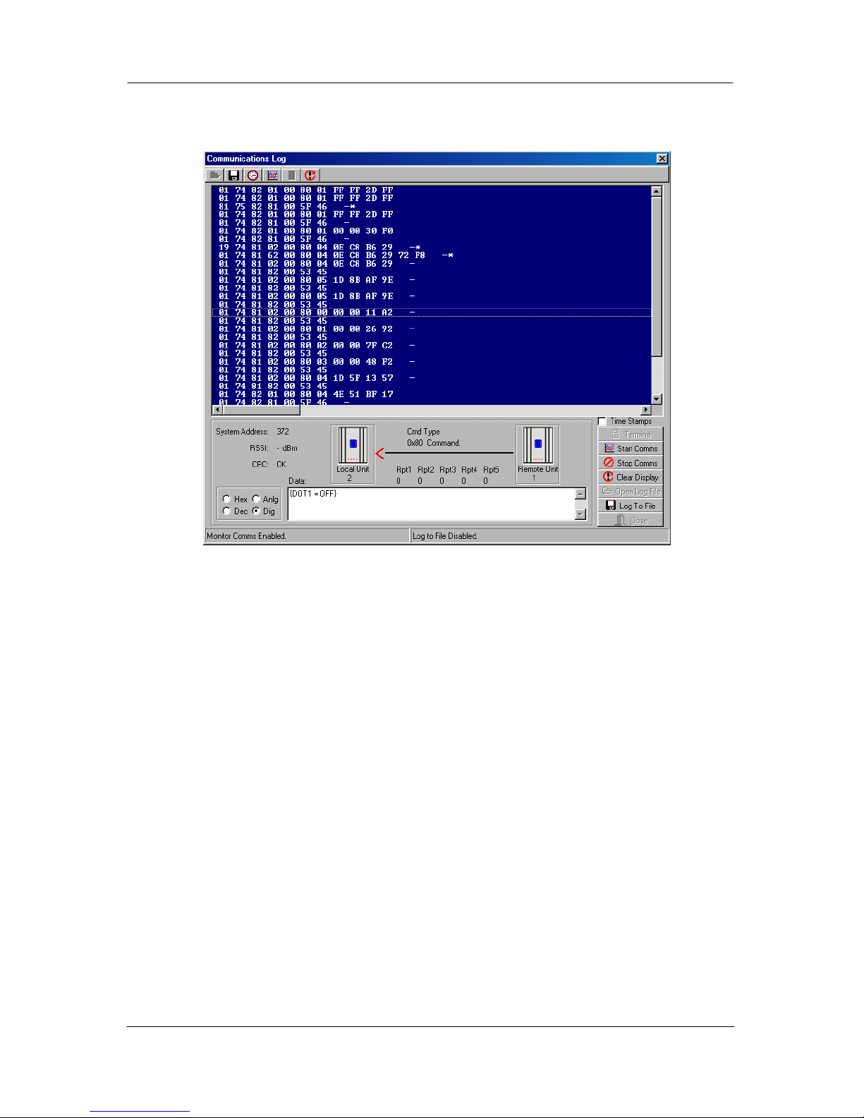
Chapter Six Troubleshooting
man_105_2.9.doc Page 67
6.2.4 Comms Logging
These options allow logging and display of radio communications. To start “Comms
logging”:
• select option the “Comms” option from the diagnostics menu (see section 6.2.3),
• ‘Stop Terminal’ and then
• ‘Start Comms’.
The display will show radio messages transmitted and received. Messages ending with a dash
(-) are received messages. An asterisk after the dash indicates a corrupted message.
If you select any message line with the mouse, information about the message will be
displayed at the bottom of the screen. The “text box” at the bottom middle of the screen
decodes the message - that is, it decodes the message to display I/O channel and value.
You can display the register values in Decimal by selecting “Dec” at the bottom of the screen.
If you select “Dig”, the values will be displayed as a 0 or 1 digital value (1 if the 16-bit value
is greater than 50% - that is, the most significant bit is 1). If you select “Anlg”, the value
will be displayed as a 4-20mA range.
To stop “comms logging”, select the “Stop Comms” box. You can then shut down the
diagnostics screen, or select “Terminal” to go back to the diagnostics menu.
Add Time Stamps
Time stamps can be added by selecting the “Time Stamps” box. This will allow the current
time and date to be displayed with each message.
The “Comms log” can be saved to a file for future reference by selecting “Log to File”.
Page 68

105 Radio/Serial Telemetry Module User Manual
Page 68 © January 2004
Chapter Seven WARRANTY & SERVICE
We are pleased that you have purchased this product. Your purchase is guaranteed against
defects for a 2 Year warranty period, commencing from the date of purchase.
This warranty does not extend to:
- Failures caused by the operation of the equipment outside the particular product's
specification.
- use of the 105 module not in accordance with this User Manual, or
- abuse, misuse, neglect or damage by external causes, or
- repairs, alterations, or modifications undertaken other than by an authorised Service
Agent.
Full product specifications and maintenance instructions are available from your Service
Agent, your source of purchase, or from the master distributor in your country upon request
and should be noted if you are in any doubt about the operating environment for your
equipment purchase
In the unlikely event of your purchase being faulty, your warranty extends to free repair or
replacement of the faulty unit, after its receipt at the master distributor in your country. Our
warranty does not include transport or insurance charges relating to a warranty claim.
This warranty does not indemnify the purchaser of products for any consequential claim for
damages or loss of operations or profits.
Should you wish to make a warranty claim, or obtain service, please forward the module to
the nearest authorised Service Agent along with proof of purchase. For details of authorised
Service Agents, contact your sales distributor.
Page 69
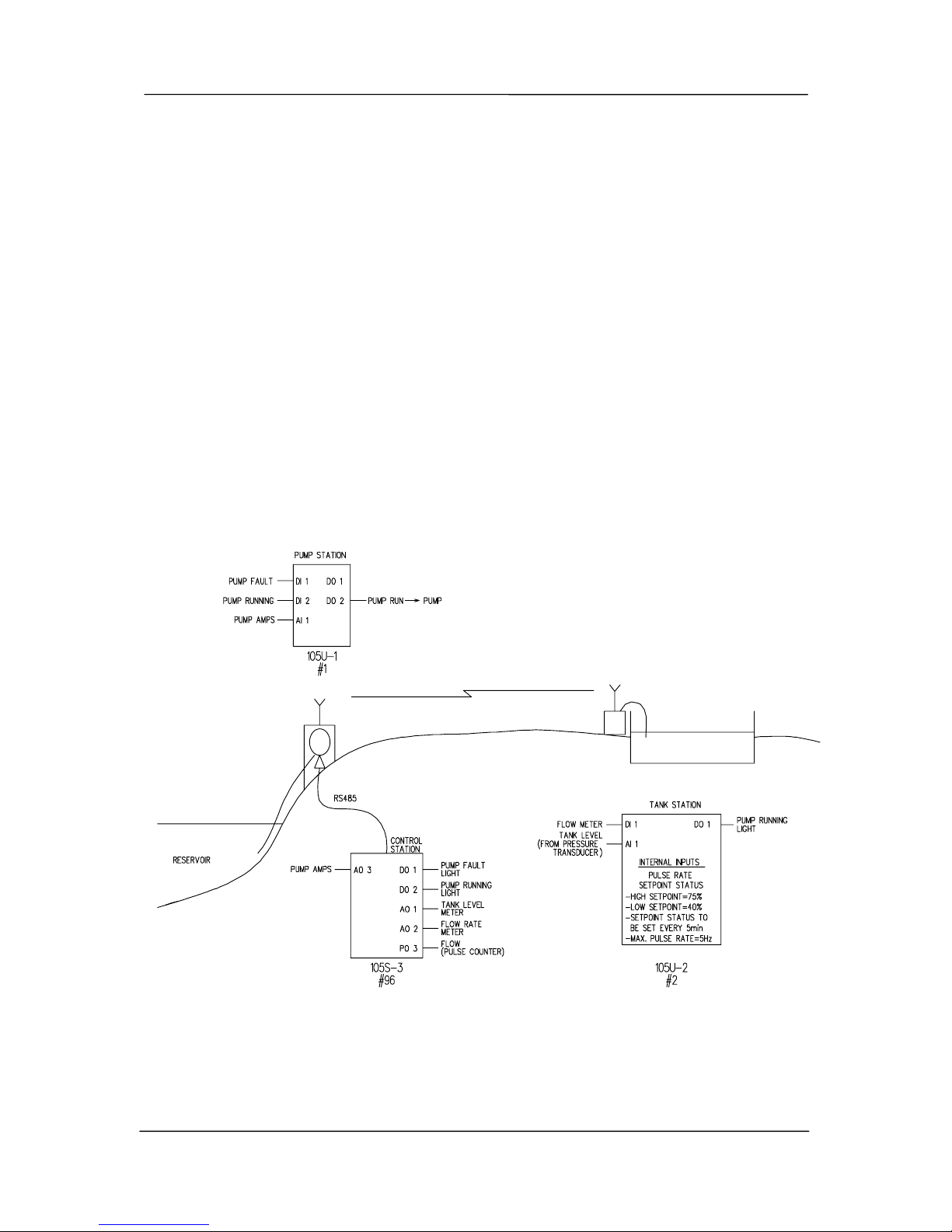
Appendix A System Example
man_105_2.9.doc Page 69
Appendix A SYSTEM EXAMPLE
The following example of a system is a comprehensive guide to using some of the features of
the 105 range and design of 105 system.
The example application is a pump station which supplies water from a reservoir to a tank
station. Signals are transferred between the pump station and tank station by radio - the
distance between the two stations is 1.5 km (1 mile), and the radio path is heavily obstructed
by buildings and trees. A control station is located near the pump station, and there is an
existing signal cable between the control station and the pump station.
A 105U-1 module is installed at the pump station (with address 1) and a 105U-2 module is
installed at the tank station (with address 2). Because the signal cable to the control station
does not have enough cores for all of the signals required, the signal cable is used as a RS485
cable and a 105S-3 module is installed at the control station (with address 96). As this
module has an address greater than 95, the 105U-1 at the pump station will communicate to it
via its serial port.
The following diagram represents the system :-
Page 70

105 Radio/Serial Telemetry Module User Manual
Page 70 © January 2004
The following design points should be noted :-
• A test of the radio path between the pump station and the tank station indicated that the
radio path would be reliable provided antennas were installed at 6 m above the ground.
At each site, the coaxial cable would be approx 10 m in length, so it was decided to use
3 element Yagi antennas with RG58 coaxial cable - the Yagi antennas would
compensate for the loss in the cable.
The system was installed in a country which permitted the use of 500mW radio power. If
this had not been the case, then an intermediate repeater station would have been required.
• At the tank station, there was an existing light pole with a mains power supply - the light
pole was 10m high. Permission was obtained to mount the antenna from the pole and to
use the power supply for the radio telemetry module.
As there was no existing electrical panel at this station, a small steel enclosure was
installed on the light pole. A 2 Amp-Hour sealed battery was installed to provide power
during any mains failure. The flow and level transducer were powered from the 24VDC
loop supply provided by the 105 module.
• At the pump station, the antenna was mounted on a 3 m J-bracket installed on the roof of
the pump station building. The final height of the antenna was approx 6 m. Care was
taken to align the Yagi antennas so they pointed at each other. The Yagi antennas were
installed with horizontal polarity - that is, with the elements horizontal. These antennas
will not "hear" other radio users on the same radio channel which generally use vertical
polarity.
There was an existing electrical enclosure at the pump station, and the 105U module was
installed inside this enclosure. The module was powered from 220VAC mains with a 2
Amp Hour sealed battery as backup.
• At the control station, the 105S module was installed inside the existing control panel
enclosure. The module was powered from an existing 24VDC power supply.
Page 71
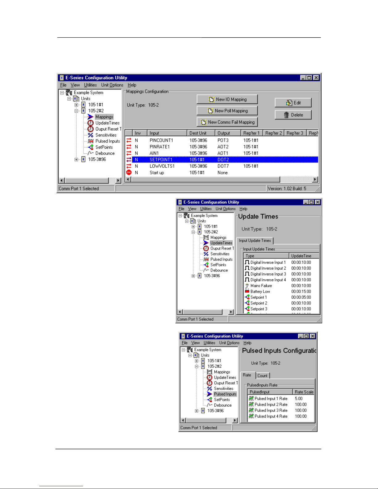
Appendix A System Example
man_105_2.9.doc Page 71
Tank Station Configuration
The 105U-2 module has the following configuration :-
Note the following points in the
configuration :
• #1 is a repeater for communications
between #2 and #96
• The pulse rate scaling for PIN1 has
been set to 5 Hz to match the
maximum flow rate of the flow
meter. Note that PIN1 has not been
configured for "divide by 10" (for
1000 Hz pulse signals).
• AIN1 (the level transducer) is
mapped to AO1 at the 105U-3. The
analogue debounce has been set to 2
sec. This is because of concern of
wave action on the surface of the tank
causing un-necessary change
transmissions. This debounce time
will also operate on the Pulse Rate
value, but as the flow rate changes
slowly, this will not affect the
performance of this signal.
• SETPOINT1 (the set-point status for
AI1) is mapped to DO2 of #1 (pump
station). The set-point values for this
setpoint have been set to 40% and
75%. When the tank level drops to
Page 72
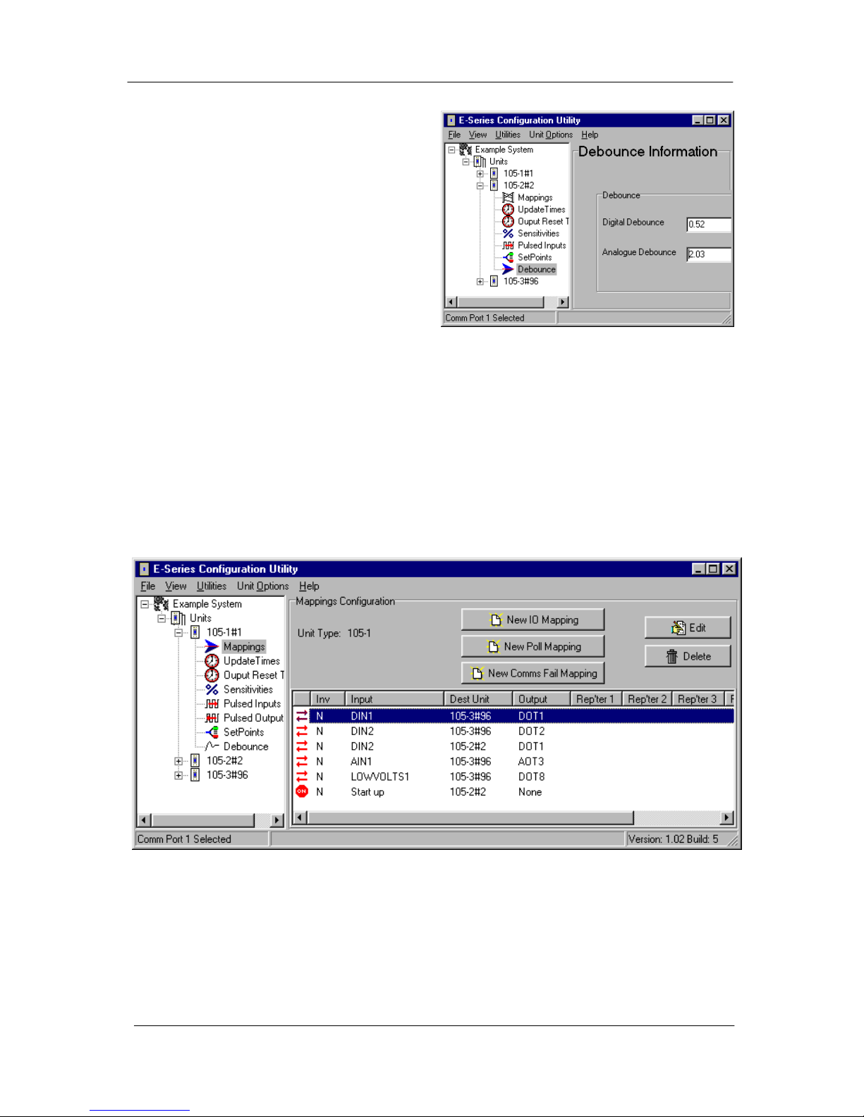
105 Radio/Serial Telemetry Module User Manual
Page 72 © January 2004
40%, DO2 at the pump station will
activate to start the pump. When the level
rises above 75%, DO2 will reset to stop
the pump.
• The update time for SETPOINT1 has been
changed to 5 minute, as required.
• An additional mapping has been entered -
LOW VOLT has been mapped to DO7 at
#96 via #1 (DO7 at the control station).
This mapping is for future use - it will
provide a low battery voltage alarm for the
tank station. The update time for this mapping has been set to the maximum time of 15
minutes to reduce loading of the radio channel.
• A Start-up poll has been configured for #1, as DO1 at the tank station is controlled from
the pump station. Note that no comms fail reset time has been configured for DO1. As
this output drives an indication only, the indication will show the last correct status even
during communication failures.
Pump Station Configuration
The 105U-1 module has the following configuration :-
Page 73
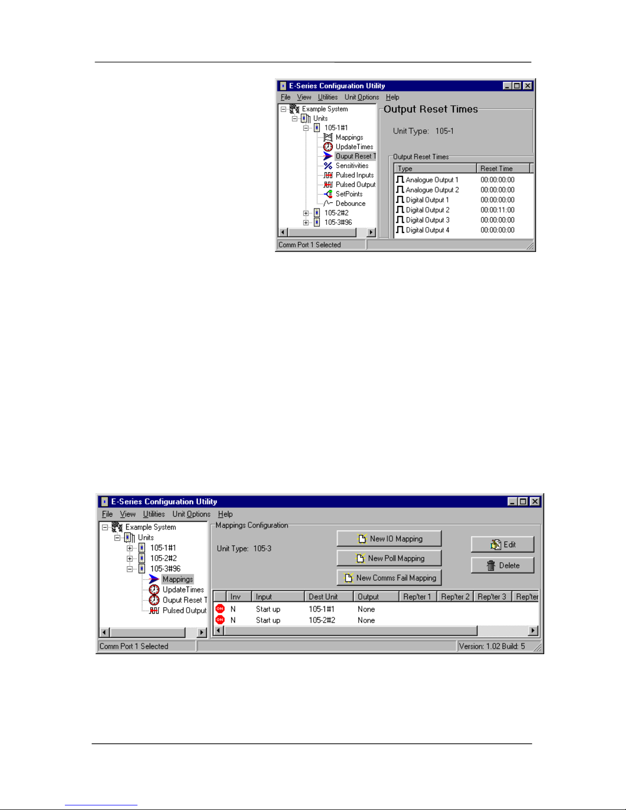
Appendix A System Example
man_105_2.9.doc Page 73
Note the following points in the
configuration:
• Note that no repeater address is
necessary between #1 and #96.
• DIN2 (pump running signal) has
two mappings - a mapping to
DO1 at #2 (tank station) and DO2
at #96 (control station). When
DIN2 changes, there will be two
separate change messages
transmitted - one by radio to #2
and one by serial link to #96.
• AIN1 (pump amps) is mapped to AO3 at #97 (control station).
• An additional mapping has been entered - LOW VOLT has been mapped to DO8 at the
control station. This mapping is for future use - it will provide a low battery voltage
alarm for the pump station.
• A Start-up poll has been configured for #2, as DO2 at the pump station is controlled from
the tank station. Note that a comms fail reset time of 11 minutes has been configured for
DO2. This means that if a message has not been received for DO2 within 11 minutes,
DO2 will reset and switch off the pump. The 11 min time was chosen as it means that two
successive update messages have to be missed before the pump is reset, and there is no
problems if the pump runs for 11 minutes during a system failure (the tank will not
overflow during this time).
Control Station Configuration
The 105S-3 module has the following configuration :-
Note the following points in the configuration :
• The only mappings are Start-up polls. Note that there are two separate polls, one for each
remote module.
• PO 3 has been configured as a PO. Its pulse output update time is the same as the PI
Page 74
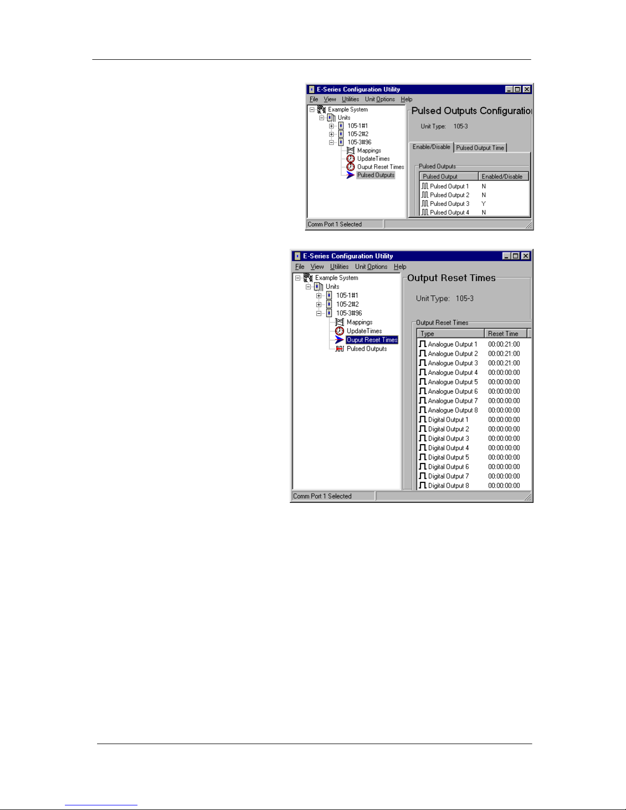
105 Radio/Serial Telemetry Module User Manual
Page 74 © January 2004
update time at the remote module (both
have been left at their default value of
1 minute).
• Reset times have been selected for the
analogue outputs (21 minutes) but not
the digital outputs. In the event of a
system failure, the digital outputs will
stay at their last correct status, but the
analogue outputs will reset to 0 mA.
System Failure Alarm
After the system had been running for
some time, the operators wanted a
"system failure" output at the control
station, to warn the operators that
there was a fault with the system.
The following configuration was
added:
At #2 (tank station), Inverse DI4 →
DO4 at #96 via 1 ; DI4 Update time =
1 minute
At #96 (control station), DO4 Comms
fail reset time = 3.5 min
At the control station, DO4 was a
"system OK" signal. It was normally
active - if the signal reset, then this
represented a system failure. At the
tank station, there is no signal wired
to DI4. By mapping Inv DI4 to DO4
at the control station, a message is transmitted every minute to this output to activate it. The
message is transmitted via the radio link to #1, and then by the serial link to #96. If anything
happened to either module #2 or module #1, or the radio link, or the serial link, then the
update messages for DO4 will not be received at the control station module. After 3.5
Minutes, DO4 will reset indicating a problem.
The time of 3.5 minutes was selected as this means that 3 successive update messages have to
be missed before a system alarm occurs. Also note, that if module #96 fails, DO4 will reset
and give an alarm signal.
Page 75
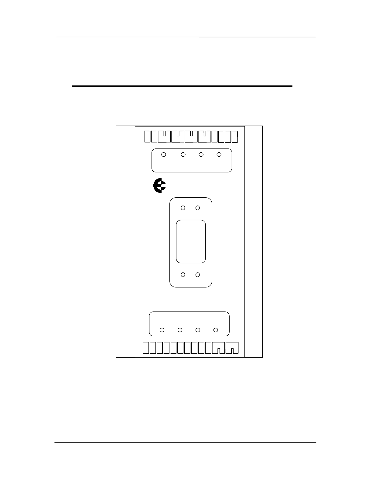
Appendix B Terminal Layouts
man_105_2.9.doc Page 75
Appendix B TERMINAL LAYOUTS
-
+AI 2
-
+AI 1
+24V
DI 3
SOL
DI 2
DI 1
GND
COM
DI 4
SUP2
SUP1
BAT+
DO 1
DO 2
DO 4
DO 3
GND
+24V
AO 1
AO 2
PO
1
2
3
4
OUTPUTS
1
3
4
INPUTS
ELPRO xxxx-1
WIRING DRAWING - 105U-1, 905U-1 105S-1
Page 76
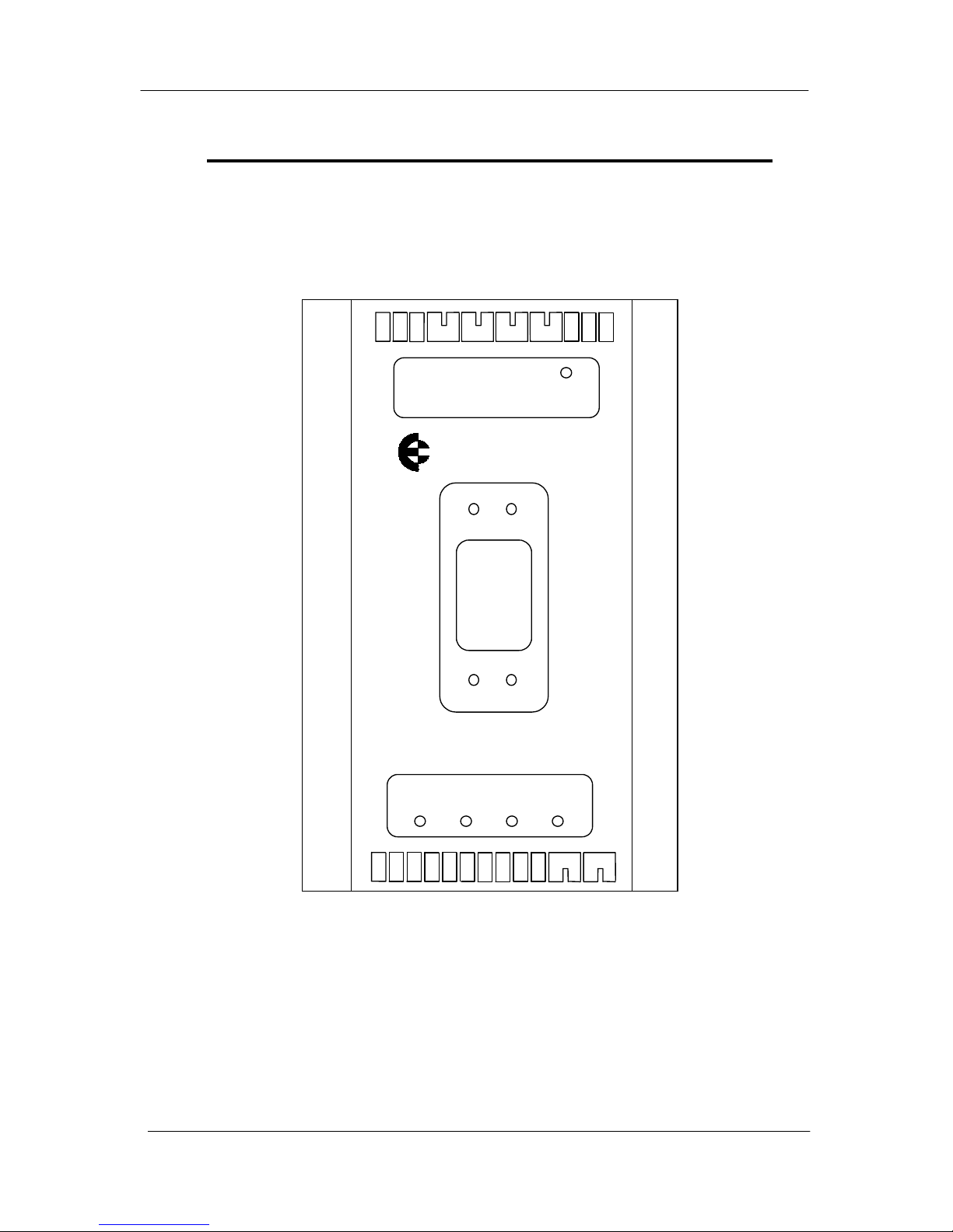
105 Radio/Serial Telemetry Module User Manual
Page 76 © January 2004
-
+AI 2
-
+AI 1
+24V
DI 3
SOL
DI 2
DI 1
GND
COM
DI 4
SUP2
SUP1
BAT+
AI 3+
AI 4+
AI 6+
AI 5+
GND
+24V
DOT
COM
COM
OUTPUT
1
3
4
INPUTS
ELPRO xxxx-2
WIRING DRAWING - 105U-2, 905U-2 105S-2
Page 77
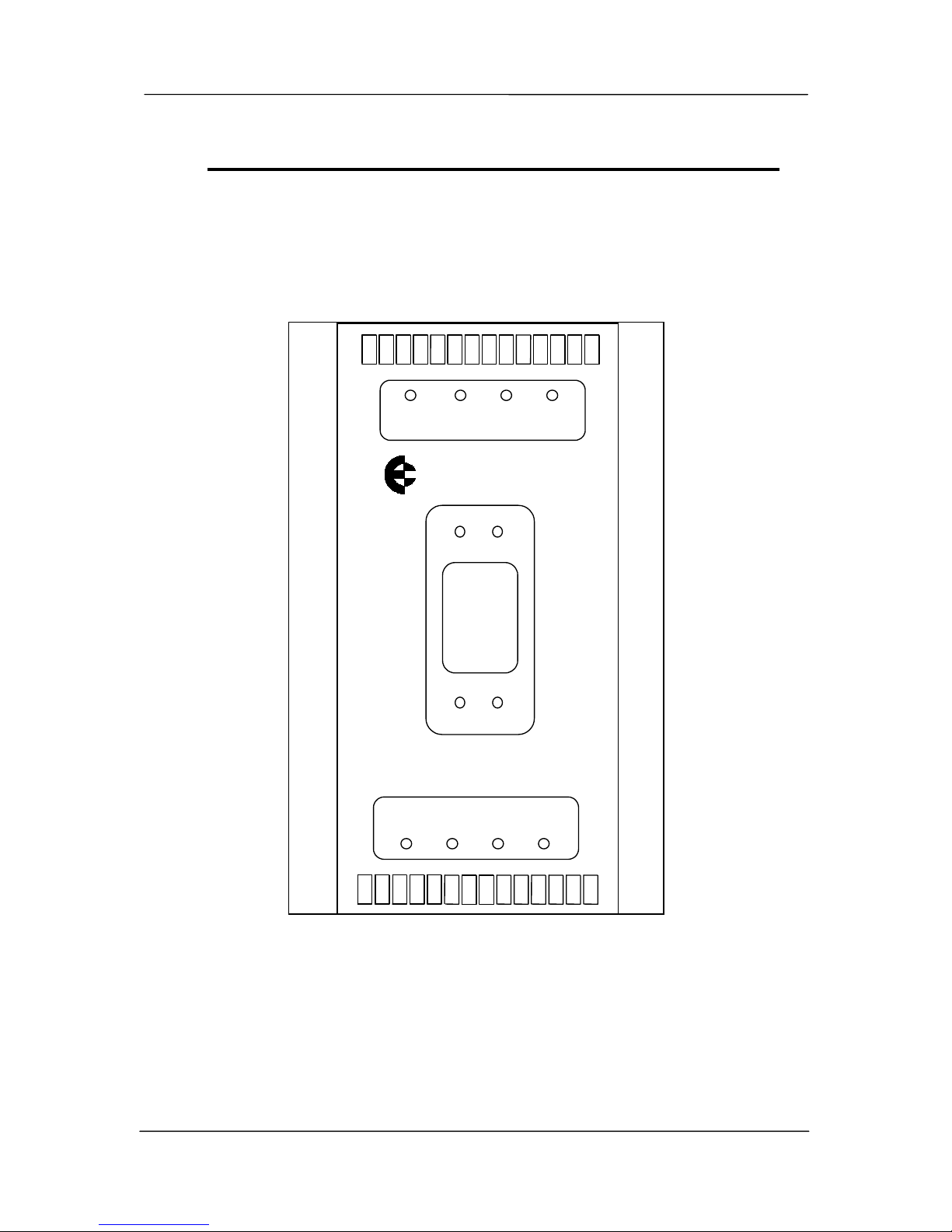
Appendix B Terminal Layouts
man_105_2.9.doc Page 77
DO 3
SOL
DO 2
DO 1
GND
COM
DO 4
SUP2
SUP1
BAT+
GND
AO 6
AO 7
AO 8
1
2
3
4
OUTPUTS
1
3
4
OUTPUTS
ELPRO xxxx-3
COM
COM
DO 5
DO 6
DO 7
DO 8
+24V
AO 5
+24V
AO 1
AO 2
AO 3
AO 4
+24V
WIRING DRAWING - 105U-3, 905U-3, 105S-3
Page 78
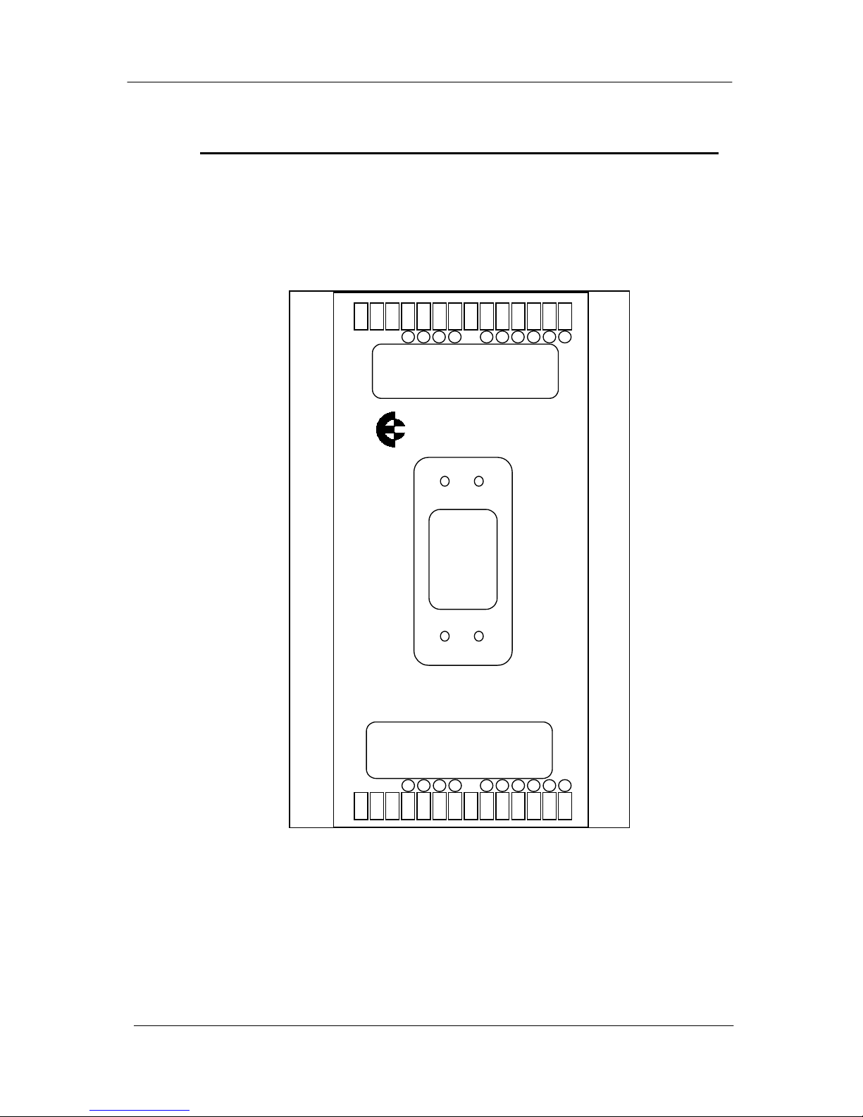
105 Radio/Serial Telemetry Module User Manual
Page 78 © January 2004
OUTPUTS
ELPRO xxxx-4
DIO9
DIO10
DIO11
DIO12
DIO8
DIO7
COM
DO 4
DO 3
DO 2
DO 1
SOL
GND
BAT+
I/0
INPUTS I/0
DIO3
DIO4
DIO5
DIO6
DIO2
DIO1
COM
DI 4
DI 3
DI 2
DI 1
GND
SUP2
SUP1
WIRING DRAWING - 105U-4, 905U-4, 105S-4
 Loading...