

ELPRO 905U, 905U-G, 905U-C, 905U-K, 905U-D User Manual
...
For 905U-C, 905U-G, 905U-K and 905U-D products,
refer to separate User Manuals
ELPRO Technologies Pty Ltd, 9/12 Billabong Street, Stafford Q 4053, Australia.
Tel: +61 7 33528600 Fax: +61 7 33528677 Email: sales@elprotech.com
Web: www.elprotech.com
User Manual
905U Wireless I/O Module
105S Serial I/O Module
also includes 105U 5W Wireless I/O range for licensed
frequencies in the 380 – 520 MHz band

905U Wireless I/O Module User Manual
105S Serial I/O Module
Page 2 © January 2011
Thank you for your selection of the 905U / 105S module for your I/O needs. We trust it will give you
many years of valuable service.
ATTENTION!
Incorrect termination of supply wires may
cause internal damage a nd will void warranty.
To ensure this product enjoys a long life,
double check ALL your connections with
the user’s manual
before turning the power on.
Caution!
For continued protection against risk of fire, replace th e module fuse F1 only with
the same type and rating.
CAUTION:
To comply with FCC RF Exposure requirements in section 1.1310 of the FCC Rules, antennas used
with this device must be installed to provide a separation distance of at least 33 cm from all persons
to satisfy RF exposure compliance.
DO NOT:
• operate the transmitter when someone is within 33 cm of the antenna
• operate the transmitter unless all RF connectors are secure and any open connectors are properly
terminated.
• operate the equipment near electrical blasting caps or in an explosive atmosphere
All equipment must be properly grounded for safe operations. All equipment should be serviced only
by a qualified technician.

Contents
man_905-105_2.16 Page 3
FCC Notice: 905U Wireless I/O Module
This user’s manual is for the ELPRO 905U wireless I/O module. This device complies with Part
15.247 of the FCC Rules.
Operation is subject to the following two conditions:
1) This device may not cause harmful interference and
2) This device must accept any interference received, including interference that may cause
undesired operation.
NOTE: This equipment is suitable for use in Class I Division 2 groups A, B C and D or non-hazardous
locations only
This device must be operated as supplied by ELPRO Technologies. Any changes or modifications
made to the device without the written consent of ELPRO Technologies may void the user’s authority
to operate the device.
End user products that have this device embedded must be installed by experienc ed radio and antenna
personnel, or supplied with non-standard antenna connectors, and antennas available from vendors
specified by ELPRO Technologies. Please contact ELPRO Technologies for end user antenna and
connector recommendations.
Notices: Safety
Exposure to RF energy is an important safety consideration. The FCC has adopted a safety standar d for
human exposure to radio frequency electromagnetic energy emitted by FCC regulated equipment as a
result of its actions in Docket 93-62 and OET Bulletin 65 Edition 97-01.
FCC Notice: 105U Wireless I/O Module
Part 15 – This device has been tested and found to comply with the limits for a Class B digital
device, pursuant to Part15 of the FCC rules (Code of Federal Regulations 47CFR Part 15).
Operation is subject to the condition that this device does not cause harmful interference.
Part 90 – This device has been type accepted for operation by the FCC in accordance with Part90 of
the FCC rules (47CFR Part 90). See the label on the uni t for the specific FCC ID and any
other certification designations.
Industry Canada: 105U Wireless I/O Module
RSS-119 - This device has been type accepted for operation by Industry Canada in acc ordance with
RSS-119 of the Industry Canada rules. See the label on the unit for the specific Industry
Canada certification number and any other certification designations.
Notice Any changes or modifications not expressly approved by ELPRO Technologies P/L could
void the user’s authority to operate this equipment.
To operate this equipment legally the user must obtain a radio operating license from the
government agency. This is done so the government can coordinate radio users in order to
minimize interference.

905U Wireless I/O Module User Manual
105S Serial I/O Module
Page 4 © January 2011
Important Notice
ELPRO products are designed to be used in industrial environments, by experienced industrial
engineering personnel with adequate knowledge of safety design considerations.
ELPRO radio products are used on unprotected license-free radio bands with radio noise and
interference. The products are designed to operate in the presence of noise and interference, however
in an extreme case, radio noise and interference could cause product operation delays or operation
failure. Like all industrial electronic products, ELPRO products can fail in a variet y of modes due to
misuse, age, or malfunction. We recommend that users and designers design systems using design
techniques intended to prevent personal injury or damage during product operation, and provide
failure tolerant systems to prevent personal inj ury or damage in the event of product failur e. Designers
must warn users of the equipment or systems if adequate protection against failure has not been
included in the system design. Designers must include this Important Notice in operating procedures
and system manuals.
These products should not be used in non-industrial applications, or life-support systems, without
consulting ELPRO Technologies first.
1. For 905U modules, a radio licence is not required in many countries, provided the module is
installed using the antenna and equipment configuration complying with the country’s
regulations.. Check with your local distributor for further information on regulations.
2. For 905U modules, operation is authorised by the radio frequency regulatory authori ty in your
country on a non-protection basis. Although all care is taken in the design of these units, there
is no responsibility taken for sources of external interference. The 905U intelligent
communications protocol aims to correct communication errors due to interference and to
retransmit the required output conditions regularly. However some delay in the operation of
outputs may occur during periods of interference. Systems should be designed to be tolerant of
these delays.
3. To avoid the risk of electrocution, the antenna, antenna cable, serial cables and all terminals of
the 905U/105S module should be electrically protected. To provide maximum surge and
lightning protection, the module should be connected to a suitable earth and the antenna,
antenna cable, serial cables and the module should be installed as recommended in the
Installation Guide.
4. To avoid accidents during maintenance or adjustment of remotely controlled equipment, all
equipment should be first disconnected from the 905U/105S module during these adjustments.
Equipment should carry clear markings to indicate remote or automatic operation. E.g. "This
equipment is remotely controlled and may start without warning. Isolate at the switchboard
before attempting adjustments."
5. The 905U/105S module is not suitable for use in explosive environments without additional
protection. These modules are approved for use in Class 1 Division 2 areas in North America.

Contents
man_905-105_2.16 Page 5
Limited Lifetime Warranty, Disclaimer and Limitation of Remedies
ELPRO products are warranted to be free from manufacturing defects for the “serviceable lifetime” of
the product. The “serviceable lifetime” is limited to the availability of electronic components. If the
serviceable life is reached in less than three years following the original purchase from ELPRO,
ELPRO will replace the product with an equivalent product if an equivalent product is available.
This warranty does not extend to:
- failures caused by the operation of the equipment outside the particular product's specification, or
- use of the module not in accordance with this User Manual, or
- abuse, misuse, neglect or damage by external causes, or
- repairs, alterations, or modifications undertaken other than by an authorized Service Agent.
ELPRO’s liability under this warranty is limited to the replacement or repair of the product. This
warranty is in lieu of and exclusive of all other warranties. This warranty does not indemnify the
purchaser of products for any consequential claim for damages or loss of operations or profits and
ELPRO is not liable for any consequential damages or loss of operations or profits resulti ng from the
use of these products. ELPRO is not liable for damages, losses, costs, injury or harm incurred as a
consequence of any representations, warranties or conditions made by ELPRO or its representatives or by
any other party, except as expressed solely in this document..
How to Use This Manual
To receive the maximum benefit from your 905U/105S product, please read the Introduction,
Installation and Operation chapters of this manual thoroughly before putting the product to work.
Chapter Four Configuration expl ains how to configure the modules using the Configuration Software
available.
Chapter Five Specifications details the features of the product and lists the standards to which the
product is approved.
Chapter Six Troubleshooting will help if your system has problems and Chapter Seven specifies the
Warranty and Service conditions.
The foldout sheet Installation Guide is an installation drawing appropriate for most applications.

905U Wireless I/O Module User Manual
105S Serial I/O Module
Page 6 © January 2011
CONTENTS
CHAPTER ONE INTRODUCTION .................................................................................................. 8
1.1 GENERAL ................................................................................................................................... 8
CHAPTER TWO INSTALLATION ................................................................................................ 11
2.1 GENERAL ................................................................................................................................. 11
2.2 ANTENNA INSTALLATION (905U & 105U UNITS ONLY) ............................................................ 11
2.2.1 Dipole and Collinear antennas. ........................................................................................... 13
2.2.2 Yagi antennas. ..................................................................................................................... 13
2.3 POWER SUPPLY ........................................................................................................................ 15
2.3.1 AC Supply ........................................................................................................................... 15
2.3.2 DC Supply ........................................................................................................................... 15
2.3.3 Solar Supply ........................................................................................................................ 16
2.3.4 Multiple Modules ................................................................................................................ 17
2.3.5 24V Regulated Supply ........................................................................................................ 18
2.4 INPUT / OUTPUT ....................................................................................................................... 18
2.4.1 Digital Inputs (905-1, 905-2 and 905-4) ............................................................................. 18
2.4.2 Digital Outputs (905-1) ....................................................................................................... 18
2.4.3 Digital Outputs (905-2, 905-3 and 905-4) .......................................................................... 19
2.4.4 Analog Inputs (905-1 and 905-2) ........................................................................................ 19
2.4.5 Analog Outputs (905-1 and 905-3) ..................................................................................... 21
2.4.6 Pulse Input (905-1) ............................................................................................................ 23
2.4.7 Pulse Inputs (905-2 and 905-4) .......................................................................................... 23
2.4.8 Pulse Output (905-1) ........................................................................................................... 24
2.4.9 Pulse Output (905-3 and 905-4) .......................................................................................... 24
COUNT+ ........................................................................................................................................ 24
2.4.10 RS232 Serial Port ............................................................................................................ 25
2.4.11 RS485 Serial Port ............................................................................................................ 25
2.4.12 Connecting 105S Modules to 905U Modules ................................................................. 26
CHAPTER THREE OPERATION .................................................................................................. 27
3.1 POWER-UP AND NORMAL OPERATION ...................................................................................... 27
3.1.1 Communications ................................................................................................................. 27
3.1.2 Change of state conditions .................................................................................................. 29
3.1.3 Analog Set-points ................................................................................................................ 32
3.1.4 Start-up Poll ........................................................................................................................ 32
3.1.5 Communications Failure (CF) ............................................................................................ 32
3.1.6 Resetting Outputs ................................................................................................................ 33
3.2 SYSTEM DESIGN TIPS ............................................................................................................... 33
3.2.1 System Dynamics ................................................................................................................ 33
3.2.2 Radio Channel Capacity ..................................................................................................... 33
3.2.3 Radio Path Reliability ......................................................................................................... 34
3.2.4 Design for Failures .............................................................................................................. 34

Contents
man_905-105_2.16 Page 7
3.2.5 Indicating a Communications Problem ............................................................................... 35
3.2.6 Testing and Commissioning................................................................................................ 36
3.3 SECURITY CONSIDERATIONS .................................................................................................... 36
CHAPTER FOUR CONFIGURATION .......................................................................................... 37
4.1 INTRODUCTION ........................................................................................................................ 37
4.2 EASY CONFIGURATION USING DEFAULT SETTINGS ................................................................. 38
4.3 CONFIGURATION SOFTWARE .................................................................................................... 40
4.3.1 Hardware and Software Requirements ............................................................................... 40
4.3.2 Program Operation .............................................................................................................. 40
4.3.4 Loading Configuration from a Module ............................................................................... 52
4.3.5 Modifying and Archiving Configuration Files ................................................................... 52
4.3.6 Print Options ....................................................................................................................... 53
4.3.7 Security ............................................................................................................................... 53
4.3.8 Using 105S Modules ........................................................................................................... 55
CHAPTER FIVE SPECIFICATIONS ............................................................................................. 58
5.1 DIMENSIONED DRAWING ......................................................................................................... 61
CHAPTER SIX TROUBLESHOOTING ....................................................................................... 63
6.1 DIAGNOSTICS CHART ............................................................................................................... 63
6.2 SELF TEST FUNCTIONS ............................................................................................................. 64
6.2.1 Input to Output Reflection (905U-1/105S-1 only) ............................................................. 64
6.2.2 Radio Testing using Tone Reversals (105U/905U modules only) ..................................... 64
6.2.3 Diagnostics menu ................................................................................................................ 64
6.2.4 Comms Logging .................................................................................................................. 71
6.3 RADIO PATH TESTING .............................................................................................................. 73
CHAPTER SEVEN WARRANTY & SERVICE ............................................................................ 75
APPENDIX A SYSTEM EXAMPLE ........................................................................................... 76
APPENDIX B TERMINAL LAYOUTS .......................................................................................... 82

905U Wireless I/O Module User Manual
105S Serial I/O Module
Page 8 © January 2011
Chapter One INTRODUCTION
1.1 General
The 905U, 105U & 105S range of I/O modules has been designed to provide standard “off-the-shelf”
telemetry functions, for an economical price. Telemetry is the transmission of signals over a long
distance via a medium such as radio or twisted-pair wire. Although the 905U/105S is intended to be
simple in its application, it also provides many sophisticated features. This manual should be read
carefully to ensure that the modules are configured and installed to give reliable performance.
The unit can monitor and control the following types of signals:
Digital on/off signals
Example outputs - motor run, siren on
Example inputs - motor fault, tank overflow, intruder alarm
Analog continuously variable signals (0-20mA)
Example outputs - tank level indication, required motor speed
Example inputs - measured tank level, actual motor speed
Pulse frequency signals
Examples - electricity metering, fluid flow
Internal Status signals
Examples - analog battery voltage, power status, solar panel status and low battery
status.
The unit will monitor the input signals and transmit the signal information by radio or RS485 twisted
pair to another module or modules. At the remote unit, the signals will be reproduced as digital,
analog or pulse output signals. The modules also provide analog set points, so that a digital output may
be configured to turn on and off depending on the value of an analog input. The pulse I/O tr ansmits an
accumulated value and the pulses are reliably recreated at the remote unit regardless of ‘missed’
transmissions. The actual pulse rate is also calculated and is available as a remote analog output.
This manual covers the 905U, 105U and 105S modules. We have provided a summary on all products
available in the range, below.
• 905U-1, 905U-2, 905U-3 and 905U-4 modules have radio and serial communications. The
modules differ only in their input/output (I/O) design, and are compatible, i.e. they can be used to
communicate signals to each other in the same network. The 905U has a frequency hopping spread
spectrum 900MHz radio which is license-free in many countries.
• 105U-1, 105U-2, 105U-3 and 105U-4 modules are similar to the 905U range, except they have a
fixed frequency radio in the 380 – 520MHz band (configurable 0.5 – 5W RF power), suitable for

Chapter One Introduction
man_905-105_2.16 Page 9
licensed radio channels in most countries.
• 105S-1, 105S-2, 105S-3 and 105S-4 modules have only serial communications. All other
specifications are as per the 905U-1, 2, 3 & 4 modules. The 105S modules are compatible with
905U modules. 105S modules may be used for serial I/O applications, or as I/O expansion for
905U modules.
• The 905U-C and 905U-G modules provides an interface between host devices such as PLC’s or
SCADA computers, and a wireless I/O system comprising 905U modules. The 905U-C and 905UG allows 905U modules to act as remote wireless I/O for the host devices. For more information,
refer to the 905U-C or 905U-G User Manual.
The 905U radio has been designed to meet the requirements of unlicensed operation for remote
monitoring and control of equipment. That is, a radio licence is not required for the 905U modules in
many countries. See Chapter Five Specifications for details. The 105U radio is suitable for fixed
frequency licensed channels in the 380-520MHz band - that is, a radio license is required to use the
105U products, but not the 905U products.
I/O Types
905U-1
105U-1
105S-1
905U-2
105U-2
105S-2
905U-3
105U-3
105S-3
905U-4
105U-4
105S-4
Radio
Serial
Digital
Inputs (DI)
4 4 4 to 16
Digital
Outputs (DO)
4 (relay) 1 (FET) 8 (FET) 4 to 16 (FET)
Analog
Inputs (AI)
2 (4-20mA) 6 (0-20mA)
Analog
Outputs (AO)
2 (4-20mA) 8 (0-20mA)
Pulse Inputs
(PI)
1 (100Hz) 4 (1x1KHz,
3x100Hz)
4 (1x1KHz,
3x100Hz)
Pulse
Outputs (PO)
1 (100Hz) 4 (100 Hz) 4 (100 Hz)
Comments
PI is DI 1. PO is
separate to DO.
PI’s are the same
as DI’s.
PO’s are the same
as DO’s .
PI/ PO’s are the
same as DI/ DO’s.
Note regarding -4 modules. The 905U/105S-4 has a total of 20 digital I/O. Four are fixed inputs
(also PI’s) and four are fixed outputs (also PO’s). The other 12 are selectable individually as DI or
DO. The I/O range can vary from 16DI + 4DO to 4DI + 16DO or any combination in between.

905U Wireless I/O Module User Manual
105S Serial I/O Module
Page 10 © January 2011
Input signals connected to a module are transmitted to another module and appear as output signals.
These input signals may also be configured to appear as “inverted” signals on the output. A
transmission occurs whenever a "change-of-state" occurs on an input signal. A "change-of-state" of a
digital or digital internal input is a change from "off" to "on" or vice-versa. A "change-of-state" for an
analog input, internal analog input or pulse input rate is a change in value of the signal of 3%
(configurable from 0.8 to 75 %).
In addition to change-of-state messages, update messages are automatically transmitted on a regular
basis. The time period may be configured by the user for each input. This update ensures the integrity
of the system.
Pulse inputs are accumulated as a pulse count and the accumulated pulse count is transmitted regularly
according to the configured update time.
The I/O modules transmit the input/output data as a data frame using radio or serial RS485 as the
communications medium. The data frame includes the "address" of the transmitting module and the
receiving module, so that each transmitted message is acted on only by t he correct receivi ng unit. Each
transmitted message also includes error checking to ensure that no corruption of the data frame has
occurred due to noise or interference. The module with the correct receiving "address" will
acknowledge the message with a return transmission. If the original module does not receive a correct
acknowledgement to a transmission, it will retry up to five times before setting the communications fail
status of that path. In critical paths , this status can be reflected on an output on the module for alert
purposes. The module will continue to try to establish communications and retry, if required, each time
an update or change-of-state occurs.
A system may be a complex network or a simple pair of modules. An easy-to-use configuration
procedure allows the user to specify any output destination for each input.
The maximum number of modules in one system is 95 modules communicating by radio. Each of
these modules may have up to 31 other modules connected by RS485 twisted pair. Modules may
communicate by radio only, by RS485 only or by both RS485 and radio. Any input signal at any
module may be configured to appear at any output on any module in the entire system.
Systems with a 905U-C or 905U-G module and host device can have more than 95 radio modules.
Modules can be used as repeaters to re-transmit messages on to the destination module. Repeaters can
repeat messages on the radio channel, or from the radio channel to the serial channel (and serial to
radio). Up to five repeater addresses may be configured for each input-to-output link.
The units may be configured by using a PC connected to the RS232 port. The default configuration
and software configuration is defined in Section 4 Configuration.
Note: In this manual, reference to the 905U Wireless I/O units also relates to the 105U
Wireless I/O units.

Chapter Two Installation
man_905-105_2.16 Page 11
Chapter Two INSTALLATION
2.1 General
The 905U/105S module is housed in a rugged aluminium case, suitable for DIN-rail mounting.
Terminals are suitable for cables up to 2.5 sqmm in size.
All connections to the module should be SELV only. Normal 110/220/240V mains supply should
not be connected to any input terminal of the module. Refer to Section 2.3 Power Supply.
Each module should be effectively earthed/grounded via a "GND" terminal on the module - this
is to ensure that the surge protection circuits inside the module are effective. The earth/ground wire
should be connected to the same earth/ground point as the enclosure “earth” and the antenna mast
“earth”.
Before installing a new system, it is preferable to bench test the complete system. Configuration
problems are easier to re cognise when the system units are adjacent. Following installation, the most
common problem is poor communications on the radio channel or the serial channel. For radio
modules, problems are caused by incorrectly installed antennas, or radio interference on the same
channel, or the radio path being inadequate. If the radio path is a problem (i.e. path too long, or
obstructions in the way), then higher performance antennas or a higher mounting point for the antenna
may fix the problem. Alternately, use an intermediate module as a repeater.
For serial modules, poorly installed serial cable, or interference on the serial cable is a common
problem.
The foldout sheet Installation Guide provides an installation drawing appropriate to most applications.
Refer to Appendix B of this manual for terminal layout drawings of the modules.
2.2 Antenna Installation (905U & 105U units only)
The 905U module will operate reliably over large distances. The distance which may be reliably
achieved will vary with each application - depending on the type and location of antennas, the degree
of radio interference, and obstructions (such as hills or trees) to the radio path. Typical reliable
distances are :
USA/Canada 15 miles 6dB net gain antenna configuration permitted (4W ERP)
Australia/NZ 12 km unity gain antenna configuration (1W ERP)
Longer distances can be achieved if one antenna is mounted on top of a hill.
To achieve the maximum transmission distance, the antennas should be raised above intermediate
obstructions so the radio path is true “line of sight”. Because of the curvature of the earth, the
antennas will need to be elevated at least 15 feet (5 metres) above ground for paths greater than 3 miles
(5 km). The modules will operate reliably with some obstruction of the radio path, although the
reliable distance will be reduced. Obstructions which are close to either antenna will have more of a
blocking affect than obstructions in the middle of the r adio path. For exa mple, a group of trees around

905U Wireless I/O Module User Manual
105S Serial I/O Module
Page 12 © January 2011
the antenna is a larger obstruction than a group of trees further away from the antenna. The 905U
modules provide a test feature which displays the radio signal strength.
Line-of-sight paths are only necessary to obtain the maximum range. Obstructions will reduce the
range however, but may not prevent a reliable path. A larger amount of obstruction can be tolerated for
shorter distances. For very short distances, it is possible to mount the antennas i nside buildings. An
obstructed path requires testing to determine if the path will be reliable - refer the section 6 of this
manual.
Longer distances can be achieved using the licensed 105U units, because they use a lower frequency
and licensed conditions generally allow a higher RF power to be used.
Where it is not possible to achieve reliable communications between two modules, then a third module
may be used to receive the message and re-transmit it. This module is referred to as a repeater. This
module may also have input/output (I/O) signals connected to it and form part of the I/O network refer to Chapter 4 Configuration of this manual.
An antenna should be connected to the module via 50 ohm coaxial cable (eg RG58, RG213 or Cellfoil)
terminated with a male SMA coaxial connector. The higher the antenna is mounted, the greater the
transmission range will be, however as the length of coaxial cable increases so do cable losses. For
use on unlicensed frequency channels, there are several types of antennas suitable for use. It is
important antenna are chosen carefully to avoid contravening the maximum power limit on the
unlicensed channel - if in doubt refer to an authorised service provider.
The net gain of an antenna/cable configuration is the gain of the antenna (in dBi) less the loss in the
coaxial cable (in dB).
The maximum net gain of the antenna/cable configuration permitted for 905U is
Country Max. gain (dB)
USA / Canada 6
Australia / New Zealand 0
The gains and losses of typical antennas for 905U are
Standard Antennas Gain (dB) Elpro Part Nos.
Dipole with integral 15’ cable 0 CFD890EL
5dBi Collinear (3dBd) 5 SG900EL
8dBi Collinear (6dBd) 8 SG900-6
6 element Yagi 10 YU6/900
9 element Yagi 12 YU9/900
16 element Yagi 15 YU16/900
Cable type Loss (dB per 30 ft / 10 m)
RG58 -5
RG213 -2.5
Cellfoil -3
Chapter Two Installation
man_905-105_2.16 Page 13
The net gain of the antenna/cable configuration i s determined by adding the antenna gain and t he cable
loss. For example, a 6 element Yagi with 70 feet (20 metres) of Cellfoil has a net gain of 4dB (10dB –
6dB).
For information on antennas and cables for the 105U licensed products, please refer to ELPRO or an
authorized distributor.
Connections between the antenna and coaxial cable should be carefully taped to prevent ingress of
moisture. Moisture ingress in the coaxial cable is a common cause for problems with radio systems, as
it greatly increases the radio losses. We recommend that the connection be taped, firstly with a layer of
PVC Tape, then with a vulcanising tape such as “3M 23 tape”, and finally with another layer of PVC
UV Stabilised insulating tape. The first layer of tape allows the joint to be easily inspected when
trouble shooting as the vulcanising seal can be easily removed.
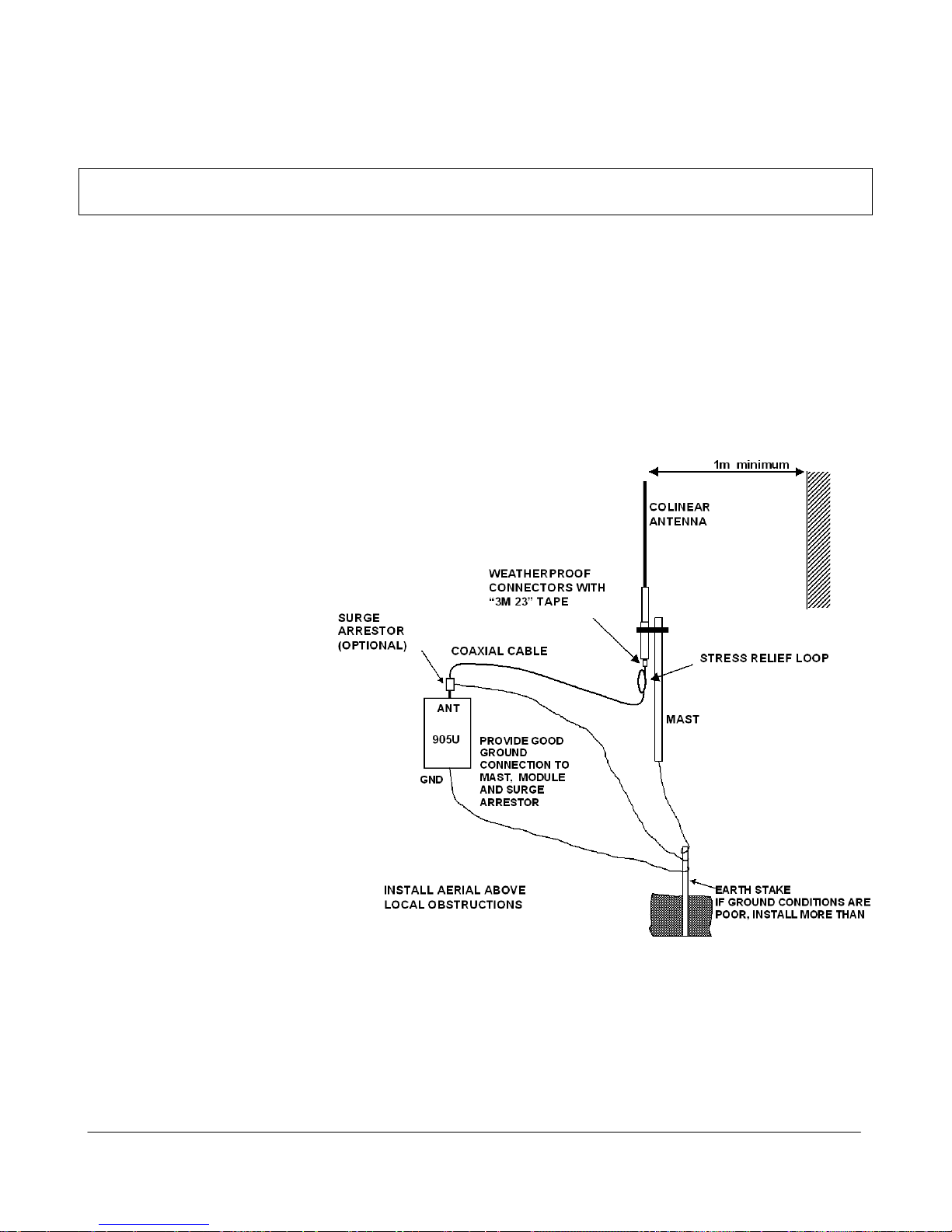
Where antennas are mounted on elevated masts, the masts should be effectively earthed to avoid
lightning surges. For high lightning risk areas, surge suppression devices between the module and the
antenna are recommended. If the antenna is not already shielded from lightning strike by an adjacent
earthed structure, a
lightning rod may be
installed above the antenna
to provide shielding.
2.2.1 Dipole and
Collinear antennas.
A collinear antenna
transmits the same amount
of radio power in all
directions - as such that
are easy to install and use.
The dipole antenna with
integral 15 feet cable does
not require any additional
coaxial cable, however a
cable must be used with the
collinear antennas.
Collinear and dipole
antennas should be
mounted vertically,
preferably 1 metre away
from a wall or mast to
obtain maximum range.
2.2.2 Yagi antennas.
A Yagi antenna provides high gain in the forward direc tion, but lower gain in other directions. This
may be used to compensate for coaxial cable loss for installations with marginal radio path.

905U Wireless I/O Module User Manual
105S Serial I/O Module
Page 14 © January 2011
The Yagi gain also acts on the receiver, so adding Yagi antennas at both ends of a link provides a
double improvement.
Yagi antennas are directional. That is, they have positive gain to the front of the antenna , but negative
gain in other directions. Hence Yagi antennas should be ins talled with the centra l beam horizontal and
must be pointed exactly in the direction of trans mission to benefit from the gain of the antenna. The
Yagi antennas may be installed with the elements in a vertical plane (vertically polarised) or in a
horizontal plane (horizontally polarised). For a two station instal lation, with both modules using Yagi
antennas, horizontal polarisation is recommended. If there are more than two stations transmitting to a
common station, then the Yagi antennas should have vertical polarisation, and the common (or
“central” station should have a collinear (non-directional) antenna.
Note that Yagi antennas normally
have a drain hole on the folded
element - the drain hole should be
located on the bottom of the
installed antenna.
905U
Antenna installed
with drain hole s
down
Coax feed looped
at connection
90
o
Protected area -
approx 45 deg angle
to vertical
Chapter Two Installation
man_905-105_2.16 Page 15
2.3 Power Supply
The 905U/105S power supply is a switch-mode design which will accept either AC or DC supply. The
module may also be powered from a solar panel without an external solar regulator.
The module accepts supply voltages in the following ranges :
12 - 24 volts AC RMS or 15 - 30 volts DC at the “supply” terminals, or
11.5 -15 volts DC at the “battery” terminals.
The power supply should be rated at 1.5 Amps and be CSA Certified Class 2. For use in Class 1 Div 2
explosive areas, the power supply must be approved for Class 1 Div 2 use.
Note: Connect module to the same ground/earth point as the antenna mounting to avoid differences in
earth potential during voltage surges. The modules needs an earth connection for the internal surge
protection to be effective.
For licensed 105U units with RF power above 2W, the unit needs to be powered from the 12V
“Battery” terminals with a power supply of at least 2A rating. Alternately, the unit can be
powered via the SUP1 / SUP2 terminals, provided a backup battery is connected to the
“Battery” terminals to supply the inrush current for the radio transmitter. This is not required
for units with radio power less than 2W.
2.3.1 AC Supply
The AC supply is connected to the "SUP1" and "SUP2" terminals as shown below.
The AC supply should be "floating" relative to earth. AC transformers with grounded/earthed
secondary windings should not be used.
2.3.2 DC Supply
For DC supplies, the positive lead is connected to "SUP1" and the negative to "GND". The positive
side of the supply must not be connected to earth. The DC supply may be a floating supply or
SUP1
SUP2
GND
SOL
12 – 24 VAC
Power
Supply
AC Out
BAT+
GND
- +
905U
Optional Battery
Fuse 2A
Optional Battery
Fuse 2A
_
+
SUP1
SUP2
GND
SOL
Power
Supply
DC Out
BAT+
GND
- +
905U
15 – 30 VDC
>17V if battery
is used
905U Wireless I/O Module User Manual
105S Serial I/O Module
Page 16 © January 2011
negatively grounded.
The module may also be powered from an external 11.5 - 15 VDC battery supply without the need for a
"normal" supply connected to "SUP1". This external battery supply is connected to "BAT+" and
"GND" terminals. The positive lead of the external supply should be protected by a 2A fuse.
Upon failure of the normal supply, the module may continue to operate for several hours from a backup
battery. The module includes battery charging circuits for charging up to a 12 AHr sealed lead acid
battery. The battery is connected to the "BAT+" (positive) and "GND" (negative) terminals. The
positive lead from the battery should be protected with a 2A fuse, installed as near to the battery
terminal as possible. On return of main supply, the unit will switch back to mains operation, and
recharge the battery. To provide adequate current to r echar ge the ba ckup batt ery, a n AC supply of 15V
minimum or a DC supply of 17V minimum must be used. Typically, a 6 AHr battery will supply the
905U for 1 - 3 days, depending on I/O loads.
2.3.3 Solar Supply
The power supply also includes a 12 V solar regulator for connecting 12V solar panels of up to 30W,
and solar batteries of up to 100AHr. The unit must not be powered from a solar panel without a
battery. A 20W solar panel is sufficient for most solar applications. The size of the solar battery
required depends on the I/O used. Batteries are sized for a number of sunless days with 50% battery
capacity remaining as follows:
No. of sunless days = Battery capacity (AHr) x 0.5
Module load (A) x 1.2 x 24
The Module load depends on the I/O connected and can be calculated as follows:
Module Load(mA) = (85 for 105U/905U or 45 for 105S) + (10 x No. of active DI’s) +
(25 x No. of active DO’s) + (2 x Analog loop load).
The analog loop load is the total signal current for the AI’s and AO’s which are powered from the
internal 24V supply. Externally powered loops are not included in this.
_
+
SUP1
SUP2
GND
SOL
BAT+
GND
-
+
905U
Solar Battery
Fuse 2A
Solar Panel
_
+
SUP1
SUP2
GND
SOL
Power
Supply
DC Out
BAT+
GND
905U
11.5 – 15 VDC
Fuse 2A
Chapter Two Installation
man_905-105_2.16 Page 17
The solar panel is connected to the "SOL" (positive) and "GND" (negative) terminals and the battery
connected to the "BAT+" (positive) and "GND" (negative) terminals. Solar panels must be installed
and connected as per the panel manufacturer's instructions. The positive lead of the battery should be
protected by a 2A fuse installed as near as possible to the battery terminal.
Where a panel larger than 30W is required, an external solar regulator should be used.
For maintenance, disconnect the solar panel first before disconnecting the battery.
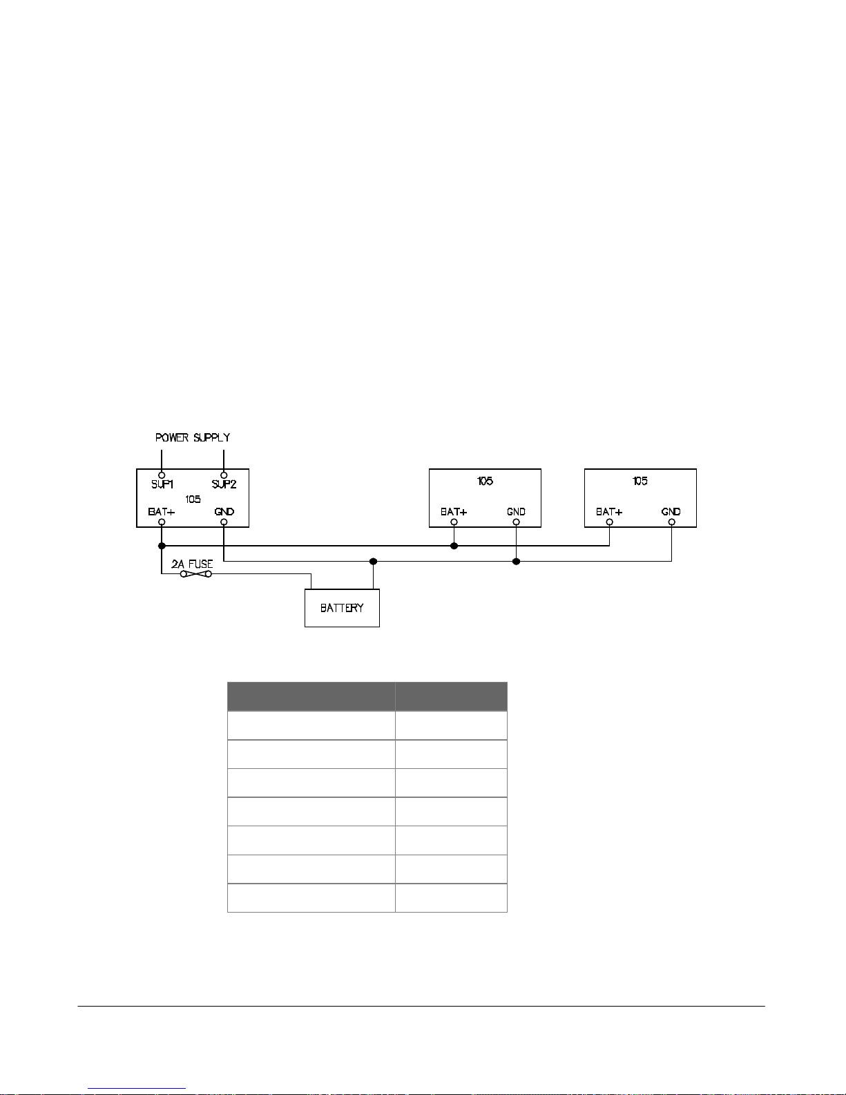
2.3.4 Multiple Modules
Where more than one module is installed at the one location, a shared power supply and battery may
be used, provided the total load does not exceed the power supply.
The internal power supply of the module can supply a maximum 12V load of 700mA. In order to
achieve this, the input power supply must be above 15VAC or 17VDC. Using these figures, it can be
determined whether there is enough supply for more than one module - allow 100mA for
recharging a battery.
For example, assume there is a 905U-1 module and a 105S-1 module at the same location. The total
I/O at the location is 3 analog inputs, 6 digital inputs and 4 digital outputs. The total load will be :-
TYPE OF LOAD LOAD mA
905U-01 quiescent 85
105S-01 quiescent 45
6 DI @ 10 mA 60
3 AI @ 20mA x 2 120
4 DO @ 25mA 100
Battery charging 100
TOTAL 510
So both modules could be powered from one power supply and one battery, provided the external
supply voltage is more than 15VAC or 17VDC.
905U Wireless I/O Module User Manual
105S Serial I/O Module
Page 18 © January 2011
2.3.5 24V Regulated Supply
Each module provides a 24V DC regulated supply for analog loop power, except for 905U-4/105S-4.
The supply is rated at 150mA, and should only be used for powering analog loops.
2.4 Input / Output
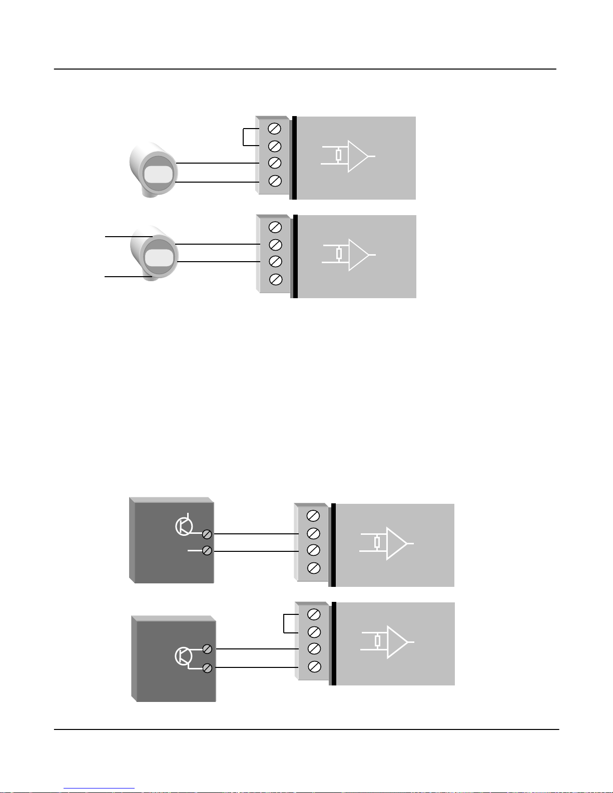
2.4.1 Digital Inputs (905-1, 905-2 and 905-4)
The ”-1” and ”-2” modules each provide four digital inputs with 5000 volt opto-isolation, and the ”-4”
provides 4 to 16 inputs with 3000 volt surge protection. All inputs are suitable for voltage free contacts
(such as mechanical switches) or NPN transistor devices (such as electronic proximity switches). PNP
transistor devices are not suitable. Contact wetting current of approximately 5mA is provided to
maintain reliable operation of driving relays.
Each digital input is connected between the appropriate "DI" terminal and common "COM". Each
digital input circuit includes a LED indicator which is lit when the digital input is active, that is, when
the input circuit is closed. Pr ovided the resistance of the switching device is less than 200 ohms, the
device will be able to activate the digital input.
For pulse inputs, refer to Section 2.4.6.
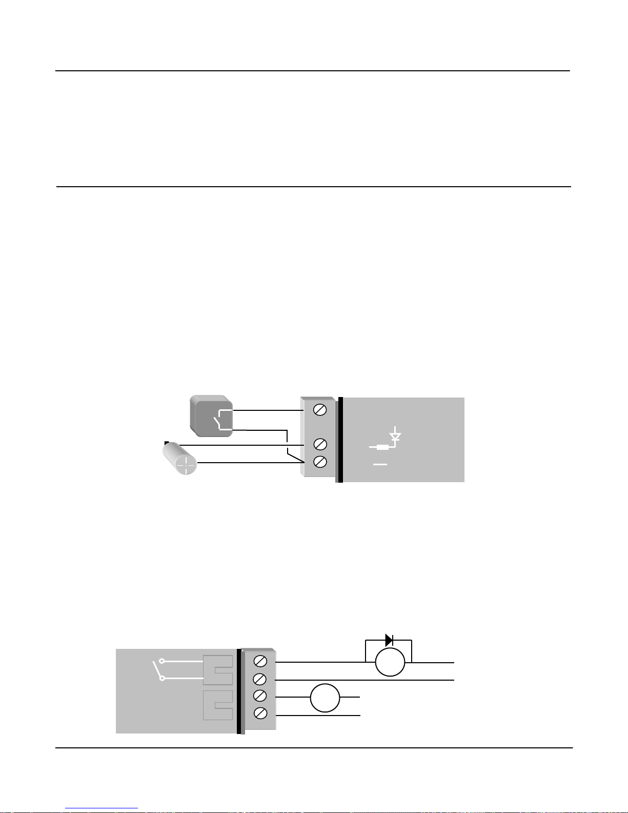
2.4.2 Digital Outputs (905-1)
The ”-1” module provides four normally open voltage-free relay contacts, rated at AC 50V/5A, DC
30V/2A, 20V/5A. These outputs may be used to directly control low-powered equipment, or to power
larger relays for higher powered equipment. When driving inductive loads such as AC relays, good
installation should include capacitors (e.g. 10nf 250V) across the external circuit to prevent arcing
across the relay contacts. For DC inductive loads, flyback diodes should be used across DC relays.
+
_
DI 1
DI 4
COM
905U
Voltage-free
contact input
Transistor
input
V+
V-
_
+
DO 1
DO 2
905U
Max 50VAC
5A
AC
Load
DC
Load
Max 30VDC
2A
Chapter Two Installation
man_905-105_2.16 Page 19
Digital outputs may be configured to individually turn off if no command message is received to that
output for a certain period. This feature provides an intelligent watch dog for each output, so that a
communications failure at a transmitting site causes the output to revert to a known state. See section
4.4 Changing User Options for further details.
The output circuit is connected to the appropriate pair of "DO" terminals. Each digital output circuit
includes a LED indicator which is lit when the digital output is active.
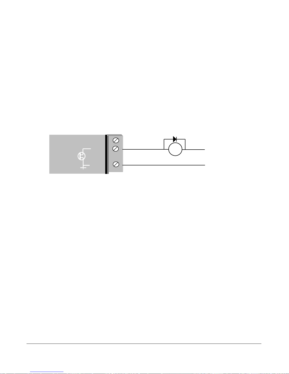
2.4.3 Digital Outputs (905-2, 905-3 and 905-4)
The digital outputs on the “-2”, “-3” and “-4” modules are transistor swit ched DC signals, FET output
to common rated at 30VDC 500 mA. The ”-2” provides one digital output; the ”-3” provides eight
digital outputs and the ”-4” provides 4 – 16 output s. The first four DO’s on the ”-3” and ”-4” modules
are also the pulse outputs - that is, the first four DO's can be either di gital outputs or pulse outputs.
The function of each of these outputs may be configured individually. For a description of pulse
outputs, refer to Section 2.4.7.
Digital outputs may be configured to individually turn off if no command message is received to that
output for a certain period. This feature provides an intelligent watch dog for each output, so that a
communications failure at a transmitting site causes the output to revert to a known state. See Chapter
4 Configuration for further details.
The output circuit is connected to the appropriate pai r of "DO" terminals. Each digital output circuit
includes a LED indicator which is lit when the digital output is active.
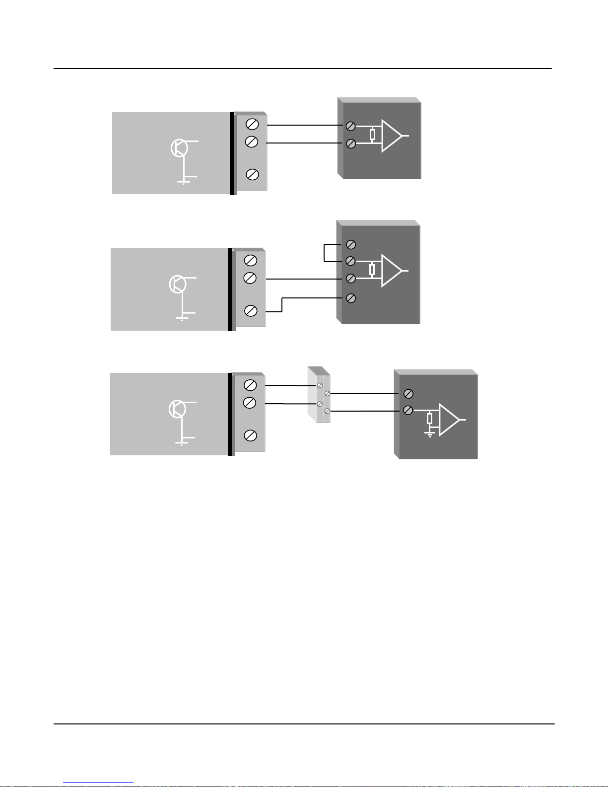
2.4.4 Analog Inputs (905-1 and 905-2)
The ”-1” module provides two 4 - 20 mA DC analog inputs for connecting to instrument transduc ers
such as level, moisture, pressure transducers, etc. The ”-2” module provides six 0 - 20 mA DC analog
inputs. Note that the inputs on the ”-2” module will measure down to 0mA, so they can also be used
for zero based signals such as 0 - 10 mA. The modules transmit the “mA value” of the input, not a “%
of range”, so the output value is set to the correct mA signal.
Each analog input has a positive and negative terminal, and may be placed at any point in the current
loop, as long as neither input rises above the 24 volt supply level. Each input has a loop resi stance of
less than 250 ohms and zener diode protection is provided against over-voltage and reverse voltage ,
however additional protection may be required in high voltage or noisy environments or for very long
wiring runs.
A 24VDC loop supply is available on the module for powering the analog transducer loops. I n this
case, the analog loop should be connected between a "AI 1-" terminal and "COM" ( for the first analog
input) or "AI 2-" ( for the second analog input), and so on for other inputs.
_
+
DO 1
DO 2
COM
905U
DC
Load
Max 30VDC
0.5A
905U Wireless I/O Module User Manual
105S Serial I/O Module
Page 20 © January 2011
The positive terminal ("AI 1+" or "AI 2+", etc) should be connected to "+24V".
Externally powered loops may be connected by connecting the input between "AI 1+" and “AI 1-” for
analog input 1 or "AI 2+" and “AI 2-” for analog input 2, and so on for other inputs. Common mode
voltage may be -0.5V to 27V.
Shielded cable is recommended for analog I/O loops to minimise induced noise and Radio Frequency
Interference (RFI). The shield of the cable should be connected to earth at one of the cable only. The
use of shielded wiring inside an enclosure containing a module is also recommended.
To connect an AI on the 905U to an analog signal from a PLC or DCS output, check the internal
circuit of the output carefully as different devices use different ways to create an analog signal. The
following diagram shows two ways of connecting.
AO
PLC
_
+24V
+AI
- AI
COM
905U
+24V
+AI
- AI
COM
905U
Current
source
output
Note:
1. AI must be
within 27V of COM.
If terminal voltages
exceed this, a loop
isolator must be
used.
2. COM on the
105U is connected
to ground/earth. If
the COM of the
PLC cannot be
grounded, then a
loop isolator must
be used.
+
+V
-V
AO
COM
PLC
Current
sink
output
4-20mA
+
_
+24V
+AI
- AI
COM
905U
2-wire
Input
+
_
+24V
+AI
- AI
COM
905U
4-wire
Input
External
Power
Note:
AI must be within
27V of COM. If
terminal voltages
exceed this, a
loop isolator must
be used.
Chapter Two Installation
man_905-105_2.16 Page 21
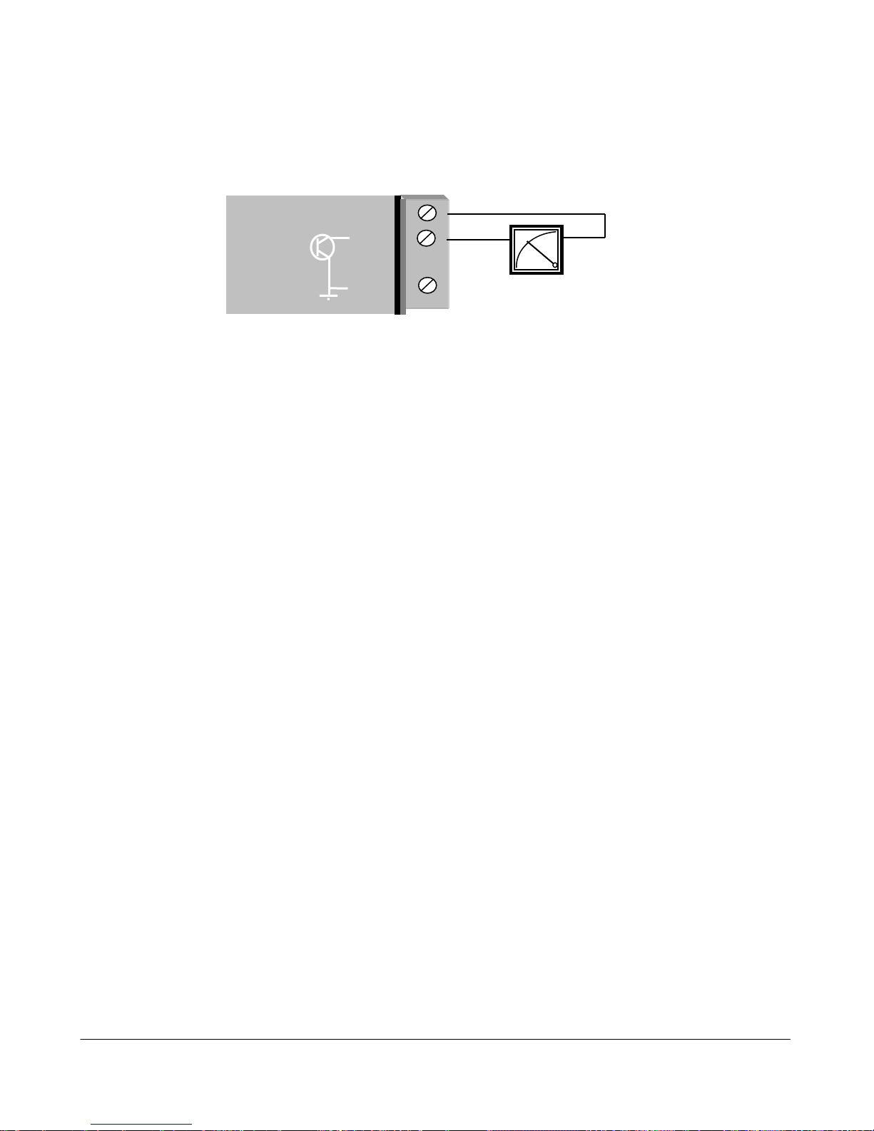
2.4.5 Analog Outputs (905-1 and 905-3)
The ”-1” module provides two 4 - 20 mA DC analog outputs for connecting to instrument indicators for
the display of remote analog measurements. The ”-3” module provides eight 0 - 20 mA DC analog
outputs. Each analog output is a "sink" to common.
A 24VDC supply is available on the module for powering the analog output loop (max external loop
resistance 1000 ohms). In this case, the analog loop is connected between a "+24V" terminal and "AO
1" ( for the first analog output) or "AO 2" (for the second analog output), and so on for the other
output signals.
If connecting to an external device such as an electronic indicator, recorder or PLC / DCS input, the
loop can be powered be either the 905U or the device. Externally powered loops to 27 VDC may be
connected by connecting the output between the "AO” terminal (positive) and the "COM" terminal
(negative). Zener protection of analog outputs provides protecti on against short per iods of over-voltage
but longer periods may result in module damage.
Note that the common is connected internally to ground and no other poi nt in the analog loop should
be grounded. If the external device has single-ended grounded inputs, t hen a signal isolator must be
used.
Analog outputs may also be configured to individually turn off (0 mA) if no command message is
received to that output for a certain period. . See Chapter 4 Configuration for further details.
_
+
+24V
AO 1
COM
905U
905U Wireless I/O Module User Manual
105S Serial I/O Module
Page 22 © January 2011
DEVICE
_
Note:
COM on 905U is
connected to
ground/earth. If
the external power
supply cannot be
grounded, a loop
isolator
must be
used.
+
Connecting to a floating input device, powered from the 905U
+24V
AO 1
COM
905U
+V
-V
DEVICE
+
+24V
AO 1
COM
905U
_
Connecting to an externally powered floating-input device
+V
DEVICE
AI
+24V
AO 1
COM
905U
Signal
Isolator
Connecting to a grounded input device via a signal isolator
Chapter Two Installation
man_905-105_2.16 Page 23
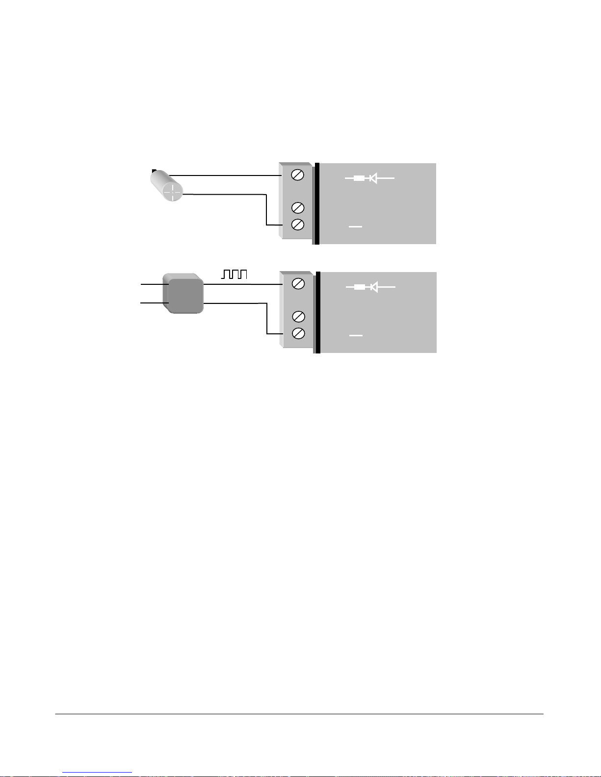
2.4.6 Pulse Input (905-1)
For the ”-1” module, digital input 1 may be configured as a pulse input (max rate 100 Hz, min. off
time 5 ms). In this mode, both the pulse rate and the pulse count are available for mapping to a remote
output. The pulse rate may appear at any analog output on the remote unit, while the pulse count can
appear at a Pulse Output on another ”-1” or Digital/Pulse Output on a ”-3” or “-4” unit. The pul se i nput
should be connected in the same way as a digital input.
Active pulse signals can be connected directly provided the peak voltage is between 3.5–13V and the
low voltage is less than 1.5V. Note that the 905U will ground the negative of the pulse signal. If the
voltages are not compatible, use a solid state relay to isolate the two devices.
2.4.7 Pulse Inputs (905-2 and 905-4)
For the ”-2” and ”-4” modules, the four digital inputs (DI 1-4) may be configured as pulse inputs. The
first digital/pulse input DI 1 has a maximum rate of 1000 Hz (min. off time 0.5 ms), while DI 2-4
have a maximum rate of 100 Hz (min. off time 5 ms). When using DI 1 at high pulse rates (more than
100 Hz), a divide by 10 function may be configured to reduce the pulse count at the output, as Pulse
Outputs have a maximum rate of 100 Hz.
For each pulse input, both the pulse rate and the pulse count are available for mapping to a remote
output. The pulse rate may appear at any analog output on the remote unit, while the pulse count can
appear at a Pulse Output. The default update time for pulse counts is 1 minute. This can be changed
by changing the update time configuration - refer Chapter 4 Configuration for further details. The
pulse count is a 16 bit value - “roll over” of the count when it exceeds the maximum value is
automatically handled by the modules.
+
_
DI 1
COM
905U
Passive
transistor
device
+
_
+
_
DI 1
COM
905U
External
power
supply
+
_
Active pulse device
Note:
Use a solid
state relay if
the voltage
range is not
suitable.
905U Wireless I/O Module User Manual
105S Serial I/O Module
Page 24 © January 2011
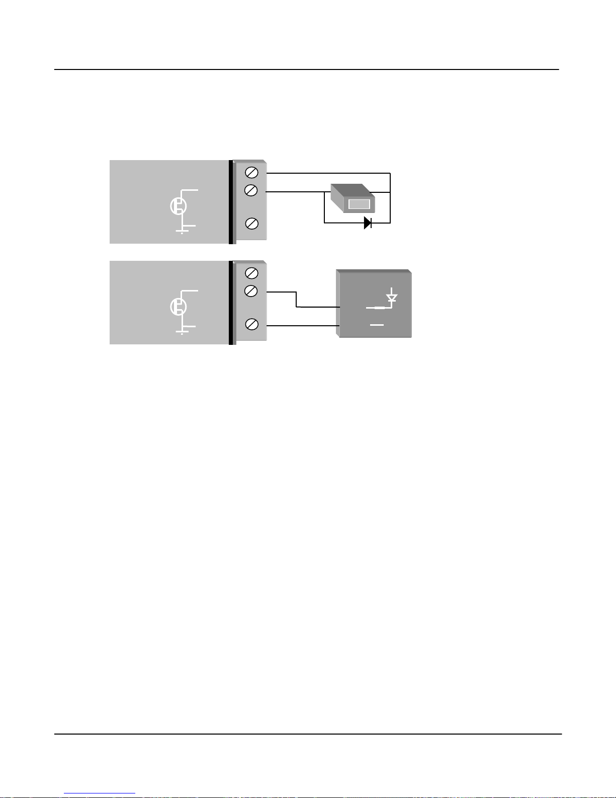
2.4.8 Pulse Output (905-1)
A single FET output to common rated at 30VDC, 500 mA is provide for the pulse output "PO". This
output accurately recreates the pulses counted at a pulse input at another module.
If the counter device requires a voltage pulse signal (such as electronic or elector-mechanical counters),
use the 24V analog loop supply, or the 12V BAT supply for the voltage source. Use a by-pass diode if
the counter is inductive.
Some devices such as PLC counter modules power the pulse loop. For these devices, connect to the
PO and COM terminals of the 905U. The COM terminal will connect a ground/earth to the external
device. If this is not suitable, use a solid state relay to isolate the external device.
Although the count is accurately re-created, the rate of output pulses may not accurately reflect the
input rate. The actual input pulse rate may be configured to appear at an analog output if required.
Note that the pulse rate and accumulated value will remain accurate even if a period of
communications failure has occurred. The maximum output rate is 100 Hz.
2.4.9 Pulse Output (905-3 and 905-4)
The first four digital outputs on the ”-3” and ”-4” modules may also be used as pulse outputs. The
outputs are FET output to common rated at 30VDC, 500 mA. The outputs will provide a pulse signal
of up to 100 Hz. The outputs accurately recreate the pulses counted at pulse inputs at a ”-1”, ”-2” or
“-4” module.
Although the count is accurately re-created, the rate of output pulses may not accurately reflect the
input rate. The actual input pulse rate may be configured to appear at an analog output if required.
Note that the pulse rate and accumulated value will remain accurate even if a period of
communications failure has occurred.
_
+
+24V
PO
COM
905U
Use by-pass
diode if counter
is inductive.
COUNT
+
_
+
_
+24V
PO
COM
905U
Use solid-state
relay isolator if
voltages are not
compatible
Chapter Two Installation
man_905-105_2.16 Page 25
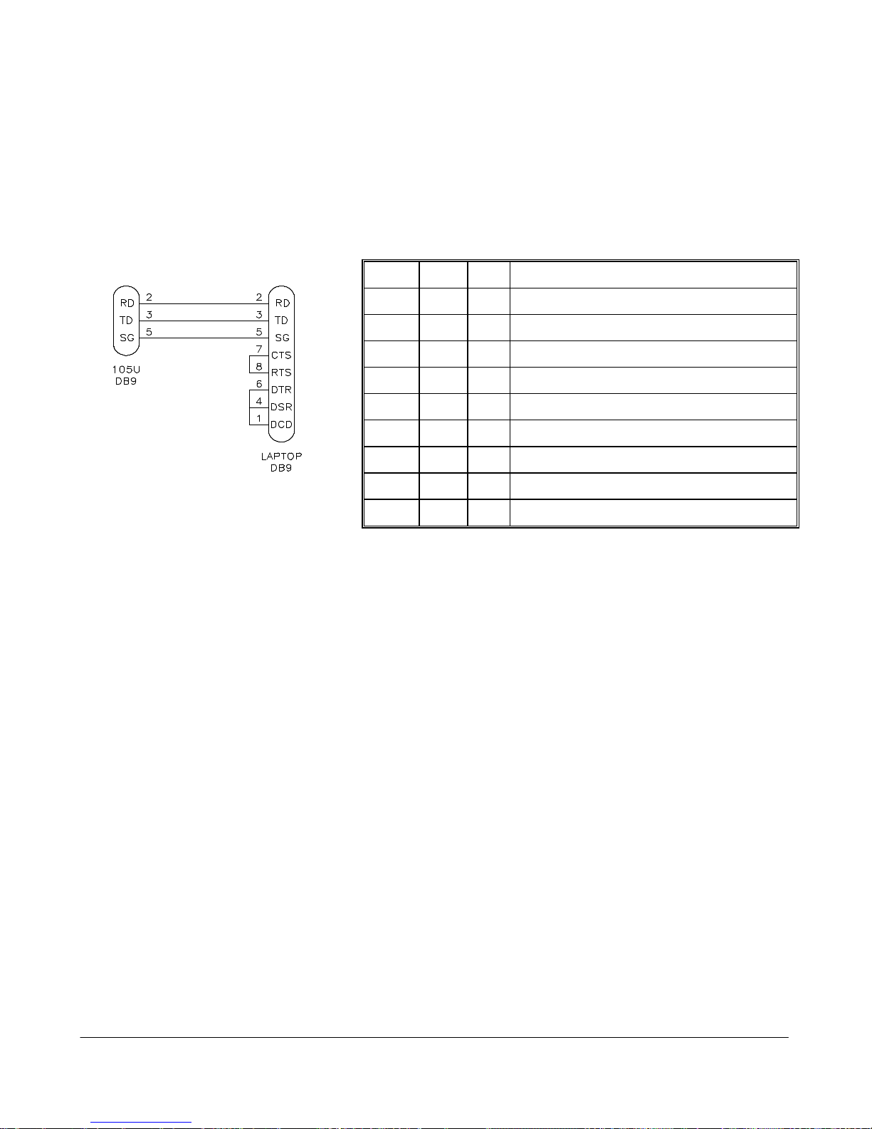
2.4.10 RS232 Serial Port
The serial port is a 9 pin DB9 female and provides for connection to a terminal or to a PC for
configuration, field testing and for factory testing. This port is internally shared with the RS485 ensure that the RS485 is disconnected before attempting to use t he RS232 port. Communication is via
standard RS-232 signals. The 905U/105S is configured as DCE equipment with the pin-out detailed
below. The serial port communicates at a baud rate of 9600 baud, 8 bits, no parity, one stop bit. An
example cable drawing for connection to a laptop is detailed below:
MALE FEMALE
Pin Name Dirn Function
1 DCD Out Data carrier detect - not used
2 RD Out Transmit Data - Serial Data Input (High = 0, Low = 1)
3 TD In Receive Data - Serial Data Output (High = 0, Low = 1)
4 DTR In Data Terminal Ready - not used
5 SG - Signal Ground
6 DSR Out Data Set R eady - not used
7 RTS In Request to Send - not used
8 CTS Out Clear to send - not used
9 RI - Ring indicator - not used.
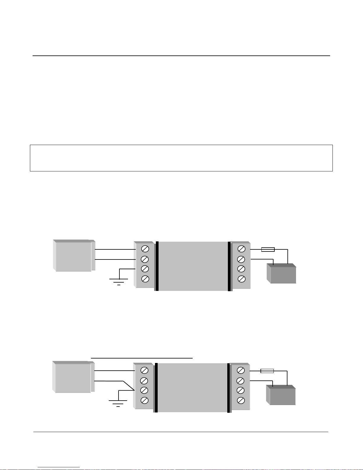
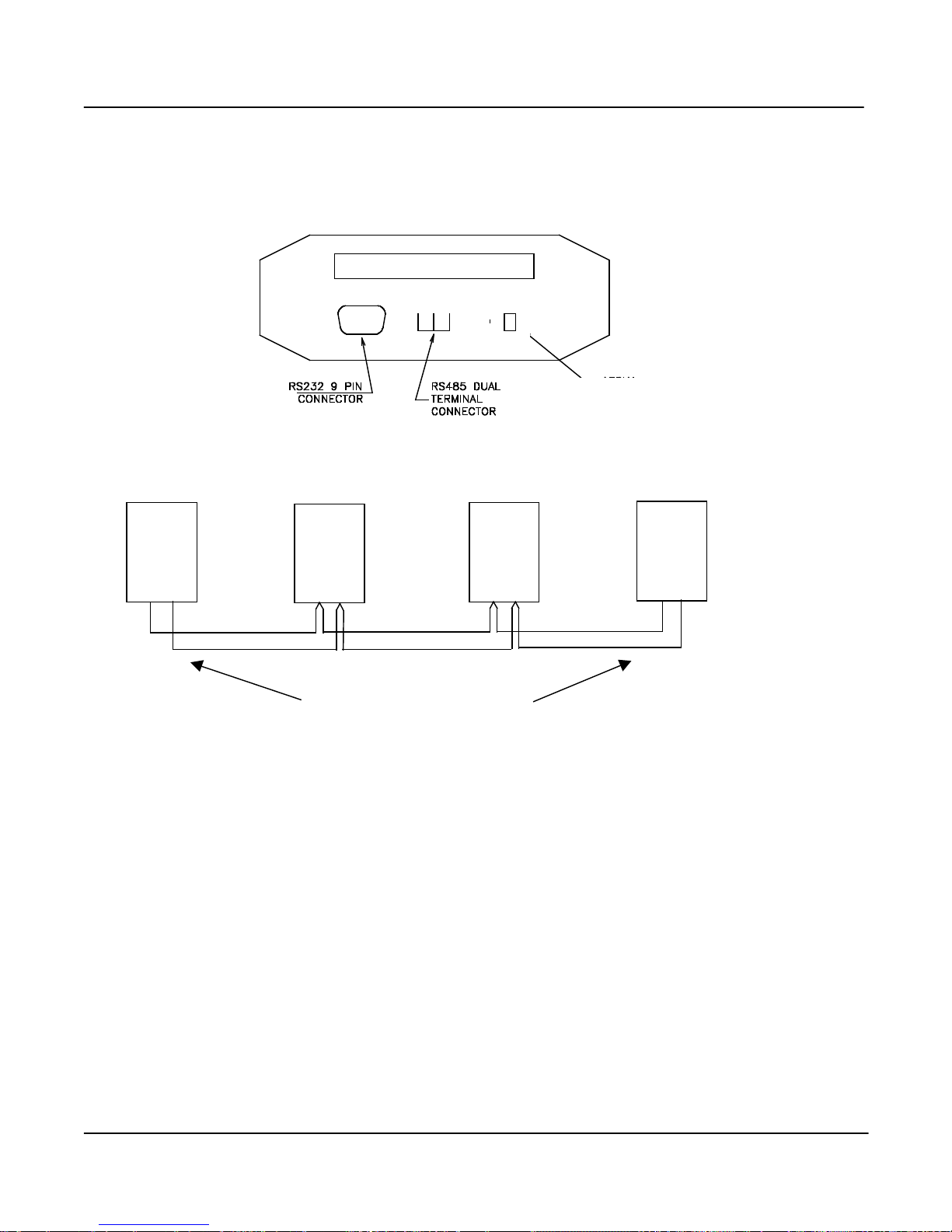
2.4.11 RS485 Serial Port
The RS485 port provides for communication between multiple units using a multi-drop cable. Up to 32
units may be connected in each multi-drop network. Each multi-drop network may have one unit
providing radio communications with other units in the system. The RS485 feature allows local hubs of
control to operate without occupying radio bandwidth required for communication between remotely
sited units.
The RS485 Communications format is 9600 baud, 8 data bits, one stop bit, no parity. Note that the
RS485 port is shared internally with the RS232 port - di sconnect the RS232 cabl e after configurati on is
complete.
RS485 is a balanced, differential standard but it is recommended that shielded, twist ed pair cable be
used to interconnect modules to reduce potential Radio Frequency Interference (RFI). An RS485
network should be wired as indicated in the diagram below and terminated at each end of the network
with a 120 ohm resistor.
905U Wireless I/O Module User Manual
105S Serial I/O Module
Page 26 © January 2011
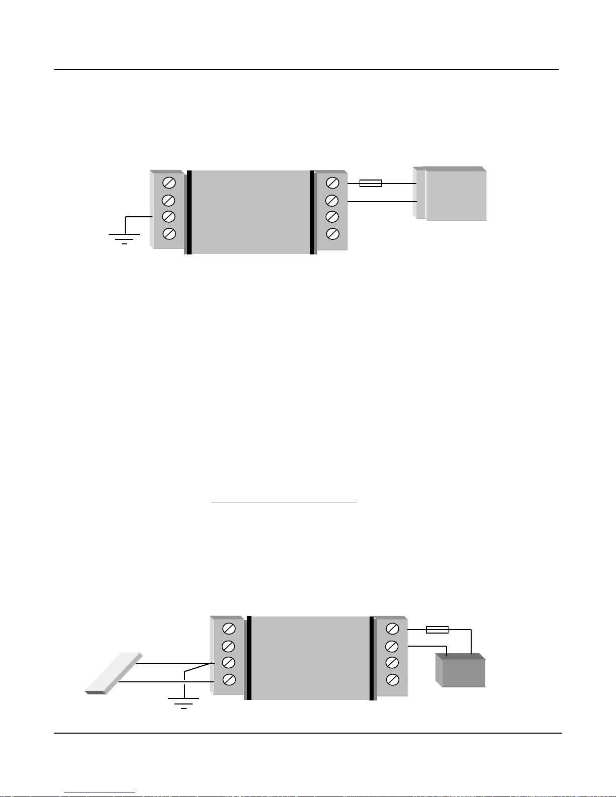
The modules include a terminating resistor on-board. If the 905U module is the first or last module in
the RS485 chain, then the terminating resis tor may be connected by operat ing the single DIP switch i n
the end-plate next to the RS485 terminals. “On” or “down” means that the resistor is connected.
2.4.12 Connecting 105S Modules to 905U Modules
105S modules connect to a 905U via the RS485 port on each module - refer to section 2.4.11. Up to
31 x 105S modules can be connected to a 905U module. This number is reduced for 105S-3 and –4
modules, as these modules use two unit addresses (refer to chapter 4 of this manual).
The 105S modules can be mounted next to the 905U module, or they can be remote from the 905U.
The reliable distance for a RS485 multi-drop line depends on the shielding of the wire and how close it
is installed to electrical noise sources - distances of more than ½ mile (1 km) can be achieved by good
installation methods. External RS485 isolators are recommended if the earth potential difference
between modules is greater than 7V.
A B
TERMINATING
RESISTOR SWITCH
905U
105S
RS485
A B
905U
105S
RS485
A B
905U
105S
RS485
A B
905U
105S
RS485
A B
Activate resi stor - c onnec tion
switch at both end modul es
 Loading...