

Page 1

Alert Tag Instruction Manual and Spec -Sheet
FCC Co mpli ance
The FCC W ant s You to Kno w
This equipment has bee n test ed and found to c omply with the limits
for a Class B digital device, pursuant t o Part 15 of the FCC rules.
These limits are desig ned to provide reasonable protect ion agai nst
harmful interference in a residential installation. This equipment
generates, uses and can radiate radio f requency energy a nd, if not
installed and used in accordance with the instructions, may cause
harmful interference to radio communicatio ns. However, t here is no
guara ntee that inter fe rence w ill not oc c ur in a par tic ular i nst al latio n.
If this equipment does cause harmful interference to radio or
television reception, which can be determined by tuning the
equipment off and on, the user is enco uraged t o try to correct the
interfer ence by one or more of the followi ng measures:
a) Reorient or relocat e the receiving ante nna.
b) Increase the separation between the equipment
and receiver.
c) Connect the equipment to an outlet on a circuit
different from that to which the receiver is
connected.
d) Consult the dealer or an experienced radio/TV
technician.
FCC Wa r ning
Modificatio ns not expressly approved by manufact urer could void
the us er aut hority t o oper at e the equipment under FCC rules.
15.9 (a) Labeling Requirements
This device complies with Part 15 of the FCC Rules. Operation is subject to the
following two conditions. (1) This device may not cause harmful interference, and (2)
this device must accept any interference received, including interference that may
cause undesired operation.
Page 2
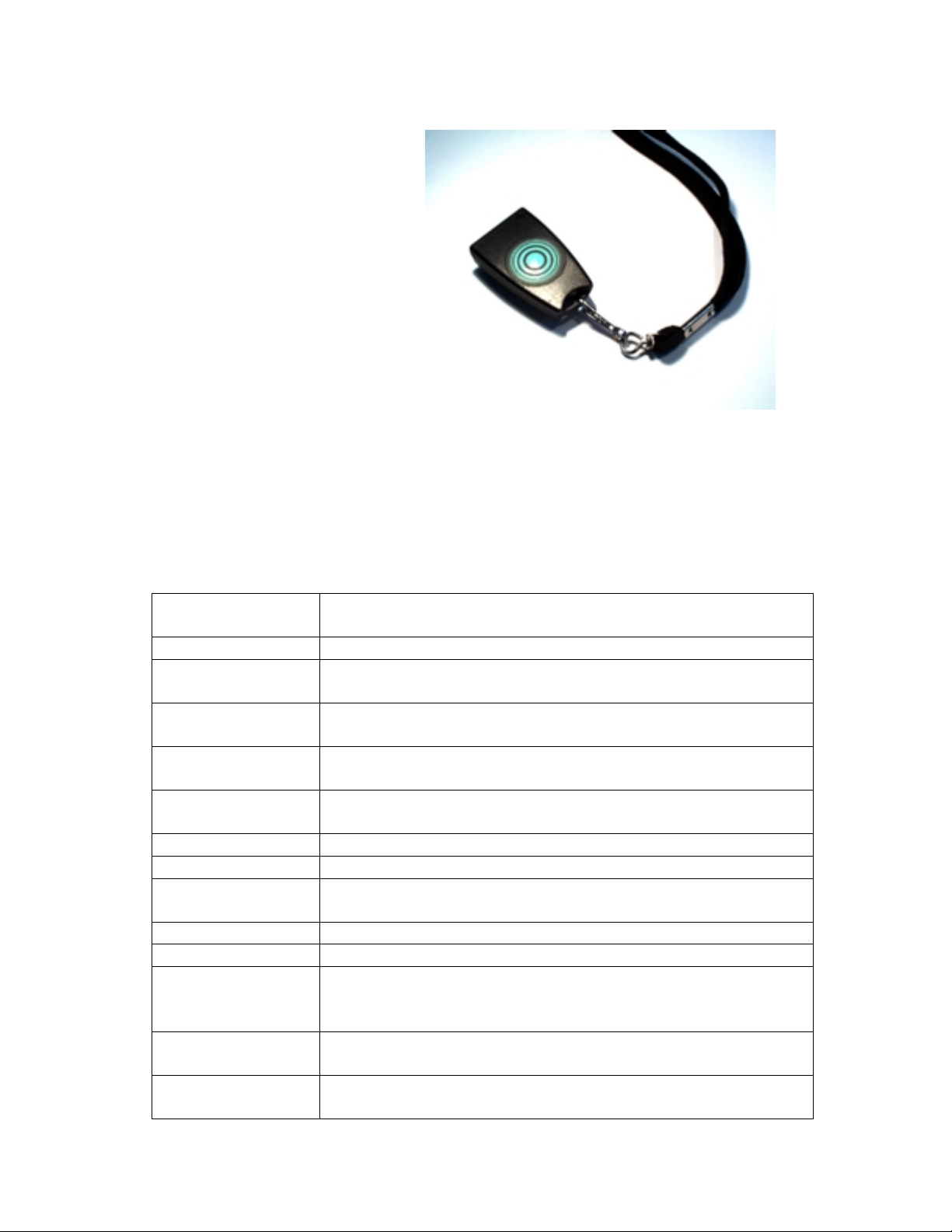
IR and RF Alert Tag
P/N: ALB00001 (433.92 MHz)
Feirm ware ver2
IR/RF Alert Tag
Description
A small light-weight, oval badge. The tag sends Infra Red signals, and in addition
sends RF signals in the frequency of 433.92 MHz. Designed especially for the
convenience of the elderly or persons in stressful situations (ale rt, pan ic, etc.).
General
Elect rical p ower
source
Data rate
Modulation
Message
protocol
Message
duration
Button on badge
Battery type
Battery life
Battery statu s
indication
Badge ID
Dimensions
Weight
(including
battery)
Temperature:
Operating
Temperature:
Storage
One 3 - Volt lithium battery
19,200 bits per sec ond
ASK
(Amplitude Shift Keying of IR or RF carrier)
4 by tes proprietar y format
2.08 ms
Location d epend ent funct ion.
Button press message transmitted on IR.
CR 2032 Renata
One year, assuming movement 8 hr / day
Battery status transmitted with every RF and IR message
Uni que fa c t o r y progr amm ed
Pen dant sh ape 55 x 35 x 18 mm
25 gr am
-10 to 70°C
-20 to 60°C
Page 3

Humidity:
Operating
Humi dity :
Storage
Accessories
IR Transmission
Operating – 5 to 95% RH @ 70°C
Non Oper ating ( 12 Hours ) – 5 to 95% RH @ 85°C
Neck strap (included)
Peak optical
transmitted
power
Peak
transmission
wavelength
Peak radiant
intensity
Frequency of
transmission
Transmission
rate
Transmission
angle
RF T ransmissi on
Modulation
Transmission
rate
Average ERP
Effective
Radi at ed Power
Stability
Peak ERP
Transmission
pattern
500mW
880nm
120 mW/Sr
Carrier at 455 K Hz
Motion – every 10 sec m es sage
Moti onless – every 60 sec message.
360° badg e plane. ±60° to badge per pend ic ular axis
433.92 MHz
ASK
(Amplitude Shift Key ing of 433.92 MHz carrier)
Every 10 sec message.
- 70 dbm max
+/- 20ppm
-20 dbm (max)
Omnidirectional
Page 4

Using the Alert Tag
The following is a set of procedures to ensure proper use of the Alert Tag.
To use the Alert Tag:
1. For general use, place the strap of the Alert Tag around the person’s neck.
2. In case of emergency press the large press button.
Battery Replacement
The battery is located inside the Alert Tag. In order to replace the battery, you need
to open the back side of the Alert Tag with a Phillips screwdriver (preferably an
electric one) with point size "0". For exa mple, the APEX #4910. A new battery can
then be inserted, after which the screw must be replaced.
 Loading...