

Page 1
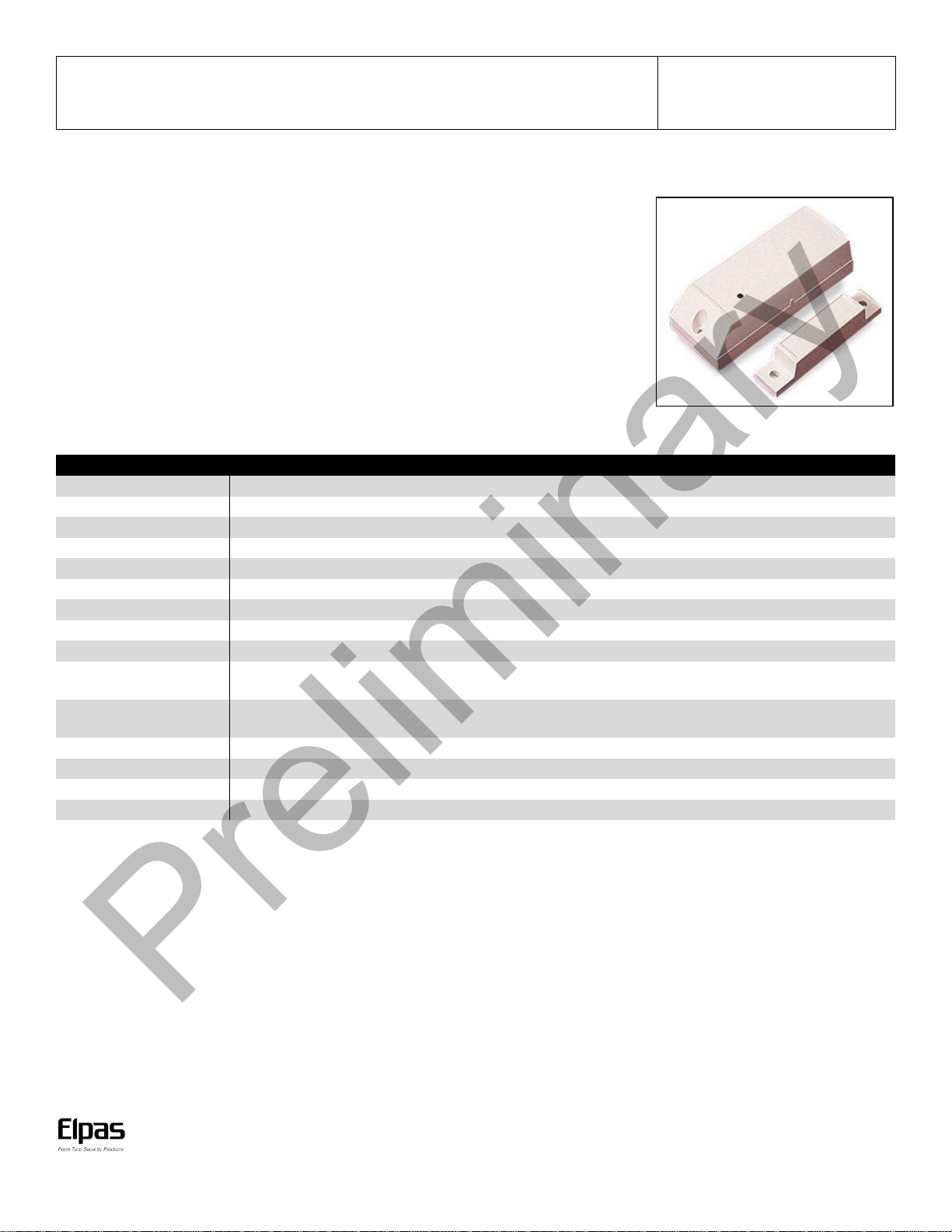
Elpas Wireless Magnetic Contact
P/N: 5-MAG00433
Install Guide
www.elpas.com
Page 1 of 4
V3/April 2013
Signaling Technologies
RF (433MHz)
Transmission Rate
Every 120 seconds
Alarm Inputs
1 magnetic reed switch, 1 auxiliary input
Supervised Events
Low Battery, Tamper
Power Source
3.6V/1.2Ah Lithium Battery (Type LiSOCl2)
Average Battery Life
3 years
LED Indicator
TBD
Tag ID
Unique, factory-programmed ID
Construction
White Nylon Plastic
Dimensions (H x W x D)
Transmitter: 81 x 30 x 23 mm (3-3/16 x 1-3/16 x 15/16 in.)
Magnet: 63x13x13 mm (2-1/2 x 1/2 x 1/2 in.)
Weight
Transmitter: 34 grams (1.2 ounces)
Magnet: 13 grams (0.45 ounces)
Operating Environment
Temp: -20°C to 70°C (-4°F to 159°F) Humidity: 90% non-condensing
Remote Management
Eiris 4.8 (or higher) Elpas Configurator 4.8 (or higher) ELC Programmer V2.0
Standards
IC, FCC & CE compliant
Warranty
1 year limited (excluding battery)
Preliminary
Description
The Elpas Magnetic Contact is a battery operated; wireless universal door contact designed for use in
Elpas Safety, Security and Visibility solutions. The device can be mounted anywhere to secure door and
window openings. The transmitter emits EMI safe 433MHz RF messages that enables the reporting a
monitoring of ‘State’ changes from one dry contact input to be sent via the Elpas Ethernet RTLS
infrastructure to a host Elpas RTLS application or to other management monitoring solutions.
The Magnetic Contact provides a single zone of protection, and installs easily on doors or windows with
the included mounting hardware or double-sided The contact has three unique input loops (zones )The
first loop (primary loop) is supervised and typically used for high-priority alarm reporting such as
commercial fire or burglary. The second loop is the built-in, normally closed reed switch used in
conjunction with magnet; the third loop is another normally closed household burglary loop.
Product Specifications
Product offerings and specifications are subject to change without notice.
Page 2
Elpas Wireless Magnetic Contact – Installation Guide
www.elpas.com
Page 2 of 4
V3/April 2013
IMPORTANT: Inserting the 3.6V/1.2Ah battery improperly into
the battery clip may cause damage to the Magnetic Contact.
Preliminary
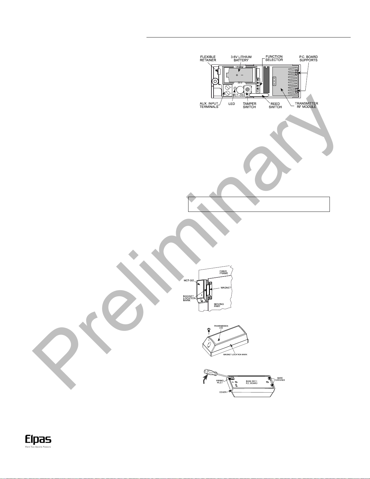
Aux Inputs Interface
The Magnetic Contact contains aux input terminals for
connecting two analog alert monitoring inputs.
Tamper Switch
The Magnetic Contact contains a spring loaded tamper switch
that when pressed, generates a ‘State’ message that is useful for
registering the monitoring point in the host application
Once registered, the tamper switch can also be used as an input
trigger for a device supervision tamper alert indicating nonauthorized attempts to remove the device’s cover.
Power
The Magnetic Contact derives its power from one CR2430 type
lithium battery (factory supplied) or alternatively from a single
1/2AA battery.
IMPORTANT: The Wireless Input Module as well as all the input devices
to be monitored should be powered down when wiring in order to prevent
accidental shorts/spikes to cause damage to any of the devices.
Status Indicator
The Magnetic Contact has a Red Status LED that flashes
once/second signaling either a low voltage condition or that the
device is transmitting.
Lithium Battery Installation (supplied with device)
Before inserting the CR2430 type lithium battery into the
module’s battery holder, confirm that the holes of the battery
Isolator are aligned with the contact pins. Then ensure that the
positive (+) side of the battery faces the PCB.
Supported Event Transmissions
The Magnetic Contact can transmit state changes from up to two dry
contact inputs (as a button press event message) to the host RTLS server.
Input 1 – Button 1 Event
Input 2 – Button 2 Event
The Magnetic Contact can also transmit a state change from the tamper
switch (as a motion event message) indicating a non-authorized attempt to
remove the module’s cover.
Tamper Switch – Motion Event
Note: Whenever a state change is detected the input module
automatically transmits 4 RF event messages 400ms apart with each
transmission about 2ms in duration).
Installation Mounting
Attach the Magnetic Contact to the fixed frame and the magnet to
the movable part (door or window), as shown below. Make sure
that the magnet is located not more than 6mm (0.25 in) from the
transmitter’s marked side .
Step 1: Remove the case closure screw
Step 2: Remove the unit’s cover
Step 3: Flex out the circuit board retainer and detach the circuit board
from the base.
Page 3

Elpas Wireless Magnetic Contact – Installation Guide
www.elpas.com
Page 3 of 4
V3/April 2013
Switch
Function
Selector
Selected Option
Default
SW1
Reed switch input
Determines whether the reed switch input will be
active or inactive
Note: With SW-1 set to OFF, the auxiliary input will
not initiate periodic supervision transmissions.
ON
Reed switch input is enabled
ON
Off
Reed switch input is disabled
SW2
Aux. input
type selector
Determines whether the auxiliary input will behave as
-of-line (E.O.L.) input or as a normally
closed (N.C.) input.
ON
OFF
OFF
Aux. input is N.C.
SW3
Restore reports
Determines whether the transmitter will report a
restore event when an input restores from an alarm
condition.
Selecting the ON position enables you to find out
whether the door or window under surveillance are
open or closed.
ON
Restore events reported
ON
OFF
Restore events not reported
SW4
Transmit Mode
In non-supervised systems, it is sometimes
required to report an alarm repeatedly at short
intervals, until the disturbed input reverts to its
normal (undisturbed) state. SW-4 is used to select
between repetitive and one-shot transmission.
Note: Transmissions initiated by “tamper” events
will be repeated once every 3 minutes, regardless
of SW-4 setting.When done, Install the battery as
directed in Para. 4.2.
ON
Reports alarms every 3 min.
OFF
OFF
Reports alarms only once
Preliminary
Step 6: Mount the magnet near the marked side of reed switch.
Step 7: Insert the edge of the circuit board with the RF module into the
edge supports and press the other edge against the flexible retainer until it
snaps home with a click
Step 4: Hold the base against the mounting surface and mark the
drilling points through the mounting holes
Step 5: Drill the holes and fix the base to the wall using the 2 screws
with countersunk heads supplied in the package.
Preparation for Use
The Magnetic Contact is equipped with a 4-position DIP switch Each switch lever enables selecting 1 of 2 options.
B. Setting the Switches
Set the function switches as desired prior to applying power.
Use a ball point pen or another pointed object to shift the switch levers. The ON position is indicated by the arrow on the switch body .
Table 1. Getting acquainted with the function selector
Page 4

Elpas Wireless Magnetic Contact – Installation Guide
Page 4 of 4
V3/April 2013
W.E.E.E. Product Recycling Declaration
For information regarding the recycling of this product you must contact the company from which you orignially purchased it.
If you are discarding this product and not returning it for repair then you must ensure that it is returned as identified by your supplier.
This product is not to be thrown away with everyday waste - Directive 2002/96/EC Waste Electrical and Electronic Equipment.
FCC & IC Compliance Standards
Th is device (F CC ID#: O4X5 -MAG00 433 and IC ID#: 1467 G-5MAG 0043 3)
co mpli es with FC C Rules Part 15 and with I ndus try Cana da l icen se exempt RSS standa rd(s). Op era tion is sub ject to two co nditio ns: (1 ) This
de vice m ay not cause h armf ul interf eren ce, a nd (2) thi s de vice m ust
ac cept any i nter fer ence tha t may be r ecei ved or th at m ay ca use un desi red
op eratio n.
Fo r In dustry Canad a: Le prése nt app areil est co nfor me aux CNR
d' Indu str ie Canad a a ppl icab les a ux appar eils radi o e xempts de licen ce.
L' expl oitati on es t au tor isée a ux deux c ondi tions su ivan tes : (1) l'ap pareil
ne do it pa s p rodu ire d e b roui llage, et (2) l' uti li sat eur de l'ap pare il do it
ac cept er tout br ouil lage radio élec tri que subi, même si le br oui ll age es t
su scep tib le d 'en co mpro mettre le fo ncti onn emen t.
No te: This e qui pmen t has b een test ed a nd foun d to c omply wi th t he l imits
fo r a Clas s B di gital de vice , pur suan t to part 1 5 of the FC C Rule s. T hese
limits ar e d esig ned to pr ovi de rea son able prot ecti on again st har mful
inter fer ence in a re side nti al inst allatio n. Thi s eq uipmen t ge nerate s; us es
an d ca n ra diat e ra dio fr eque ncy ene rgy and, if not in stalle d an d us ed i n
ac cord anc e with t he in stru cti ons, m ay c ause har mful i nte rfer ence to ra dio
co mmunic atio ns.
Ho wever, there i s no gua rantee t hat i nterfe ren ce wi ll not occ ur i n a
pa rtic ular i nstall atio n.
If th is equip ment do es cau se h armful in terfer ence to radio or te levi sion
re ceptio n, whic h ca n be dete rmin ed by tur ning th e equi pmen t of f an d on , th e
us er is enco urag ed to try t o c orrect the i nter ferenc e b y one or mo re of the
fo llowin g mea sure s:
Re ori ent or r elo cate th e re ceivin g an ten na .
In cre ase the se parati on b etween the e quip men t an d rece iver .
Co nne ct t he equ ipme nt into an out let on a ci rcui t differ ent fr om tha t to
wh ich the rec eiver is c onn ecte d.
Co nsult the de aler or an experi enced radi o/T V te chnici an for hel p
Ch ange s o r modi ficati ons to this eq uipmen t not ex pre ssly ap prov ed b y t he
pa rt y r es pons ib le fo r c om plia nc e (E lp as Sol ut io ns Lt d. ) c oul d v oi d th e us er ’s
au thorit y to opera te the equip ment .
Th is equip ment co mpl ies with FC C a nd IC RF ra diatio n e xpos ure li mi ts set
fo rth for an unco ntroll ed env iron men t.
Company Contact
El pas, In c.
Westf ord, M as sach uset ts (US A)
Te l: 1 -800-223-0 020
Preliminary
EU Declaration of Conformity
Th is e qui pmen t is i n co mpl ianc e with the e ssen tial requ irem ents a nd o ther r elevan t prov isio ns of D irecti ve 1 999/5/ EC
Product Warranty
El pa s S ol ut io ns , L td . ( th e C om pa ny) , a nd it s a ff il iat es , w ar ra nt s i ts pr od uct s (h er ei na ft er r ef er re d t o a s " th e P ro du ct ”) t o b e f ree of de fe ct s i n m ater ia ls and wo rkm an sh ip un der no rm al
op er at in g co nd it ion s an d us e fo r a pe ri od o f on e ye ar f ro m th e da te o f sh ip me nt b y El pa s. T he C om pa ny ’s o bl iga ti on s sh al l be li mi te d with in t he w ar ra nty pe ri od, at i ts op ti on , to r ep air or t o
re pl ac e the d ef ec ti ve Pr od uc t o r an y def ec ti ve c ompo nen t or p art t he re of . T o ex er ci se th is war ra nty , th e prod uct m us t be re tu rn ed to th e m a nu fa ctu re r fr eigh t pre pa id and i nsu re d.
Th is warr ant y d oe s no t a ppl y t o rep air s o r rep lace me nt c au se d by im pro pe r ins tal la ti on , Pr o du ct m is us e, f ai lu re t o f ollo w in st al la tion or op er ati ng in str uc ti on s, a lt er ati on , a bus e, ac cid en t,
ta mp er in g, r ep air by a ny on e ot he r th an E lp as , ex te rn al c au se s, an d fa il ur e to per fo rm req ui re d pr ev en tive m ai nt en anc e. T hi s w ar ra nt y al so does n ot app ly to any pr od uc ts , ac ce ss ori es , or
at ta ch ment s u se d i n co nj un ct io n w it h t he Pr od uct , i ncl ud in g b at te ries , w hi ch sh al l b e c ov er ed sol ely b y t he ir own wa rr ant ie s, i f a ny. E lpas sh al l n ot be lia bl e f or an y d am ag e o r l os s
wh at so ev er, w het he r di re ct ly , i nd ir ectl y, inc identa ll y, co ns equ en ti al ly or o ther wi se, r es ult in g f rom a ma lf unct io n o f the Pr od uc t d ue to p rodu ct s, a cc esso rie s, or at ta c hm ents of o the rs ,
inc lud in g batt er ie s, us ed i n c on ju nc tion wi th the Prod uct .
EL PA S MA KE S NO EX PRE SS WA RRA NT IE S EX CE PT T HO SE STA TE D I N TH IS S TA TE ME NT. EL PAS DI SC LA IMS AL L O THE R W ARRA NTI ES , E XPR ES S OR IMP LI ED , INC LUDI NG W IT HO UT
LI MI TA TI ON IM PL IE D W AR RA NT IE S O F M ER CH AN TA BI LI TY AN D F IT NES S F OR A PA RT IC ULA R PU RP OS E. EL PA S’ S S OL E R ES PON SI BI LI TY FO R W AR RA NT Y C LAI MS IS LI MI TE D T O
RE PA IR OR TO RE PL AC E AS SE T FO RTH I N THIS STA TE MEN T.
El pa s sh al l have n o li abil it y fo r any de at h, p er so nal i nj ur y, p ro pert y dama ge , or o the r lo ss w he th er di re ct , in di rec t, i nc id e nt al, co nseq ue nti al , or o th er wise , ba sed on a c la im t ha t the P ro du ct
f ail ed to f un ct io n. H ow ever , if El pas i s h el d li ab le, wh ethe r di re ctly o r i ndi re ct ly , fo r an y l oss or da ma ge a ri sin g u nde r t hi s li mi ted wa rr anty o r oth er wi se , re ga rdle ss of ca use or o ri gi n, th e
co mp an y' s maxi mu m li abi li ty s ha ll b e li mi ted to t he p ur ch ase pr ic e of t he P ro du ct, wh ic h sh al l be f ix ed a s li quid at ed d am ag es a nd n ot a s a pe na lty, a nd s ha ll b e th e co mp lete a nd e xc lu siv e
lia bil it y of E lpa s.
El pa s sh all n ot , un de r an y cir cu ms ta nces w hat so ev er , be li ab le f or any i nac cu ra cy, er ro r of j udgm ent, d ef aul t, o r ne gli ge nc e o f Elpa s, it s em pl oy ees , of fi cers , age nt s, o r any o th er p art y, o r of
th e pur ch ase r o r us er , ar is in g fr om a ny ass is ta nc e or com mu ni cat ion of a ny k in d r ega rd in g th e con fi gur at io n, de sig n, inst alla t ion, o r cre at io n of sec ur it y sy st em i nv ol vi ng t he P ro du ct, th at
bein g th e re sp on si bil it y of the pur ch as er o r us er . If E lp as i s un ab le t o ma ke s uc h re pa ir o r re pl ace me nt , th e co mp an y’ s en ti re l ia bili ty s hall b e li mi te d to t he c os t of a re aso na bl e su bs ti tut e
pr od uc t. E lp as sh al l not b e re sp ons ib le f or a ny di sm an tlin g, ins ta ll at ion, r ein st al la tion , pu rc has in g, s hippin g, ins ur anc e, o r any s im il ar ch ar ge s.
El pa s sh al l h av e no l iabi li ty f or an y d am ag es, i nc lu di ng wi th ou t l im it at ion , a ny d ir ect , i ndi re ct , i nc id enta l, sp ec ial, or c ons eque nti al d amag es, e xpen se s, c ost s, p rofi ts , l os t sav in gs o r
ea rn in gs, or ot he r da ma ges a ri si ng o ut of t he u se o f th e P ro du ct o r the re mov al , in st al lat io n, r ei nst al la ti on, rep ai r or r epl ac emen t of t he Pr od uc t or a ny r el ate d ev en ts. In t he e ve nt t hat th er e
is any l ia bi li ty ag ai nst E lp as , suc h li ab il ity sha ll b e li mi te d t o th e pur ch as e pr ic e of t he Pr od uct w hi ch am ou nt s ha ll b e f ix ed a s l iq ui da ted dama ge s.
Th e pu rc ha se r an d us er u nder st and th at t hi s Pr od uct may be c om pr omis ed o r ci rc um ve nt ed by inte ntio na l ac ts; th at t he P ro duc t wi ll not in a ll c as es p re ve nt d ea th, pers on al i njur y, p rope rty
da ma ge , or o th er l os s re su lt in g fr om b ur gl ary , ro bb er y, f ir e or othe r ca us es; an d th at t he P ro du ct w ill no t i n al l ca se s pr ov i de a dequ at e wa rnin g or pr otec ti on. Th e pu rc has er a nd use r als o
un de rs ta nd t hat a pr op erl y i nsta ll ed and m ai ntai ne d al arm ma y re duc e t he ri sk of e ve nt s such a s bu rg lar y, r ob be ry , an d fi re wi tho ut w arn in g, b ut i t is n ot in su ra nce or a g ua ran te e th at s uc h
ev en ts wi ll n ot o cc ur or t hat th ere w il l be n o de at h, pe rs on al in ju ry , pro pe rt y dam ag e, o r o th er l os s as a re su lt of su ch ev en ts .
By p urc ha si ng th e P ro du ct, t he p ur chas er an d u se r s ha ll de fe nd, i nd emni fy an d h ol d E lp as, i ts of fi ce rs, dir ec tors , a ff il ia tes , su bs id ia ries , a ge nt s, s erv an ts , em pl oy ee s, a nd a ut hori ze d
re pr es enta tive s ha rm le ss f rom and ag ai ns t an y an d al l cl ai ms , su it s, c osts , da ma ges, a nd j ud gm ent s inc urr ed , cl ai me d, o r su st ai ned whe th er f or d ea th , pe rs ona l i njur y, p ro per ty da mage , or
ot he rw is e, be ca us e of or in a ny w ay r el ate d to t he c onfi gu rat io n, d es ign, i nsta ll ati on , or c re ati on o f a s ec uri ty s ys tem in vo lv ing t he P ro duct , an d th e use, s al e, di st ri bu ti on, a nd i ns tal la ti on o f
th e Pr od uc t, i nc lu di ng p aym en t of a ny an d al l att or ne y’ s f ee s, c ost s, a nd e xp en ses i nc urr ed a s a re su lt o f any s uc h ev ent s.
Th e pu rc ha ser o r us er s ho ul d f ol lo w th e Pr od uct i ns ta ll ati on a nd o per at io n in str uc ti on s and te st the P ro du ct an d th e en tir e sy st em a t le ast o nc e eac h we ek . For va r ious r ea son s, i nc lud in g bu t
no t li mi te d to c ha nge s in e nv ir on men ta l co nd itio ns, el ec tric , el ectr on ic, or el ec tr om agne ti c di sru pt io ns, a nd t am pe ri ng, t he P ro du ct m ay n ot p er fo rm a s ex pe cted . Th e pu rch as er a nd u ser ar e
ad vi se d to ta ke a ll n eces sary p rec au ti on s f or t he pro tect io n an d saf et y of pe rs on s an d p ro pe rt y.
Th is st at em ent p ro vi de s c ert ai n l eg al ri gh ts. O th er ri gh ts ma y v ar y b y s t at e o r c ou ntr y. Und er ce rt ai n c ir cum st an ce s, s ome s ta te s o r c ou ntri es ma y n ot al lo w e xclu sion or li mi ta tion of
inc ide nt al o r c on se qu ent ia l da mage s or im pl ie d war ra nt ie s, so t he a bo ve e xc lusi ons ma y n ot a ppl y un de r t ho se c ir cum st an ce s an d i n th os e sta te s or co un tr ie s.
El pa s re se rv es th e ri gh t to m od if y th is st at em en t at a ny t im e, in it s sol e di sc re tion w it ho ut no ti ce t o an y pu rch as er o r us er . H owe ve r, t hi s sta te me nt s hal l no t be m od if ie d or v arie d ex cep t by
El pa s in w ri ti ng, an d El pas do es n ot a ut ho ri ze any s in gl e in divi du al t o ac t on i ts b eh alf to m od if y or v ar y thi s st at em ent . Any q ue st i on s about th is s ta teme nt
sh ou ld be di rec te d to Elp as.
 Loading...