

Page 1
www.elpas.com
Page 1 of 7
V22/Jan 2013
Elpas LF BUS Beacon
For P/Ns: 5-ALA00125-11, 5-ALA00125-12 & 5-ALA00125-2
Installation Guide
Product Description
The Elpas LF BUS Beacon is a fully supervised, 125KHz
emitter that adds instantaneous location (choke-point)
awareness to RTLS security and safety applications
The LF BUS Beacon generates a user-adjustable, spherical
shaped electromagnetic field up to 1.5m/5ft in radius that can
be used to cover a single interior doorway. Optionally, up to
four LF BUS Beacons can be deployed in ‘Primary–Secondary’
star or daisy-chain topologies to cover large double-doors or
architectural complex indoor entrance/exit areas
The LF BUS Beacon also contains an I/O port that enables the
monitoring of one alarm sensor and control of either one digital
open-collector output or one 26-bit Wiegand device
Note: An Elpas RS-485 BUS may contain up to fifteen Elpas BUS
devices (such as RF or IR Readers, Elpas Display Panels, LF Beacons
or other Primary BUS Beacons) which are wired together using Elpas
RS-485 Junction Boxes (P/N:5-JBA00485).
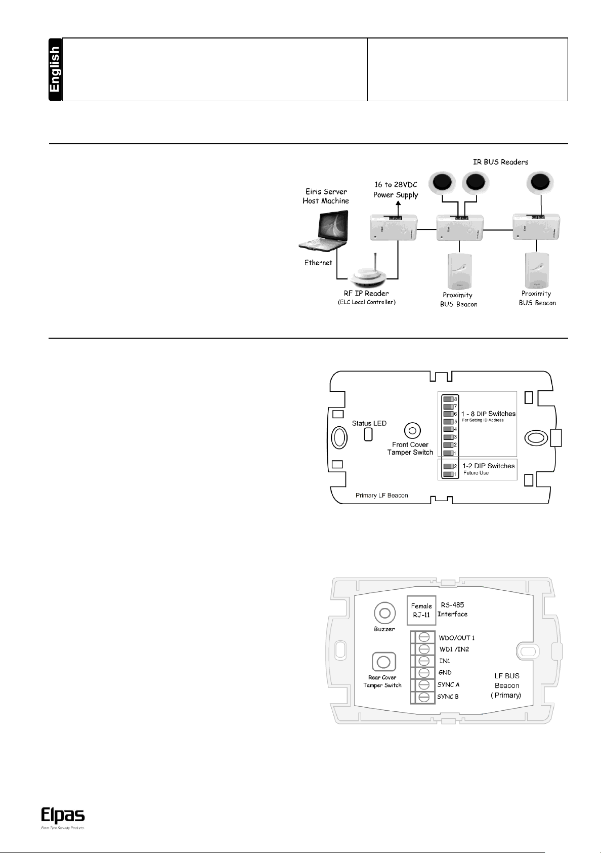
LF BUS Beacon (Primary) - Sample Network Topology
Introduction
This installation guide provides basic instructions for common LF BUS Beacon installation scenarios
CAUTION! It is important that you read, understand, and follow the instructions in this document. If you have questions, call your local Elpas support representative.
Primary/Secondary Beacons – Front View
Front Cover Tamper Switch: All BUS beacons contain a
tamper switch which indicates non-authorized attempts to
remove the device’s front cover when in operation.
The tamper switch is also used to control the coverage area of
the LF field. (See page 4 for details.)
Status LED: All BUS beacons contain a Red, Green and
Orange LED array that detail the status of the devices:
Green LED
o Unregistered: Flashes once/second
o Power up/Communication Loss/Sync Cable Disconnected:
Flashes once/second
Red LED
o Invalid ID: Flashes once/second - See page 4 for additional details
o Device Tamper: Flashes once/second
o Output Activated: Flashes once
Orange LED
o Flashes to indicate the selected LF field range - See page 5 for
additional details
DIP Switch: Only the Primary Beacon has an eight-position DIP
Switch for assigning its ID Address. (See page 4 for details.)
Primary/Secondary Beacons – Rear View
Rear Cover Tamper Switch: All BUS Beacons contain a dual
purpose tamper switch which indicates non-authorized attempts
to remove the device’s rear cover when in operation.
RS-485 Interface: All BUS beacons contain a female RJ-11
connector for linking to the RS-485 Junction Box. This connector
is used for both power & data. (See page 2 for details)
Buzzer: The beacon has a buzzer that sounds when an
improper ID Address has been assigned. (See page 4 for
details.)
General Purpose Inputs: All BUS Beacons have general
purpose inputs. (See page 6 for details.)
Digital Output: The primary beacon and the secondary beacon
have one digital output. (See page 6 for details.)
LF BUS Beacon (Front View-Cover Removed)
LF BUS Beacon (Rear View)
IMPORTANT: BUS Beacons MUST BE powered-down while wiring the
unit’s I/Os and when connecting to the RS-485 BUS. This will prevent
accidental shorts/spikes to cause damage to the devices
Page 2
LF BUS Beacon – Installation Guide
www.elpas.com
Page 2 of 7
V22/Jan 2013
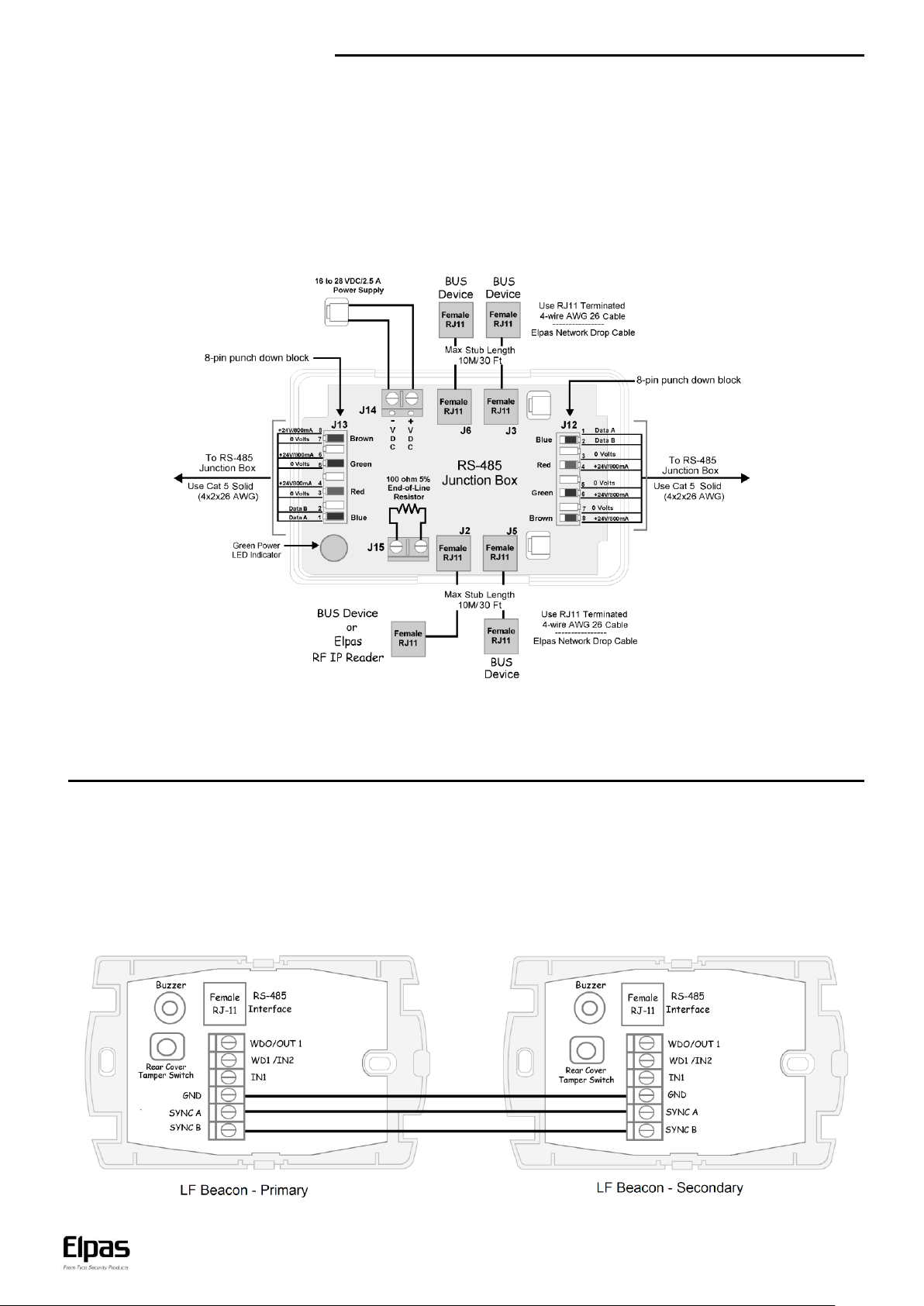
Recommended RS-485 Backbone Cable Type: CAT5 Solid (4x2x26AWG)
For Power: Use three-twisted pairs (six conductors) between RS-485 Junction Boxes
For Data: Use one-twisted pair (two conductors) between RS-485 Junction Boxes
RS-485 BUS/Stub Topology
The RS-485 BUS MUST BE wired using a BUS/Stub topology where the BUS Master (a RF IP Reader or an ELC Controller) is connected
anywhere along the BUS. The topology supports data transmission between the BUS Master and up to 15 Elpas BUS Devices (such as RF or IR
Readers; LF Beacons primary & secondary), Elpas Display Panels and 6x6 I/O Modules using Elpas RS-485 Junction Boxes (P/N: 5-JBA00485).
IMPORTANT NOTE: Only 1 RF IP Reader/ELC Controller and up to 7 RF BUS Readers may coexist together on a single BUS.
200M/650Ft: Max. BUS length 10M/30Ft: Max. Stub length 100 Ohm Termination: Required each end of the BUS.
Primary/Secondary Synchronization
Up to four LF BUS Beacons can be deployed in ‘Primary–Secondary’ Daisy-Chain or Star Topologies in order to cover large double-doors or
architectural complex indoor entrance/exit areas.
When deploying either of these two topologies, the LF fields generated by the secondary beacons MUST BE synchronized to pulse at precisely
the same moment in time as the LF field generated by the primary unit in order to avoid mutual interference between any of the LF fields.
To implement Primary/Secondary Synchronization a Sync Data Link (typically using a 2x2x26 Category 5 cable) needs to be physically
connected between the Primary Beacon and all of the Secondary devices.
Page 3
LF BUS Beacon – Installation Guide
www.elpas.com
Page 3 of 7
V22/Jan 2013
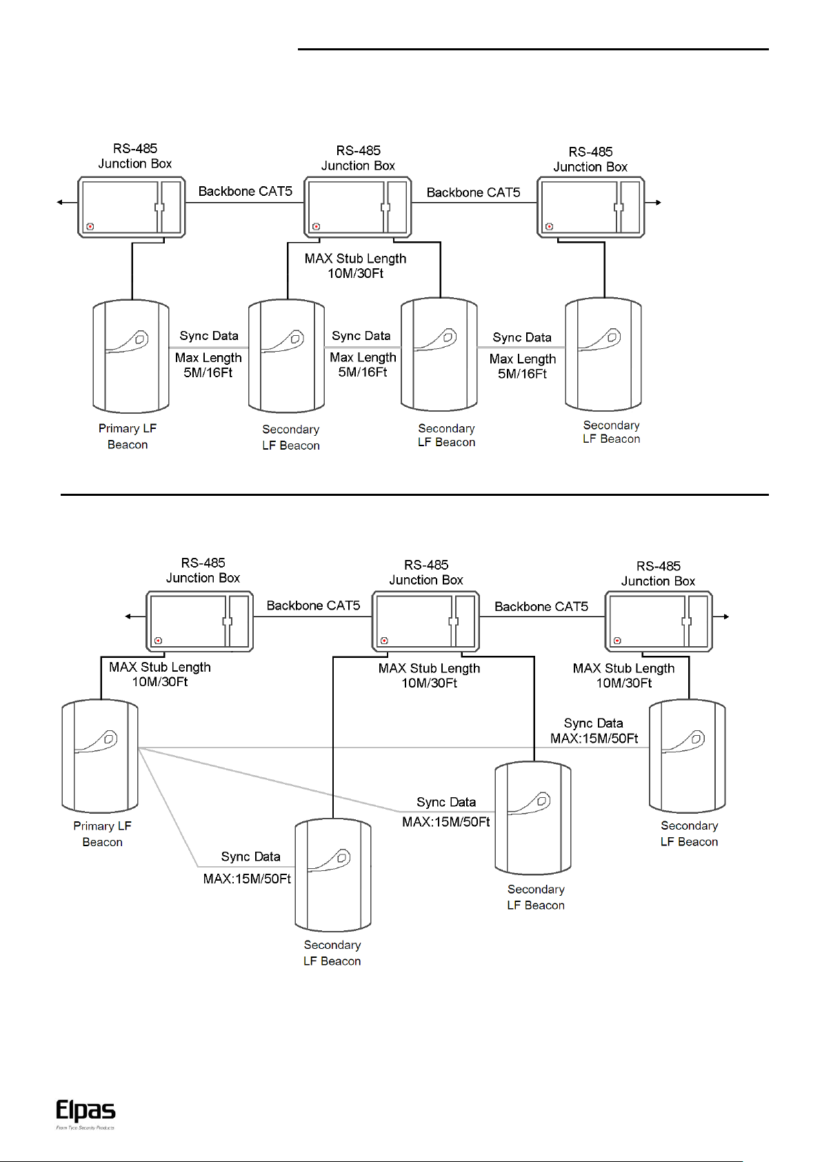
Primary/Secondary Synch Data Connection Diagram – Daisy-Chain Topology
Primary/Secondary Synch Data Connection Diagram – Star Topology
Page 4

LF BUS Beacon – Installation Guide
www.elpas.com
Page 4 of 7
V22/Jan 2013
The ID address is assigned using a binary coded hexadecimal number.
Switches 1-4 (high nibble) are used to set the first hexadecimal digit while
switches 5-8 (low nibble) are used to set the second hexadecimal digit.
Together, the two hexadecimal digits provide a total of 256 possible
Neuron ID addresses.
ID Address Setup
Before initial power-up, the Primary LF BUS Beacon must be assigned a unique ID Address (Neuron ID) in order for the Eiris Software
Platform or an Elpas Local Controller to be able to identify the device. Convert the Neuron ID (typically using a scientific calculator) into the twodigit hexadecimal number that correctly corresponds to the DIP switch found on the LF Beacon. This hexadecimal number will be used to
register the beacon’s ID address into the EIRIS or the ELC database.
NOTE: It is vital that a newly assigned ID Address does not conflict with any other ID Address that has already been assigned to any other beacon.
The following Neuron ID Addresses SHOULD NOT BE ASSIGNED to the Primary LF BUS Beacon: 0x00 (00000000), 0x13 (),
0x35 (), 0x4B (), 0x4D (), 0x5C (), 0xB8 (), 0xD5 (), 0xDC (), 0xFF (11111111),
0xFE (11111110) and 0x7F (01111111).
Should any of the above ID addresses be assigned by mistake, the beacon will not properly function. Additionally the beacon’s Red Status LED will
continually flash; and the device’s buzzer will repetitively sound.
Use the beacon’s 8-poisition DIP Switch to set the ID address (in binary format) of the beacon as illustrated below
The figure below shows how to set the hex digitals ‘0’ to ‘F’
Below are three examples of addresses set in hexadecimal:
Page 5

LF BUS Beacon – Installation Guide
www.elpas.com
Page 5 of 7
V22/Jan 2013
For Primary Beacons: Primary Beacons support four ranges from10cm/4.0 inches to 1.5m/5ft in radius.
To cycle to the next range press the tamper switch twice.
Each time you cycle to the next LF field range, the Orange LED will flash the applicable number of times
to indicate the selected range:
One flash - Shortest range
Two flashes - Medium 1 range
Three flashes - Medium 2 range
Four flashes - Maximum range
Single Door Placement
Mount the primary beacon on the wall adjacent to the opening
side of the door, at a height of 1.2m/4Ft. above the floor.
Beacons MUST NOT BE MOUNTED on any metallic surfaces
and should be positioned at least 30cm/12in from any metal
barriers (such as signs/pillars/beams) in any direction
Additionally all beacons MUST BE MOUNTED as far away as
possible from all other pieces of equipment that may emit
magnetic fields (such as large electrical motors, HVAC and
refrigeration compressors.
LF Field Adjustment
The size of the LF field generated by any of the BUS Beacons can be adjusted using the device’s Front Cover Tamper Switch to control the
actual coverage of the LF field and to reduce the unwanted signal penetration
For Secondary Beacons: Secondary Beacons support only the Medium 2 and Maximum Ranges. To cycle between the two ranges press the
tamper switch twice. There will be no LED indication of the selected field range.
NOTE: In practice the coverage area (for each range mode) regardless of beacon type may vary +/- 20% by specific Active RFID Tag as well as
the active RFID Tag’s physical orientation in relation to the LF field.
Double Door Placement
A primary/secondary configuration may be installed by mounting the primary beacon to the right of the double door entrance area and
up to three secondary device(s) to the left of the doors, at a height of 1.2m/4Ft above the floor Ensure that all of the beacons are no
more than 1m/3ft from the doors. The resulting LF fields are automatically synchronized in real time to avoid problems associated with
coverage area overlap.
Page 6

LF BUS Beacon – Installation Guide
www.elpas.com
Page 6 of 7
V22/Jan 2013
General Purpose Inputs
Both the primary beacon (P/N: 5-ALA00125-12) and the
secondary beacon (P/H: 5-ALA00125-2) have two general
purpose inputs designated IN1 and IN2.
EOL supervision may be added to either of these inputs to detect:
Open, Close, Line Cut and Line Short circuit conditions using
optional Elpas End-of-Line Terminators (P/N: 5-IOX00001).
Digital Output
Both the primary beacon (P/N: 5-ALA00125-12) and the
secondary beacon (P/H: 5-ALA00125-2) have one general
purpose digital output, which provides open-collector switching
(up to 100mA, 28Vdc)
Note: Primary beacons that contain the Wiegand output option
(P/N: 5-ALA00125-11) contains only Input1.
Transmission Suppression Option
Input1 on all BUS Beacons may be used to disable the LF field by
shorting IN1 with GND. This allows the user to temporary override
the beacon with a security detector, such as a passive infrared.
However Input1 may be used as a normal general purpose input
when an Elpas End-of-Line Terminator, (P/N: 5-IOX00001) is
connected to the input as illustrated in the above section.
Recommended Cable: 22 AWG, unshielded/twisted pair
Wiegand Output
Primary beacons with the Wiegand output (P/N: 5-ALA00125-11)
provide one 26-bit Wiegand output (instead of a digital output) for
sending Elpas tag IDs to third-party access control panels.
Recommended Cable: 22 AWG, unshielded/twisted pair
Page 7

LF BUS Beacon – Installation Guide
Page 7 of 7
V22/Jan 2013
W.E.E.E. Product Recycling Declaration
For information regarding the recycling of this product you must contact the company from which you orignially purchased it.
If you are discarding this product and not returning it for repair then you must ensure that it is returned as identified by your supplier.
This product is not to be thrown away with everyday waste - Directive 2002/96/EC Waste Electrical and Electronic Equipment.
Standards Compliance
This device complies with Part 15 of the FCC Rules and RSS-210 of
Industry and Science Canada. Operation is subject to the following two
conditions: (1) This device may not cause harmful interference, and (2)
this device must accept any interference received, including
interference that may cause undesired operation
This device complies with Industry Canada license-exempt RSS
standard(s). Operation is subject to the following two conditions: (1)
this device may not cause interference, and (2) this device must accept
any interference, including interference that may cause undesired
operation of the device
Product Warranty
Elpas Ltd. (the Company), and its affiliates, warrants its products
(hereinafter referred to as "the Product”) to be free of defects in
materials and workmanship under normal operating conditions and use
for a period of one year from the date of shipment by Elpas. The
Company’s obligations shall be limited within the warranty period, at its
option, to repair or to replace the defective Product or any defective
component or part thereof. To exercise this warranty, the product must
be returned to the manufacturer freight prepaid and insured
This warranty does not apply to repairs or replacement caused by
improper installation, Product misuse, failure to follow installation or
operating instructions, alteration, abuse, accident, tampering, repair by
anyone other than Elpas, external causes, and failure to perform
required preventive maintenance. This warranty also does not apply to
any products, accessories, or attachments used in conjunction with the
Product, including batteries, which shall be covered solely by their own
warranties, if any. Elpas shall not be liable for any damage or loss
whatsoever, whether directly, indirectly, incidentally, consequentially or
otherwise, resulting from a malfunction of the Product due to products,
accessories, or attachments of others, including batteries, used in
conjunction with the Product
Elpas MAKES NO EXPRESS WARRANTIES EXCEPT THOSE
STATED IN THIS STATEMENT. ELPAS DISCLAIMS ALL OTHER
WARRANTIES, EXPRESS OR IMPLIED, INCLUDING WITHOUT
LIMITATION IMPLIED WARRANTIES OF MERCHANTABILITY AND
FITNESS FOR A PARTICULAR PURPOSE. ELPAS’S SOLE
RESPONSIBILITY FOR WARRANTY CLAIMS IS LIMITED TO
REPAIR OR TO REPLACE AS SET FORTH IN THIS STATEMENT
Elpas shall have no liability for any death, personal injury, property
damage, or other loss whether direct, indirect, incidental,
consequential, or otherwise, based on a claim that the Product failed to
function. However, if Elpas is held liable, whether directly or indirectly,
for any loss or damage arising under this limited warranty or otherwise,
regardless of cause or origin, the company's maximum liability shall be
limited to the purchase price of the Product, which shall be fixed as
liquidated damages and not as a penalty, and shall be the complete
and exclusive liability of Elpas
Elpas shall not, under any circumstances whatsoever, be liable for any
inaccuracy, error of judgment, default, or negligence of Elpas, its
employees, officers, agents, or any other party, or of the purchaser or
user, arising from any assistance or communication of any kind
regarding the configuration, design, installation, or creation of security
system involving the Product, that being the responsibility of the
purchaser or user
If Elpas is unable to make such repair or replacement, the company’s
entire liability shall be limited to the cost of a reasonable substitute
product. Elpas shall not be responsible for any dismantling, installation,
reinstallation, purchasing, shipping, insurance, or any similar charges
Le présent appareil est conforme aux CNR d'Industrie Canada
applicables aux appareils radio exempts de licence. L'exploitation est
autorisée aux deux conditions suivantes : (1) l'appareil ne doit pas
produire de brouillage, et (2) l'utilisateur de l'appareil doit accepter tout
brouillage radioélectrique subi, même si le brouillage est susceptible
d'en compromettre le fonctionnement
Warning!
Elpas is not responsible for any radio or TV interference caused by
unauthorized modifications to this equipment. Such modifications could
void the user’s authority to operate the equipment.
Elpas shall have no liability for any damages, including without
limitation, any direct, indirect, incidental, special, or consequential
damages, expenses, costs, profits, lost savings or earnings, or other
damages arising out of the use of the Product or the removal,
installation, reinstallation, repair or replacement of the Product or any
related events. In the event that there is any liability against Elpas,
such liability shall be limited to the purchase price of the Product which
amount shall be fixed as liquidated damages
The purchaser and user understand that this Product may be
compromised or circumvented by intentional acts; that the Product will
not in all cases prevent death, personal injury, property damage, or
other loss resulting from burglary, robbery, fire or other causes; and
that the Product will not in all cases provide adequate warning or
protection. The purchaser and user also understand that a properly
installed and maintained alarm may reduce the risk of events such as
burglary, robbery, and fire without warning, but it is not insurance or a
guarantee that such events will not occur or that there will be no death,
personal injury, property damage, or other loss as a result of such
events
By purchasing the Product, the purchaser and user shall defend,
indemnify and hold Elpas, its officers, directors, affiliates, subsidiaries,
agents, servants, employees, and authorized representatives harmless
from and against any and all claims, suits, costs, damages, and
judgments incurred, claimed, or sustained whether for death, personal
injury, property damage, or otherwise, because of or in any way related
to the configuration, design, installation, or creation of a security
system involving the Product, and the use, sale, distribution, and
installation of the Product, including payment of any and all attorney’s
fees, costs, and expenses incurred as a result of any such events
The purchaser or user should follow the Product installation and
operation instructions and test the Product and the entire system at
least once each week. For various reasons, including but not limited to
changes in environmental conditions, electric, electronic, or
electromagnetic disruptions, and tampering, the Product may not
perform as expected. The purchaser and user are advised to take all
necessary precautions for the protection and safety of persons and
property
This statement provides certain legal rights. Other rights may vary
by state or country. Under certain circumstances, some states or
countries may not allow exclusion or limitation of incidental or
consequential damages or implied warranties, so the above exclusions
may not apply under those circumstances and in those states or
countries
Elpas reserves the right to modify this statement at any time, in its sole
discretion without notice to any purchaser or user. However, this
statement shall not be modified or varied except by Elpas in writing,
and
Elpas does not authorize any single individual to act on its behalf to
modify or vary this statement
Any questions about this statement should be directed to Elpas.
 Loading...