

Page 1
www.elotouch.com
© 2014 Elo Touch Solutions, Inc. All rights reserved.
Elo Touch Solutions Technical Support
Online self-help: www.elotouch.com/go/websupport
Technical Support contacts in your region:
www.elotouch.com/go/contactsupport
The information in this document is subject to change without notice. Elo Touch Solutions, Inc. and its Afliates (collectively “Elo”) makes
no representations or warranties with respect to the contents herein, and specically disclaims any implied warranties of merchantability or
tness for a particular purpose. Elo reserves the right to revise this publication and to make changes from time to time in the content hereof
without obligation of Elo to notify any person of such revisions or changes.
No part of this publication may be reproduced, transmitted, transcribed, stored in a retrieval system, or translated into any language or
computer language, in any form or by any means, including, but not limited to, electronic, magnetic, optical, chemical, manual, or otherwise
without prior written permission of Elo Touch Solutions, Inc.
Elo (logo) and Elo Touch Solutions are trademarks of Elo and its Afliates.
North America
Elo Touch Solutions
1033 McCarthy Boulevard
Milpitas, CA 95035
800-ELO-TOUCH
Tel +1 408 597 8000
Fax +1 408 597 8050
customerservice@elotouch.com
Europe
Tel +32 (0)16 70 45 00
Fax +32 (0)16 70 45 49
elosales@elotouch.com
Asia-Pacic
Tel +86 (21) 3329 1385
Fax +86 (21) 3329 1400
www.elotouch.com.cn
Latin America
Tel 786-923-0251
Fax 305-931-0124
www.elotouch.com
Revision A
P/N E001016
Quick Installation Guide
X-Series
All-in-One TouchComputer
Included items:
1x X-Series Touchcomputer
1x US Power Cable
1x European Power Cable
1x Power Brick
Page 2
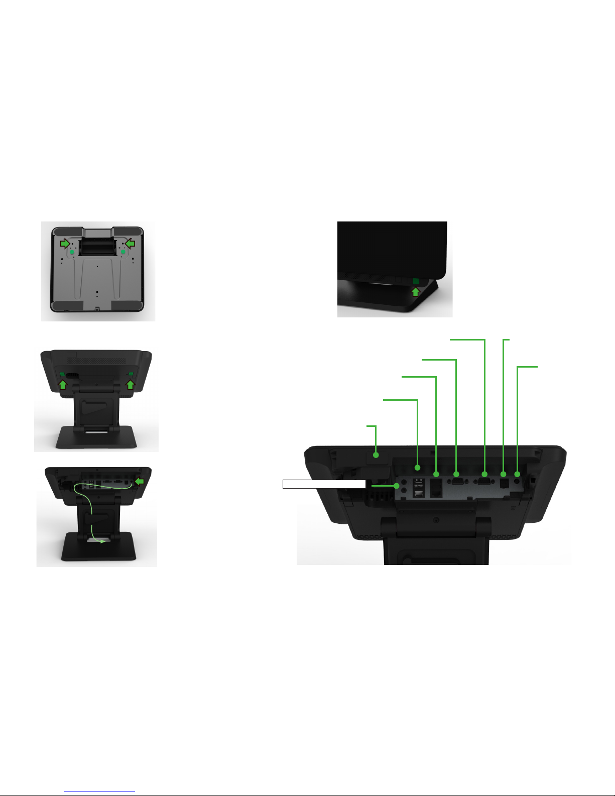
The stand supports both
upright and lowered
orientations. The stand is
set to the lowered postion
from the factory. Change
the orientation to upright by
removing the green colored
screws from the bottom of
the stand and install them in
the location marked by the
arrows
Go to www.elotouch.com/support to download user manual.
Tilt the display back to
access the I/O connections
and remove the cable cover.
Connect the power cable to
the DC power jack marked
by the arrow. Then route the
cable through the cable clips
and through the bottom of the
stand.
The power button is located at
the bottom as shown.
RS-232 and
USB X2
USB X2
Ethernet and
USB X2
+24V PUSB
(X3/X5/X7 models only)
DC Power
Input
VGA
Serial RS-0232
Mic / headphone out
 Loading...