

Page 1
USER MANUAL
Elo Touch Solutions
15" X-Series RevB All-in-one Touch computer
17" X-Series RevB All-in-one Touch computer
20" X-Series RevB All-in-one Touch computer
Page 2

User Manual: X-Series
UM600139 Rev A, page 1 of 48
Copyright © 2018 Elo Touch Solutions, Inc. All Rights Reserved.
No part of this publication may be reproduced, transmitted, transcribed, stored in a retrieval system, or translated into any language or computer language, in
any form or by any means, including, but not limited to, electronic, magnetic, optical, chemical, manual, or otherwise without prior written permission of Elo Touch
Solutions, Inc.
Disclaimer
The information in this document is subject to change without notice. Elo Touch Solutions, Inc. and its Affiliates (collectively “Elo”) makes no representations or
warranties with respect to the contents herein, and specifically disclaims any implied warranties of merchantability or fitness for a particular purpose. Elo reserves
the right to revise this publication and to make changes from time to time in the content hereof without obligation of Elo to notify any person of such revisions or
changes.
Trademark Acknowledgments
Elo, Elo (logo), Elo Touch, Elo Touch Solutions, AccuTouch, TouchPro, Elo TouchSystems, IntelliTouch, IntelliTouch, and TouchTools are trademarks of Elo and its
Affiliates. Windows is a trademark of Microsoft Corporation.
Page 3

User Manual: X-Series
UM600139 Rev A, page 2 of 48
Table of Contents
Section 1: Introduction ......................................................................................................................................................................................................................... 3
Section 2: Installation ......................................................................................................................................................................................................................... 15
Section 3: Operation .......................................................................................................................................................................................................................... 19
Section 4: Options and Upgrades ...................................................................................................................................................................................................... 32
Section 5: Technical Support ............................................................................................................................................................................................................. 34
Section 6: Safety & Maintenance ....................................................................................................................................................................................................... 36
Section 7: Regulatory Information ...................................................................................................................................................................................................... 39
Section 8: Warranty Information .......................................................................................................................................................................................................... 0
Page 4

User Manual: X-Series
UM600139 Rev A, page 3 of 48
Section 1: Introduction
Product Description
The X-Series provides a powerful, compact and configurable touch computer in three screen sizes: 15”, 17” and 20”. These models are ruggedized
and available with a choice of industry-leading Elo touch technologies: AccuTouch 5 wire resistive, IntelliTouch
surface acoustic wave and
TouchProTM projected capacitive (PCAP). The X-Series incorporates 24-bit color at resolutions of 1024x768 (15”), 1280x1024 (17”) and 1920x1080
(20”). The liquid crystal display (LCD) provides excellent performance when displaying graphics and images. The X2 models are built with the
latest Intel Celeron Apollo Lake processors providing outstanding performance with low heat and energy dissipation making them well suited for
environments where noise is an issue or where dirt and dust might impact fan performance. The X3, X5, and X7 models are built with the 6th
generation Intel Core-i3, i5 and i7 Sky Lake fan cooled processors with HD5400 graphics. These processors provide premium performance
when needed. The X5 and X7 models also support Intel’s VPro technology.
The X-Series touch computers offer a stylish design with optional customer installable peripherals and are designed with service in mind. These
models support multiple memory and storage configurations.
Precautions
Follow all warnings, precautions and maintenance tips as recommended in this user manual to maximize the life of your unit and prevent risks to
user safety. See Chapter 6 for more information on safety.
This manual contains information that is important for the proper setup and maintenance of the X-Series All-in-one touch computers. Before
setting up and powering on your X-Series unit, please read through this manual in detail seriously and carefully .
Page 5
User Manual: X-Series
UM600139 Rev A, page 4 of 48
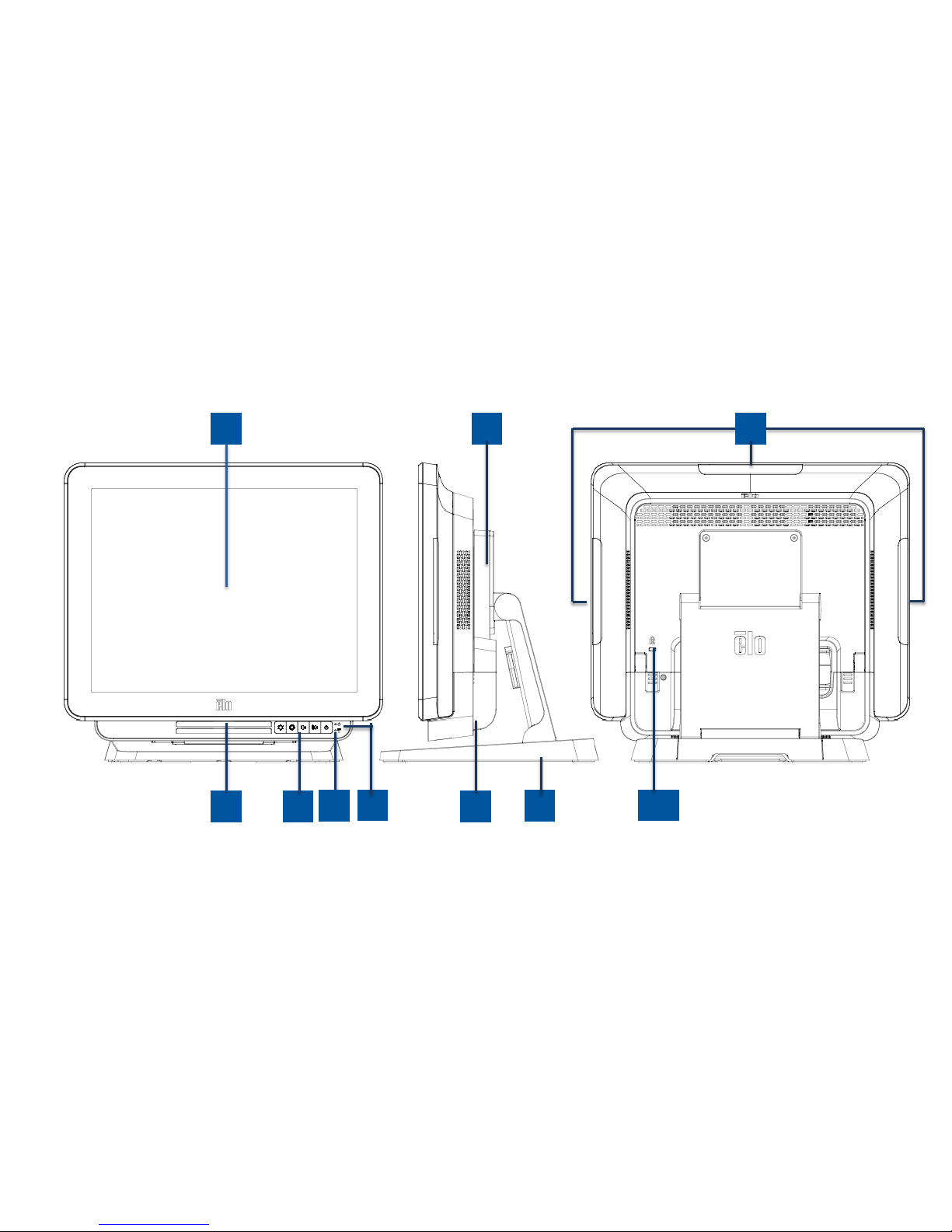
X-Series Layout
X-Series 15” and 17” Models
Figure 1. X-Series 15” and 17” front view, right side view, and back view
3
2
1
5
6
7
8
9
4
10
Page 6
User Manual: X-Series
UM600139 Rev A, page 5 of 48
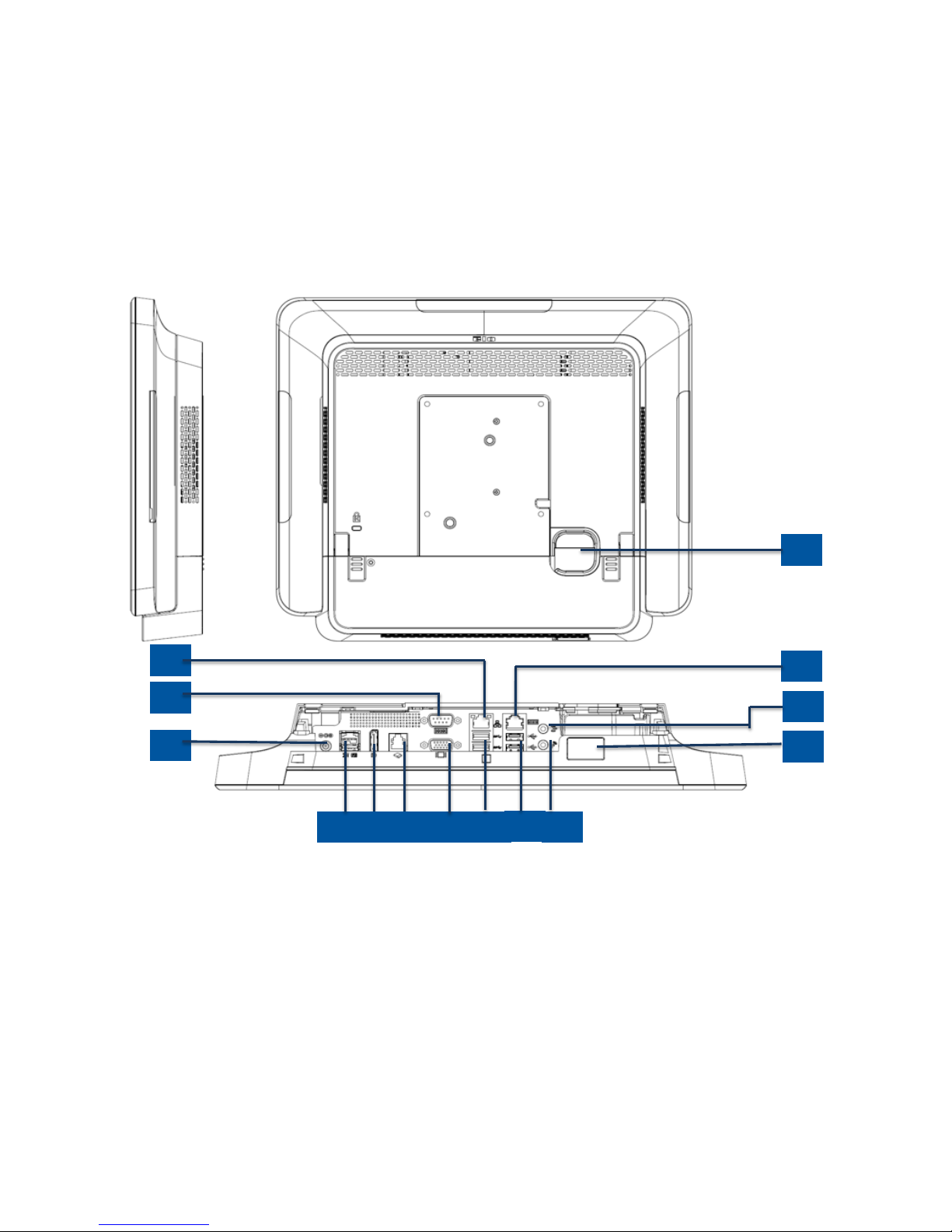
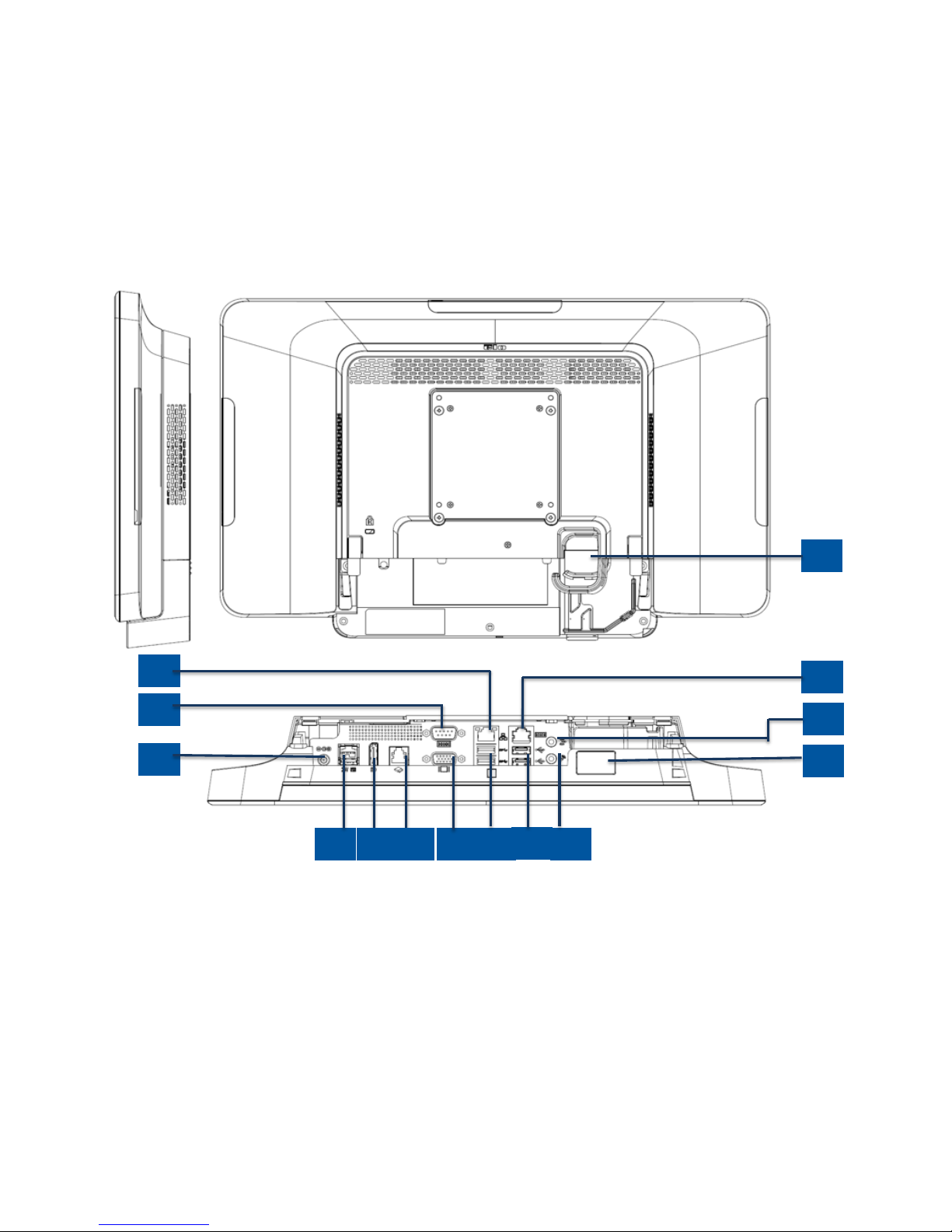
Figure 2. X-Series 15” and 17” back view and rear IO view
12
22
11
14
15
16
17
18
20
21
19
13
23
24
Page 7
User Manual: X-Series
UM600139 Rev A, page 6 of 48
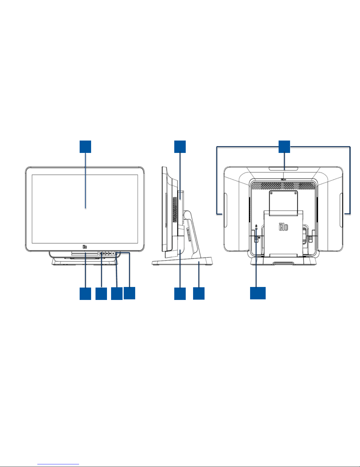
X-Series 20” Model
Figure 3. X-Series 20” front view, right side view, and back view
3
2
1
5
6
7
8
9
4
10
Page 8
User Manual: X-Series
UM600139 Rev A, page 7 of 48
Figure 4. X-Series 20” back view and rear I/O view
12
2
11
14
15
16
17
18
20
21
19
13
23
24
Page 9
User Manual: X-Series
UM600139 Rev A, page 8 of 48
1
Display with touch
13
Serial Port (COM1/RS-232)
2
Speaker
14
VGA Output (D-Sub)
3
Front On Screen Display Control
Buttons
15
USB 3.0 Port
4
Wireless indicator LED
16
USB 2.0 Port (X2/X3)
USB 3.0 Port (X5/X7)
5
Power indicator LED
17
Ethernet LAN Port
6
Stand Module
18
Serial Port (COM2/RJ-45)
7
Cable Cover
19
Audio Port (Line-out)
8
Expansion Module (Optional)
20
Front USB Port
9
Edge USB ports for Elo Peripherals
21
Microphone (built-in)
10
Kensington Lock
22
Cable Exit Hole
11
Power Connector (DC-IN)
23
Display Port
12
+24 Volt Powered USB Port
24
Cash Drawer Port (A/B)
1. Display with Touch
The 15” and 17” models are available with the following touch technologies.
- AccuTouch, zero-bezel 5 wire resistive
- IntelliTouch, zero-bezel multi-touch surface acoustic wave
- IntelliTouch, single touch surface acoustic wave
- TouchPro, zero-bezel TouchPro projective capacitive (PCAP)
The 20” model is only available with TouchPro, projective capacitive (PCAP) touch.
2. Speaker
Two, integrated, 1 watt speakers provide audio output for video and music playback.
3. Front On Screen Display Control Buttons
The front On Screen Display (OSD) control buttons provide the ability to manage volume and brightness. See section 3 for
details.
Page 10

User Manual: X-Series
UM600139 Rev A, page 9 of 48
4. Wireless indicator LED
The wireless indicator LED flashes blue when the X-Series is connected to a Wi-Fi network and when the X-Series Bluetooth
functionality is active.
5. Power indicator LED
The power indicator LED shows the state of the touch computer. See section 3 for more details.
6. Stand Module
The stand module is a robust design supporting all 15”, 17” and 20” Elo All-in-one touch computers.
7. Cable cover
Access to the IO ports are made via the rear cable cover.
8. Expansion Module (Optional)
The expansion module kit provides additional connectivity capability on the X-Series. Please reference the Expansion Module
section for function description in detail below.
9. Edge USB Port (Accessory KITs - connection)
The X-Series includes edge USB ports on the display head for mounting optional peripherals. The peripherals can be mounted
and fixed at the edge to meet many IO peripheral requirements.
10. Kensington Lock
Kensington Lock is a standard anti-theft mechanism on the X-Series to secure the desktop to the desired mounting location.
The Kensington cable lock is not included.
11. Power Connector (DC-IN)
To power up the X-Series, plug the DC connector of the AC/DC power adapter kit into the power connection on the device.
Page 11

User Manual: X-Series
UM600139 Rev A, page 10 of 48
12. +24 Volt Powered USB Port
The +24 Volt Powered USB Port spec is design for all X-Series models. The maximum power rating of the +24 Volt Power USB is 24
Volt at 2.3 Amps. Please ensure your power USB device does not exceed the following:
- 24 Volts at 2.3 Amps for a continuous load
- Peak load or inrush current of 5 Amps for 100ms and 8 Amps for 2ms
13. Serial Port (COM1/RS-232)
The serial port is a standard native RS-232 interface connection.
14. VGA Output (D-Sub)
The X-Series system has a VGA output (D-Sub) to support a second display monitor.
15. USB 3.0 Port
Two standard Super Speed USB 3.0 ports are available on the rear input/output panel of the X-Series system.
16. USB Port Configuration
- Two USB 2.0 Ports for X2 / X3 system configuration only.
- Two USB 3.0 Ports for X5 / X7 system configuration only.
17. Ethernet LAN Port
The Ethernet LAN Port provides up to 1Gbps speed capability for networking the X-Series.
18. Serial Port (COM2/RJ-45)
The serial port is a native RS-232 specification for RJ-45 interface connection.
19. Audio port (Line-out)
The audio port is designed for X-Series headphone connectivity (Line-out).
Page 12
User Manual: X-Series
UM600139 Rev A, page 11 of 48
20. Front USB Port
The two front USB Ports are standard USB 2.0 connectors providing user easy access the USB connections.
21. Microphone (built-in)
A built-in microphone port is available, allowing easy connection to the X-Series system.
22. Cable Exit Hole
The cable exit hole is design for cable routing when the cables connect to rear port for each function. It provides an
enhanced cable management experience for X-Series setup.
23. Display Port
The X-Series system has a Display Port output to support a second display monitor.
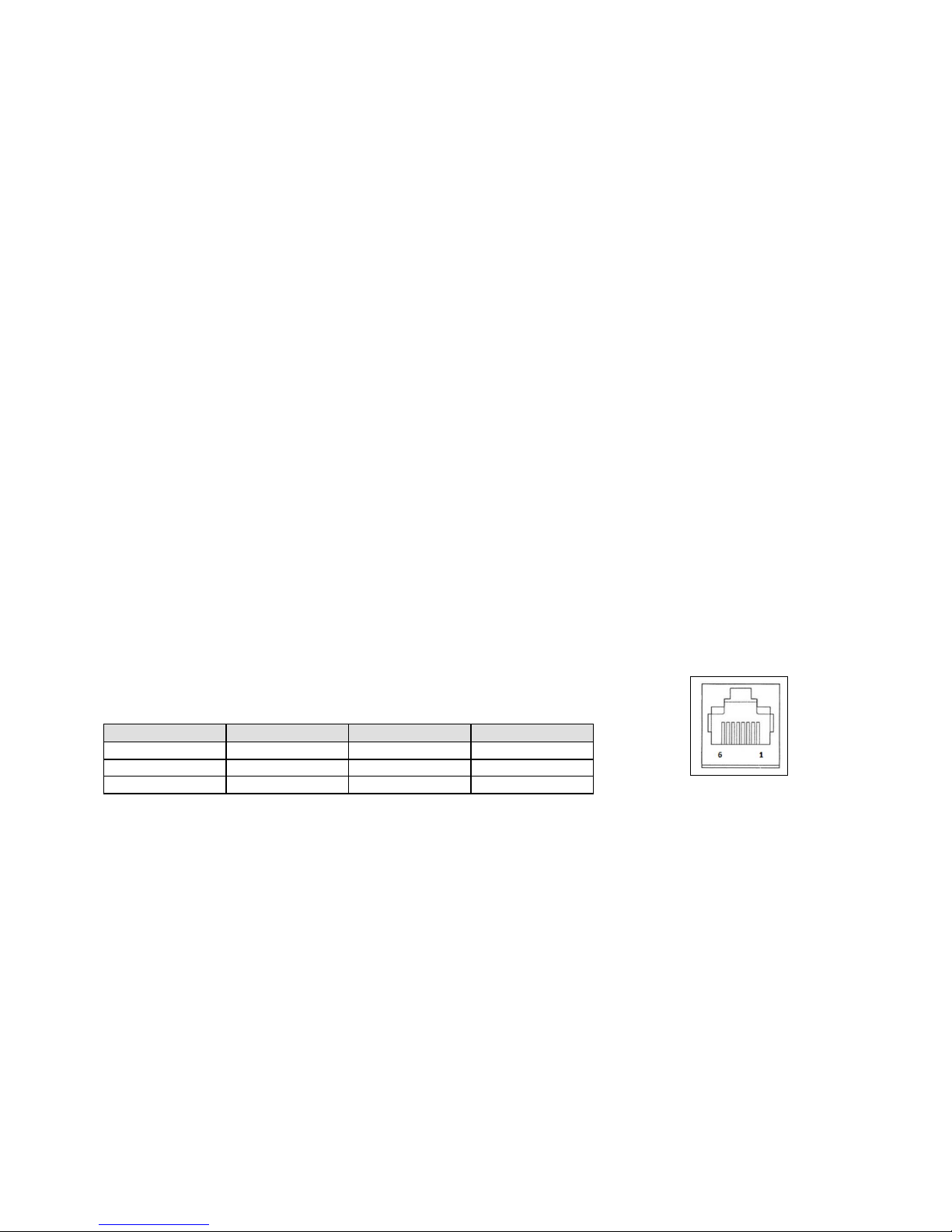
24. Cash Drawer Port (A/B)
The main cash drawer port is a RJ-12 interface design and provides switchable operation at +12VOLTs and +24VOLTs. The
default setting is at +24 Volts and the settings are user programmable in the system BIOS menu.
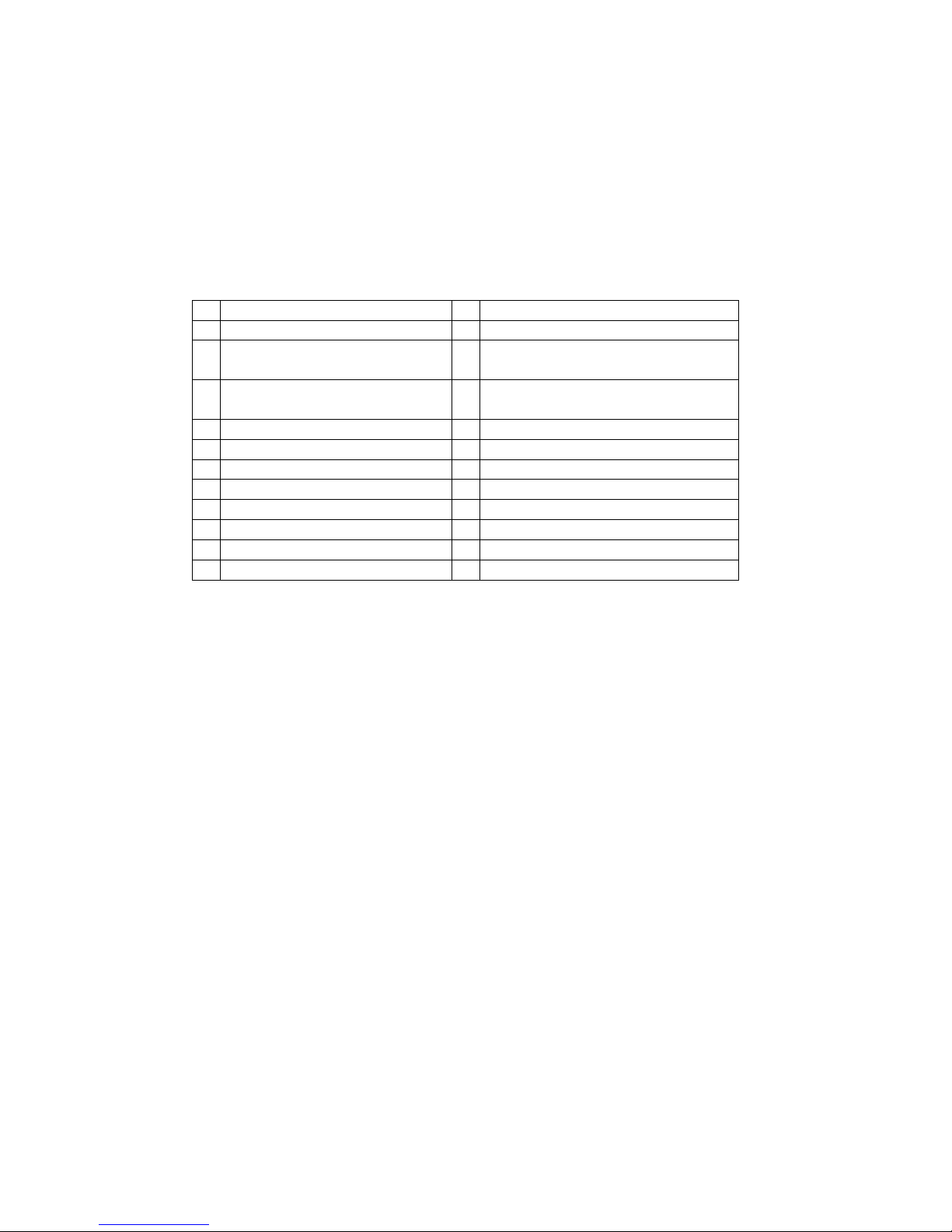
a. Cash Drawer Port Pin assignment
Pin #
Signal Name
Pin #
Signal Name
1
DETECT B
2
Channel A
3
DETECT A
4
POWER
5
Channel B
6
GND
Page 13
User Manual: X-Series
UM600139 Rev A, page 12 of 48
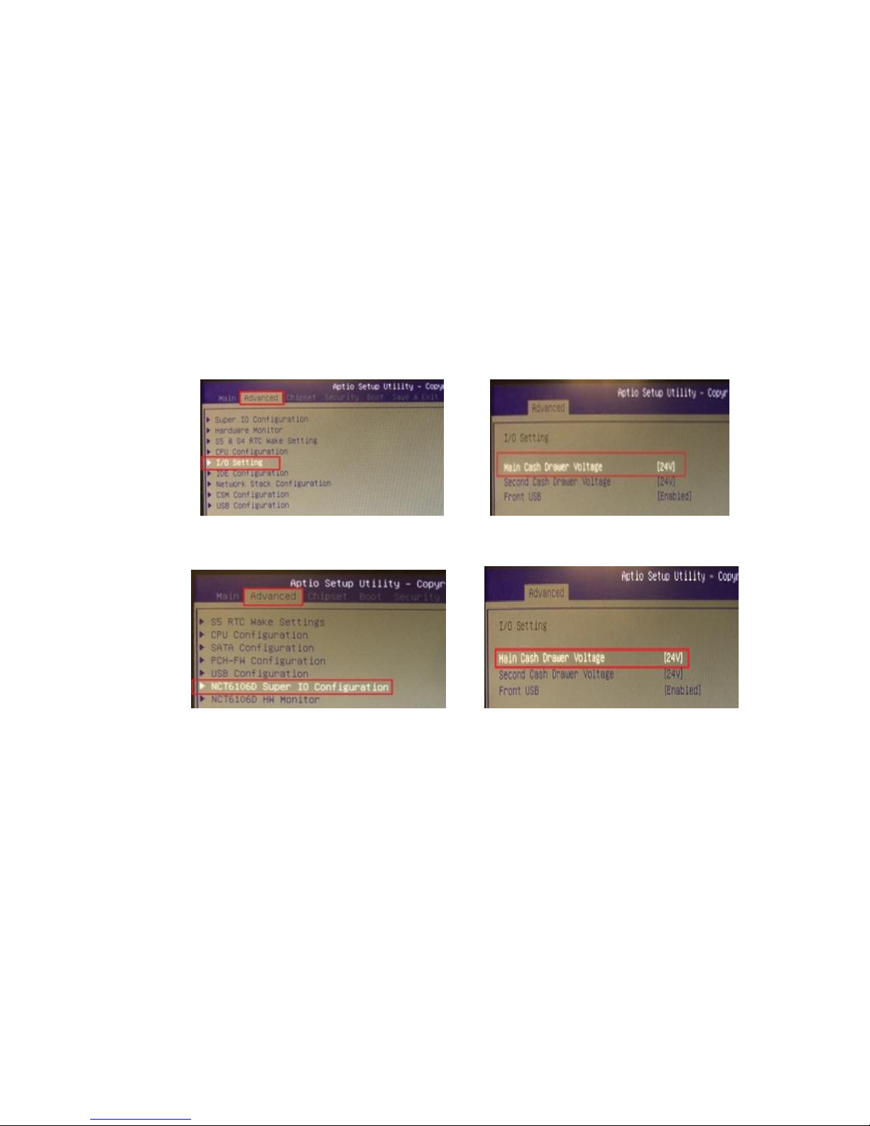
b. Cash Drawer +12VOLT/+24VOLT selection
First enter the BIOS by pressing [Delete] while restarting. For X2 series configurations: Enter BIOS Setting
menuAdvancedI/O Setting Main Cash Drawer voltage 24 Volt or 12 Volt
For X3/X5/X7 series configurations: Enter BIOS Setting menuAdvancedNTC6106D Super IO Configuration Main Cash
Drawer Voltage 24 Volt or 12 Volt
Page 14
User Manual: X-Series
UM600139 Rev A, page 13 of 48
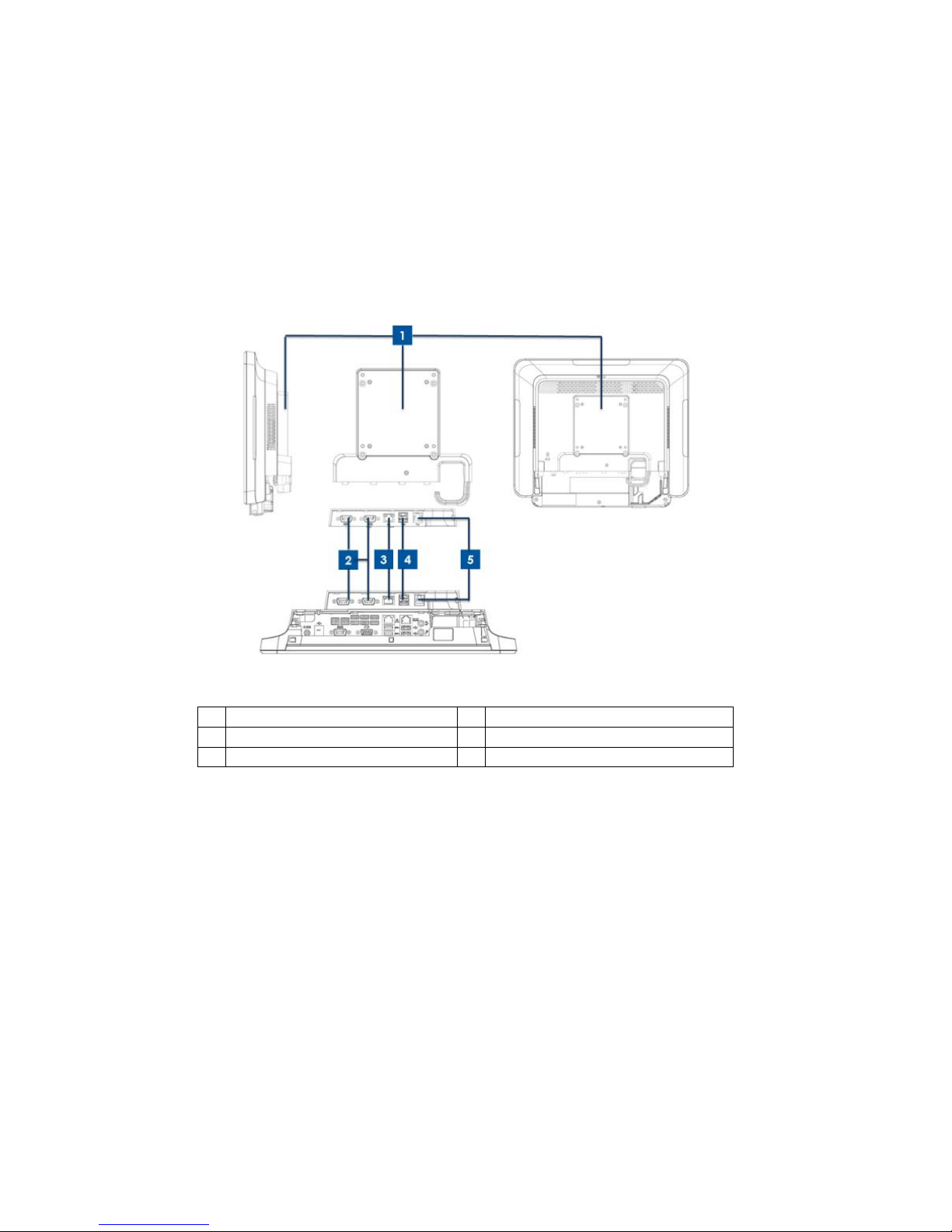
X-Series Expansion Module (optional peripheral) Layout
Figure 5. X-Series expansion module clerk right side view, module IO port view, and back view.
1
Expansion Module
4
+12 Volt Powered USB Port (Green)
2
Serial Port (COM3/COM4)
5
Cash Drawer Port
3
Ethernet LAN Port
1. Expansion Module
The expansion module option kit provides additional connectivity capability. It is mounted to the center of the system back
cover as a peripheral port for all X-Series systems.
2. Serial Port (COM3/COM4,RS-232)
The serial port is a standard native RS-232 interface connection. The COM3 is close to LAN port, and the COM4 is next to COM3
port.
Page 15

User Manual: X-Series
UM600139 Rev A, page 14 of 48
3. Ethernet LAN Port
The Ethernet LAN Port provides up to 1Gbps speed capability for networking the X-Series.
4. +12VOLT Powered USB Port
The +12 Volt Powered USB Port is provided in the Expansion Module only. The maximum power rating of the +12 Volt Powered
USB would be limited to 12 Volts at 1.5 Amps.
Page 16

User Manual: X-Series
UM600139 Rev A, page 15 of 48
Section 2: Installation
Unpacking the Touch Computer
Open the carton and verify that the following items are present:
•
X-Series system
•
Quick Install Guide
•
+19 Volt Power Adapter
•
Power Cable Europe
•
Cable Cover Locking Screw
•
Power Cable US/Canada
+19VOLT Power
Adapter
X-Series
Touch Computer
Power cable US/Canada
Power cable Europe
Quick Install Guide
Cable Cover
Locking Screw
Page 17

User Manual: X-Series
UM600139 Rev A, page 16 of 48
Adjusting the X-Series Display to High or Low Position
The X-Series all-in-one touch computer provides two tilt positions for different deployment scenarios. It is adjustable by positioning the
two screws on the bottom of the stand to the low (L) and high (H) position. The tilt adjustment is shown below.
Figure 7. X-Series display angle in low and high position.
Page 18

User Manual: X-Series
UM600139 Rev A, page 17 of 48
X-Series 15” Display Tilt Adjustment
X-Series 17” Display Tilt Adjustment
Page 19

User Manual: X-Series
UM600139 Rev A, page 18 of 48
X-Series 20” Display Tilt Adjustment
Page 20

User Manual: X-Series
UM600139 Rev A, page 19 of 48
Section 3: Operation
General Information
This section describes how to utilize the front OSD control buttons, Input and output panel, and other unique features of the Elo all-in-one Touch
computer.
All adjustments made to the brightness and volume controls are automatically saved. User settings remain unchanged after powering off/on or
in the case of a power failure.
Front OSD Control Buttons
The control buttons provide the following functions (from left to right).
Feature Description
Brightness - Decrease brightness
Brightness + Increase brightness
Volume - Decrease speaker volume
Volume + Increase speaker volume
Power Power on/off the system
Control Button Locking To Lock, press “Brightness +” and “Brightness -” buttons
together for 3 seconds. To unlock, perform the same
procedure for another 3 seconds.
Touch-Thru Feature To enable PCAP Touch-Thru function, press “volume -”
and “Brightness+” buttons together for 3 seconds. To
disable PCAP Touch-Thru function, perform the same
procedure for another 3 seconds before the status
message disappears.
Page 21

User Manual: X-Series
UM600139 Rev A, page 20 of 48
Power LED
The X-Series has a Power LED indicating the state of the touch computer. The table below shows LED state and corresponding color.
Touch Computer Status LED Status
No input power LED OFF
Input power present LED Red
Input power present Sleep Mode Orange
No power present LED Off
Touching the screen will bring the system out of SLEEP mode (similar to moving the mouse or pressing a keyboard key).
Wireless LAN LED
The X-Series has a Wireless LAN LED indicating the wireless connection status of the touch computer. The table below shows Wireless LAN LED state
and corresponding color.
Wireless Status LED Status
ON Blue
OFF None
Page 22

User Manual: X-Series
UM600139 Rev A, page 21 of 48
Ethernet LAN LED
.
LAN Speed Status LAN LED Status
10 Mbps No Color
100 Mbps Orange Color
1 Gbps Green Color
Activity Status ACT LED Status
No Link No Color
Linked Solid (Green Color)
Data Activity Blinking (Green Color)
Touch
Your touchscreen display is factory-calibrated and does not need any additional manual calibration.
Setting Up the Operating System
If configured with an operating system, the initial setup of the operating system takes approximately 5-10 minutes. Additional time may be
needed depending on the touch computer hardware configurations and connected devices.
To set up the Microsoft® Windows® Operating System for the touch computer, turn on the touch computer by pressing the power button, and
then follow the on-screen instructions.
Page 23

User Manual: X-Series
UM600139 Rev A, page 22 of 48
Elo has taken time to ensure all drivers are correct and loaded for your Windows operating system. If you decide to create your own image to
reproduce on many systems, be sure to start with the Elo image or Elo driver packs under support. Or contact our support team for help.
Injecting a New Language
Windows POS Ready 7 only allows the use of one language at a time. You must use the Elo language injection feature to modify your
language preference. English is set as the default language, but you can change the language to suit your regional requirements.
1. Power off your system completely.
2. Power on your system.
3. After the Elo splash screen (shown below), press the down key to enter the recovery solution menu.
4. Select either Restore OS 32bit or Restore OS 64bit depending on your operating system needs.
Page 24

User Manual: X-Series
UM600139 Rev A, page 23 of 48
5. The following User Interface (UI) will be presented:
Page 25

User Manual: X-Series
UM600139 Rev A, page 24 of 48
6. Select Inject Language and the following UI will be presented.
7. Click the drop-down list and select the preference language.
8. Click Inject Selected Language
9. While the injecting process is performing, DO NOT uses your keyboard or mouse during this time. It may cause an error in the language
injection process.
Page 26

User Manual: X-Series
UM600139 Rev A, page 25 of 48
10. After the language package is installed correctly, press any key to exit the window.
11. You should see the new injected language in both “Selected Language” and “Injected Language”.
12. Click Cancel -> Exit. The system will reboot and the new language UI should be presented when the system enters the Desktop.
Creating the Recovery Flash Drive
All Windows POS Ready 7 and Windows 10 touch computers come with the built-in EloRestoreUtility on the Windows Desktop. The utility is able
to create a recovery flash drive based on the operating system you purchased. Please create your recovery flash drive immediately. In the
event the HDD/SSD recovery partition is accidentally deleted or becomes inaccessible, you will need to use the recovery flash drive to
recover your system.
The following procedures demonstrate how to use the utility to create a recovery flash drive.
1. Right-click the EloRestoreUtility icon on the Desktop and select “Run as administrator”.
2. Click “Start” button to begin the process.
Page 27

User Manual: X-Series
UM600139 Rev A, page 26 of 48
3. Once completed, you shall see a pop-up window to ask to insert a blank flash drive to any of available USB ports on your system.
4. After the flash drive is inserted, you shall see a window as shown below. Click “Format Drive” to continue the process. PLEASE NOTE THAT
ALL DATA WILL BE LOST DURING THIS PROCESS.
5. Click “Create Restore Media” to proceed. This step will take 10-20 minutes depending on your system configurations and flash drive
performance.
Page 28

User Manual: X-Series
UM600139 Rev A, page 27 of 48
6. Once the message shows “Creation Restore Media success…”, please remove the flash drive and click “Exit” to exit the program.
7. In case the system is crashed and you have to use the recovery flash drive, reboot the system and press F11 several times to enter
DeviceBoot Menu. Then, choose “boot from flash drive”.
8. When the following UI is presented, click “Install Recovery Solution” button.
9. Follow the on-screen instructions to complete the installation process and then exit the program.
Note: All data is deleted during the recovery process. The user must back up files when necessary. Elo Touch Solutions does not accept
liability for lost data or software.
Note: The end user must adhere to Microsoft's Licensing Agreement.
Page 29

User Manual: X-Series
UM600139 Rev A, page 28 of 48
Recovering the Operating System
If for any reason the touch computer’s operating system needs to be recovered to FACTORY SETTINGS, you can recover your system by
following the procedures below. PLEASE NOTE THAT ALL CUSTOMER SETTINGS AND DATA WILL BE LOST DURING THIS PROCESS. Please be sure to
completely backup all of your data, settings, and customer-installed software before proceeding.
1. Power off your system completely.
2. Power on your system.
3. After the Elo splash screen (shown below), press "↑" or "↓" repeatedly to pause
on the Windows Boot Manager.
Page 30

User Manual: X-Series
UM600139 Rev A, page 29 of 48
4. Select either Restore OS 32bit or Restore OS 64bit depending on your OS environment.
Page 31

User Manual: X-Series
UM600139 Rev A, page 30 of 48
5. The following User Interface (UI) will be presented:
Page 32

User Manual: X-Series
UM600139 Rev A, page 31 of 48
6. Select Restore OS. System will test your hardware automatically. Once the process completes, click Start button to perform the system
recovery function.
7. The following process will reformat the primary hard drive. Please back up your data before performing the recovery process.
8. Once completed, click the Close button. The system will return to the main menu of the Elo Recovery Solution. Then click the Exit button
to restart your system.
NOTE: All data is deleted during the recovery process. The user must back up files when necessary. Elo Touch Solutions does not accept
liability for lost data or software.
NOTE: The end user must adhere to Microsoft's Licensing Agreement.
Page 33

User Manual: X-Series
UM600139 Rev A, page 32 of 48
Section 4: Options and Upgrades
Adding Optional Upgrades
Elo has qualified the following to work seamlessly with your unit. The complete installation and setup instructions are provided with the fieldinstallable kits. Please see your Elo authorized distributor or value-added partner for pricing.
• 500GB 7200rpmHard Disk Drive (HDD) (E274270)
• 1TGB 5400rpm Hard Disk Drive (HDD) (E274466)
• 256GB 2.5” SATA SSD (E061525)
• 2GB DDR3L Memory SO-DIMM (E273479)
• 4GB DDR3L Memory SO-DIMM (E273670)
• 8GB DDR3L Memory SO-DIMM (E273865)
• 4GB DDR4 Memory SO-DIMM (E275416)
• 8GB DDR4 Memory SO-DIMM (E275635)
Optional Peripherals KITs
The following optional accessories and spare parts are available for purchase from Elo Touch Solutions. Shown in parenthesis is the Elo orderable
part number.
• Biometric Fingerprint Reader (E001001)
- Fingerprint reader wit USB interface for all X-Series configurations
• Magnetic Stripe Reader (E001002)
- MSR with USB interface for all X-Series configurations
• Rear-Facing Customer Display Kit (E001003)
- The vacuum fluorescent display (VFD) with USB interface for all X-Series configurations
• Near Field Communication (E001004)
- NFC reader with USB interface for all X-Series configurations
• 7” LCD Second Display KIT (E807955)
- ET-0700L: 7” Rear-facing LCD customer display with USB interface for all X-Series configurations
Page 34

User Manual: X-Series
UM600139 Rev A, page 33 of 48
• Expansion Module (E001006)
- The expansion module is mounted to the center of the system back cover as a peripheral port for all X-Series configurations.
• Rear-Facing Pole Mount Stand Kit (E038989)
- The Rear Facing Pole Mount Stand supports 7” to 15” displays and different portable devices w/VESA mount (75x75mm)
spec. The stand is designed to face the merchant’s customer not the cashier.
• Wall Mount Kit (E143088)
- The Wall Mount Kit is designed for all X-Series configurations. The kit includes 2 metal plates for wall mounting the unit.
• Barcode Scanner (E267080)
- Barcode Scanner with USB interface for all X-Series configurations
• Webcam (E275233)
- Webcam with USB interface for all X-Series configurations
• 2D Scanner Barcode Scanner (E926356)
- 2D Barcode Scanner with USB interface for all X-Series configurations
• EMV Cradle INGENICO ICMP Kit (E200788)
- The EMV Cradle Kit is designed for an Ingenico ICMP device for all X-Series configurations.
• EMV Cradle VERIFONE E355 KIT (E201363)
- The EMV Cradle Kit is designed for a Verifone E355 device for all X-Series configurations.
• Dallas Key (E055348)
- The Dallas Key is designed for simple log in or log out by the person with a mating key.
Page 35

User Manual: X-Series
UM600139 Rev A, page 34 of 48
Section 5: Technical Support
If you are experiencing trouble with your touchscreen commputer, refer to the following suggestions. If the problem persists, please contact your
local dealer or Elo Customer Service. Worldwide technical support phone numbers are available on the last page of this user manual.
Solutions to Common Problems
Problem
Suggested Troubleshooting
No Power
(The X-Series unit can’t power on)
1. Check that the AC/DC power adapter is properly connected
2. Verify the AC power source is functioning
3. Make sure the power button is not broken
No Display
(Display is black)
1. If the Power Status LED is orange/red, the unit may be in SLEEP/HIBERNATE mode. Press the power button to see if
the display comes back.
2. Check the internal cable connections and look for missing or damaged electrical components
No Bootable Device Found
1. Confirm the product has loaded the OS
2. Storage device damage - Try to swap with another new blank drive
Abnormal/No Touch Function
1. Check the touch device presents in Windows Device Manager
2. Power off the system and power on again
3. Make sure there is not damage to the touch screen
Page 36

User Manual: X-Series
UM600139 Rev A, page 35 of 48
Technical Assistance
See this user manual’s last page for worldwide technical support phone numbers.
Technical Specifications
Visit www.elotouch.com/products
for technical specifications for this device
Support
Visit http://support.elotouch.com/TechnicalSupport/ for technical support
Page 37

User Manual: X-Series
UM600139 Rev A, page 36 of 48
Section 6: Safety & Maintenance
Safety
•
To avoid risk of electric shock, follow all safety notices and do not disassemble the touch computer. They are not user-serviceable.
•
Do not block or insert anything inside the ventilation slots.
•
The Elo X-Series is equipped with an AC/DC power adapter. Do not use a damaged AC/DC power adapter. Use only the AC/DC power
adapter supplied by Elo for the X-Series. Use of an unauthorized AC/DC power adapter may void your warranty.
•
Ensure that the system is maintained and runs within the specified environmental conditions listed below.
Environmental conditions for operating and storage
Temperature:
Operating 0°C to 35°C
Storage -30°C to 60°C
Humidity (non-condensing):
Operating 20% to 80%
Storage 5% to 95%
Altitude:
Operating 0 to 3,048 m
Storage 0 to 12,192 m
Power ratings
Any X-Series models: 19 volts, 7.9 Amps max
Page 38

User Manual: X-Series
UM600139 Rev A, page 37 of 48
X-Series Power Adapter Support Notice
The following notice will help on the application when you use the Power USB function of your Elo X-Series.
•
For X-Series, the +19 volt 150W power adapter (E001060) can’t support both +12 Volt Power USB and +24 Power USB at the same
time unless great care is taken to check the total wattage of the system.
•
Do not exceed a total of 150 watts. Take the wattage below and add the Elo Peripherals or your other devices
and check that you are under 150 watts. If you need help with your application, please contact Elo support to
help you with the set up and calculations.
X2
X3
X5
X7
Max Power
Consumption (without
peripherals)
15" models: 33W
17" models: 38W
20” models: 39W
15" models: 55W
17" models: 60W
20” models: 71W
15" models: 59W
17" models: 64W
20” models: 75W
15" models: 59W
17" models: 64W
20” models: 75W
•
The Elo PNs corresponding power adapter model name list as below table.
Care and Handling
The following tips will help keep your touch computer functioning at an optimal level:
•
Disconnect the AC power cable before cleaning.
•
To clean the unit (except touchscreen), use a clean cloth lightly dampened with a mild detergent.
•
It is important that your unit remains dry. Do not get liquids on or inside the unit. If liquid does get inside, turn the unit off and have a qualified
service technician check it before you power it on again.
•
Do not wipe the screen with a cloth or sponge that could scratch the surface.
•
To clean the touchscreen, use window or glass cleaner applied to a clean cloth or sponge. Never apply the cleaner directly to the
touchscreen. Do not use alcohol (methyl, ethyl or isopropyl), thinner, benzene, or other abrasive cleaners.
•
Ensure the environmental temperature and humidity are maintained within specification and do no block ventilation slots.
•
Touch computers are not designed for outdoors.
Configuration
ELO PN
Part Description
X2/X3/X5/X7
E001060
AIO POWER BRICK, 19VOLT 150W
Page 39

User Manual: X-Series
UM600139 Rev A, page 38 of 48
Waste Electrical & Electronic Equipment Directive (WEEE)
This product should not be disposed of with household waste. It should be deposited at a facility that enables recovery and recycling.
Ensure that product is disposed at the end of its useful life according to local laws and regulations. Elo has put in place recycling
arrangements in certain parts of the world. For information on how you can access these arrangements, please visit.
https://www.elotouch.com/e-waste-recycling-program
UL Directive
The touch computer has a lithium battery included on the motherboard. There is a risk of explosion if battery is replaced by an incorrect type.
Please dispose of used batteries according the region instructions.
Warning
• It is important that your touch computer remains dry. Do not pour liquid into or onto your touch computer. If your touch computer
becomes wet, do not attempt to repair it yourself. Contact Elo Customer Service for instructions.
• Over using the touch computer may damage your eye vision.
• Please take a rest for 10 minutes when you use the system 30 minutes
• Children less than two years old do not look at the screen directly; children over two years old do not look at the screen more than one
hour per day
Page 40

User Manual: X-Series
UM600139 Rev A, page 39 of 48
Section 7: Regulatory Information
Electrical Safety Information
Compliance is required with respect to the voltage, frequency, and current requirements indicated on the manufacturer’s label. Connection
to a different power source than those specified herein will likely result in improper operation, damage to the equipment or pose a fire
hazard if the limitations are not followed.
There are no operator serviceable parts inside this equipment. There are hazardous voltages generated by this equipment which constitute a
safety hazard. Service shall be provided only by a qualified service technician.
Contact a qualified electrician or the manufacturer if there are questions about the installation prior to connecting the equipment to mains
power.
Emissions and Immunity Information
Notice to Users in the United States:
This device complies with part 15 of the FCC Rules. Operation is subject to the following two conditions: (1) This device may not cause harmful
interference, and (2) this device must accept any interference received, including interference that may cause undesired operation.
Note: This equipment has been tested and found to comply with the limits for a Class A digital device, pursuant to Part 15 of FCC Rules. These
limits are designed to provide reasonable protection against harmful interference in a residential installation. This equipment generates, uses,
and can radiate radio frequency energy and, if not installed and used in accordance with the instructions, may cause harmful interference to
radio communications. However, there is no guarantee that interference will not occur in a particular installation. If this equipment does cause
harmful interference to radio or television reception, which can be determined by turning the equipment off and on, the user is encouraged to
try to correct the interference by one or more of the following measures:
- Reorient or relocate the receiving antenna.
- Increase the separation between the equipment and receiver.
- Connect the equipment to an outlet on a circuit different from that to which the receiver is connected.
- Consult the dealer or an experienced radio/TVOLT technician for help.
Caution: Any changes or modifications not expressly approved by the party responsible for compliance to this equipment would Void the
user’s authority to operate this device.
Page 41

User Manual: X-Series
UM600139 Rev A, page 40 of 48
Canada Compliance Statement:
This class digital apparatus complies with Canadian CAN ICES-3/NMB-3. Please reference classification of certification table below.
Cet appareil numé rique de la classe An est conforme à la norme CAN ICES-3 (A)/NMB-3(A) du Canada.
This device complies with Industry Canada license-exempt RSS standard(s). Operation is subject to the following two conditions: (1) this device
may not cause interference, and (2) this device must accept any interference, including interference that may cause undesired operation of the
device.
Le pré sent appareil est conforme aux CNR d'Industrie Canada applicables aux appareils radio exempts de licence. L'exploitatio n est autorisé e
aux deux conditions suivantes : (1) l'appareil ne doit pas produire de brouillage, et (2) l'utilisateur de l'appareil doit accepter tout brouillage
radioé lectrique subi, mê me si le brouillage est susceptible d'en compromettre le fonctionnement.
Notice to Users in Canada:
This equipment complies with the Class A/Class B limits for radio noise emissions from digital apparatus as established by the Radio Interference
Regulations of Industrial Canada.
Notice to Users in the European Union:
Use only the provided power cords and interconnecting cabling provided with the equipment. Substitution of provided cords and cabling may
compromise electrical safety or CE Mark Certification for emissions or immunity as required by the following standards:
This Information Technology Equipment (ITE) is required to have a CE Mark on the Manufacturers label which means that the equipment has been
tested to the following Directives and Standards: This equipment has been tested to the requirements for the CE Mark as required by EMC
Directive 2014/30/EC as indicated in European Standard EN 55032 Class A/Class B and the Low Voltage Directive 2014/35/EC as indicated in
European Standard EN 60950-1.
General Information to all Users:
This equipment generates, uses, and can radiate radio frequency energy. If not installed and used according to t his manual the equipment may
cause interference with radio and television communications. There is, however, no guarantee that interference will not occur in any particular
installation due to site-specific factors.
1. In order to meet emission and immunity requirements, the user must observe the following:
a. Use only the provided I/O cables to connect this digital device with any computer.
b. To ensure compliance, use only the provided manufacturers approved line cord.
c. The user is cautioned that changes or modifications to the equipment not expressly approved by the party responsible for
compliance could Void the user’s authority to operate the equipment.
2. If this equipment appears to cause interference with radio or television reception, or any other device:
a. Verify an emission source by turning the equipment off and on. If you determine that this equipment is causing the interference, try
to correct the interference by using one or more of the following measures:
I. Move the digital device away from the affected receiver.
II. Reposition (turn) the digital device with respect to the affected receiver.
III. Reorient the affected receiver’s antenna.
IV. Plug the digital device into a different AC outlet so the digital device and the receiver are on different branch circuits.
V. Disconnect and remove any I/O cables that the digital device does not use. (Unterminated I/O cables are a potential
source of high RF emission levels.)
VI. Plug the digital device into only a grounded outlet receptacle. Do not use AC adapter plugs. (Removing or cutting the line
Page 42

User Manual: X-Series
UM600139 Rev A, page 41 of 48
cord ground may increase RF emission levels and may also present a lethal shock hazard to the user.).
CE Radiation Exposure Statement:
This equipment complies with CE radiation exposure limits set forth for an uncontrolled environment. This equipment should be installed and
operated with minimum distance 20cm between the radiator & your body. If you need additional help, consult your dealer, manufacturer, or an
experienced radio or television technician.
Page 43

User Manual: X-Series
UM600139 Rev A, page 42 of 48
X-Series Classification of Certificate
EC R&TTE Directive
EU Directive 2014/53/EU of the European Parliament and of the Council of 16 April 2014 on the harmonization of the laws of the Member
States relating to the making available on the market of radio equipment and repealing Directive 1999/5/EC Text with EEA relevance.
Identification mark
The relevant technical documentation is held at:
Elo Touch Solutions, Inc.
670 N. McCarthy Boulevard Suite 100
Milpitas, CA 95035
USA.
Agency Certifications
The following certifications and marks have been issued or declared for this system:
•
United State FCC, UL
•
Mexico CoC
•
Japan VCCI
•
Europe CE, CB,
TUV
•
Australia RCM
•
China CCC, SRRC
•
Russia EAC
•
Energy Star®
Series
Configuration
Classification
Documentation
15” Series
X2/X3/X5/X7
Class B
MD600059 DECLARATIONS OF CONFORMITY, ESY15XX, ESY17XX SERIES
17” Series
X2/X3/X5/X7
Class B
MD600059 DECLARATIONS OF CONFORMITY, ESY15XX, ESY17XX SERIES
20” Series
X2/X3/X5/X7
Class A
MD600062 DECLARATIONS OF CONFORMITY, ESY20XX
Page 44

User Manual: X-Series
UM600139 Rev A, page 43 of 48
Explanation of Markings
1.
In accordance with the SJ/T11364-2006 requirement, the electronic information products are marked with the following pollution control logo.
The Environment-Friendly Use Period for this product is 10 years. The product will not leak or mutate under normal operating
conditions listed below, so that the use of this electronic information product will not result in any severe environmental pollution, any
bodily injury, or damage to any assets.
Operating Temperature: 0-35 / Humidity: 20%-80% (non-condensing).
Storage Temperature: -20~60 / umidity:10%~95% (non-condensing).
2.
It is encouraged and recommended that this product be recycled and reused according to local laws. The product should not be thrown
away casually.
China RoHS
In accordance to Chinese law (Management Methods for the Restriction of the Use of Hazardous Substances in Electrical and Electronic
Products), the section below lists out the name and amount of the toxic and/or hazardous materials that this product may contain.
Component Name
Toxic or Hazardous Substances and Elements
Lead (Pb)
Mercury (Hg)
Cadmium(Cd)
Hexavalent
Chromium (Cr6+)
Polybrominated
Biphenyls (PBB)
Polybrominated
Diphenyl Ethers (PBDE)
Plastic Parts O O O O O O
Metal Parts X O O O O O
Wire and Cable Assembly
X O O O O
O
LCD Panel X O O O O O
Touch Screen Panel
X O O O O
O
PCBA X O O O O O
Software (CD, etc.)
O O O O O
O
Page 45

User Manual: X-Series
UM600139 Rev A, page 44 of 48
Page 46

User Manual: X-Series
UM600139 Rev A, page 0 of 48
Section 8: Warranty Information
For warranty information, go to http://support.elotouch.com/warranty/
Page 47

User Manual: X-Series
UM600139 Rev A, page 1 of 48
Notes
Page 48

16081AEM0003
© 2018 Elo Touch Solutions, Inc. All rights reserved.
www.elotouch.com
Visit our website for the latest
• Product Information
• Specifications
• Upcoming Events
• Press Releases
• Software Drivers
• Touch monitor Newsletter
To find out more about our extensive range of Elo touch solutions, go to www.elotouch.com, or call the office nearest you.
North America
Tel +1 408 597 8000
Fax +1 408 597 8001
elosales.na@elotouch.com
Europe
Tel +32 (0)16 70 45 00
Fax +32 (0)16 70 45 49
elosales@elotouch.com
Asia-Pacific
Tel +86 (21) 3329 1385
Fax +86 (21) 3329 1400
eloasia@elotouch.com
Latin America
Tel + 52 55 2281-69581
elosales.latam@elotouch.com
 Loading...