

Page 1
Page 2

Elo Entuitive Touchmonitor
User Guide
For 15", 17" and 19" CRT Open Frame Series
Touchmonitors
ET1X8XC-4SWA-1 Series Models
Revision C
P/N 008551
Elo TouchSystems, Inc.
1-800-ELOTOUCH
www.elotouch.com
www.elogaming.com
Page 3

Page 4

Copyright © 2003 Elo TouchSystems Inc. All Rights Reserved.
No part of this p ublic ation ma y be repr oduce d, transm itte d, transc ribed , store d in a ret rieval system,
or translated into any language or computer language, in any form or by any means, including, but not
limited to, electronic, magnetic, optical, chemical, manual, or otherwise without prior written
permission of Elo TouchSystems.
Disclaimer
The information in this document is subject to change without notice. Elo TouchSystems makes no
representations or warranties with respect to the contents hereof, and specifically disclaims any
implied warranti es of mer chanta bilit y or fitness f or a parti cular purp ose. Elo TouchSyst ems rese rves
the right to revise this publication and to make changes from time to time in the content hereof
withou t ob l igatio n of El o TouchSyst em s to notif y an y pe r s o n of such rev is i o ns or changes.
Trademark Acknowledgments
IntelliTouch, SecureTouch, iTouch, Entuitive, and MonitorMouse are trademarks of Elo
TouchSystems, Inc.
Other product names mentioned herein may be trademarks or registered trademarks of their
respective companies. Elo TouchSystems claims no interest in trademarks other than its own.
iii
Page 5

iv
Page 6

Table of Contents
Chapter 1
Introduction 1
Precautions . . . . . . . . . . . . . . . . . . . . 1
About the Product . . . . . . . . . . . . . . . . . 1
Chapter 2
Installation and Setup 3
Unpacking Your Touchmonitor. . . . . . . . . . . 3
Connecting Your Touchmonitor . . . . . . . . . . 4
Connect the Video Cab le. . . . . . . . . . . . 4
Connect the Serial Touchscreen Cable . . . . 5
Connect the Power Cable . . . . . . . . . . . 6
Installing the Driver Software . . . . . . . . . . . 7
Installin g the Touch Driver for Windows XP,
Windows 2000, Me , 95/98 and NT 4.0 . . . . 8
Installing the Touch Driver for MS-DO S and
Windows 3.1 . . . . . . . . . . . . . . . . 9
Chapter 3
Operati o n 11
About Touchmonitor Adjustments . . . . . . . . 11
Touchmonitor Controls . . . . . . . . . . . . . 12
Using the On Screen Display (OSD). . . . . 12
OSD Adjustments . . . . . . . . . . . . . . 13
Chapter 4
Troubleshooting 17
Warranty 31
Inde x 33
Appendix A
Touch T e chnology 19
Touchscreens: An Overview. . . . . . . . . . . 19
iTouch T ouchscreens . . . . . . . . . . . . . . 20
Appendix B
Touchmonitor Safety 21
Appendix C
Tech nic al Spec ifi catio ns 23
Touchmonitor Specifications . . . . . . . . . . 23
Signal PINOUT for 15",17" and 19" Monitors 26
Power Consumption . . . . . . . . . . . . . . . 27
Preset Timing Table . . . . . . . . . . . . . . . 28
Regulatory Information 29
v
Page 7

vi
Page 8

Congratulati ons on your purchase of an Elo TouchSystems Entuitive
touchmonitor. Your new high-resolution touchmonitor combines the reliable
performance of Elo’ s touch technology with the latest advances in CRT display
design. This combination of features creates a natural flow of information
between a user and the touchmonit or.
Precautions
C HAPTER
1
C
HAPTER
1
I
NTRODUCTION
Follow all warnings, precautions and maintenance as recommended in this
user’s manual to maximize the life of your unit. See Appendix B for more
information on touchmon itor safety.
Abou t the Pr oduct
Your CRT touchmonitor is a color display with the following features:
• 13.8-inch viewable image 0.28mm dot pitch CDT for 15".
• 15.7-inch viewable image 0.27mm dot pitch CDT for 17".
• 18-inch viewable image 0.25mm dot pitch CDT for 19".
• Supports a wide range of screen refresh rates with flicker-free picture quality.
• Plug and Play functionality automatically adjusts the monitor to its optimum
performance.
• VESA DPMS (Display Power Management Signaling).
• VESA DDC1/2B compatibility.
• Patented iTouch technology from Elo TouchSystems.
1-1
Page 9

• RS-232 touch interface.
1-2 Elo Entuitive Touchmonitor User Guide
Page 10
C
HAPTER
2
I
NSTALLATION AND
This chapter discusse s how to install your CRT touchmonitor and how to install
Elo TouchSystems driver software.
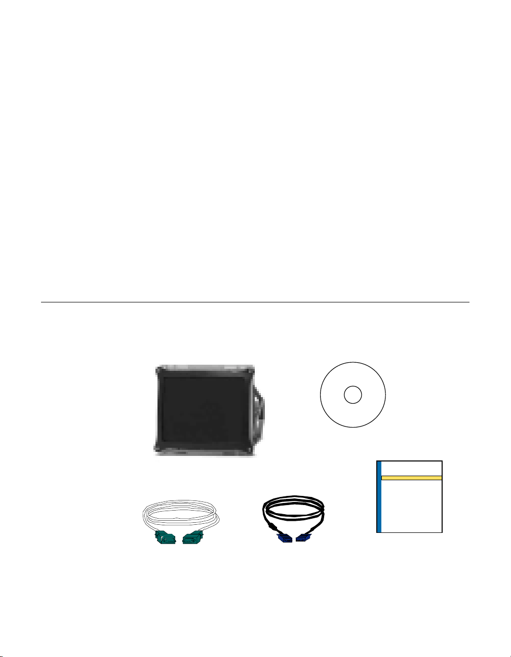
Unpac king Your Touchm onitor
Check that the following 5 items are pres ent and in good condition:
N
OTE
:
Power cord is not included.
C HAPTER
2
S
ETUP
CR T Touchmonitor
Serial cable
VGA cable
CD
Software
CD Software
Quick Installation
Guide
Quick Installation Guide
2-3
Page 11
Conn ecting Your Touchmon itor
I
MPORTANT
:
Before connecting the cables to your touch monitor and PC, be sure that the com puter
and touchmonitor are turned off.
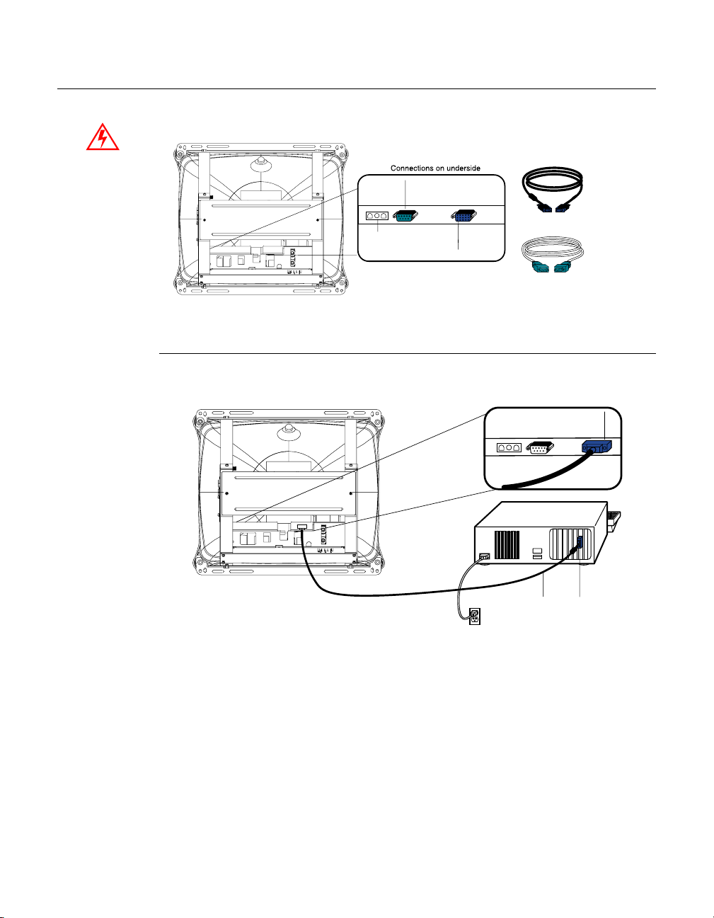
Connect the Video Cable
Power
Female 9-pin serial
touchscreen connector
Female 15-pin
video
connector
Video cable
Serial touchscreen
cable
Connections on underside
Female 15-pin
video
connector
Video
Video cable
port
• Connect one end of the video cable to the video connector on your PC and
the other end of the cable to the video connector on your monitor. Secure the
cable by turning the thumbscrews on each connector.
2-4 Elo Entuitive Touchmonitor User Guide
Page 12
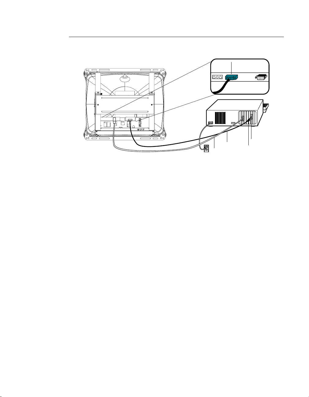
Connect the Serial Touchscreen Cable
Connections on underside
Female 9-pin
cable
connector
Video
port
Ferrite bead
Serial
cable
Video
cable
• Connect the touchscre en cable. Connect one end to the appropriate port on
the back of your computer. Connect the other end of the cable to the
touchscreen connector on your touchmonitor. The touchscreen cable
connectors shoul d fit snugly into the connectors on your touchmonitor and
computer. Secure the cable by turning the thumbscrews on each connector.
2-5
Page 13
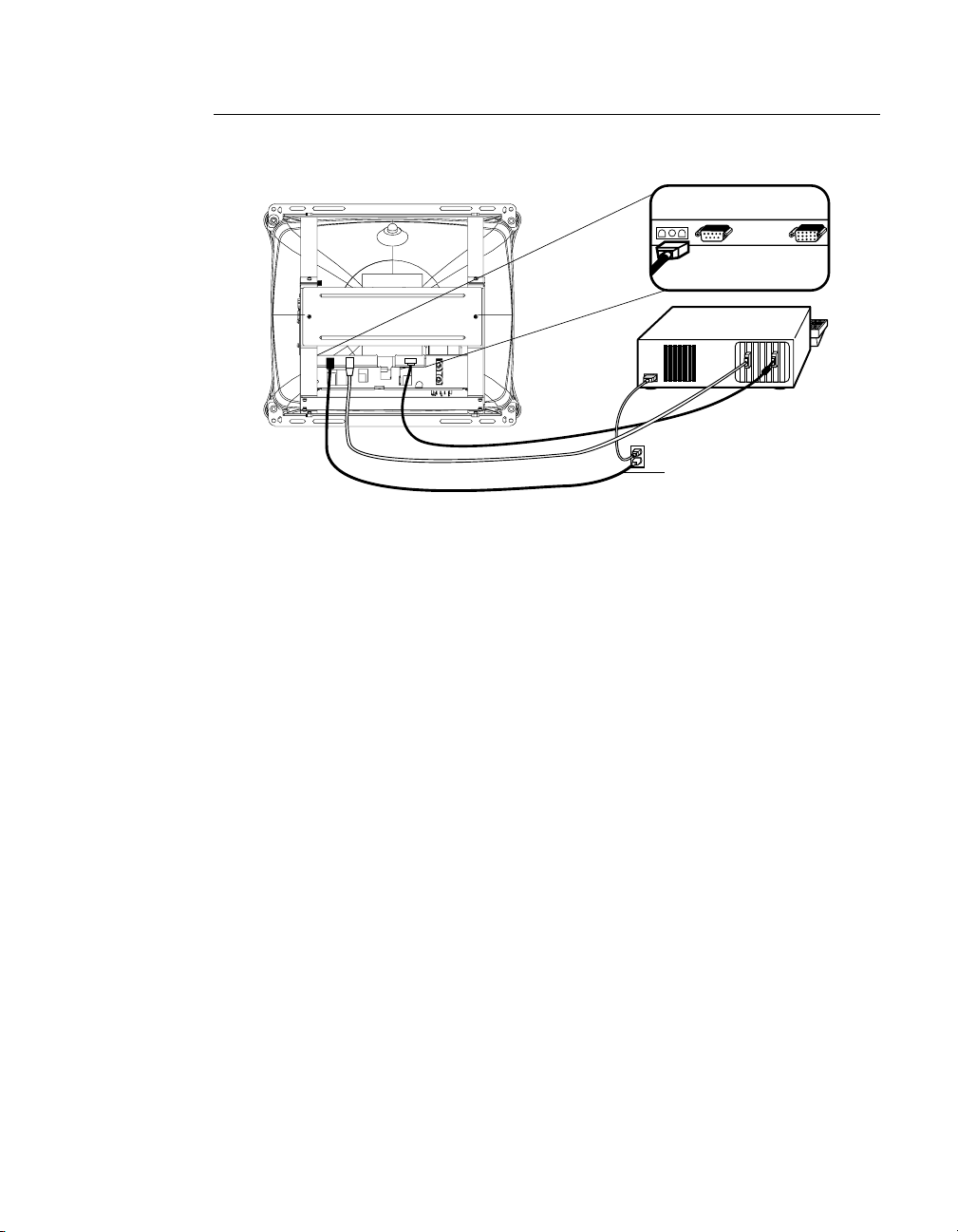
Connect the Power Cable
Connections on underside
Power cable
Power cable
• Your monitor does not include a power cable . You may eit her pur chase a
country specific power cable from Elo (www.elogaming.com), or construct
your own custom power cable (see Appendix B for details). Connect the
power cable to the AC connector on your touchmoni tor. To protect your
equipment against ri sk of damage from electrical surges in the power line,
plug the touchmonitor’s power cord into a switched surge protector, and then
connect the surge prote ctor to a grounded (three-pronged) AC electri cal
outlet.
• Your touchmonitor has no power switch. Power on your monitor using the
power switch of the surg e pro t ecto r, and check t hat th e pow er LED is on. If
not, refer to Chapter 4, Troubleshooting.
• After a brief pause the picture should appear. If necessary, adjust the front
panel controls accor ding to your personal preference (see Chapter 3).
• Insert the Elo TouchTools CD-ROM in your computer’s CD-ROM drive to
install the approp riate touchscreen driver softwar e. Follow the directions
starting on the next page to inst all the driver software.
N
OTE
:
If this monitor is intended to be used in an existing system, the driver software may
already be installed by the system manufacturer. Skip to Chapter 3.
2-6 Elo Entuitive Touchmonitor User Guide
Page 14

Installing the D river Soft ware
Elo TouchSystems provides driver software that allows your touchmonitor to
work with your computer. Drivers a re located on the enclosed CD-ROM for the
following operat ing systems:
• Windows XP
• Windows 2000
• Windows Me
• Windows 98
• Windows 95
• Windows NT 4.0
Additional driver s and driver information for other operating systems are
available on the Elo TouchSystems web site at www.elogaming.com.
Your Elo touchmonitor is plug-a nd-play compliant. Informati on on the video
capabilitie s of your touchmonitor is sent to your video display adapte r when
Windows starts. If Windows detects your touchmonitor, follow the instr uctions
on the screen to install a generic plug-and-play monitor.
Refer to the appropriat e following section for driver instal lation instructions.
2-7
Page 15

N
Installing the T ouch Driver for Windows XP, Windows
20001, Me, 95/98 and NT 4.0
OTE
:
For Windows 2000 and NT 4.0 you must have administrator access rights to install the
driver.
1 Insert the Elo CD-ROM in your computer’s CD-ROM drive.
If the AutoStart feature for your CD-ROM drive is active, the system
automatically de tects the CD and starts the setup program.
2 Follow the directions on the screen to complete the driver setup for your
version of Windows.
If the AutoStart featu re is no t acti ve:
1 Click Start > Run.
2 Click the Browse button to locate the EloCd.exe program on the CD-ROM.
3 Click Open, then OK to run EloCd.exe.
4 Follow the directions on the screen to complete the driver setup for your
version of Windows.
1. To ins tall Windows 2000 and Windows XP, you must use the "update driver" method; you will not
find a setup.exe file within the download.
2-8 Elo Entuitive Touchmonitor User Guide
Page 16

Inst a lling the Touch Driver f o r MS-DO S and
Windows 3. 1
You must have a DOS mouse driver (MOUSE.COM) installed for your mouse
if you wish to continue using your mouse along with your touchmonitor in
DOS.
To install Windows 3.x and MS-DOS from Windows 95/98, follow the
dire c t io ns be lo w:
1 Insert the Elo CD-ROM in your computer’s CD-ROM drive.
2 From DOS, type d:\EloDos_W31 to change to the correct directory on the
CD-ROM (your CD-ROM drive may be mapped to a different drive letter).
3 Type install and press Enter to start the installation.
4 Align the touchscree n.
You must have already completed Steps 1 and 2 before proceeding. Refer to
Chapter 2 of the Elo DOS and Windows Driver Guide as necessary for
additional ins tallation information.
To run the INSTALL program:
1 Type INSTALL at the DOS prompt in the directory containing the driver
inst a l l f i l e s .
2 INSTALL asks you to select the softwar e to install. Then choose
d:\EloDos_W31 from the displ ayed list.
3 INSTALL also asks you for the paths to use during ins tallation, or you may
use its defaults. INSTALL creates directories as necessary, and warns you if
they exist.
If you are updating your softwar e, you may wish to specify the paths conta ining
the earlier versi ons, and overwrite the obsolete files. All ex ecutable programs
are upward comp a tib le. Fo r a list of differences from each prev ious ve rsion of
the drivers, be sure to select "Differences from Previous Versions" during the
installation process.
INSTALL updates your AUTOEXEC.BAT file with the drivers you select.
INSTALL makes a copy of your original AUTOEXEC.BAT file, cal led
AUTOEXEC.OLD. If you already have Elo driver commands in your
AUTOEXEC.BAT file, they will be commented out.
When INSTALL is finished, it leaves a file called GO.BAT in the subdirectory
you specified. GO loads the touchscreen driver, runs the calibration program
ELOCALIB, and gives you some final instructions.
If you are using Windows 3.1, you will also calibrate the touchscreen within
Windows 3.1 with the Touchscreen Control Panel.
2-9
Page 17

2-10 Elo Entuitive Touchmonitor User Guide
Page 18

About T ouchmonitor Adjustments
By design, your El o Entui tive touchm onitor sh ould not requi re any adjust ments.
The factory setti ngs will give you optimum video r esults with most standar d PC
video display adapters.
However, after connecting your touchmonitor you can further optimiz e the
settings to meet your requir ements by following the directions in this chapter.
C HAPTER
3
C
HAPTER
3
O
PERATION
I
MPORTANT
All adjustments you make to the controls are automatically memorized, so you
do not need to reset your choices every time you unplug your touchmonitor or
power it off and on. If there is a power failure your touchmonitor settings will
not default to the factor y specif ications.
:
Do not insert conductive metal objects into the monitor's circuitry. The monitor uses high
voltages and the metal edges can be sharp. Disassembly or realignment of the monitor
circuitry voi ds the warranty.
3-11
Page 19

Touchmo nitor Con tr ols
You can adjust t he scre en displ ay by usi ng the plast ic knob l abeled OS D locate d
on the right-hand side of the touc h controller bracket.
Using the On Screen Display (OSD)
1 Push the OSD knob to access the OSD.
2 Turn the OSD knob to choose the ite m you want to adjust. The selected item
is highlighted. See figure 3.1 for OSD menu options.
3 Push the OSD knob to adjust the highlighted item.
The display unit automatic ally saves the new settings in about 45 seconds
after your last adjustm ents. The menu will automatically disappear or you
can push the OSD knob to make the menu disappear.
EXIT
R
Figure 3.1
3-12 Elo Entuitive Touchmonitor User Guide
OSD Menu
RGB
OSD
Page 20

OSD Adju stments
Symbol Function Process
H. Size
H. Position
Adjusts the horizont al size of the entire scre en image.
Adjusts the horizont al position of the entire screen image.
V. Size Adjusts the vertica l size of the entire scre en image.
V. Position
Zoom
Geometry
Pincushion
Trapezoid
Adjusts the vertical position of the entire screen image.
Simultaneously changes vertical and horizontal image size.
See Figure 3.4, page 3-16.
If the vertical sides of the picture curve in or bulge ou t, you
can correc t the distortion by using the pincushion adjustment.
If the picture is wider at the top or at the bottom, you can
correct the distortion by using the trape zoid adjust me nt.
Parallel
Pin
Balance
Top
Corner
Bottom
Corner
If the sid es of th e sc re en imag e ar e ti lted, you can co rr ec t the
distortion by using the parallel adjustment.
If the sides of the pic ture are bow ed to t he right or the left, you
can correc t the pin cushion balance by usin g this adjustm ent.
Eliminates top corner distortion.
Eliminates bottom corner distortion.
3-13
Page 21

S. Correct
Corrects vertical center linearity.
C. Correct
V. Moire
H. Moire
Language
Rotation
Input Level
OSD,
H. Posit ion,
V. Position
Timeout
Corrects vertical top and bottom linearity.
Clears vertical moire if a series of concentric circles or arcs
appear on your screen.
Note: Moire i s an int er fa ce patt er n th at ma kes the scr een see m
to have faint lines. A picture that is rastered or consists of
small repeating figures is sensitive to moire interference.
Stron g co lors are also liab le to in tensify m o ir e. The moire
pattern on the screen does not affect the printout of the image.
Clears horizontal moi re if a series of concentric circles or arcs
appear on your screen.
You can selec t the language in w hich adjustmen t m enus are
displayed. The following languages are available; Engl ish,
German, French, Italian, and Spanish.
If the entire screen image is tilted, you can correct the
distortion by using the rotation adjustment.
Selects video input level 0. 7V p-p or 1.0 Vp-p.
(Figure 3.2) Adjusts the horizontal and vertical position of the
OSD window and determines how long (in seconds) the OSD
menu waits bef ore closing au tomatically wh en no action has
been performed.
Color
Temp
Save
Recall
Status
3-14 Elo Entuitive Touchmonitor User Guide
(Figure 3.3) To correct the color te mp eratures individually,
use the red, green, and blue contrast and brightness
adjustments. To confirm the setting press the menu again.
Saves current setting.
Recalls factory settings of the image parameters .
Displays t he horizontal and vertical frequency settings from
the co m p u ter.
Page 22

If you have moved the display uni t, you should perform
demagneti zation. Demagnetizing takes place automatically
when the disp lay unit is switched on, and the unit normally
mainta in s faultless color purity du ring oper ation.
Degauss
If you have tilted, swivel ed or moved the display unit , you can
perform demagnetization. During th e process the picture is
distorted for a few second s. After demagnetization, the color
impurities have disappeared if caused by stray magnetic fields.
Do not use the dega uss fea ture more th an once eve ry ha lf hour
or the degaus s function will not work.
Brightness Adjusts the brightness of the scr e en.
Contra st
Adjusts the contrast of the screen.
3-15
Page 23

Figure 3.2
Figure 3.3
ESC
OSD
OSD
ESC
9300
6500
Figure 3.4
3-16 Elo Entuitive Touchmonitor User Guide
ESC
Page 24

C HAPTER
4
C
HAPTER
4
T
ROUBLESHOOTING
Problem Suggestion (s)
No picture. Your touchmonitor may not be getting power.
Touchmonitor does not ent er power
management mode.
Screen fl ickers The screen may seem to flic ker when the refresh
Color defects If your colo r is not uniform , degauss the
Picture appears to be gho sting. Make certa in there is a good connection between
Picture is not centered. Read about adjusting your touchmonitor picture
Make certa in that your p ow er strip is plugged into
the wall so cket and that the PC and touchmonit o r
are plugged in and powered on.
Test the pow er supp ly by tryi ng di ffer en t ca bles or
a different wall outlet, or by plugging another
applian ce into the outlet.
If the monitor's LED is slowly flashing, the
monitor is in standby mode. Push one of the
keyboard keys. Check that the keyboard is
properly connected to t he computer.
Ensure that your computer and video card are
properly configured (consult the video card
documentation).
The video signal from the comp uter does not
comply with VESA DPMS standard. Either the
computer or the graphics adapter is not using the
VESA DPMS power ma nagement function.
rate is less than 75Hz. See the list of recommended
modes in Appendix C, page 23.
touchmoni tor as descri bed in Chapter 3, page 15,
and make sure that the touchmonitor is at least 12
inches fr om any other electrical equipment.
the touch m onitor and the com puter.
and make the appropriat e adjustments.
4-17
Page 25

Problem Suggestion (s)
Picture appears “washed out”. Readjust your brightne ss and contrast settings.
Picture not present or severely
distorted.
Duplicated images A problem with your graphics adapter or
"NO SIGNAL" window appears. The monitor is receiving no video signal from the
"SIGNAL OUT OF RANGE" window
appears.
Touch doesn’t work. Check to make sure the touchscreen cable is
Verify that your video display adapter settings ar e
formatted for the correct resol u tion and vert ical
refres h rates.
touchmoni tor. Contact your service representative.
PC. Ensure the PC is plugged in, tur ned on, and
the video cable is connec ted.
The mon itor is rec eiving a video sig n alwhich is
beyond the limits of its capability. Change the
PC's video display adapter settings to agree with
one of the display modes give n in Appendix C.
securel y attached at both ends.
4-18 Elo Entuitive Touchmonitor User Guide
Page 26

Touchscreens: An Ov erview
Typically, users communicate with computers by using a mouse, a keyboard, or
a combination of the two. Users who are not keyboard- literate or mouse-savvy
can become frustrated with how long human-to-computer interactions take.
Computer literac y is learned. This is complicated by the fact that using a
keyboard or a mouse is neither intuitive nor natural for most people.
Touchscreens cut out the le arning curve by eliminating keyboard/mous e
intermediaries and allowing a natural flow of information to develop between a
user and a comput er.
C
HAPTER
4
T
OUCH
A PPENDIX
A
T
ECHNOLOGY
When a user wants to access information or perform a function on a computer
with a touchscreen installed, a touch quickly and accurately does the job that
once required complica ted keyboard interactions or preci se mouse movements.
A frustrating expe rien ce w ith a co mp ut er d uri ng a tran s acti o n can cre ate
dissatisfaction for your customer. Touchscreens help eliminate unpleasant
transactions by creating a natural flow of information that enhances your
product or service. Touchscreens speed up user/computer inter actions. People
get what they wan t faster and are more satisfied with the p roces s.
A-19
Page 27

iTouch Touchscreens
Elo built on its Intelli Touch surface wave technology to create its iTouc h
"touch-on-tube " solution. Elo eliminated the clea r glass layer between the
viewer and the di splay. iTo uch touchm onitors have been adopted b y so me of t he
largest manufact urers in the world in their next generation games.
Elo CRT gaming monitors offer consiste nt features across all sizes:
• Touch directly on tube—no touchsc reen overlay and no parallax.
• Preserves 100 percent of CRT brightness, clarity, antireflection and color
properties.
• More durable and safer than even bonded touchscreen overlays.
• Same fast, accurate, stable performance as Elo’s IntelliTouch surface wave
touchscreen overlays.
• "Drift free" and not affecte d by surrounding metal or poor earths/grounding.
• Dual touch es are not averaged, allowi ng extr eme ly fas t two-h a nde d pl ay .
• Z-axis for pressure can add a new dimension to games.
• No need for peri od ic recali b rati on.
A-20 Elo Entuitive Touchmonitor User Guide
Page 28

C
HAPTER
4
T
OUC HMON ITOR
A PPENDIX
B
S
AFET Y
DANGER
As this equipmen t is receiv ed it pres ent s an electri ca l sh ock haz ard that co uld
result in serio us injury or death. Only qualif ied perso ns should work aroun d this
equipment when it is energiz ed. This equ ipment is intended to be used by a
manufacturer only for building-in to other equipment which will provide a
proper electric al and fire safety enclosure.
This manual contains inf ormation that is important for the proper setup and
maintenance of your touc hmonitor. Befor e setti ng u p and poweri ng on your new
touchmonitor, read through this manual, especially Chapter 2, I nstallation and
Setup, and Chapter 3, Operation.
1 To reduce th e risk of electric shock, follow al l safety notices and never insert
conductive metal objec ts into the circuitry.
2 It is important that your touchmonitor remains dry. Do not pour liquid int o or
onto your touchmonitor . If your touchmo nitor becomes wet do not attempt to
repair it yourself.
3 Your new monitor is equipped with a three-wire, grounding power connector,
AMP "Mate-N-Lock", part number 350767-1. Contacts inside the connector
are female type, AMP part number 350550-1.
Connector I nformation
Pin 1 Mains line hot monitor (b rown )
Pin 2 Mains ground monitor (green)
Pin 3 Mains line neutral monitor (blue)
B-21
Page 29

Note:
Should you wish to construct your own custom power cable, Elo highly
recommends using AMP "Mate-N-Lock" part number 350766-1 and male
type contacts, AMP part number 350547-1.
After connect ing the power cable to the monitor, but before a pplying power,
ensure that the power cable’s black or brown wire connects to the monitor’s
brown wire; the power cable’s green wire connects to the monitor’s green
wire; and the power cabl e’s white or blue wire connects to the monito r’s blue
wire.
The cable used m ust include a green (earth ground ) wire, it must be 18AWG (or larger),
and it should be rated SVT 105C 600V (or better).
B-22 Elo Entuitive Touchmonitor User Guide
Page 30

C
HAPTER
4
T
ECHNICAL
N
OTE
:
All specifications are subject to change.
Touchmon itor Spe cifications
19"Monitor 17" Monitor 15" Monitor
A PPENDIX
C
S
PECIFICATIONS
Picture Tube
Maximum
Resolution
Deflection
Frequency
Maximum Video
Input Bandwidth
Display Area*
Input Signal
Input Voltage
Display Colors*
*Dependent on video controller/card used.
19” (18” di agonal viewable
image), 0.25-mm dot pitch.
640x350/70Hz
720x400/70Hz
640x480/60, 72, 75, 85HZ
800x600/56,60,72,75,85HZ
1024x768/ 60, 70, 75, 85Hz
1280x1024/60Hz
Non-interlaced
Horizontal: 30-70 kHz
Vertical: 50-160 Hz
100 MHz 100 MHz 65 MHz
H: 360 mm
V: 270 mm
R.G.B. Analog, 15 pin D-sub R.G.B. Analog, 15 pin D-sub R.G.B. Analog, 15 pin D-sub
100-240 VAC, 50-60 Hz 100-240 VAC, 50-60 Hz 100-240 VAC, 50-60 Hz
Analog input; unlimited
colors
17” (15. 7” diagonal
viewabl e image), 0.27-m m
dot pitch.
640x350/70Hz
720x400/70Hz
640x480/60, 72, 75, 85HZ
800x600/56,60,72,75,85HZ
1024x768/ 60, 70, 75, 85Hz
1280x1024/60Hz
Non-interlaced
Horizon tal: 30-70 kHz
Vertic al: 50-160 Hz
H:300 mm
V: 225 mm
Analog input; unlimited
colors
15” (13. 8” diagonal
viewabl e image), 0.28-m m
dot pitch..
640x350/70Hz
720x400/70Hz
640x480/60, 72, 75, 85HZ
800x600/56,60,72,75,85HZ
1024x768/60Hz
Horizon tal: 30-55 kHz
Vertic al: 50-160 Hz
H: 270 mm
V: 202 mm
Analog input; unlimited
colors
C-23
Page 31

19"Monitor 17" Monitor 15" Monitor
Typical Power
75 watts 65 watts 60 watts
Consumption
Power
Manageme nt
Plug a nd P la y
Compatibility
Compliant with EPA/Energy
Star, VESA DPMS signaling
method.
Compliant with VESA DDC
1/2B standards.
CRT Life Average operational CRT
life is 12, 000 hours to half
brightness.
On-Screen
Adjustments
Safety
Bright ne ss , C on t ra st, Exit,
Zoom, V.Size, V. Positio n,
H. Size, H. Position,
Language, Save, Recall,
Starus, Degauss, Rotation,
Input L e vel, OSD, C o lor
Temperat ure, Trapezoid,
Parallel, Pin Balance, Top/
Bottom Corner, S/C Correct,
H/V Moire.
cRUus, DHHS, TÜV cRUus, DHHS, TÜV cRUus, DHHS, TÜV
Regulations
EMC
MPRII, FCC Class B, CE MPRII, FCC Class B, CE FCC Class B, CE, MPRII
IC ES-003
C-Tick
VCCI
Monitor
424w x 440d x 375h 397w x 405d x 343h 424w x 440d x 375h
Dimensions
Net Weight
Operating
Temperature
Humidity
17.8kg 14.7kg 11.7kg
5-55°C 5-55°C 5-55°C
10%-80% 10%-80% 10%-80%
Compli an t wi th EPA/ Ener gy
Star, VESA DP MS si gnali ng
method.
Compliant with VESA DDC
1/2B standards.
Average operation al CRT
life is 12, 000 hours to half
brightness.
Brightness, Contrast, Exit,
Zoom, V.Size, V. Position,
H. Size, H. Position,
Language , Save, Recall,
Starus, Degauss, Rotation,
Input Level, OSD, Color
Temperature, Trapezoid,
Parallel, Pin Balance, Top/
Bottom Corner, S/C Correct ,
H/V Moire.
Compli an t wi th EPA /E ne rgy
Star, VESA DP MS si gnali ng
method.
Compliant with VESA DDC
1/ 2B standards.
Average operation al CRT
life is 12, 000 hours to half
brightness.
Brightness, Contrast, Exit,
Zoom, V.Size, V. Position,
H. Size, H. Position,
Language , Save, Recall,
Starus, Degauss, Rotation,
Input Level, OSD, Color
Temperature, Trapezoid,
Parallel, Pin Balance, Top/
Bottom Corner, S/C Correct ,
H/V Moire.
C-24 Elo Entuitive Touchmonitor User Guide
Page 32

Table C.1
iTouch Touchmonitor Specifications
Mechanical
Positional Accuracy Standard deviation of error is less than 0. 080 in. (2.03 mm). Equates to less
Touchpoint Density More than 100, 000 touchpoints/in
Touch Activ ation Force Typically less than 3 ounce s (85 grams).
Surface Dur ability Surface durability is that of glass, Mohs’ hardness rating of 7.
Expected Life
Performance
Sealing Unit is sealed to protect against splashed liquids, dirt , and dust.
than ±1% .
No known wear-out mechanism, as there are no la yers, coatings, or moving parts.
iTouch tec hnology has been operationally tested to more than 50 million touches in
one location w ithout failure, using a stylus similar to a finger.
2
(15,500 touchpoints/cm2).
Optical
Light Transmission (per
ASTM D1003)
100%
Environmental
Chemica l Resistance The active area of th e touchscreen is resis tant to all chemicals that do not affe ct
glass, su ch as:
Acetone
Toluene
Methyl ethy l ketone
Isopropyl alcohol
Methyl alco hol
Ethyl acetate
Ammonia-based glass cle aners
Gasoline
Kerosene
Vinegar
Electrostati c P r o te ct io n
(per EN 61 000-4-2, 1995)
Meets Level 4 (15 kV air/8 kV contact dischar ges).
C-25
Page 33

Signal PI NOUT for 15",17
PIN Number Signal
1 Red video
2 Green video
3Blue video
4Ground
5 *VGA card detection (GND)
6 Red return
7 Green return
8Blue return
9NC
10 Sync return
11 Ground
12 S DA (S e ria l D a ta)
13 Horizontal Sync
14 Vertical Sync
15 SCL (Serial Clock)
" and 19"
7 6810 9
Monitor s
12345
1113 1215 14
*Pin 5, sel f-test pin shall be grounded when signal connector is plugged in.
C-26 Elo Entuitive Touchmonitor User Guide
Page 34

P o we r Cons umpt ion
The touchmonitor comes with a power-saving feature that controls its power
consumption. This feature complies with both the EPA’s Energy Star
requirements. It also conforms to the Display Power Management System
(DPMS) power-down signaling method a pproved by the Video Electronics
Standard Association (VESA).
Mode LED
Normal Green 60
Standby Green/ blinking 15
Suspend Green/ blinking 15
Off Green/ blinking 5
Unplugged Not illuminated 0
15" Monitor
Power
consum p t ion (W)
17" Monitor
N
Mode LED
Normal Green 65
Standby Green/ blinking 15
Suspend Green/ blinking 15
Off Green/ blinking 5
Unplugged Not illuminated 0
consum p t ion (W)
19" Monitor
Power
Power
Mode LED
Normal Green 75
Standby Green/ blinking 15
Suspend Green/ blinking 15
Off Green/ blinking 5
Unplugged Not illuminated 0
OTE
:
The only w ay to isolat e the display unit completely from the mains supply is to unplug the
main s c able.
consum p t ion (W)
C-27
Page 35

Preset Timing Table
Your Elo Entuitive touchmon itor has 5/4 preset timing modes. The following
are modes preset as factory defaults:
No. Resolution
1 640x400 31.5 kHz 70 Hz
2 640x480 31.5 kHz 60 Hz
3 640x350 31.5 kHz 70 Hz
4 800x600* 53.7 kHz 85 Hz
5 1024x768* 68.7 kHz 85 Hz (17" and 19"
*Recommended primary mod e
Horizontal
Frequency R efresh Rate
only)
C-28 Elo Entuitive Touchmonitor User Guide
Page 36

C
HAPTER
4
R
EGULATORY INFORMATION
Electrical Safety Info r mation
A) Compliance is required with respect to the voltage, frequency, and current
requirements indicated on the manufacturer’s label. Connection to a different
power source than those specified herei n w ill likely result in improper operation or
damage to the equipm ent, or may pose a fire hazar d if the l imitations are exceeded.
B) There are no operator serviceable parts inside this equipment. This equipment
genera tes hazardou s voltages that co nstitute a safety h azard. Servi ce should be
provided only b y a qu alified service technician.
C) This equipment is provided with a detachable power cord that has an integral
safety ground wire and three-prong connector intended for connection to a
grounded s afety outlet.
1) D o no t su bs titute the co rd with a ny c o rd ot he r than t he provi d ed approved
type. Under no circumstances use an adapter plug to connect to a two-wire
outlet, as t his will defeat the continuit y of the groundin g w ire.
2) This equipment requires the use of the ground wire as a part of its safety
certification. Modification or misuse can provide a shock hazard that can
result in serious injury or death.
3) If there are any questions about the installation prior to connecting the
equipment to mains p ower, contact a qualified electrician or the m anufacturer.
Emissions and Immunity Information
A) Notice to Users in the United States: This equipment has been tested and found
to com p ly with Par t 15 C la ss B of F C C R u l es f or digi ta l devices. These limits are
designed to provide reasonable protection against harmful interference in a residential installati on. This equipme nt generates, uses, and can radiate radio
frequen cy energy, and if not installed and used in accordance with the instructions,
may cause harmful interference to radio communications.
B) Notice to Users in Canada: This equipment has been tested and found to
comply with Class B radio noise emission limits as established by the Radio
Interference Regul ations of Industrie Canada for digital devices.
C) Notice to Users in the European Union: This equipment has been tested and
found t o comply w ith the Class B require ments of CE marking fo r Informati on
Technology Equipment as required by: Low Voltage Directive 73/23/ECC and
standard EN 60950; EMC Directive 89/336/ECC, and per standard EN 55022.
D) General Information to All Users: This equipment generates, uses, and can
radia te radi o fre qu enc y ene rgy. If not in stal le d and used acc or din g to t his man ual ,
the equipment may cause interference with radio and television communications.
There is, however, no guarantee that interference will not occur in any particular
instal lation due to site-specific factors.
29
Page 37

1) In order to meet emission and immunity requirements, the user must
observe the following:
a) Use only the provided I/O cables to connect this digital device with
any computer.
b) To ensure compliance, use only the provided manufacturer-approved
line cord.
c) The user is cautioned that changes or modifications to the equipment
not expressly approved by the party responsible for compliance could
void the user’s authority to operate the equipment.
2) If this e quipment ap pears to c ause interference with radio or tel evision
reception, or any other device:
a) Verify as an emission source by tur ning the equip me nt off and on.
b) If you de te r m in e th a t th is equ i pm e n t is cau s in g the int er fe rence, tr y to
correct the interference by using on e or m ore of the following measures:
i) Move the digital device away from the affected receiver.
ii) Reposition (turn) the digital device with respect to the affected
receiver.
iii) Reorient the affected rece iver’s antenna.
iv) Plug the digital device into a different AC outlet so the digital
device and the receiver are on different branch circuits.
v) Disconnect and remove any I/O cables that the digital device
does not use. (Unterminated I/O cables are a potential source of
high RF emission levels.)
vi) Plug the digital device into only a grounded outlet receptacle.
Do not use AC adapter plugs. (Removing or cutting the line cord
ground may increase RF emission levels and may also present a
lethal shock hazard to the user.)
If you need add itional help, consult your dealer , m anufacture r, or an
experienced radio or television technician
E141667
30 Elo Entuitive Touchmonitor User Guide
DHHS
Page 38

C
HAPTER
4
W
ARRANTY
Except as otherwise stated herein or in an order acknowledgment delivered to
Buyer, Seller warrants to Buyer that the Product shall be free of defects in
materials and workmanship. With the except ion of negotiated warr anty perio ds,
the warranty for the touchmonitor and components of the product is 2 years.
Seller makes no warranty regarding the model life of components. Seller’s
suppliers may at any time and from time to time make change s in the
components deliver ed as Products or components.
Buyer shall notify Seller in writing promptly (and in no case later than thirty
(30) days after discov ery) of the failure of any Product to conform to the
warranty set forth above; shall describe in commercially reasonable detail in
such notice the symptoms assoc iated with such failure; and shall provide to
Seller the opportun ity to inspect such Products as installed, if possible. The
notice must be received by Selle r during the Warranty Period for such product,
unless otherwise directed in writing by the Seller. Within thirty (30) days after
submitting such noti ce, Bu yer shall package the allegedly defective Product in
its original ship ping carton(s) or a functional equivalent and shall ship to Seller
at Buyer’s expense and risk.
Within a reasonable time after receipt of the allegedly defective Product and
verification by Seller that the Product fai ls to meet the warranty set forth above,
Seller shall corr ect such failure by, at Seller’s options, either (i) modifying or
repairing t he Product or (ii) replacing the Product. Such modification, repair, or
replacement and the return shipment of the Pro duct with minimum insurance to
Buyer shall be at Se ller’s expense. Buye r shall be ar the r isk of loss or damage in
transit, and may insure the Product. Buyer shall reimburse Seller for
transportat ion cost incurred for Product returned but not found by Selle r to be
defective. Modifi cation or repair , of Products may, at Seller’ s option , take place
either at Seller ’s facilities or at Buyer’s premises. If Seller is unable to modify,
repair, or replace a Product to conform to the warranty set forth above, then
Seller shall, at Seller’s option, either refund to Buyer or credit to Buyer’s
account the purchase price of the Product less depreciation calculated on a
straight-line basis over Seller’s stated Warranty Period.
31
Page 39

THESE REMEDIES SHALL BE THE BUYER’S EXCLUSIVE REMEDIES
FOR BRE ACH OF WARRANTY. EXCE PT FOR THE EXPRESS
WARRANTY SET FORTH ABOVE, SELLER GRANTS NO OTHER
WARRANTIES, EXPRESS OR IMPLIED BY STATUTE OR OTHERWISE,
REGARDING THE PRODUCTS, THEIR FITNESS FOR ANY PURPOSE,
THEIR QUALITY, THEIR MERCHANTABILITY, THEIR
NONINFRINGEMENT, OR OTHERWISE. NO EMPLOYEE OF SELLER
OR ANY OTHER PARTY IS AUTHORIZED TO MAKE ANY WARRANTY
FOR THE GOODS OTHER THAN THE WARRANTY SET FORTH
HEREIN. SELLER’S LIABILITY UNDER THE WARRANTY SHALL BE
LIMITED TO A REFUND OF THE PURCHASE PRICE OF THE PR ODUCT.
IN NO EVENT SHALL SELLER BE LIABLE FOR THE COST OF
PROCUREMENT OR INSTALLATION OF SUBSTITUTE GOODS BY
BUYER OR FOR ANY SPECIAL, CONSEQUENTIAL, INDIRECT, OR
INCIDENTAL DAMAGES.
Buyer assumes the risk and agrees to indemnify Seller against and hold Seller
harmless from all liability relating to (i) assessing the suitability for Buyer’s
intended use of the Product s and of any system design or drawing and (ii)
determining the complia nce of Buyer’s use of the Products with applicable
laws, regulations, codes, and standards. Buyer retains and accepts full
responsibil ity for all warranty and other claims relatin g to or arising from
Buyer’s products, which include or incorporate Products or components
manufactured or supplied by Seller. Buyer is solely responsible for any and all
representations and warranties regarding the Products made or authorized by
Buyer. Buyer will indemnify Seller and hold Seller harmle ss from any liability,
claims, los s, cos t, or expe nses (inc lu ding rea sonable a tto rney’s fees) a ttribu table
to Buyer’s products or representations or warranties concerning same.
32 Elo Entuitive Touchmonitor User Guide
Page 40

Index
A
About the Product, 1
About Touchmonitor Adjustments, 11
B
Bottom Corner, 13
Brightness, 15
C
C. Correct, 14
Chemical Resistance,25
Color Control, 14
Connect the Power Cable, 6
Connect the Serial Touchscreen Cable, 5
Connect the Video Cable,4
Connecting Your Touch m onitor,4
Connector Infor mation, 21
Contrast, 15
CRT Life, 24
D
Deflection Frequency,23
Displa y Area, 23
Display Colors, 23
E
Electrical Safety Information, 29
Electrostatic Protec tion, 25
EMI, 24
Emissions and Immunity Information, 29
Expecte d Li fe P erforma nc e, 25
G
Geometry, 13
H
H. Moire, 14
H. Position, 13
H. Size, 13
Humidity, 24
I
Input Level, 14
Inpu t Signal,23
Inpu t Voltage,23
Installing the Driver Software, 7
Installing the Serial Touch Driver for MS-DOS and
Windows 3.1, 9
Installing the Touch Driver for Windows XP, Windows
2000, M e, 95/98 an d NT 4.0, 8
Intelli Touch Touc hm onitor Spe c if i ca tio ns , 25
iTouch Touchscreens, 20
L
Language, 14
Light Transmission,25
M
Maximum Resolution, 23
Maximum Video Input Bandwidth, 23
Monitor Dimensions, 24
N
Net Weight, 24
O
On-Screen Adjustments, 24
Operating Temperature, 24
Operation, 11
OSD Adjustments,13
OSD, H. Position, V. Position Timeout, 14
P
Parallel, 13
Picture Tube, 23
Pin Balance, 13
Pincushion, 13
Plug and Play Compatibility, 24
Posit i on al A c cu r ac y , 25
Power Consumption, 24, 27
Power Management, 24
Precautions, 1
Preset Mo de s , 27
Preset T im in g Table, 28
R
Recall, 14
Regulatory Information, 29
Rotation, 14
Index-33
Page 41

S
S. Correct, 14
Safety Regulations, 24
Save, 14
Sealing, 25
Signal PINOUT for 15” and 17” Monitors, 26
Solutions to Common Problems, 17
Status, 14
Surfac e Dur a bi lity, 25
T
Technical Specifications, 23
Top Cor ner, 13
Touch Activation Force, 25
Touchmonitor Controls, 12
Touchmonitor Safety, 21
Touchmonitor Specifications, 23
Touchp oi nt D en si ty , 25
Touchscreens
An Overview, 19
Trapezoid, 13
Troubleshooting, 17
U
Unpacking Your Touchmonitor, 3
Using the On Screen Display (OSD), 12
V
V. Moire, 14
V. Position, 13
V. Size, 13
W
Warranty, 31
Z
Zoom, 13
Index-34
Page 42

 Loading...