

Elo TouchSystems IntelliTouch SecureTouch, IntelliTouch Series, SecureTouch Series User Manual
Page 1
Page 2

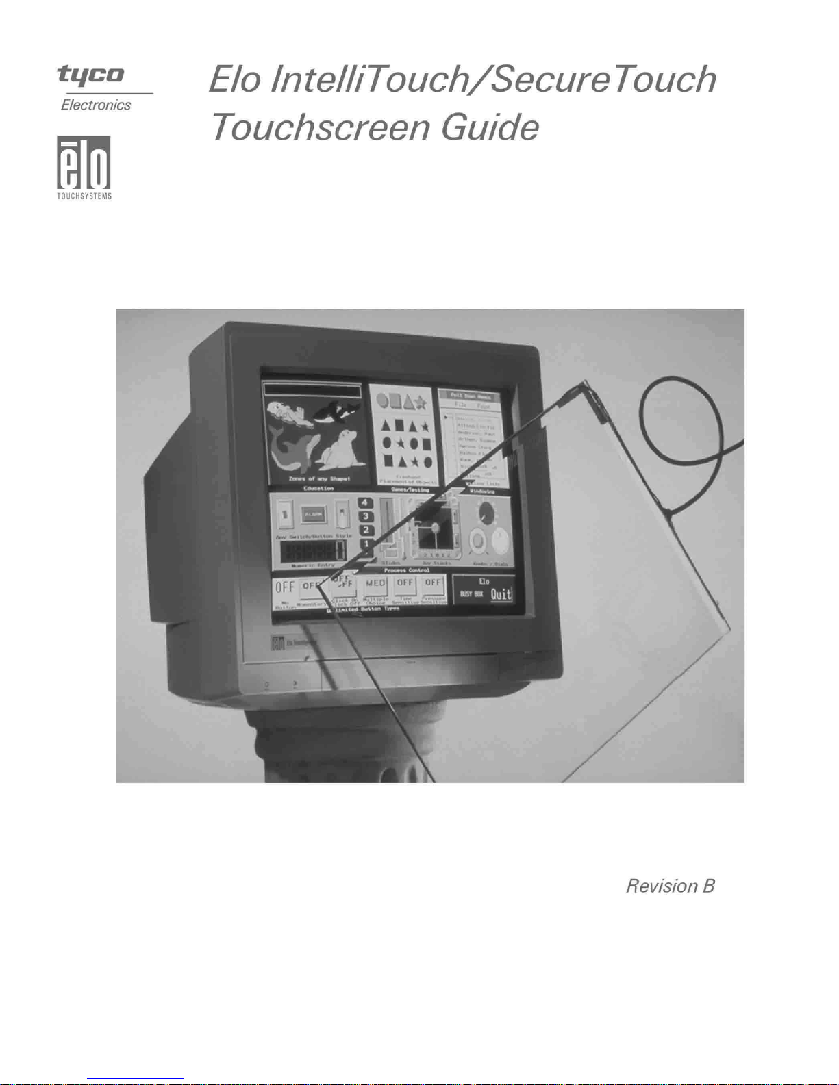
Elo IntelliTouch®/SecureTouch
Touchscreen Guide
Revision B
P/N 0082 12M
Elo TouchSystems, Inc.
1-800-ELOTOUCH
www.elotouch.com
Page 3

Copyright © 1989, 1992, 1995, 1996, 2001 Elo TouchSystems Inc.
All Rights Reserved.
No part of this p ublic ation ma y be repr oduce d, tra nsmitte d, transc ribe d, stor ed in a ret rieval system,
or translated into any langu age or computer language, in any form or by any means, including, but not
limited to, electronic, magnetic, optical, chemical, manual, or otherwise without prior written permission of Elo TouchSystems.
Disclaimer
The informat ion in this docum ent is subje ct to change with out notice . Elo TouchSystems make s no
representations or warranties with respect to the contents hereof, and specifically disclaims any
implied warranti es of mer chanta bilit y or fitness for a parti cular purp ose. El o TouchSystems rese rves
the right to rev ise th is pu blic a tio n and to mak e ch ang e s fr om t im e to t im e in the c o nten t h er eof w i thout obli gation of Elo TouchSystems to not ify any person of such revi s ions or changes.
Trademark Acknowledgments
iTouch, IntelliTouch, SecureTouch, AccuTouch, Entuitive, MonitorMouse, ELODEV, and SmartSet
are trademarks of Elo TouchSystems, Inc.
Other product names mentioned herein may be trademarks or registered trademarks of their respective companies. Elo TouchSystems claims no interest in trademarks other than its own.
i
Page 4

ii
Page 5

C
HAPTER
0
I
NTELLITOUCH
Except as otherwise stated herein or in an order acknowledgment delivered to
Buyer, Seller warrants to Buyer that the Product shall be free of defects in
materials and workmanship. The warranty for IntelliTouc h touchs creens is 10
years and for IntelliTouch controllers 5 years.
Seller makes no warranty regarding the model life of components. Seller’s
suppliers may at any time and from time to time make changes in the
components deliver ed as Products or components.
Buyer shall notify Seller in writing promptly (and in no case later than thirty
(30) days after discov ery) of the failure of any Product to conform to the
warranty set forth above; shall describe in commercially reasonable detail in
such notice the symptoms assoc iated with such failure; and shall provide to
Seller the opportun ity to inspect such Products as installed, if possible. The
notice must be received by Seller during the Warranty Period for such product,
unless otherwise directed in writing by the Seller. Within thirty (30) days after
submitting such noti ce, Bu yer shall package the allegedly defective Product in
its original ship ping carton(s) or a functional equivalent and shall ship to Seller
at Buyer’s expense and risk.
Within a reasonable time after receipt of the allegedly defective Product and
verification by Seller that the Product f ails to meet the warranty set for th above,
Seller shall corr ect such failure by, at Seller’s options, either (i) modifying or
repairing t he Product or (ii) rep lacing the Product. Such modification, repair, or
replacement and the return shipment of the Product with minimum insurance to
Buyer shall be at Se ller’s expense. Buye r shall be ar the r isk of loss or damage in
transit, and may insure the Product. Buyer shall reimburse Seller for
transportat ion cost incurred for Product returned but not found by Seller to be
defective. Modifi cati on or repair, of Products may, at Seller’ s option , take place
either at Seller ’s facilities or at Buyer’s premises. I f Seller is unable to modify,
repair, or replace a Product to conform to the warranty set forth above, then
Seller shall, at Seller’s option, either refund to Buyer or credit to Buyer’s
account the purchase price of the Product less depreciation calculated on a
straight-line basis over Seller’s stated Warranty Period.
10-Y
EAR
W
ARRANTY
iii
Page 6

THESE REMEDIES SHALL BE THE BUYER’S EXCLUSIVE REMEDIES
FOR BRE ACH OF WARR ANTY. EXCE PT FOR THE EXPRESS
WARRANTY SET FORTH ABOVE, SELLER GRANTS NO OTHER
WARRANTIES, EXPRESS OR IMPLIED BY STATUTE OR OTHERWISE,
REGARDING THE PRODUCTS, THEIR FITNESS FOR ANY PURPOSE,
THEIR QUALITY, THEIR MERCHANTABILITY, THEIR
NONINFRINGEMENT, OR OTHERWISE. NO EMPLOYEE OF SELLER
OR ANY OTHER PARTY IS AUTHORIZED TO MAKE ANY WARRANTY
FOR THE GOODS OTHER THAN THE WARRANTY SET FORTH
HEREIN. SELLER’S LIABILITY UNDER THE WARRANTY SHALL BE
LIMITED TO A REFUND OF THE PURCHASE PRICE OF THE PR ODUCT.
IN NO EVENT SHALL SELLER BE LIABLE FOR THE COST OF
PROCUREMENT OR INSTALLATION OF SUBSTITUTE GOODS BY
BUYER OR FOR ANY SPECIAL, CONSEQUENTIAL, INDIRECT, OR
INCIDENTAL DAMAGES.
Buyer assumes the risk and agrees to indemnify Seller against and hold Seller
harmless from all liability relating to (i) assessing the suitability for Buyer’s
intended use of the Product s and of any system design or drawing and (ii)
determining the complia nce of Buyer’s use of the Products with applicable
laws, regulations, codes, and standards. Buyer retains and accepts full
responsibil ity for all warranty and other claims relating to or arising from
Buyer’s products, which include or incorporate Products or componen ts
manufactured or supplied by Seller. Buyer is solely responsible for any and all
representations and warranties regarding the Products made or authorized by
Buyer. Buyer will indemnify Seller and hold Seller harmless from any liability,
claims, los s, cos t, or expe nses (inc lu ding rea sonable a tto rney’s fees) a ttribu table
to Buyer’s products or representations or warranties concerning same.
iv
Page 7

Table of Contents
IntelliTouch 10-Year Warranty. . . . . . . . . iii
Chapter 1
IntelliTouch Technology . . . . . . . . . . . . 1-1
Introduction . . . . . . . . . . . . . . . . . . . . . . . . . . . .1-1
The IntelliTouch Touchscreen . . . . . . . . . . . . . . 1-2
The IntelliTouch Controller. . . . . . . . . . . . . . . . . 1-3
Driver Software . . . . . . . . . . . . . . . . . . . . . . . . . 1-4
Agency Approvals . . . . . . . . . . . . . . . . . . . . . . .1-4
Chapter 2
Component Installation. . . . . . . . . . . . . 2-5
Safety Information. . . . . . . . . . . . . . . . . . . . . . . 2-5
Work Area. . . . . . . . . . . . . . . . . . . . . . . . . . . 2-5
Protective Clothing . . . . . . . . . . . . . . . . . . . . 2-6
Getting Started . . . . . . . . . . . . . . . . . . . . . . . . . 2-6
Design Consider ations for CRTs and LCDs . . . 2-6
Bezel Design . . . . . . . . . . . . . . . . . . . . . . . .2-7
CRT Integration. . . . . . . . . . . . . . . . . . . . . . . . . 2-8
Safety Information . . . . . . . . . . . . . . . . . . . . 2-8
Definition of Terms:. . . . . . . . . . . . . . . . . . . . 2-9
Suggested Tools. . . . . . . . . . . . . . . . . . . . . . 2-9
Summary of Installation Steps . . . . . . . . . . 2-10
Incoming Inspection . . . . . . . . . . . . . . . . . . 2-11
Unpacking the Touchscreen . . . . . . . . .2-11
Testing the Monitor . . . . . . . . . . . . . . . . 2-11
Disassembling the Monitor. . . . . . . . . . . . .2-11
Remove the Back Case. . . . . . . . . . . . . 2-12
Discharge the CRT . . . . . . . . . . . . . . . . 2-12
Remove the Ele ctronic Chassis. . . . . . .2-13
Remove the CRT. . . . . . . . . . . . . . . . . . 2-15
Verify Touchscreen Fit . . . . . . . . . . . . . . 2-16
Attaching the Touchscreen. . . . . . . . . . . . . 2-18
Spacing the CRT from the Bezel . . . . . . . . 2-20
Installing the Controller. . . . . . . . . . . . . . . . 2-21
Internal Serial Controller (2500S) . . . . . 2-22
External Serial Controller. . . . . . . . . . . . 2-25
Internal USB Controller (2500U) . . . . . .2-27
Routing the Touchscreen Cables . . . . . . . . 2-29
Reassembling th e Mo n ito r . . . . . . . . . . . . .2-29
Sealing the Monitor . . . . . . . . . . . . . . . . . . . . .2-30
Sealing Material Selection . . . . . . . . . . . . . 2-31
System Evaluation . . . . . . . . . . . . . . . . . . . 2-31
LCD Integration . . . . . . . . . . . . . . . . . . . . . . . .2-32
Safet y Informatio n. . . . . . . . . . . . . . . . . . . 2-32
Summary of Installati on Steps. . . . . . . . . . 2-33
Unpacking the Touchscreen . . . . . . . . . . . 2-33
Testing the Monitor . . . . . . . . . . . . . . . . 2-33
Disassembling the LC D Monitor . . . . . . . . 2-34
Definition of Terms . . . . . . . . . . . . . . . . 2-34
Tools and Equipment . . . . . . . . . . . . . . 2-35
Required Parts for Serial Connection . . 2-35
Required Parts for USB Connection. . . 2-35
Optional Parts for Serial Connection. . . 2-36
Optional Parts for USB Connection . . . 2-36
Notes on Disassembling the Monitor. . . . . 2-36
Removing the Rear Case . . . . . . . . . . . . . 2-37
Removing the LCD . . . . . . . . . . . . . . . . . . 2-37
Determining Touchscreen Fit. . . . . . . . . . . 2-38
Mounting the Touchscreen. . . . . . . . . . . . . 2-39
Sealing. . . . . . . . . . . . . . . . . . . . . . . . . . . . 2-41
Spacing the LCD from the Bezel. . . . . . . . 2-41
Installing the Controller . . . . . . . . . . . . . . . 2-42
Internal Serial Controller (2500S). . . . . 2-42
Internal USB Controller (2500U). . . . . . 2-43
Power. . . . . . . . . . . . . . . . . . . . . . . . . . . . . 2-44
Parasitic Tap of 5Vdc . . . . . . . . . . . . . . 2-44
Parasitic Tap of 7-30Vdc (DC to DC
converter) . . . . . . . . . . . . . . . . . . . . . . . 2-45
Modifying the Case for Serial Output. . . . . 2-46
Modifying the Case for USB Output. . . . . . 2-46
Re-assembling the Display . . . . . . . . . . . . 2-47
Appendix A
Troubleshooting Guide. . . . .A-49
The Troubleshooting Proc ess. . . . . . . . . . . . . A-49
Display Problems . . . . . . . . . . . . . . . . . . . . . . A-50
Software Troubleshooting . . . . . . . . . . . . . . . . A-50
Video Alignmen t Problems . . . . . . . . . . . . A-51
Hardware Troubleshooting . . . . . . . . . . . . . . . A-51
Serial Controller. . . . . . . . . . . . . . . . . . . . . A-52
Using the COMDUMP Utility. . . . . . . . . A-52
2500S Controller Protocol . . . . . . . . . . . . A-53
A-4002 Controller Protocol . . . . . . . . . . . A-53
RS-232 Connection s. . . . . . . . . . . . . . . A-54
Po wer Connections. . . . . . . . . . . . . . . . A-55
Touchscreen and Touchscreen Cables. . . . . . A-56
IC1 Cable . . . . . . . . . . . . . . . . . . . . . . . A-57
EC2 Cable. . . . . . . . . . . . . . . . . . . . . . . A-57
v
Page 8

Diagnostic LED's . . . . . . . . . . . . . . . . . . . .A-58
IntelliTouch Serial Controllers . . . . . . . .A-58
Diagnostic Codes . . . . . . . . . . . . . . . . . . . .A-59
IntelliTouch Serial Controller (2500S) . .A- 59
DB9 and DB25 Connector Pin Positions . .A-60
Appendix B
Specifications . . . . . . . . . . . .B-61
IntelliTouch Touchscreens. . . . . . . . . . . . . . . .B-62
IntelliTouch 2500U USB Controller . . . . . . . . .B-64
LED Diagnostic Characteristics. . . . . . .B-68
Agency Approvals. . . . . . . . . . . . . . . . . . . .B-68
2500U USB Controller Drawings . . . . . . . .B-69
IntelliTouch 2500S Serial Controller . . . . . . . .B-71
Jumper Settings. . . . . . . . . . . . . . . . . . .B-75
LED Diagnostic Characteristics. . . . . . .B-75
Agency Approvals. . . . . . . . . . . . . . . . . . . .B-76
Drawings. . . . . . . . . . . . . . . . . . . . . . . . . . .B-77
Appendix C
Elo Part Numb ers . . . . . . . . . . .79
Glossary . . . . . . . . . . . . . . . . . . . . . . . . . .83
Inde x. . . . . . . . . . . . . . . . . . . . . .89
vi
Page 9

List of Figures
IntelliTouch Touchscreen . . . . . . . . . . . .1-2
IntelliTouch controller . . . . . . . . . . . . . . 1-3
Bezel design . . . . . . . . . . . . . . . . . . 2-7
Bezel edge . . . . . . . . . . . . . . . . . . 2-8
Typ ical IntelliTouch Touchscreen Installation . 2-10
Proper placement of adhesive tape to the
touchscreen. . . . . . . . . . . . . . . . 2-19
Touchscreen Cabling System for Internal Serial
Controller . . . . . . . . . . . . . . . . 2-22
Internal USB Controller (2500U) . . . . . . . 2-27
Proper and Improper Sealing . . . . . . . . . 2-30
Proper and Improper Bezel Mounting . . . . 2-31
Attaching double-sided adhesive tape to the
touchscreen . . . . . . . . . . . . . . . 2-40
2500S Internal Serial Controller . . . . . . . 2-42
2500U USB controller . . . . . . . . . . . . . 2-43
DC to DC converter . . . . . . . . . . . . . . 2-45
Horizontal escutcheon plate . . . . . . . . . 2-47
Pin positions for the serial port connector . . A-54
Transducer and Wedge Assembly . . . . . . A-56
Pinouts for the IC1 Cable . . . . . . . . . . . A-57
DB9 and DB25 Connector Pin Positions . . . A-60
P2, USB board-mounted header and cable-
mounted plug. . . . . . . . . . . . . . . B-66
Pin diagram for touchscreen connector, P3, as
viewed from connector mating surfaces. B-66
Power connector board-mounted header and cable
mounted-plug. . . . . . . . . . . . . . . B-66
2500U USB Controller, top vie w . . . . . . . B-69
2500U USB Controller, thru-hole locations . . B-69
2500U USB Controller, bottom-view . . . . . B-70
2500U USB Controller, side vie w . . . . . . . B-70
Pin diagram for serial connector, P2, as viewed
from connector mati ng surfaces. . . . . B-72
Pin diagram for touchscreen connector, P3, as
viewed from connector mating surfaces. B-74
Pin diagram for power connecto r, P4, as viewed
from connector mati ng surfaces . . . . . B-74
2500S Serial Controller, top vie w . . . . . . . B-77
2500S Serial Controller, bottom view . . . . . B-77
2500S Serial Controller . . . . . . . . . . . . B-78
2500S Serial Controller, side vie w . . . . . . B-78
vii
Page 10

viii
Page 11

List of Tables
Serial port controller signals . . . . . . . . . A-54
Pinouts for IC1 Cable and header . . . . . . A-57
The IntelliTouch Serial Controller (2500S) bit
position relating to each byte. . . . . . . A-59
USB connector pin numbers and signal
names . . . . . . . . . . . . . . . . . . B-66
IntelliTouch touchscreen conn ector pin numbers
and signal descriptions . . . . . . . . . B-67
Power connector, P4 pins and signal
descriptions . . . . . . . . . . . . . . . B-67
Serial Connector, P2, signal names and
functions . . . . . . . . . . . . . . . . B-73
Serial signal electrical characteristics . . . . B-73
Touchscreen connector, P3, pins and signal
names . . . . . . . . . . . . . . . . . . B-74
Power connector, P4, pins and signal names . B-75
Jumper Loc ati ons and function if insta ll ed . . B-75
ix
Page 12

x
Page 13

Intr oductio n
The IntelliTouch system has three main components: a clear solid glass screen
formed to match the shape of a display, a sophisticated electr onic controller , and
a software driver. The IntelliTouch touchscreen is based on patented surface
wave technology. Surface waves are mechanical waves that propagate in the
surface of material s such a s glas s. The t ouchscree n may be a flat gl as s panel or a
segment of a sphe re or cy lind ri cal g la ss. Thi s pan el is ins tal le d over t he face of
the display. Because there are no layers or coatings on the glass as with other
technologies, the IntelliTouch touchscreen is extremely durable and allows a
clear, sharp image.
C
HAPTER
1
I
NTELLITOUCH
C HAPTER
1
T
ECHNOLOGY
IntelliTouch touc hscreen features include :
• Excellent image clarity with high light transmission
• Extremely fast and sensitive, with the highest resolution of any touchscreen
• Excellent durability, resistant to deep scratches and abrasion
• Activated by a finger, gloved-hand or soft stylus
• Inherently stable, drift-free operation
• Dirt and splash sealing capa bility
• Z-axis response
• Standard sizes for flat, spherical, and cylindrical displays
• Choice of surface treatment (clear, anti-glare or priv acy filter)
• Custom size s avai lab l e for OEM quantities
• 10- year touchscree n w a r rant y
1-1
Page 14
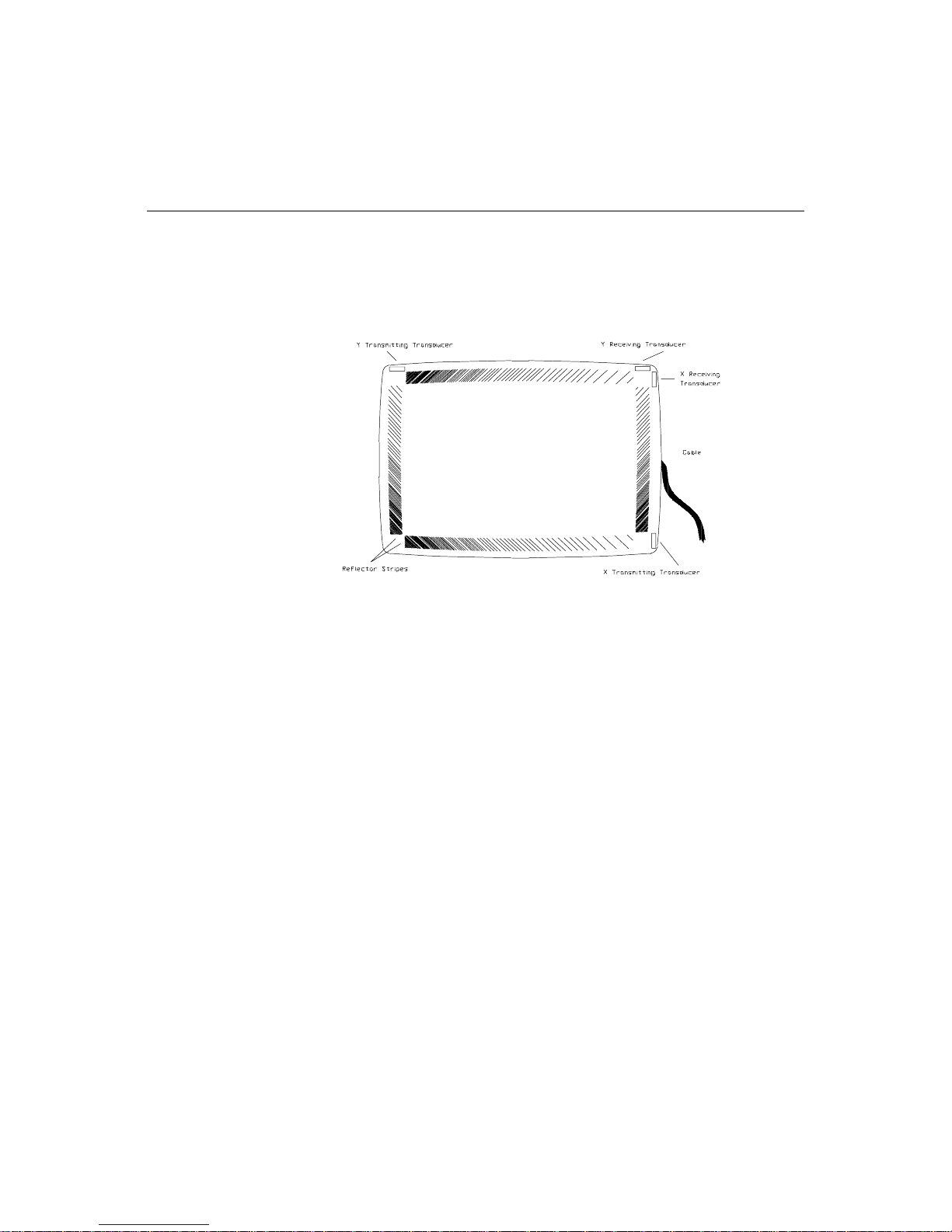
The IntelliTouch Touch screen
The IntelliTouc h surface wave technology touchscreen consists of a glass panel
molded to the shape of a display's face. Each axis of the touchscreen panel has a
transmitting a nd receiving piezoel ectr ic transducer, and sets of reflector stripes.
See Figure 2.3 on page 10 for details on the construct ion of an IntelliTouch
touchscreen.
Figure 1.1
Surface wave energy is generated by the transmitting transducers mounted in
the corners of the touchscr een. A set of reflector stripes refle cts these waves
across the activ e area of the glas s and to the receiv i ng tran s du cer whi ch
reconverts the surf ace waves into an electrical signal.
When a finger or other energy-absorbing object touches the touchscre en a
portion of the wave is absorbed. The res ulting change in the received signal is
analyzed by the controller and a digitized X and Y coordinate is determined. A
Z-axis level is determined by measuring the amount of signal attenuation at the
touch location. The X, Y, and Z coordinates are determined and the controller
transmits them to the computer.
IntelliTouch Touchscreen
1-2 IntelliTouch/SecureTouch Guide
Page 15
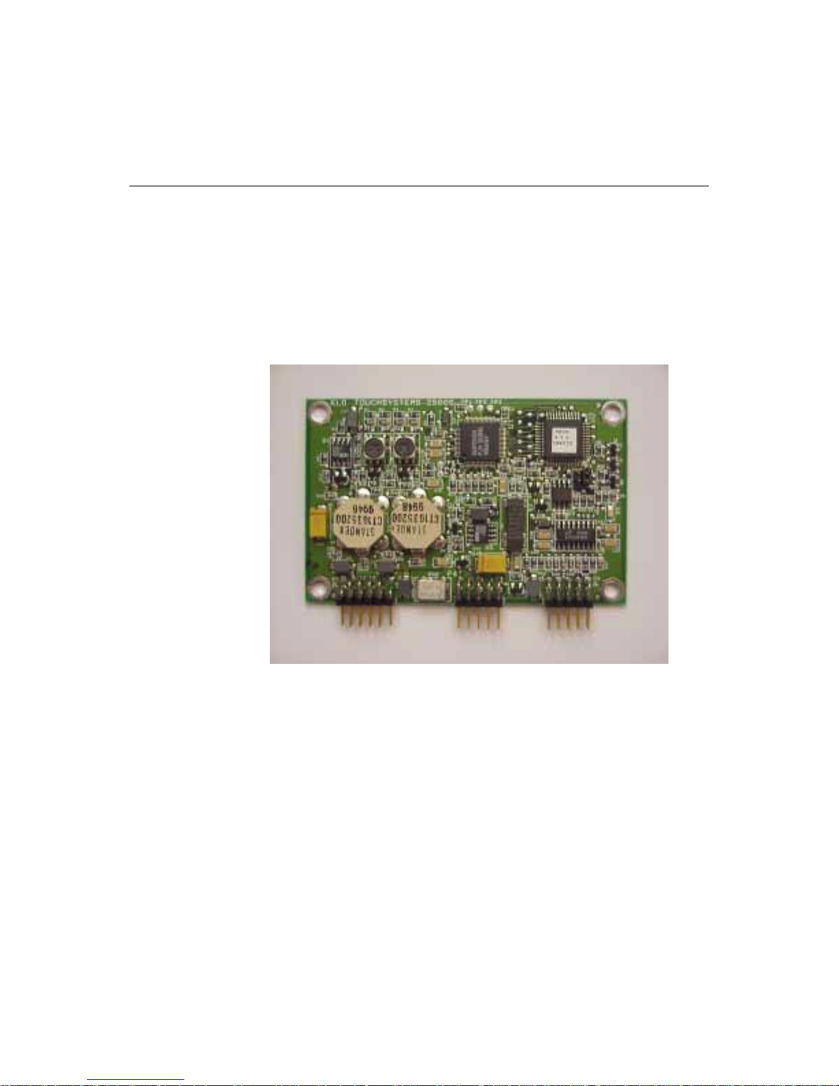
The IntelliTouch C ontro ller
The IntelliTouch controller provides the drive signal for the touchscreen,
converts the recei ved analog signals into digital touch coordinates, and sends
these coordinates to the computer.
The controller detec ts touc hes by comparing received signals to a reference
waveform acquired when the touchscreen is in an untouched condition. The
IntelliTouch controller detects dirt, dust particles, scratches and other
contaminants on the scre en and “learns around” them. It incorporates those
signals into the reference waveform to ignore the contaminants. If the
contamination is removed, the controller relearns the refere nce signal.
Figure 1.2
Because of the stabili ty of the Int elliTouch system, video realignment is not
necessary unless the position of the video image changes.
Resolution of the Intel liTouch system is defined by the controller and is
typically 4096 x 4096, with the controller transmitting at a rate of 48
coordinates per second during a touch.
The controller performs advanced internal diagnostics as well as touchscreen
diagnostics. The diagnostic results are obtain able through software as well as a
diagnostic LED. USB and serial controllers are available.
IntelliTouch controller
1-3
Page 16

Driver Software
Elo driver software pro vides a consistent software interface among all Elo
touchscreens and contr ollers.
The driver software scales the absolute coordinates received from the
touchscreen controller into translated screen coordina tes, using the calibration
points obtained with the video alignment program included with the driver
software. The driver also performs other operations as directed by the
application.
Elo provides driver pro grams for the DOS, Windows 3.1, Windows CE,
Windows 95/98, Windows NT, Windows 2000, OS/2, and Macintosh operating
systems. Additional drivers a re also available. Additional operating systems are
supported through outside sources. Refer to the Elo web site,
www.elotouch.com, for details.
If you cannot use an avai la ble driver, Elo can supply all the touchscreen related
information you will need to write your own driver for any type of system,
including UNIX workstations, real-time systems, and embedded systems. For
the 2500S contr oller, the SmartSe t™ Touchscreen Controlle r Family Technical
Reference Manual which is available on the Elo website, provide information
on this process. Machine-independent source code is included on a companion
disk and Web site, www.elotouch.com.
Agency Approvals
Elo IntelliTouch touc hscreens and controllers are “CNR/USR” UL Recogni zed
Components for USA and C anada, Category NWGQ2, I nformation Technol ogy
Equipment Including Business Equipment.
Elo IntelliTouch touc hscreens and controllers are TUV Bauart certified as
components.
Elo IntelliTouch touchscreens and controllers have been tested for compliance
with FCC Part 15 Class B limits.
1. Depending on the application, it may be necessary to pay special attention to system grounding and
shieldin g, an d it may be ne cessary to apply ferrit e suppressor beads.
1-4 IntelliTouch/SecureTouch Guide
1
Page 17
This chapter outl ines the procedures for installing touchscreen componen ts that
will convert your monitor into a touchmonitor. Details are given on mounting
the touchscreen, controller, and connecting cabl es.
Safe ty Inform ation
C HAPTER
2
C
HAPTER
2
C
OMPONENT INSTALLATION
W ARN ING
The touchscreen installation procedure outlined in this chapter may require exposure to
high-voltage components and handl ing of the CRT. This procedure can be dangerous
and an accident is potentially lethal . Therefore, the procedure should only be perfo rmed
by a qualif ied person. Read this entire chapter before attempting a touchscreen
installation.
Follow the procedure caref ully, work with the pow er off and the unit unplugged, observe
all warnings, and wear protective clothing. Elo is not liable for damage or injury resu lt ing
from the users act ions.
Consider purchasi ng a touch monitor from Elo if you do not have previous
experience working with touc hscreens and disassembling displays. Elo also
offers touchscreen installation services in quantity for a variety of displays or
can recommend third-party intergators in your area.
Work Area
Before proceeding with the installation, prepare a padded work surface. A
plastic waste baske t is recommended for supporting the CRT during part of the
installation.
2-5
Page 18

Protective Clothing
Wear safety glasses, gloves, a rubber apron, and heavy protective clothing for
any portion of this proced ure that involves handling or working near the CRT.
Getting Started
There are two types of display technologies, CRT displays and LCD displays.
IntelliTouch tou chscre ens are availabl e for most displ ays, howe ver ea ch display
may pose unique installat ion issues. If, afte r reading these instructio ns, you need
further assist ance please contact E lo Ap plicat i on Engi n eerin g for mo re
information.
These instructions assume you have purchased an Elo Touchscreen Kit and
Touchscreen Installation Kit. Only a minimum of equipment and materials is
required beyond what is provide d in the kits. Before proceeding with the
component inte gration design conside rations, please revie w the section on page
6, De sign Considerations for CRTs and LCDs, in order to optimize your
touchmonitor performance.
Design Co nsiderat ions for CR Ts and LCD s
Before designing an LCD or a CRT touchmonitor you should consider the
followin g criter ia (all detai led late r in t he chapter.):
• Ensure the touchscree n active area and overall glass dimensions are
compatible with the displa y viewing area. For CRT displays, additionally
check to make sure the radius of curva ture (ROC) of the display matches the
radius of curvature of the touchscreen.
• Ensure that adequate powe r is avai lable for the controller.
• Ensure the bezel does not contact the transducers located on the edge of the
touchscreen.
• Ensure the bezel lands in the sealing area of the touchscreen. See Figure 2.1
on page 7.
• Ensure there is a suitable location to mount the IntelliTouch controller.
• A seal should be use d between the display bezel and the touchscre en. Ensure
that the display and its mounting can withstand the force from the
compressed seal. See page 30.
• Ensure the CRT tube can be moved back so there is space for the
touchscreen.
2-6 IntelliTouch/SecureTouch Guide
Page 19
• To prevent touchscreen breakage, there should be a compliant gasket
between the back of the tou c hsc reen an d the fro nt of the display to allow for
variation in the sur face s when asse mbling. A gap is also r equire d betwe en the
touchscreen a nd the face of an LCD display to prevent damage to the displ ay.
• Unlike CRT's, plasma, EL, and backlit LCD displays may be a significant
source of heat. The situation may be more significant if the unit is sealed.
Any installation must avoid heat rise that exceeds the touchscreen
specification.
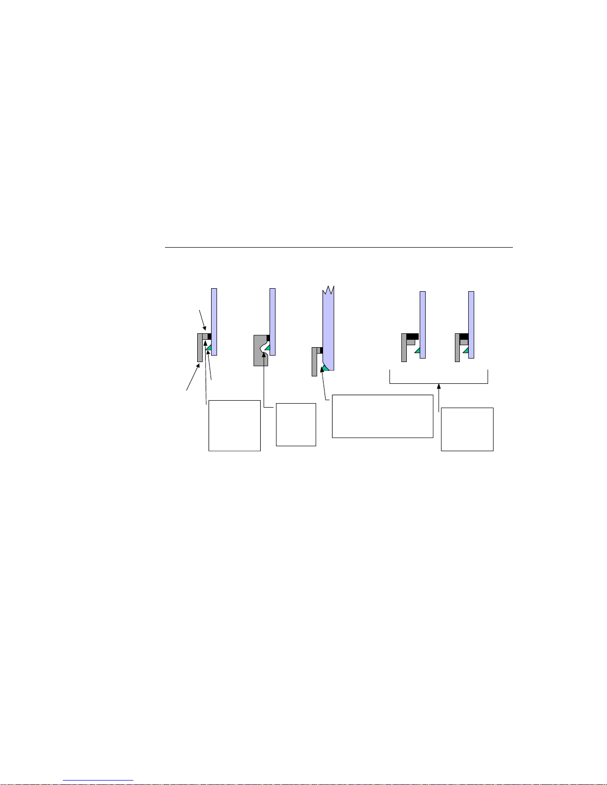
Bezel Design
The following graphic displays som e bezel ideas in or der to help you mount the
bezel to the touch scree n .
Hard
Lip
Bezel
Figure 2.1
Transducer
Wedge
With thin bezel,
add a 2-3mm
hard lip to
protect
transducer
wedge.
Bezel design
With thick
bezel, mill
out hole for
transducer
wedge.
Before
Compression
Even on a beveled touchscreen,
the transducer sticks up 1mm
above the glass. Add a spacer
to ensure clearan ce . Seal
thickness will not suffice.
After
Compression
Another idea:
Add a hard lip
behind the seal
to control
compression.
2-7
Page 20
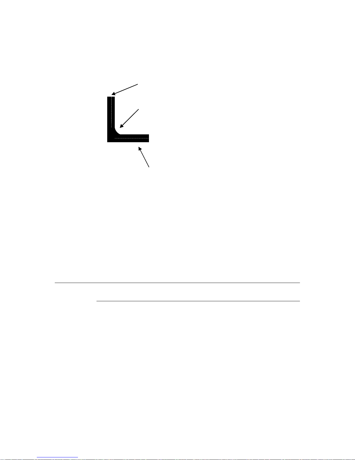
Bevel edge for nice appearance
Round corners for nice appearance and easy cleaning
On bezel and cabinet, choose paint finish and/or
surface texture so fingerprints do not show
Figure 2.2
It may be necessary to cut r ibs and struts inside the bez el. Cutting these ribs and
struts does not usually caus e difficulties, although the stif fness of the bezel may
be reduced slightly . Try not to c ut into the posts for the CRT attachment sc rews.
Bezel and tube combinations tha t require this cut are rare.
Generally, a total cleara nce between the edge of the touchscre en and any ribs or
struts of at least 0.25-inch (6 mm) in both axes is necessary. This prevents the
interferen ce fit problem and allows for variation in touchscreen mounting
position.
CR T Integr ation
Safety Infor mati on
Before proceeding with the installation, prepare a padded work surface. A
plastic waste baske t is recommended for supporting the CRT during part of the
installat ion. Wear safety glasses, gloves, a rubber apron, and heavy protective
clothing for any portion of this procedure that involves handling or working
near the CRT.
Note:
This document describes the basic tasks common to the majority of CRT monitor
integrations. These in structions assume an audience of trained integration personn el.
Bezel ed g e
2-8 IntelliTouch/SecureTouch Guide
Page 21

Definiti on o f Terms:
MONITOR: The term "monitor" refers only to t he monitor, tele vision, or other
display that is to be integra ted.
BEZEL: The term “bezel” refers to a specific part of the molded plastic cabinet
of the monitor. The bezel is the part that covers the front of the CRT and
separates it from the rear case.
CASE: The term "case" refers to a specific part of the molded plastic cabinet of
the monitor. Th e cas e is the part tha t sep ara te s from the fron t bezel . Th e cas e
normally covers the top, sides, back and bottom of the monitor assembly.
LCD: Liquid Crystal Display. Also referred to as the Panel.
CONTROLLER: The electronic device that converts touch data into USB
information. For purposes of this document the controller referred to is the
2500U, which is the Elo internal IntelliTouch USB controller 2500U. Part
number 714259-000.
Suggested Tools
Along with a copy of the monitor manufactur er’s manual, the following list of
tools may be needed to install the touchscreen. Some of the tools are optional,
but useful.
• Long (at least 9 inches, 230 mm) flat blade screwdriver with insula ted handle
• Clip lead or heavy-gauge wire
• #2 Phillips screwdriver
• Scissors
• X-Acto knife (No. 11 blade) or hand milling tool
• DB9 hole punch (not needed for 2500U)
•Cable ties
• Household glass cleane r
• Paper towels
• Small containers or plastic bags to hold loose parts
The Elo Touchscreen Insta lla tion Kit is also recommended, and includes
commonly used materials neede d for touc hscreen installation. This kit is useful
for identifyi ng preferred materials for your own procurement and may also be
cost-effective and convenient when purchased for a limited number of
installations. (See “Elo Part Numbers” on page 79.)
2-9
Page 22
Summ ar y of In st all ati on Ste p s
The CRT installation process consists of the following steps:
1 Incoming inspection
2 Disassembling the monitor
3 Attaching the touchscreen to the CRT
4 Installing the controller
5 Routing the touchscreen cables
6 Reassembling the monitor
7 Sealing the monitor
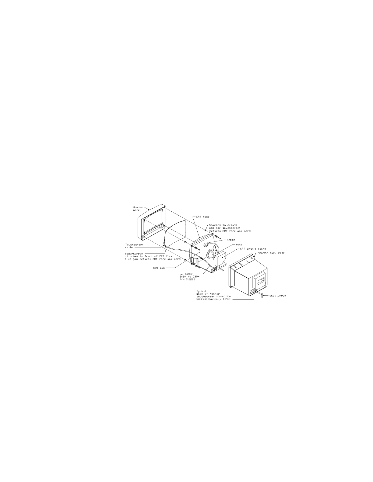
Specific compati bility may not be confirmed until well into the installation.
IntelliTouch touc hscreens can be installed on most types of CRT displays.
Figure 2.3 shows a typical installation.
1
Figure 2.3
Most displays require complete disassembly, including remova l of the CRT, to
install a touchscr een. Dis ass embling the displa y ca n be a da nger ous proce dure if
done improperly. Any damage to the displa y or the touchscreen as a result of
improper installation is the installer’s responsibility. Without prior approval of
the display manufacturer, you will probably void the display’s warranty by
disassembling it. Also, it will be necessary to recertify the display and
touchscreen syst em for regul ato ry agen cies suc h as FC C, CE and U L /CSA if
those certific ations were originally present and need to be maintained for your
intended application.
1. To complete the first integration may take several hours.
2-10 IntelliTouch/SecureTouch Guide
Typical Int elliTouch Touchscr een Installation
Page 23

Incoming Inspection
Unpacking the Touchscreen
Handle the touchscreen with care. Note the transducers in the corners are
especially fragile. Note the location of the transducers and wiring. If any of
these are accidentally broken during handling or installa tion, or if a wire is
pulled loose, the touchscreen will not operate. Avoid excessive handling and
stress on the touchs creen cable . Wear gloves to avo id getting finge rpr ints on the
touchscreen . The touc hscreens are pre-cl ean e d by Elo .
Testing the Monitor
The CRT display must be in good working order before beginning the
installation of the touchscreen. Inspect the monitor for cosmetic flaws or
damage. With a new display, it is suggested that you t est the display by running
it overnight. Check for acce ptable color, linearity, br ightness, contrast,
distortion, and other QC tests.
Disassembling the Monitor
Disassemble the monito r on a large, well -lit work surface. Leave space to set
aside major display compon ents. Group screws and other hardware in small
containers or in specif ic areas on the work surface as you remove them, in
relation to the part of the display where you are working.
Most display manufactur ers connect the major components with detachable
cables that have label ed and keyed con nectors; these cables are of lengths that
will usually connect to only one place. Also, screws are identifiable by type and
size, and usually will not f it in the wrong pla ce. The most dif ficult pr obl em with
missing or wrong hardware or connec tions will be with ground cables that
attach to obscure ground points on the metal chassis. When in doubt, make
notes of the connection points.
2-11
Page 24
W ARN ING
Remove the Back Case
Figure 2.3 on page 10 shows the typical construction of a 15-inch display.
Disassembly usually starts with removal of the back case. For assistance with
disassembly, consult your particular manufacturer's service manual. Carefully
lay the monitor on its face on the padded work surface and remove the screws
that attach the back case t o the be zel or frame.
While remov ing the bac k case, n ote the cle ara nce be t ween the insid e rea r
surface of the c ase a nd a small circuit board plugge d into a socket on the end of
the CRT. If there is not enough clearance to move the CRT and this circuit
board about.25 inch (6 mm) toward the rear of the case, you may be unable to
successfully install a touchscreen on the display and completely reinstall the
back case. Contact Elo Application Engineering, (1-800-557-1458 x6) for
possible alter natives.
After the back case is removed, the CRT is substantially exposed. Use extreme
care when working around the CRT.
Impact or forc e against the neck of the CRT, or the pins at the end where the small cir cuit
board is attached, could crack the tube, resulting in loss of vacuum or implosion of the
tube. Either result destroys the CRT. Implosion (collapse of the glass inward, caused by
the high va cuum in side th e tube), foll owed b y th e rebound of many gl ass pi eces ou tward ,
is potential ly l ethal to anyone in the i mmedi ate area . Handl e the CR T ca reful ly, keep tools
away from the CRT, and wear protective clothing including eye protection and gloves.
Discharge the CRT
W ARN ING
Dangerous voltages may be pr esent on the CRT anode. The anode m ay retain a very
dangerous v ol tage e v en af ter t he disp la y has been o ff f or da ys . Whil e most CRT m onit ors
now incorporat e bleeder circuits t o discharge the CRT, one must not assume that the
CRT is properly dischar ged. Accidental contact with the anode lead or anode button (the
small hole in the CRT glass where the anode lead i s att ached) prior to discharge may
result in a potentially lethal shock. Follow the procedure below carefully.
The anode le ad of the di splay fe eds hi gh vol tage from the f lyback t ransfor mer to
the anode button on the CRT. The anode lead is usually red in color, and the
actual connecti on to the anode button is usually covered by a large rubber
suction cup-li ke boot. In most displ ays, th e button i s locate d on the ta pered face,
or bell, of the CRT glass near the top of the display. See Figure 2.3 on page 10.
2-12 IntelliTouch/SecureTouch Guide
Page 25

W ARN ING
It may be necessary to remove some sheet metal to gain access to the anode
lead—be very careful to do this without making contact to the anode lead itself.
Carefully discharge the CRT using the following procedure:
1 Connect a clip lead or a heavy-gauge wire to the mounting ears or the spring-
tensioned ground str ap.
2 Connect the other end of the clip lead or wire to the stem of a flat blade
screwdriver that ha s an insulated handle.
3 Hold the screwdriver by the insulated handle only. Insert the blade of the
screwdriver under the rubber boot and make contact with the anode lead at
the button. A distinct “snap” may or may not be heard as it discharges,
depending on the amount of charge pres ent on the anode.
4 Disconnect the anode lead from the button by unhooking the spring wire
clips. Note the location of the anode for proper CRT orientation during
reassembly.
The CRT will re gain a charge over ti m e, even after it has been discharged. To avoid a
dangerous elect ric shock, always discharge the CR T just before handling it , and treat it
with respect thereafter.
Remove the Electronic Chassis
Continue disassembling the display until the face of the CRT is completely
exposed. The degree of disassembly required will vary from display to display.
Normally the next step will be to remove the electronics chassis from the
display. This requires removal of a small circuit board that is usually plugged
into the socket on the end of the CRT. The circuit board is often glued to the
CRT socket with a soft adhesive which must be cut away to remove the board.
Several cables must als o be unplugged from the electronics. Typically the se
cables are:
• Four wires from the yoke of the CRT, typically in a single four-pin
connector. The yoke is the copper wire and magnet assembly at the base of
the neck of the CRT. MPR II-compliant monit ors may have addit ional cables
and connectors on the yoke.
• A two-wire cable from the degaussing coil. This coil may be attached to the
CRT, or be laying out of sight between the CRT and the bezel. Some
monitors may have two separate coi ls.
• A one- or two-wire ground cable connected between the CRT circuit board
and a ground strap. This strap is a long, uninsulated, braided wire which is
spring-tensioned to maintain contact with the bell of the CRT.
• Various cables connected to the power switch, pilot light, front panel
controls, etc.
2-13
Page 26

• Various cables connected to the power switch, pilot light, front panel
controls, etc.
Other cables may have to be unplugged from the electronic chassis. The need
for this may not be apparent until the chassis is removed, as instructed below.
Another prelimina ry step in determining touchscreen/display compatibility
should be pe rformed at this point. Before r emoving the electronics chassis, note
the clearance betwe en the chassis components and the bell of the CRT. Since
the standard technique for mounting the touchscreen involves moving the CRT
back in the display chassi s, the re must be enough clearance between
components on the chassis and the CRT after allowing for about 0.25-inch
(6 mm) movement of the CRT towards the rear of the chassis. Fail ure to allow
for this clearanc e requi rement may result in mechanical damage later
(especially in shipping). It may also cause electrical damage from shorts
between “live” components on the chassis, such as heat sinks or uninsulated
component leads, and the bell of the CRT which is usually painted with a
conductive coating tha t is grounded to the chassis through the braided wire
ground strap. Repositioning or substituting low profile components may be an
option. Contact Elo Technical Support, (1-800-557-1458 x6), for assistance.
After disconnect ing any necessary cables remove the screws that atta ch the
electronics ch assis to the bezel. Note the bezel is essentially where all parts of
the mechanical assembl y are atta ched, unless you have a rare unit that has an
internal frame . A s you pu ll the chas s is awa y from the b eze l, mak e sure tha t
cables and circuit boa rds do not hit the neck of the CRT and that nothing
becomes caught on the adjustment r ings or other components on the neck of the
CRT. Also watch for other cables that need to be disconnected. After removal,
set the electron ics ch assis aside .
2-14 IntelliTouch/SecureTouch Guide
Page 27

Remove the CRT
Removal of the CRT is next. Prepare a soft surface to set the CRT on. Remove
the screws attachi ng the CRT to the bez el, and the n remove the CRT. Do not lift
or carry the CRT by the neck or yoke assembly. Avoid contact with the anode
button, which may still have some residual charge on it, (you may wish to
discharge it again at this point). Set the CRT on the prepared surface.
Several other preliminary compatibility requirements should now be assessed:
• Position the CRT so the face is accessible, providing a soft cushion for the
neck and the yoke if they must rest on the work surfa ce. Alte rnative ly, set th e
CRT face-up in an office-type plastic was te basket, making su re that the tube
is not resting on the neck (The small thin part of the CRT is the neck). Place
the touchscree n on the face of the tube, an d ch eck to s ee tha t the face o f the
CRT and touchs creen are about the s ame size, and tha t the radi us of cur vatur e
(ROC) of each surface matches well. I f both of these conditions are not met,
you may not have the prope r touchscreen f or the displa y. Most color displays
have standard size CRT's with standard ROC's, and Elo has touchscreens for
most of them.
• Next, determine if the touchscreen will fit in the bezel without modificati ons
to the bezel. Modifications, if necessary, should be done without
compromising the mechanical integrity of the display.
• Lay the touchscreen face-down in the bezel, being careful not to damage the
transducers. Leave the degaussing coil in place, if present. The degaussing
coil is a hoop, often located between the CRT and bezel, approximately
0.25-inch (6 mm) thick, with a two-wire cable and connector. The coil was
probably unplugged from the power supply earlier.
If the touchscree n will not fit flush again st the lip of the bezel, do not force it .
An interference fit be tween the edge of an IntelliTouch touc hscreen and some
of the plastic ribs f ound in displa y bezels c an pinch and break the small wires
which carry the signals al ong the edges of the touchscreen or even result in
fracture of the glass after reassembly.
It may be necessary to cut these ribs and struts inside the bezel. Cutting these
ribs and struts does not usually cause difficult ies although the st iffness of the
bezel may be reduced slightly. Try not to cut into the posts for the CRT
attachment screws. Bezel and tube combinations that require this cut are rare.
Generally, a total cleara nce between the e dge of the touchscr een and any ribs
or struts of at least 0.25-inch (6 mm) in both axe s is necessary. This prevents
the interferenc e fit problem discussed above and allows for variat ion in
touchscreen mounting position.
2-15
Page 28

The potential inte rference between the degaussing coil and the touchsc reen
must also be evalua ted. The coil will usually fit between t he touchscreen and
the inside surface of the bezel, as there is typically a natural cavity for it. If
there is not enough space for the coil, you may have to provide additional
setback for the CRT. It may also be possible to reloc ate the coil to the bell
side of the CRT. Normally, this does not significantly reduce the coil’s
effectiveness. However, you must determine this by inspecting the display
for color proble ms aft er reas s embl y .
• Check for adequate clearance of the transducers and the cable from the bezel
structure. If the position of the cable causes difficulty, the touchscreen may
be rotated 180° (only if the touchscreen is sealed and using Elo drivers).The
preferred or ientation of the IntelliTouch touchscreen is with the cable exiting
from the right side, when viewed from the fr ont of the display. Rotation will
cause an inversion of the outp ut coordinates, which will be compensated for
automatically by Elo dri ver software, but perhaps not by other driver s. ( Flat
touchscreens should ha ve the reflector stripes on the side facing the user.)
V erify Touchscreen Fit
1 Check to ensure touchscreen dimensions match CRT display. Pla ce the
touchscreen on the face of the tube to see that the face of the CRT and
touchscreen are about the same size , a nd that the radius of curvature (ROC)
of each surface matches well. I f both of these conditions are not met, you
may not have the proper touchscreen for the display. Most color displays
have standard size CRT's with standard ROC's, and Elo has touchscreens for
most of them.
2 Determine if the touchscreen will fit in the bezel wit hout modific ations to th e
bezel. The bezel should not touch the transducers and should land in the
sealing area, not on the reflector strips.
2
Modifications, if necessary, should
be done without compromising the mechanical integrity of the display. Also
see Bezel Design section for r ecommen dations.
Note:
2. Clearance around the transducers should be 1-2 mm clearance above transducers (to prevent
dampening vibrat ion, electrical short or breakage), and 3-5 mm around transdu cers. Allow for
manufacturing variances of touch screen and integration. If the position of the cable causes difficulty,
the touchscreen may be rotated 180°. The preferred orientation of the IntelliTouch touchscreen is with
the cable exiting from the ri ght side, when view ed from the front of the display. Rotation will caus e an
inversion of the output coordinat es, which will be compensated for autom atically by Elo driver
software, but perhaps not by other drivers. (Flat touchscreens shoul d have the reflector stripes on the
side facing the use r.)
2-16 IntelliTouch/SecureTouch Guide
If the touchscreen will not fit flush agai nst the lip of the bezel, do not force it. An
interference fit between the edge of an IntelliTouch touchscreen and some of the plastic
ribs found in displ ay bezels can pi nch and break the small wires which carry the signals
along the edges of t he touchscreen or even result in fracture of the glass after
reassembly.
Page 29

3 It may be necessary to cut ribs and struts inside the bezel. Cutting these ribs
and struts does not usuall y cause difficulties, althoug h the stiffness of the
bezel may be reduced slightly. Try not to cut into the posts for the CRT
attachment screws. Bezel and tube combinations that require this cut are rare.
Generally, a total cleara nce between the e dge of the touchscr een and any ribs
or struts of at least 0.25-inch (6 mm) in both axe s is necessary. This prevents
the interference fit problem discussed above, and allows for variation in
touchscreen mounting position.
4 The potential interference between the degaussing coil and the touchscreen
must also be evalua ted. The coil will usually fit between t he touchscreen and
the inside surface of the bezel, as there is typically a natural cavity for it. If
there is not enough space for the coil, you may have to provide additional
setback for the CRT. It may also be possible to reloc ate the coil to the bell
side of the CRT. Normally, this does not significantly reduce the coil’s
effectiveness. However, you must determine this by inspecting the display
for color proble ms aft er reas s embl y .
5 Check for adequate clearance of the transducers and the cable from the bezel
structure. If the position of the cable causes difficulty, the touchscreen may
be rotated 180° (only if the touchscreen is sealed and using Elo drivers).
6 The preferred orientation of the IntelliTouch touchscreen is with the cable
exiting from the right side, when viewed from the front of the monitor.
Rotation will cause an inver sion of the output coordinates, which will be
compensated for automatically by Elo driver software, but perhaps not by
other drivers. (Flat touchscreens should have the reflector strips on the side
facing the user.)
2-17
Page 30

Attaching the T ouchscreen
Once you have verified all dimensions and checked that the bezel has plenty of
clearance around the transducers and lands inside the sealing area, you are ready
to install the touchsc reen.
1 Check room for cable routing:
• Route away from noise sourc es (flyback transfor mer, power supply, yoke ,
high voltage lead, etc.)
• Cable can be on either side.
• Avoid pinch points.
• Make up excess cable with tie wraps.
2 Ensure the display and touchscreen and are clean before inst allation.
• Use black background to ensure fingerprints and smudges are not visible.
• Compressed air is best to remove dust.
3 Use double-sided high tack adhesive tape
touchscreen to the display.
• 3 mm thi ck fo r cu rved
• 2 mm thick for flats > 15"
• 1 mm thi ck fo r fla ts <= 1 5"
3
on all four sides to attach the
• Acts as dust seal as well as an adhesive. (Make a flat “T” in corners for
dust seal.)
• Or substitute foam tape on two sides
• Or use metal frame on flats, but still use foam tape for dust seal.
3.Refer to “Elo Part Numbers” on pag e C-79 to ensure you are using the prop er
adhesive
2-18 IntelliTouch/SecureTouch Guide
Page 31

Use two layers of the double-si ded adhesive tape to achieve a total thickness
of 1/16-inch ( 2 mm). Whil e specific touchsc reen and C RT combinations may
allow the use of thi nner materia ls, 1/16- inch (2 mm) is general ly necessar y to
allow for variat ions in ROC between the two gla ss surfaces. Review the fit
between the touchscreen and the CRT before appl ying the tape. If one pair of
opposite edges has a closer fit than the other, put the adhesive tape on the
edges of the touchscreen with the better fit. See Figure 2.4 on page 19 for
typical placem en t. Y ou wan t the seal in g tap e on the rear o f the touc hscreen
so it can’t be seen in t he viewable ar ea once r eassemble d. If the re is a good fit
on all four edges, you may want to use double- sided a dhesive tape on al l four
edges. When doing this, move the adhesive tape in slightly on one pair of
edges and add foam sealing tape outside these two edges. The thicker foam
tape will keep the adhesive tape away from the CRT until you are ready to
adhere the touchscr een to the display.
Figure 2.4
Proper placement of adhesive tape to the touchscreen.
In general, the adhesive tape should be set back slightly from the edge of the
active area of the touchscreen. The adhesive tape should be attached to the
glass. When the display is reassembled, the mounting tape should not be
visible. Do not remove the liner from the exposed side of the adhesive tape
yet.
Cut and place the foam sealing tape on the back of the touchscreen to form a
dust seal as shown in Figure on page 31. This seal is particularly important
because the CRT is a good electrostatic preci pitator and will attract dust. The
adhesive tape and foam sealing tape should form a complete seal around the
touchscreen. Do not leave any gaps. The sealing tape should not be visible
when the display is reassembl ed.
Practice aligning the touchscreen on the CRT without removing the adhesive
tape liner. The installation can tolerate some horizontal and vertical shift.
However, rotational skew between the touchscreen and display axes canno t
be easily compensate d for in the video alig nment, and will also interfe re with
proper mounting of the tube in the bezel.
2-19
Page 32

When you have a good feel for the placement of the touchscreen, clean the
back side of the touchscr een and the face of the CRT again. Avoid all cont act
between the cleaning solution and the mounting materials as the cleaner may
cause the mounting materials to eventually release from the glass. Remove
all lint with a brush or compressed a ir. Remove the liner from the adhesive
tape and align the touchscr een on the display. The thicker foam tape will
keep the adhesive tape away from the CRT until you are ready to adher e the
touchscreen to the display. Now press the touchscreen firmly against the
CRT.
If you must remove the touchscreen from the CRT, cut the adhesive tape
away with a sharp thin blade, such as an X-Acto knife. The touchscreen glass
will probably break if you try to pull it off by a corner or an edge. Shave the
old adhesive tape from the touchscreen and CRT with the knife. Adhesive
residues c an be r emoved wi th d enatured a lcohol , which wil l l eave st reaks and
fingerprint smears. Use glass cleaner for the final cleaning pr ior to
reapplication of new tape.
4 Place touchscreen on CRT straight and centered.
5 Peel off 3 cm of tape backer in two opposite corners. Fold to make tabs.
6 Pull back on tab to remove tape backer from under touchscreen while
pres s in g on tou chsc re en.
7 Ensure there is nothing, such as tape, touching the reflector strips or
transducers.
Spac in g th e CRT fr om the B ezel
The last part of the touchscreen mounting procedure is to determine the
appropriate spacing of the CRT from the bezel, (with the touchs creen attached),
and to reinstall the CRT with the requi red spacers in place (refer to Figure 2.8
on page 31). Do not clamp the touchscreen between the bezel and the CRT
without proper spacers as breakage will almost certainly occur. The nominal
thickness of the touchsc reen and the two layers of adhesive tape is 3/16-inch
(5 mm). If the touchscreen is to be in contact with the bezel, 3/16-inch (5 mm)
nominal spacers would be requir ed.
Because the original CRT face-t o-bezel mount is often an interference fit, with
the bezel shape alter ed slight ly to draw it up ti ghtly a gains t the CRT, you shoul d
start with a 1/16-inch (2 mm) thicker spacer than the nominal dimension above.
Two thicknesses of spacers, plus additional washers to use as shims, are
available in the Touchscreen Installation Kit. (See “Elo Part Numbers” on
page C-79 for Touchscreen Ins tal lation Kit).
2-20 IntelliTouch/SecureTouch Guide
Page 33

During the spacer selection process, you may have to install the CRT with the
touchscreen attached in the bezel several times. To prevent the CRT from
dislodging the space rs, temporarily insert plastic tie wraps or toothpicks as
guides in the mounting post holes. After selecting the correct spacers, discard
the guides and fix the spacers more securely in place with the adhesive
"doughnuts" provide d in the Touchscreen Installati on Kit.
When spacers for the desired gap have been selected, install the CRT. Make
sure you have previously reinstalled the degaussing coil. Select a screw that is
long enough to compensate for the spacer thickness (provides at least three full
turns into the mounting post thr eads) but not so long as to penetrate the surface
of the bezel. Over-tightening the screws may strip or split the mounting posts.
Installing the Controller
Elo offers IntelliTouch USB or serial (RS-232) controllers which are typically
installed int ernal to the display.
Before installing an IntelliTouch controller, you need to ensure the following
design condition s:
• Ensure there is space for the controller and the cable headers.
• Note that cable routing may contribute to noise and crosstalk. Make sure
the controller is pla ced away from voltage sources.
• Ensure there is space for an inte rn al DC-to-DC converter or AC power
supply if either is requ ired.
Note:
• Verify power source and check specs for adequate power. The 2500
controllers use +5V@60 mA ±5% regulated.
• Ensure sufficie nt electromagnetic Interference (EMI) suppression. Instal ling
a touchscreen and controller will affect the EMI characteristics of the display.
Ensure sufficient heat d issipation. The IntelliTouch serial controller dissipates som e heat
(less than 1 wat t). A typical power supply, if requir ed, may dissipa te sever al watts more.
This places an addi ti onal load on the cooling system of the display. The available
locations to mount a controller and po wer supply may als o aff ect the cooling system of
the displa y. Only applicable if you are not using AC-to-DC power supply.
• Ensure controller can be mounted securely to metal bracket and grounded.
• Ground at least one mounting hole, but for best EMI characteristics,
ground all four mounting holes.
2-21
Page 34

Internal Serial Controller (2500S)
The mounting holes of the IntelliTouch serial controllers are sized for 0.156inch (4mm) snap-in standoff s. All IntelliTouch touchscree ns have a cable
termination that mates directly with the male header (P3) on the controller. See
Appendix B for specific mounting dim ensions and connections.
Figure 2.5
Touchscree n Cabl ing S ystem for Internal Serial Controller
Follow these steps to inst all an IntelliTouch serial controller:
1 Evaluate the monitor for proper posit ioning of the cont rol ler. Make sure th ere
is sufficient space for cable headers .
2 Evaluate the back case of the monitor to determine the best position for the
DB9 female connector. A hole for this connector may be furnished in a
variety of ways: a) mounting the connector to a chassis member that is
exposed to the display exte rior, b) mounting the connector to a chassis
member with a hole in the exterior of the case to provide access to the
connector, and c) mounting the connector to the case.
3 Mount and ground the controller card following one of the two methods:
• Mount the controller to the metal chassis using metal screws and spacers.
It can be grounded through one of the mounting holes by using one of the
No. 6 sheet metal screws and spacers provide d in the kit (See “Elo Part
Numbers” on page C-79 for installa tion kit part number). On the 2500S,
all mounting holes are plated.
2-22 IntelliTouch/SecureTouch Guide
Page 35

• If the controller cannot be mounted to a metal chassis, use a ground wire
with a lug attached to connect one of the contro ller's plated-through
mounting holes to chassis ground.
4 Connect the power cable harness (See “Elo Part Numbers” on page 79 for
part number) to the 2x5 male connec tor (See “Elo Part Numbers” on page 79
for part number) at P4 on the controlle r. Connect the other end to a power
source. If a suitable +5 Vdc power source cannot be found inside the displa y,
use an AC-to-DC power supply. The 2500S controller power requirements
are +5 Vdc nominal. Refer to Appendix B for current requirements.
P4 Pins Signal Function
1 +Pwr Supply voltage positive
2 PwrCom Supply voltage negative (tied to pin 4)
3 N/C Not connected
4 PwrCom Supply voltage negative (tied to pin 2)
5 LED Remote External LED driver
6Key
7N/C
8 Chassis Frame ground connectio n
9 -Reset Open collec tor input: = normal operatio n; short to
PwrCom = hardware reset.
10 N/C
If you have grounded the controller to the metal chassis as recommended in
Step 3 on page 22, the chassis ground connection through the power
connector, P4 pin 8, does not need to be c onnected. Likewise, do not connect
the Reset and LED Remote lines unless you have provided the appropriate
circuits.
The microprocessor pin that drives the status LED is connected to pin 5 of
the P4 power supply connector. This signal from the microprocessor may
also be used to drive an external indicator such as another LED.
To operate an external LED, connect the LED cathode to ground and the
anode to pi n 5 of the P4 conne ctor. Nominal current through the LED will be
6 mA, so a low-operating current LED should be used. An external resistor is
not required.
2-23
Page 36

5 Connect the 2x5 female connector, on the serial output cabl e (See “Elo Part
Numbers” on page 79), to the 2x5 male connector at P2 on the controller.
Mount the DB9 female end of the cable in the position determined in step 2.
The serial cable connector shell must be grounded to satisfy safety agency
approvals, as the grounding protects the user in case a wiring fault develops
in the display. If the DB9 connector she ll is not already grounded, attach the
ground wire supplied in the kit to one of the DB9s mounting screws and the
other end to chassis ground.
6 Adhere the metal plate labeled with the legend, “Touchscr een Interface”, to
the outside of the bulkhead-mounted DB9 connector. A similar plate (See
“Elo Part Numbers” on page 79) is also available with vertical labeling.
7 Label the monitor to indicate what IntelliTouch serial controller is installe d
inside the display and include its jumper settings, if any.
2-24 IntelliTouch/SecureTouch Guide
Page 37

CAUT ION
External Serial Controller
An external serial cont roller is the best choice for many integrator s for several
reasons:
• No additional cables are requir ed to install the controller . The 30-inc h
touchscreen c able is routed thr ough the rear of the display case to a 2x6 male
connector lo cated on the r ear of the control le r. Once the contr oller is inst alle d
on the rear of the display, little or none of the touchscreen cable is visible .
• The base of the controller may be permanently attached to the rear of the
display, but is easily removed from the display if necessary.
• The serial cable is permanently connected to the controller and features an
armored, moisture-resistant sleeve where the cable enters the controller
enclosure.
• An external serial cont r oller offers the added flexibil ity of using a keyboard
tap or wall-mount power supply (See “Elo Part Numbers” on page 79) if
using an internal power sourc e is inconvenient or impractical. This featur e
places fewer constra ints on the design and location of kiosks and other
applications.
Follow these steps to inst all the IntelliTouch external serial controller:
1 Determine supply power source to the controller. The controller requires +5
Vdc regulated pow er (± 0.25 Vdc) with 100 mA typical. Average power
dissipation is 0.7 W.
Before making any attempt to power the controller from any monitor power source, you
should confi rm the inst allation with your monitor supplier. F ailure to observe this caution
may destroy the monitor or seriously impair monitor performance.
• Provided you first confir m the installation with your monitor supplier, you
may attach a dire ct pow er ca ble t o a +5 Vdc sou rc e ins i de the d ispl ay or tap
unregulated monitor power in the +9 Vdc to +30 Vdc range using the Elo
DC-to-DC converter (See “Elo Part Numbers” on page 79). Typical
converter power consumption is approximately 1 W. Remember that each
integration situation is unique; you must carefully evaluate available power
rails and consi der how drawing additional powe r fr om the display will affect
monitor performance .
If you have a suitable +5 Vdc power source, atta ch the direct power cable
harness (See “Elo Part Numbers” on page 79) to the source, red to + 5 Vdc
and black to common. You must attach the green ground cable to a suitable
chassis ground for noise immunity and safety considerations. Also ensure
that the cable is long enough to reac h the back of the monitor and the
controller.
2-25
Page 38

CAUT ION
CAUT ION
Observe polarity when connecting the power leads to the power sup ply. Reversing
polarity ma y dam age the controller.
Possible power supply sourc es included:
• A direct power cable to a +5 Vdc source inside the dis play or tap unregul ated
monitor power in the +9 Vdc to +30 Vdc range using the Elo DC-to-DC
converter (See “Elo Part Numbers” on page 79). Attach the direct power
cable (See “Elo Part Numbers” on page 79) to the source, red to + 5 Vdc and
black to common. You must attach the green ground cable to a suitable
chassis ground for noise immunity and safety considerations. Observe
polarity when connect ing the power leads to the power supply. Reversing
polarity will damage the controller.
• Typical converter power consumption is approxim ately 1 W. Remember
that each integration situation is unique; you must carefully evaluate
available power rails and consi der how dr awing additi onal powe r from the
display will affect monitor performance.
• Install a powe r supply which requires a 100-240 Vac input. Connect a power
cable harness to P4 on the controller, a 2x5 header with pins on 0.100-inch
(2.54 mm) centers. Use a ribbon cabl e with an IDC connect or or crimp-towire pin receptacles. An acceptable plug can be selected from Molex series
70450, Amp AMPMODU Mod. IV product line, or Berg mini-latch housing
with Mini-PV pins. Connect a power supply to the harness and then to AC.
• If none of the above options are practical, you must use either an optional
keyboard power ta p or wall-mount power supply to furnish +5 Vdc power
to the contr o ller.
Before using a keyboard power tap, be sure sufficient power is available for the
touchscreen controller or damage ma y occur to the computer.
Before connecting a keyboard power tap to the contr oller, be sure that po wer to the CPU
is OFF. Connecting a keyboard power tap to a powered CPU may seriously damage the
CPU or the controller and will blow the keyboard fuse.
1 Decide where to mount the controller on the rear of the display case. After
choosing a location, use masking tape to hold the template in the desired spot
and drill a 1-inch diameter hole for cabling exiting the display and drill two
holes for screws that will be mounted in the display case.
2 Rou te the tou c hsc reen cab le (an d power cable if using an int ernal ly locat ed
power source) through the 1-inch diamet er hole in the displa y case. Inse rt the
touchscreen cable into the keyed receptacle in the rear of the controlle r box.
You will hear a “click” when the cable connector is properly connected to the
controller. Pull any excess cabling back into the display case and attac h the
controller to the display case.
3 Wrap excess cabling with tie wraps as required, and pr oceed to “Routing the
Touchscreen Cables ” on page 2-29.
2-26 IntelliTouch/SecureTouch Guide
Page 39

Internal USB Controller (2500U )
The mounting holes for the 2500U USB controll er are sized for 0.156-inch
(4 mm) snap-in standoffs. All current IntelliTouch touchscreens have a cable
that mates directly with the male header (P3) on the controller. The controller
must be powered from inside the monitor .
CAUT ION
Figure 2.6
Before making any attempt to power the controller from any monitor power source, you
should confi rm the inst allation with your monitor supplier. F ailure to observe this caution
may destroy the monitor or seriously impair monitor performance.
Internal USB Controller (2500U)
Follow these steps to inst all the IntelliTouch 2500U USB controller:
1 Evaluate the monitor for proper posit ioning of the cont rol ler. Make sure th ere
is sufficient space for cable headers .
2 Evaluate the back case of the monitor to determine the best position for the
USB connector. There are two possible configurations for insta lling the USB
controller.
• Configuration 1: mount the controller card so the USB connector is flush
with the back of the mo ni tor .
• Configuration 2: mount the controller inside the controller inside the
monitor and use the Elo USB cable pack (See “Elo Part Numbers” on
page 79) to mount a USB connector.
2-27
Page 40

3 Mount and ground the controller card. The grounding scheme for the
controller shou ld typically be determined consistent with EMI suppression
requirements. This may be accomplished one of two ways:
• The controller should be mounted to the metal chassis using metal scr ews
and spacers. It can be grounded through one of the mounting holes by
using one of the No.6 sheet metal screws and space rs provided in the kit.
• If the controller cannot be mounted to a metal chassis, use a ground wire
with a lug attached to connect one of the contro ller's plated-through
mounting holes to chassis ground.
4 Connect the power cable harness to the 2x5 male connector at P4 on the
controller. Connect the other end to a power source. If a suitable +5 Vdc
power source cannot be found inside the display, use a dedicated power
supply. The 2500 U contr oller powe r r equirement s are +5 Vdc nomi nal. Re fer
to Appendix C for current requirements.
5 If you have grounded the controller to the metal chassis as prefer red, the
chassis ground connec tion through the power connector, P4 pin 8, does not
need to be connected.
6 Plug the X007X cable between the card and the bulk head mounting USB
connector.
7 Adhere the metal plate labeled with the legend, “Touchscr een Interface” to
the outside of the bulkhead-mounted USB connector. A similar plate (see
pg. 79 for part number) is also available with vertical labeling.
8 Label the monitor to indicate that an IntelliTouch 2500U USB controller is
installed insi de the display.
2-28 IntelliTouch/SecureTouch Guide
Page 41

Routing the Touchscreen Cables
The intern al cables that car ry the analog touchs creen signa ls are subject to
interferen ce from variou s source s within t he display . The routing of the se c ables
should avoid the following a reas, listed in order of importance:
• flyback transformer-CRT (anode lead)
• anode lead-CRT
• inverter secti on of the power supply-Flat Panels only (most displa y power
supplies are switching power supplies, and the main DC to AC inversion
section produces most of the noise)
• yoke-CRT
• RGB video drive section of the displa y
• video input cable
• horizontal and vertical oscillator/drive sections-CRT (large caps)
Once acceptable cabl e positioning is determined, tie the cabl e down to avoid
movement during shipment. In addition to careful cable routing, other EMI
suppression techniques may be necessary to satisfy agency approval
requirements. Use ferrite beads or other radio frequency (RF) suppression
elements, additional shielding, and different gr ounding techniques as needed.
Also, attach all excess cable/service loops as close to the chassis as practical to
reduce noise emissions.
Reassembling the Monitor
With the touchscreen mounte d, a nd the cable routing and exterior interface
determined, the display must be reassembled. Reassembly is genera lly in
reverse order of disa ssembly. Beware of potential clearanc e problems between
the bell of t he CRT an d the e lectro nics chas sis, a s sho rts in this area can pr oduce
catastrophi c failure s of the displa y. Also, if the insi de surfa ce of the back case is
paint e d with a conductive c o a t ing, watch for s horts betwe e n th e CRT c i r c u i t
board and the rear of the back case, as these can also produce disastrous results .
When the electronics chassis is reinstalled, the CRT circuit board is usually
carried along with it . It is often adv isable to have a second person assist you, to
insure that this circ uit board and various other cables do not interfere with the
yoke or neck of the CRT. Safety glasses, gloves, heavy protective clothing, and
caution are strongly adv ised for all participants.
2-29
Page 42

Reconnect all cables that were removed during the disassembly procedure.
Watch for single ground connections from the CRT mount to the chassis,
between individua l chassis members, etc., which may have lugs and screws to
connect them, or sometimes individual push-on solderless connectors. Failure
to reconnect these impor tant cables may result in improper performanc e of the
display after reasse mbly and may render the unit unsafe.
Re-glue the CRT circuit board to the connector with an electronic-grade
(non-corrosive) silicone adhesive (such as GE RTV-162). Discharge the CRT
again (see Discharging the CRT, page 12), and t hen reconnect the anode lead to
the anode button, making sure the spring hooks catch inside the hole.
If practical, test the monitor and touc hsc reen at the earliest time possible before
reassembling the display, as the reassembly of the back case can be tedious. If
mistakes have been made, correc tions are easier to make if the covers are still
off.
Next, label the monitor with information about the touchscreen installed, along
with the model and settings of any internal serial controller.
For example :
Contains -2500S Serial Controller
Settings: 9600/8/1/N SmartSet/Binary/Stream Mode
Finally, remove any agency certifications (UL/cUL, FCC, TÜV, CE, etc.) for
which you have not resubmitted.
Sealing the Mo nitor
A variety of methods may be used to seal an IntelliTouch system from dust or
splashed liquids as required by the application or an industry standard:
1 Use only closed cell polyolefin (Volara) foam available from Elo.
2 Adhere the seal to the lip of the bezel. When the bezel is compressed against
the touchscreen, the Volara material will act as a seal. Make sure the bezel
and sealing tape (Volara) do not touch the reflector strips. See Figure 2. 8 on
page 31 for proper sealing loc at ion.
Proper Sealing
Figure 2.7
2-30 IntelliTouch/SecureTouch Guide
Proper and Improper Sealing
Improper Sealing
Page 43

Proper Bezel Mounting
Improper Bezel Mounting
Figure 2.8
1
Compress the seal evenly around the bezel. If the display is to be used in a
Proper and Improper Bezel Mounting
kiosk with for ced air ventil ation, the air should be filtered a nd fans should be
positioned at the intake, creating positive pressure inside the cabinet.
Sealin g Material Se le c tio n
Elo recommends a crosslinked polyolefin closed-cell foam called Volara,
manufactured by Voltek. This material is available through Elo or can be
purchased from Voltek dire ctly (use 2A, 2E, 4A or 4E weight, black flame
retardant ma teri al ).
System E valua t ion
As the IntelliTouch sys tem gain is dynamic, and responds to a changing
environment quickly, the application of a seal to the system typically produces
no user perceivable effects. The touch should be just as sensitive after
integration a nd sealing as before. However, the designer should be aware of the
impact of the seal on system perform ance. Elo provides several software tools
downloadable from the website that can aid in this assessment. Use these tools
to establish basel ine performance prior to the application of the seal, as well as
after. If you need more assista nce, please contact Elo Applicatio n Engineering
(1-800-557-1458 x6).
2-31
Page 44

LCD Integration
This section outli nes the procedures for installing touchscreen components that
will convert your monitor into a touchmonitor. Details are given on mounting
the touchscreen, controller, and connecting cabl es.
Safety Infor mati on
W ARN ING
The touchscreen installation procedure outlined in this chapter may require exposure to
high-voltage components and handling of the LCD. This procedure can be dangerous
and an accident is potentially lethal . Therefore, the procedure should only be perfo rmed
by a qualif ied person. Read this entire chapter before attempting a touchscreen
installation.
Follow the procedure caref ully, work with the pow er off and the unit unplugged, observe
all warnings, and wear protective clothing. Elo is not liable for damage or injury resu lt ing
from the users act ions.
Consider purchasing a touchmonitor from Elo if you do not have previous
experience working with touc hscreens and disassembling displays. Elo also
offers touchscreen installation services in quantity for a variety of displays or
can recommend third-party integrators in your area.
2-32 IntelliTouch/SecureTouch Guide
Page 45

Summ ar y of In st all ati on Ste p s
This section describe s integration of an LCD. There are two types of
integration: de sktop LCD or LCD component. If integrating a touchscreen on an
LCD desktop, then bez el rede sign may be requi red. See “Design Consi deratio ns
for CRTs and LCDs” on page 2-6, for bezel design recommendations.
A typical LCD installation pr ocess consists of the following ste ps:
1 Unpacking the touchscreen
2 Disassembling the monitor
3 Determining touchscreen fit
4 Mounting the touchscreen
5 Installing the controller
6 Power
7 Reassembling the monitor
Unpacking the Touchscreen
Handle the touchscreen with care. Note the transducers in the corners are
especially fragile. Although the transducers may be recessed from the edge of
the glass, do not handle them unless inspection is necessary. Note the location
of the tra nsducers and wirin g. If any of the wires are accidentally broken during
handling or installation, or if a wire is disconnected, the touchscreen will not
operate. Avoid excessive handling and stress on the touchscreen cable. Elo
touchscreens are pre-cleaned, so avoid getting finger prints on the touchscreen
by wearing gloves.
Testing the Monitor
The display must be in good working order befo re begi nning the installation of
the touchscreen. Inspect the LCD monitor for cosmetic flaws or damage. With a
new display, it is suggested that you test the display by running it overnight.
Check for acceptable color, brightness, contrast , pic ture stability, and other QC
tests.
2-33
Page 46

Disassembling the LCD Monitor
Note:
The purpose of this document is t o aid i n the touchscreen integ ration of monitors. This
document is for reference only, and cannot be assumed to cover all LCD monitor
products in det ail. Elo TouchS ystems, Inc. cannot be hel d liable for any personal or
property damage incurred through use of this document. As al ways, when in doubt
contact the Elo Appli cations Engineering Department for assi stance
(1-800-557-1458 x6).
This document describes the basic tasks common to the vast majority of LCD
monitor integrations. These instructions assume an audience of trained
integration personnel.
Definition of Terms
• MONITOR: The term “monitor” refers only to the monitor, tele vision, or
other display that is defined in specific monitor’s integration.
• BEZEL: The term “bezel” refers to a specific part of the molded plastic
cabinet of the monitor. The bezel is the part that covers the LCD, and
separates from the rear case.
• CASE: The term “case” refers to a specific part of the molded plastic cabinet
of the monitor. The case is the part that separates from the front bezel. The
case normally covers the top, sides, back and bottom of the monitor
assembly.
• LCD: Liquid Crystal Display. Also referred to as the Panel.
• CONTROLLER: The electronic device that converts touch data into
RS-232 or USB information. For the purposes of this document, the
controllers referred to are the Elo internal IntelliTouch serial controller
2500S, and USB controller 2500U. See page 79 for part numbers.
2-34 IntelliTouch/SecureTouch Guide
Page 47

Tools and Equipment
• Phillips screw driver
• Common (flat blade) screw driver
• Diagonal side cutters
• Assortment of sockets
• Hand drill
• Assorted drill bits
•Pliers
• Glass cleane r an d suppl i es
• She et metal screws
• Hot melt glue gun, and glue sticks
•Zip ties
• Razor knife
Required Parts for Serial Connection
• IntelliTouch RS-2 32 controller, part number 351077-000
• IntelliTouch touc hscreen
• Monitor
• Double-sided adhesive tape
• Internal serial out cable. Part number 889507-000
Required Parts for USB Connection
• IntelliTouch USB controller, part number 714259-000
• IntelliTouch touc hscreen
• Monitor
• Double-sided adhesive tape
• USB cable pack. Part number 748578-000
2-35
Page 48

Optional P arts for Serial C onnect ion
• External serial o ut cabl e
• DC to DC Power converter and cables.
• Controller power cabl e.
• Closed-cell Poly olefin foam with adhesive on one side.
• Service manual for the monito r.
• Internal mounting kit f or serial controllers.
Optional Parts for USB Con nection
• DC to DC Power converter and cables.
• Closed-cell Poly olefin foam with adhesive on one side.
• Service manual for the monito r.
• Internal mounting kit f or controller.
• Controller power cabl e.
Notes on Disassembling the Monitor
Disassemble the displa y on a large, well-lit work surface. Leave space to set
aside major display compon ents. Group screws and other hardware in small
containers or in specif ic areas on the work surface as you remove them, in
relation to the part of the display where you are working. If you complete the
installat ion process in one session (which may require several hours for your
first efforts), it is unlikely that you will have trouble reassembling the display.
Most display manufactur ers connect the major components with detachable
cables that have label ed and keyed con nectors; these cables are of lengths that
will usually connect to only one place. Also, screws are identifiable by type and
size, and usually will not f it in the wrong pla ce. The most dif ficult pr obl em with
missing or wrong hardware or connec tions will be with single ground cables
that attach to obscur e ground points on the metal chassis. When in doubt, make
notes of the connection points.
2-36 IntelliTouch/SecureTouch Guide
Page 49

Remov in g th e Rear Ca se
Disassembly usually starts with removal of the back case. For assistance with
disassembly, consult your manufacturer's service manual.
To remove the re ar case:
• Carefull y lay the d ispl ay on its face o n the pa d ded work sur fac e an d remo v e
the screws that attach the rear case to the bezel or frame.
• Slowly pull the rear case upward.
• Disconnect any cabling that may be attached to the rear case
• While removing the rear case, note the clearance between the inside rear
surface of the case and any of the monitor’s circuitry. If there is not enough
clearance to move this circuitry about.25 inch (6 mm) toward the rear of the
case, you may be unable to successfully install a touchscreen on the display
and completely r einstall the back case . Contac t Elo Applic ations Enginee ring
(1-800-557-14 58 x6) for possible alternatives.
Removing the LCD
1 Continue disassembling the display until the face of the LCD is completely
exposed. The degree of disassembly required will vary from display to
display.
2 The next step will be to remove the LCD from the display’s hous ing. Several
cables may have to be unplugged from the LCD before it can be removed.
Typically these cables are:
• The input video connector. A multi-conductor cable that is attached to the
rear of the LCD panel.
• The back-lamp cables. One or two cables connected to the rear of the
panel. These cables origina te from the high voltage inverter.
• Various cables connected to the power switch, pilot light, front panel
controls, etc. Other cables may have to be unplugged from the electronics
chassis. The need for thi s m ay not be appare nt until the chassis i s r emoved,
as instructed below. As you pull the LCD out of the frame, make sure to
watch for other cables that need to be disconnected. After removal, set the
LCD face up on a padded, static free work surface.
2-37
Page 50

Determining Touchscreen Fit
1 Position the LCD so the face is accessible.
2 Next, determine if the touchscreen will fit in the bezel without modif ications
to the bezel. Modifications, if necessary, should be done without seriously
compromising the mechanic al integrity of the display. To do this:
• Lay the touchscreen face-down in the bezel, being careful not to damage
the transducer s. If the touchscreen will not fit flush against the lip of
the bezel, do not force it. An interference fit betw een t he edge of an
IntelliTouch touc hscreen and some of the plastic ribs found in displ ay
bezels can pinch and break the small wires which carry the signals along
the edges of the touchs cr een , or even resu l t in fract ure of the glas s aft er
reassembly.
It is often necessary to cut these ribs and struts inside the bezel. Cutting
does not usually cause difficulties although the stiffness of the bezel may
be reduced slightly. Try not to cut into the posts of any attachment screws.
Generally, a total clearance between the edge of the touchscreen and any
ribs or struts of at least 0.25-inch (6 mm) in both axes is necessary. This
prevents the interference fit problem discussed above and allows for
variation in touchscreen mounting position.
3 Check for adequate clearance of the transducers and the cable from the bezel
structure. The preferred orientation of the IntelliTouch touchscreen is with
the cable exiting from the right side, when viewed from the front of the
display. If the position of the cable causes difficulty, the touchscreen may be
rotated 180° on units (that incorporate a seal). Rotation will cause an
inversion of the output coordinates, which will be compensated for
automatically by Elo dri ver software, but perhaps not by other driver s. The
touchscreen must have the reflector stripes on the surface facing the user.
2-38 IntelliTouch/SecureTouch Guide
Page 51

Mounting the Touchscreen
When preparing the touchs creen for mounti ng to the LCD, major c onsi deration s
are:
• Reasonable mechanic al alignment with the display.
• Mounting materials and methods.
• A complete dust seal between the touchsc reen and the LCD.
• A mounting technique that evenly supports the touchscreen on at least two
opposite edges. Elo recommends double-sided tape on all sides of the LCD.
• Creating enough space betwe en the touchscreen and the bezel to
accommo date the touch s cr een and the tr ans duc ers . Adequ at e sp aci ng can
normally be accomplish ed by:
1 trimming or milling the inside of the bezel.
2 using spacers to move the LCD ba ck in the chassis.
3 using spacers to move the bezel away from the touchscreen. A
combination of moving t he LCD back with sp ace rs and tr imming the bez el
is the usual solut i o n.
• The seal between the touchscreen and the display bezel.
The last three consider at ions listed above should determine the nominal
thickness of the spacers to be used.
Many monitors will have sufficient space in the bezel to allow the touchscreen
face to re st against the l ip of the bezel, with the lip tou chi ng the active region of
the touchscreen. However, the transducers should not be in contact with the
bezel. Assuming double-sided tape is used to atta ch the touchscree n to the LCD
the final spacing will be determined by the type of seal to be used. See
“Sealing” on page 2-41, for an explanation of sealing methods.
Before mounting the touchs creen, clean the face of the display and the back of
the touchscreen with household glass cleaner. Be sure to remove all
fingerprint s. The space between the touchscreen and the display face must be
clean and free of any foreign objects.
Mount the touchscreen as follows:
• Layer the d ouble-side d adhesive tape to a chie ve a tot al thickness of 1/1 6-i nch
(2 mm); across the entire top, bottom, and sides on the rear of the
touchscreen. In general, the adhesive tape should be set back slig htly f rom
the edge of the active area of the touchscre en . When the d ispl ay is
reassembled, the mounting tape should not be visible. Make sure that the
double-sided adhesive tape butts in the corners to form a dust seal. Do not
remove the liner from the exposed side of the adhesive tape yet.
2-39
Page 52

Figure 2.9
Attaching double-sided adhesive tape to the touchscreen
• Practice aligning the touc hscreen on the LCD without removing the adhesive
tape liner. The installation can tolerate some horizontal and vertical shift.
However, rotational skew may interfere with proper mounting of the LCD
touchscreen in the bezel.
• When you have a good feel for the placement of the touchscreen, clean the
back side of the touchs cr een an d the face of the LCD. Avoid al l cont act
between the cleaning solution and the mounting materials as the cleaner may
cause the mounting materials to eventually release from the glass. Remove
all lint with a brush or compressed a ir. Remove the liner from the adhesive
tape and align the touchscr een on the di spla y. Now press the touchscreen
firmly against the LCD.
• Inspect your result s carefully for alignment, trapped dust or lint, and a good
seal between the touchsc reen and LCD. If there is trapped lint, you may be
able to remove it without removing the touchscreen by capturing it with a
thin wire. Poke the wire through the adhesive tape, and stick the lint to the
wire. Pull the lint back into the tape and embed it there.
• If you must remove the touchscreen f rom the LCD, cut the adhesive tape
away with a sharp thin blade, such as an X-Acto knife. The touchscreen glass
will probably break if you try to pull it off by a corner or an edge. Shave the
old adhesive tape from the touc hscreen and LCD with the knife. Adhesive
residues can be re moved with isopr opyl alc ohol, whic h will leave streaks and
fingerprint smears. Use glass cleaner for the final cleaning pr ior to
reapplication of new tape.
2-40 IntelliTouch/SecureTouch Guide
Page 53

Note:
Note:
Sealing
Sealing the Int elliTouc h to uchscreen is not r equir ed for oper ation; however, it i s
recommended to increase the resistance to dirt and moisture. Elo recommends
using closed-cell polyolefin based foam with an adhesive backing on one sid e.
Elo sells sealing foams with varying thickness to accommodate most needs.
Other foams ma y actually reduce the acoustic signal, thus resulting in detrim ental
effects.
Install the seal as follows:
• Place the bezel fa ce down on a padded surface, so that you can obta in access
to the insid e l ip .
• Cut enough of the sealing foam so that it can be installed in one continuous
run.
• Starting from the middle- top; Begin placing the sealing foam, adhesi ve side
to the bezel.
• The sealing foam should be flush with the bezel ope ning, and not dipping
inward or outward.
• The radius curves in the corners can be aided by slightly nicking the outside
of the sealing foam just before the corner.
• Butt the end of the sealing foam tightly against its beginning.
The sealing f oam m ust be pos iti oned s o that it mak es contact with t he touc hscr een wit hin
the activ e area. It is not acceptable for the sealing foam to contact the reflect or arrays
(See page 30 for details).
Spac ing th e LCD fr om the B ez el
The last part of the touchscreen mounting procedure is to determine the
appropriate spa cing of the LCD from the bezel, (with the touc hscr een attached) ,
and to reinstall the LCD with the required spacers in place. Do not clamp the
touchscreen between the bezel and the LCD without proper spacing as
breakage will al most certa inl y occur. Th e nominal t hickne ss of th e touc hscree n
and the one layer of adhesive tape is 3/16- inch (5 mm). If the touchscreen were
to be in contact with the bezel, 3/16- inch (5 mm) spacers would be required.
During the spacer selection process, you may have to install the LCD with the
touchscreen attached in the bezel several times to obtain proper fit. When
spacers for the des ired gap have bee n sel ected , insta ll the L CD. Sel ec t a screw
that is long enough to compensate for the spacer thickness (provides at least
three full turns into the mounting post threads) but not so long as to penetrate
the surface of the bezel. Over -tightening the screws may strip or split the
mounting posts.
2-41
Page 54

Installing the Controller
Internal Serial Controller (2500S)
The mounting holes of the IntelliTouch serial controllers are sized for
0.156-inch (4mm) snap-in sta ndoffs. All Inte ll iTouch touchsc reens ha ve a cable
termination that mates directly with the male header (P3) on the controller. See
Appendix B for specific mounting dim ensions and connections.
Figure 2.10
2500S Internal S erial Controller
Follow these steps to inst all an IntelliTouch serial controller:
1 Evaluate the monitor for proper posit ioning of the cont rol ler. Make sure th ere
is sufficient space for cable headers . Also cho ose a locat i on tha t allo w s the
cables to be installe d with adequa te slack, and provides for easy access
during install ation.
2 If possible, mount the controller directly to the metal chassis using No. 6
sheet metal screws and spacers provide d in the controller mounting kit. If you
must mount to a location other than the meta l chassis, or if you intend to use
adhesive base snap-in sta ndoffs, you must ground the controller through the
use of pin 8 on connector P4 of the controller.
3 Attach the touchscreen cable to connector P3 of the controller, and secure it
with a small amount of glue.
4 Take up the excess cable with zip ties and secure.
Note:
2-42 IntelliTouch/SecureTouch Guide
It is recommended t aht at least one of the control ler’s mounting holes be attached via a
screw nut combination to insure hol d.
Page 55

Internal USB Controller (2500U )
The mounting holes for the 2500U USB controll er are sized for 0.156-inch
(4 mm) snap-in standoffs. See Appendix B for specific mounting dimensions
and connections.
CAUT ION
Note:
Figure 2.11
Before making any attempt to power the controller from any monitor power source, you
should confi rm the inst allation with your monitor supplier. F ailure to observe this caution
may destroy the monitor or seriously impair monitor performance.
2500U USB controller
Follow these steps to inst all the IntelliTouch 2500U USB controller:
1 Evaluate the monitor for proper posit ioning of the cont rol ler. Make sure th ere
is sufficient space for cable headers .
2 Choose a location that allows the cables to be installed with adequate slack
and provides tor easy access during installation.
3 If possible, mount the controller directly to the metal chassis using No. 6
sheet metal screws and spacers provide d in the controller mounting kit. If you
do not use the metal chassis, or if you intend to use adhesive base snap-in
standoffs, you must ground the controller through the use of pin 8 on
connector P4 of the controlle r .
4 Attach the touchscreen cable to connector P3 of the controller and secure
with a small amount of glue.
5 Tak e up excess cable with zip tie s.
It is recommentd that at least one of the controller’s mounting holes be attached via a
screw nut combination to insure hol d.
2-43
Page 56

Power
Various methods can be used to obtain power for the internal USB controller.
This section addresse s the two most common methods:
• Parasitic ta p of 5V dc
• Parasitic tap of 7-30Vdc using a DC to DC converter.
Parasitic Tap of 5Vdc
It may be possible to find and use a 5Vdc power source directly from the
monitor’s circui try. Before attempting this you should cons ult the monitor’s
service manual, or the monitor’s manufacture.
Follow these steps to obtain 5Vdc directly from the monitor:
1 Find a suitable 5Vdc power source on t he cir cuitry of the displa y. I nsure that
the source can sustain the addit i ona l load requirements placed on it by the
controller. An accepta ble source should be able to supply an addition 100ma
with out effecting othe r systems in the monitor.
2 Solder or splice the non-terminated end of the controller power cable
(part number: 889507-000) to the tap loc ation. Be sure to observe the correct
polarity. The controller power cable (part number: 889507-000) uses the red
conductor for the (+) signal, the black conductor for the (-) signal , and the
green conductor for fr ame ground.
3 Attach the terminated end of the controller power cable
(part number: 889507-000) to connector P4 of the IntelliTouch USB
controller, and secure with a small amount of glue.
4 Take up the excess cable with zip ties and secure.
2-44 IntelliTouch/SecureTouch Guide
Page 57

Parasitic Tap of 7-30Vdc (DC to DC converter)
If you cannot find a readily availa ble 5Vdc source; it may be advisable to use a
DC to DC converter, and locate a 7-30Vdc source. Before attempting this you
should consult the monitor’s service manual, or the monitor’s manufacture.
Figure 2.12
DC to DC converter
Follow these steps to use 7-30Vdc and a DC to DC converter:
1 Evaluate the monitor for proper posit ioning of the DC to DC conve rter. Make
sure there is suffic ient space for cable headers. Also choose a location that
allows the cables to be ins tal le d wit h adequ a te slack , and pro vides fo r easy
access durin g instal lat i on.
2 Find a suitable 7-30Vdc power source on the circuitry of the display. Insure
that the source can sustain the additional load requirements placed on it by
the controller. An acceptable source should be able to supply an addition
100ma with out effecting othe r systems in the monitor.
3 Solder or splice the non-terminated end of the power cable (part number:
950519-000) to the tap location. Be sure to observe the correct polarity. The
cable (part number: 950519- 000) uses the orange conductor for the (+)
signal, and the black conductor for the (-) signal.
4 Connect the terminated end of power cable (part number: 950519-000) to
connector P603 of the DC to DC converter.
5 Connect the 2 position header of cable 429761-000 to connector P604 of the
DC to DC converter.
2-45
Page 58

Note:
• Connect the 2x5 position header of cable 429761-000 to connector P4 of the
IntelliTouch USB controller, and secure with a small amount of glue.
• Take up the excess cable with zip ties and secure.
Modifying the Case for Serial Output
To modify the case to accommodate the RS-232 output cable:
1 Evaluate the rear of the case to determine the best position for the DB-9
connector. A hole for this connector may be furnished in a variety of ways:
• Mounting the connector to an internal chassis member with a hole cut in
the rear case to expose the connector.
• Punching a DB-9 style hole in the exterior of the case, and mounting the
connector directly to the case. (Such DB-9 punches can be obtained from
industrial supply vendors).
2 Mount the DB-9 header of the RS-232 output cable (part number: 942741-
000) using one of the above techniques.
If mounting to a non-grounded locatio n, at tach a grounding cable to one of the
jackscrews and terminate to ground.
3 Connect the 2x5 header of the RS-232 output cable (part number: 942741-
000) to connector P2 of the IntelliTouch serial controller, and secure with a
small amount of glue.
4 Take up the excess cable with zip ties and secure.
5 Adhere the metal plate labeled with the legend, “Touchscr een Interface” to
the case area surrounding the DB-9 connector.
6 Label the monitor to indicate that an IntelliTouch 2500S controller has been
installed insi de the display.
Modifyin g th e Ca se f or USB Output
To modify the case to accommodate the USB output cable (included with the
USB cable pack):
1 Evaluate the rear of the case to determine the best position to punc h for the
bulkhead’s hole. This hole may be furnished in a variety of ways:
• Mounting the bulkhead to an internal chassis member with a hole cut in
the rear case to expose the connector.
• Punching a rectangular style hole in the exterior of the case, and mo unting
the bulkhead directly to the case. (Such punches can be obtained from
industrial supply vendors).
2-46 IntelliTouch/SecureTouch Guide
Page 59

Note:
2 Mount the USB bulkhead connector using one of the above techniques.
If mounting to a non-grounded locatio n, at tach a grounding cable to one of the
jackscrews and terminate to ground).
3 Connect one end of the 18" USB cable to the USB connector of the
IntelliTouch serial controller, and connect the other end to the receiving
connector of the bulkhea d.
4 Take up the excess cable with zip ties and secure.
5 Label the monitor to indicate that an IntelliTouch 2500U controller has been
installed insi de the display.
Brush Direction
Figure 2.13
Horizontal escutcheon plate
Re-assembling the Display
Re-assemble the displ ay by completing the disassembly steps in reverse order.
Take care to connect everything correctly and completely.
• Various methods can be used to obtain power for the internal RS-232
controller and USB controller. Refer to the Power section of this document,
page 44, to determine the method which is best fo r your particular situation.
2-47
Page 60

2-48 IntelliTouch/SecureTouch Guide
Page 61

C
HAPTER
2
T
If you experience operational difficulties with the touchscreen system either
during or after installation, the following sections will help you determine the
source of the problem.
The Troub leshooting P roces s
The first step in trouble shooting a touchscreen system is to determine whether
the problem is related to the display, software, or hardware:
A PPENDIX
A
ROUBLESHOOTING
G
UIDE
• Do not confuse display problems with touchscreen problems—the two are
unrelated.
• Software problems are det ermined by a basic hardware functionality test. If
the hardware transmits touch coordinates correctly, then the problem is
probably with the driver or application software.
• Hardware problems may be caused by the touchscreen, controller, cabling,
power supply, or by the integration of the touchscreen components in the
display. This appendix describes techniques for isolating the problem,
including power-on diagnostics, status LED verification, and component
swapping.
A-49
Page 62

Display P r oblems
If you are experiencing display problems (such as no video, no horizontal or
vertical synchr onization, raster non-line arities, etc.), remember that the video
function of the display an d the Elo touchsc reen installed on the display are
separate syste ms. Therefor e, problems with the display should be treated as
display pr oblems, no t t ouchsc reen probl ems Di agnostic p rocedures and p ossibl e
corrections for displ ay problems should be performed usin g the troublesho oting
procedures outline d in your display manual.
The IntelliTou ch touc hscr een is powe re d from i ts cont rolle r. Us ually t he displ ay
and touchscreen contr oller have separate power supplies and opera te
independently. Thus it is possible for the touchscreen to interact with the
computer even if the display is powered off. Internal serial controllers may be
powered by a supply that is separate from the display's power supply, but
controlled thr ough the displays power switch. In this case, even if display
problems exist, the touchscreen system will probably function if the display
power switch is on.
Software Troublesh ooting
Before beginning softwa re troubleshooting, verify that the touchscreen
hardware is working by running the COMDUMP program for serial controllers
(see page 52, Using the COMDUMP Utility). If the touchsc reen is operating,
then the problem may be with the driver software, the application software, or a
conflict with othe r hardware or software. (The problem may also be due to
incorrect touchscreen video alignment, described on page 51, Video Alignment
Problems.)
The general technique for tro ubleshooting software proble ms is to identify at
what layer of software and associated hardware the problem exists. For
example, if you have a Windows application, there are several layers of
software and drivers. The problem could be with your application, Windows,
MonitorMouse for Windows, MonitorMouse for DOS, the ELODEV driver, a
conflict with another device, or the touchscreen har dwa re. The best approach to
software troubleshooting is to remove the layers of software one by one, testing
each layer until the pro ble m is iso lat ed . Al so try remov i ng oth er hard w ar e and
software that may be conflicting with the touchscreen hardware and driver
software.
A-50 IntelliTouch/SecureTouch Guide
Page 63

For detailed troubleshooting information on MonitorMouse for Windows,
MonitorMouse for DOS, MonitorMouse for DOS, ELODEV, and TouchBack,
see the DOS and Windows Driver Guide, MonitorMouse for OS/2 Use r's Gui de,
MonitorMouse for Windows NT User's Guide, or MonitorMouse for Macintosh
User's Guide as appropriate, or visit Elo’s Web Tech site, www.elotouch.com/
support.
Video Alignment Problems
If the touchscreen is responding and the data is linear, but a touch does not
activate the appropriate zone in the application, try video alignment. Use
ELOCALIB under DOS or the Touchscreen Control Panel with all versions of
MonitorMouse. Improper video alignment may be indicated when the cursor
does not move at the same pace as a sliding finger , or when it moves in the
opposite direct ion. The cursor should always move in the same axis as your
finger.
If you have a DOS application, erase any ELOGRAPH.CAL files and complete
video alignment in the video mode used by your application. For example, you
may have a VGA monitor with your application runn ing in text mode, so
complete video alignment in text mode rather than graphics mode.
Also see Calibration Problems in the DOS and Windows Driver Guide for
additional infor mation.
Hardware T roubleshooting
Troubleshooting the touchscreen system hardware may require analysis of the
touchscreen, controller, cables, power suppl y, a nd the integration process. The
best place to start is with the controller.
Use the controller power-on diagnostics which are displayed when the Elo
driver softwar e is load ed t o chec k for sp ecifi c faul t s (see Diagnostic Codes,
page 59). If they are accessible, the diagnostic LED’s on serial and MX
controllers may identify a problem (see Diagnostic LED’s, page 58).
Also, check whether the controller is transmitting any touch data. Use the
COMDUMP program for ser ial contr oll ers. The 2310B op erates at 9600 baud, 8
data bits, 1 stop bit, and no parit y, ( see page 75 for controller jumper settings).
You may encounter one of the following symptom s:
• No touch data . When no touch data is reported, the problem may be the
touchscreen, controller, or cabling. If the controller power-on diagnostics or
diagnostic LED’s do not identify the problem, substitute individual system
components if they are ava ila ble. Refer to the remainder of this appen dix for
information on trouble shooting each system component.
A-51
Page 64

• Intermittent touch data. If the system is reporting touch data at a slow or
varying rate, the problem may be caused by a low signal strength or
excessive no ise in the syst em. Gene ration of t ouch data when the t ouch screen
is not touched is most likely caus ed by excessive system noise. See the
sections and, page and, respe ctively. Use of SAWDUMP (a DOS utility
included with most Elo driver software and available on Elo’s website,
www.elotuch.com, may help to identify these problems. Contact Elo
Application Engineering, 1-800-557-1458 ext. 6, for more information.
• Linearity. As the IntelliTouch system is inherently stable and drift-free,
apparent linearity problems are usually due to video alignment errors or
display drift. See Video Alignment Problems, page 51.
The remainder of this appendi x deals with component-level troubl esh ooting of
controllers , powe r supplies, the touchscreen, and cables.
Serial C on troller
The 2310B operates at 9600 ba ud, 8 data bit s, 1 st op bit, and no par ity. See page
75 for controller jumper settings.
The 2500S operates at 9600 baud.
Using the COMDUMP Utility
COMDUMP is a DOS utility included with most Elo driver softwa re and
available at www.elotouch.com. Use COMDUMP to verify basic controller
functionality and to determine whether or not data is reaching the serial por t.
COMDUMP can be run without a touchscreen driver load ed.
Type”COMDUMP <n>” where <n> is the number of the COM port. Detailed
instructions can be found on Elo’s Web Tech site, www.elotouch.com/support.
If you are not running under DOS, boot your PC from a DOS diskette before
running COMDUMP. If you cannot run DOS (use an ASCII terminal or a
communications program in local mode to get a similar type of analysis
provided by COMDUMP). Another option is to temporarily connect the
touchscreen to a PC with DOS and run COMDUMP.
If the hardware is functi oning pr operly, untranslated (raw) coordinates will be
returned at a constant rate only when the touchscreen is touched. If no data is
transmitted on touch, or if data is transmitted when the touchscreen is not
touched (either continuously or intermittently), you have a hardware problem.
If the LED is acce ssibl e, and i ndica tes that da ta is being tr ansmitte d, c onfir m the
communication paramet ers, then try another serial port, possibly on another
computer. Also see RS-232 Connections, page 54.
A-52 IntelliTouch/SecureTouch Guide
Page 65

2500S Contro ller Pr otocol
The ten-byte binary data format displayed in hex by COMDUMP for correct
operation with Elo driver software is as follows:
Byte De s crip tion
1 ASCI I 'U' (55h)
2 ASCII 'T' (54h)
3 Status Byte
4XLow
5 XHigh
6YLow
7 YHigh
8ZLow
9 ZHigh (defaults to 0)
10 Checksum
A-4002 Controller Protocol
If the controller is jum pered for A-4002 emulation mode, the output will be the
six-byte binary format as follows:
Byte MSB LSB
111X11X10X9X8X7X6
210X5X4X3X2X1X0
301Y11Y10Y9Y8Y7Y6
400Y5Y4Y3Y2Y1Y0
5000000000
60000Z3Z2Z1Z0
In this mode, the first four bytes in each packet will be decreasing, followed by
a zero byte, and a byte from 00 to 0F (hex). The Z value (byte 6) will be 00
when you lift your finger.
A-53
Page 66

RS-232 Connections
Review cable connect ions and swi tch se ttings. If you have use d your own cables
or adapters for connection to the serial port, check pinouts. Verify that the data
transfer rate (bau d rat e) o f the computer's seria l port is the sam e as se le cted by
switches or jumpers on the controller.
The IntelliTouch serial controllers operates at standard RS-232 levels. The
serial port connector, P2, is a 2x5 header with pins on 0.100-inch centers. It is
configured so a ribbon cabl e and commonly avai lable insulation displac ement
connectors (IDCs) may be used. Pin posi tions and signals are given below. See
page 60 for DB9 and DB25 connector pin positions.
9
7531
X
10 8 6 4 2
Figure A.1
P2 Pins DB25 DB9 Host Signal Source
1 8 1 DCD (N/C ) Controller
2 6 6 DSR Controller
3 3 2 RXD Controller
447RTS Host
5 2 3 TXD Host
6 5 8 CTS Controller
7204DTR Host
8 22 9 RI (N/C) N/C
975GND Common
10 Key
Pin positions for the serial port connect or
Table A.1
Serial port controller signals
The controller only requires a 2-wire connection, controller Transmit Data (P2
pin 3) and Signal Ground (P2 pin 9). For two-way communications, the
controller Receive Data (P2 pin 5) should also be connected to the host
Transmit Data pin.
A-54 IntelliTouch/SecureTouch Guide
Page 67

Data Set Ready (DSR) and Clear to Send (CTS) may be used by the host to
verify controller connections and operation. DSR is asserted when power is
applied to the controller and CTS is asserted when the controller's power-on
sequence is complete . Dat a Terminal Ready (DTR) and Request to Send (RTS)
can also be connected for full ha rdwar e handshaking.
Elo driver software typically requires two-way communication and all four
handshaking lines.
If accessib le, the controller's diagnostic LED can ve rify whether RS-232 dat a is
being transmitted.
Alternative ly, a breakout box will tell you if there is any activity on the data
line. It is possible that the port you are using on the host computer is meant to
work with an RS-232 DTE device. To check this, inst all a null modem cable
between the controll er and the host computer's serial port. A null modem cable
converts a DCE device into a DTE device by swapping pins 2 and 3 and the
handshaking lines.
Some serial ports require jumpers for the handshaking lines on the cable
connector at the computer end. The jumper combina tions that may be required
to make an RS-232 por t work ar e beyond the scope of this m anual. Consult your
computer manual for more information.
If a breakout box is not available, you c an measure the DC voltage at the data
output of the contro ller (pin 2 of the DB-9). It should m easure betwee n 8 and 10
Vdc when the touchscreen is not touche d, a nd drop seve ral volts (towards 0)
during a touch, depending on the data format and the baud rate.
If proper RS-232 signal voltage is not present, the controller may not have
power applied.
P ower Connections
Check for proper voltage (+5 Vdc) at the power connector P4 pin 1 (+) and pin
4 (-) on the controller (se e, page) . I f the LED is functioning (see page
Diagnostic LED’s), the power suppl y is probably okay. To access this connector
on the external seria l controller, disconnect the power, the n remove the cover.
Reconnect the power cable and turn t he unit on. There are no e xposed electrica l
connections in the controller that would be considered dangerous. Power is
applied to the controller through P4.
If no power is present, measure the voltage at the power source, either a source
from the display elect ronics, a DC-to-DC converter, or an AC power supply.
A-55
Page 68

Touchscreen and Touchscreen Cab les
If the touchscreen and its attached cable are easily accessible, the touchscreen
can be physically inspe cted for damage to the transducers and cable. Gently
peeling back the tape covering the transducer and wedge assembly will allow
you to see the back side of the transducer and the wires soldered to it (see Figure
A-1 Transducer and Wedge Assembly
Broken wires near the transduc ers should be obvious, but broken or cracked
transducers may be diff icu lt to see. Transducer breaks, regardless of the cause,
mostly occur at the edge of the solder connec tion. A break can generally be
detected by the cont roller power-on diagnost ics. See Diagnostic Codes, page. 59
Figure A.2
Note:
A-56 IntelliTouch/SecureTouch Guide
You cannot repair a broken transduce r in the field . Return any touchscr een with a brok en
transducer to Elo for repair or replacement.
Transducer and Wedge Assembly
Page 69

IC1 Cable
The IC1 cable is used insid e the disp lay to connect to a n exte rnal EC2 extens ion
cable and an external controller. The IC1 cable can be checked with an
ohmmeter. Pin #1 is identified by a white dot on the plastic body of the header.
The pinouts for the header and the cable are as follows:
Table A.2
X
2
4
6
8
10
X
12
Figure A.3
1
3
5
7
9
11
Pinouts for the IC1 Cable
2x6 Male Head er DB9 Male Function
1 Shell Overall Shield
31Y+Receive
5 2 Y-Receive
7 3 Shield
94X+Receive
11 5 X-Receive
46Y Transmit
6 7 Y Ground
8 8 X Ground
10 9 X Transmit
Pinouts for IC1 Cable and header
See page 60 for DB9 and DB25 connector pin positions.
EC2 Cable
This cable connects the back of a touch monit or to an external controller. It is a
straight through c able, and all nine pins are used. Check this cable with an
ohmmeter.
The interna l const ruct ion of the EC 2 cable is s pecif ic t o t he Inte lli Touch sys tem,
and other common computer data cables should not be substituted.
A-57
Page 70

Diagnostic LED's
Depending on where the control ler is installed, the LED's may or may not be
visible.
Inte lliTouc h Seria l Controllers
The IntelliTouch serial controllers have one green diagnostic LED. Following
power on, the controller performs a short self-test, where the LED stays lit.
After the self-test, the LED flashes once per second, indicating normal
operation. The self-test results are displayed by most Elo driver software.
During normal operat ion, t he LED also ind icates contr oller/host comm unication
is in progress. When the touchscreen is touched, the LED should light
continuously, then return to the normal flash rate. If the host does not remove
the packet from the controller, the LED will stay lit.
The LED will also stay lit without a touch if the touc hsc reen or cabling is
disconnected or not functioning.
If the LED flashes about two times per second, a warning error condition is
indicated, such as impr ope r co mm u nic at ion fro m the hos t. Su sp ect an inv ali d
command se que n ce from the host.
A-58 IntelliTouch/SecureTouch Guide
Page 71

Diagnostic Codes
The diagnostic codes may be a single byte or pair of bytes displayed in hex.
The following tables for each controller list the bit positions defined for each
byte. A 1 bit indicat es a fail ure. Diagnostic code s are computed by summing the
value for each bit position using hexadecimal arithmetic.
IntelliTouch Serial Cont r ol ler ( 2500S)
These controller s have a two-byte diagnostic code displayed in the form AABB. The AA byte is defined below. The BB byte is the same as the 4035
controller, defined above in Table A.1.
AA Bit Value (hex) Description
7 80 Touch microprocessor test incomplete
6 40 Reserved
5 20 Touch microprocessor test failed—touchscreen may not be
connected
4 10 Nonvolatile RAM checksu m test failur e
3 08 RAM read /write test failure
2 04 ROM checksum test failure
1 02 Micro p rocessor logic/register test failure
0 01 Firmw ar e /hardwar e co m p atibilit y te st fai l u re
Table A.3
The IntelliTouch Serial Controller (2500S) bit position relating to each byte.
A-59
Page 72

DB9 and DB25 Connector Pin Positions
The following figure is use ful when locating pin positions on DB9 and DB25
connectors.
Figure A.4
A-60 IntelliTouch/SecureTouch Guide
DB9 and DB25 Connector Pin Pos itions
Page 73

A PPENDIX
B
C
HAPTER
2
S
PECIFICATIONS
The following specific ations are subject to change without notice.
Many of the IntelliTouch specif ic ations are controller- dependent. Refer to the
IntelliTouch Touchscreen Products brochure or the Technical Reference
Manual for your controll er for the se additional specifications.
IntelliTouch pr oducts are covered by one or more of the following patents:
4,642,423; 4,644,100; 4,645,870; 4,700,176; 4,746,914; 4,791,416; 4,825,212;
4,859,996; 4,880,665.
B-61
Page 74

IntelliTouch Touchscree ns
Mechanical
Construct ion
Dimensions
Cable and
Connector
Positional
Accuracy
Resolution
Touch Activation
Force
Surface
Durability
Expected Life
Performance
Optical
Light
Transmission
Visual Resolution
Gloss
Electrical
Environmental
Temperature
Operating
Relative Humidity
Glass panel with transducers attached to front surfa ce of the glass. Glass panel thickness
nominall y 0.115-inc h (3 mm). Corner-mounted transducers add maximum of 0.150-inch
(4 mm). Beveled flat screens have trans ducers attached to a beveled edge of the gla ss.
The follo win g physi cal di mens ions o f t he t ou chscr een are sp ecifi ed for each m o del in th e
IntelliTo uch Touchs cr een Pr oduc ts br oc hure o r the appr opr iate Elo Sp eci fic at ion Con tr ol
Drawing. Drawings can be found on Elo’s web site, www.elotouch.com
Horizontal and Vertical physical size
Horizontal and Vertical border re gion size
Horizontal and Vertical touch active area size
Radius of curvature information
Cable exit location, length, and connector type
Cable typically exits from the right side, terminating in a 2x6 female, 0.025-inch (0.635
mm) square po st receptacle with 0.100-inch (2.54 mm) centers.
Standard deviation of error is less th an 0.080 in. (2 mm).
4096 x 4096 touch points (approximately 400 touch points per linear inch)
Typically 2 to 3 ounces (55 to 85 grams).
Surface durability i s that of glass, Mohs’ hardness rating of 7.
No known wear-out mechanism, as there ar e no layers, coa tings, or moving parts. The
IntelliTouch technology has been operational ly tested to more than 50 million touches in
one location without failure, using a stylus similar to a finger.
90% per ASTM D1003-92
Clear surface: Excellent with no noticeable degrad ation.
Anti-g la re surfac e : 6: 1 minimum.
All measure ments made using U SA F 1951 Resolution Chart, under 30X magnifica tion
with test unit located approximately 1.5-inch (38 mm) from surface of resolution chart.
Clear surface: N/A
Antiglare: 75 ± 15 gl oss units pe r ASTM D2457- 90 using a 60° gloss mete r. For flat s, 85
± 15 gloss unit s per ASTM D2457-90.
All touc h sc reen drive sig na ls are devel op ed by the inte rf a cing contro ll er. Refer to th e
Technical Reference Manual for your controller or to the Intel liTouch Touchscreen
Products brochure for these specifications.
Operating: -20°C to 50°C.
Storage: -40°C to 71°C.
40°C at 90% Rh, non-condensin g.
B-62 IntelliTouch/SecureTouch Guide
Page 75

Altitude
Chemical
Resistance
Electrostatic
Protection
Agency
Approvals
UL Compliance
Fire Retardation
FCC Compliance
Operatin g: 10,000 ft (3, 048 m).
Storage/transport: 50,000 ft (15,240 m).
The touchac tive area of the touchscreen is resistant to all chemicals that do not af fect
glass, such as:
Acetone
Toluene
Methyl ethyl ketone
Isopropy l alcohol
Methyl alcohol
Ethyl acetate
Ammonia-b ased glass cleaners
Gasoline
Kerosene
Vinegar
When tested per IEC 801-2 (150 pF and 150 Ω), the touchscreen shall withstand 20 air
discharges of 15 kV, distr ibuted randomly across t he active area of the touchscreen.
IntelliTouch touchscreens are UL-Recognized Components. UL file no. E162681
Meets the requirements of UL94HB.
Systems incorporating Elo touchscreens, controllers and cables have been approved to
FCC Class "B" compliance.
B-63
Page 76

IntelliTouch 2500U US B Cont roller
Electrical
Supply Vol tage and
Current
Interface
Operating Modes
Touch Resolution
Conversion Time
Reliability
Environmental
Temperature
Humidity
Operating Altitude
Shock and V ibration
ESD
Flammability
Physical
Characteristic s
Construction
Dimension
Connectors and Pin
Definitions
USB Output
Connector
+5 Vdc, nominal (+4.75 to +5.25 Vdc).
50 mA, typica l at +5 Vdc. Avera ge power dissipation is 0.25 W, typical.
Supply must be capable of sourcing 100 mA, minimum.
Total noise and ripple re quirement must be less than 100mV (p-p) for frequencies
below 1MHz, and less than 50mV (p-p) for frequencie s above 1MHz.
USB High Speed
Plug and play com patible
IntelliTouch SmartSet protocol.
Initial/Stream / Un touch/ Z-a xi s Ena b le Mo d es .
Approximately 4096x4096, size indep endent, 255 le vels of Z (press ure).
Approximately 10.4 ms per coordinate set.
MTBF greater than 345,000 hours per MIL-HDBK-217-F2 using the parts st ress
calculation method
for the ground benign environment with an ambient
temperatur e of 25°C
Operating: 0°C to 65°C
Storage: -25°C το 85°C
Operating: 10% to 90% RH, non-condensing.
Storage: Same.
10,000 feet.
Three axis sine wave, 50Hz to 2kHz, 1G, 2 minutes/Octave with dwell on resonance.
Per EN 6100-4-2 1995: Level 4. Contact discharge 8kV, air discharge 15kV
The printed circuit board substrat e is rated 94V0. All plastic components, such as
head er s an d conne ct or, are also r at e d 94V0.
Four-layer surface- m ount design wit h internal gr ound plane for EMI suppression.
Total Width: 2.36 inches (59.94 mm), inclu ding connectors
Total Length: 3.51 inches (89.03 mm), incl uding connector
Total height: 0.61 inches (15.44 mm)
All mounti ng holes are pla ted through-holes for chassis ground connection . Refer to
the drawings at the end of th is document.
The connector configuration permits the controller to be placed in-line between the
touchscreen and a USB hub or host attachment.
The USB connector, P2, is a USB Ser ies “B” receptacle as specif ied in sect ion 6.5 of
the USB speci fication, version 1.1. The pi ns are numbered as shown on page
Table B.1 on page 66.
B-64 IntelliTouch/SecureTouch Guide
Page 77

Touchscreen
Connector
Power Connector, P4
The touchscreen connector, P3, is a dual row by six position header with 0.025 inch
square pins spaced on 0.100 centers. P3 m ates with the Berg Mini-Latch receptacle
on the IntelliTouch® touchscreen cable. The pins are num bered as shown in
Figure B.2 on page 66. The withdrawal force exceeds 3.9 lbs.
The power connector, P4, is a 2 row by five-position header with 0.025-inch pins on
0.100 centers. The heade r is compatible w ith insulation displacement cable (IDC)
connecto rs such as Berg series 71600, ser ies 71602, ser ies 66900, and series 66902,
Molex styl e 40312, Amp se ries 746285 and series 746288 receptacles. The header is
also compatible with crimp termination, discrete wire receptacles and housings
including Berg Mini-Lat ch housings and Mini-PV receptacles, Molex series 70450
connectors, and the Amp AMPMODU Mod. IV connector family. Pin numbering
schemes for discret e w ire connectors differ between manufacturers.
Refer only to Fi gur e B.3 on page 66 for pin numbe r lo cati ons . Signa l co nnec tion s are
shown on page Table B.3 on page 67.
B-65
Page 78

21
D-
VBUS
1
2
Table B.1
4
cable-mounted
plug
Figure B.1
GND
D+
board-mounted
receptacle
43
P2, USB board-mounted header and cable-mounted plug.
USB connector pin numbers and signal names
P2 pin numb er Signal name Standard wire color
1VBUSRED
2D-WHITE
3 D+ GREEN
4 GND BLACK
shell shield drain wire
2
1
Board mounted
12
11
header
12
11
Cable applied
plug
3
2
1
Figure B.2
Pin diagram for touchs creen connector, P3, as viewed from conne ctor
mating surfaces.
9
10
Board mounted
header
Figure B.3
B-66 IntelliTouch/SecureTouch Guide
Power connector board-m ounted header and cable mounted-plug.
1
2
1
2
9
10
Cable applied
plug
Page 79

Table B.2
IntelliTouch touchscreen connector pin numbers and signal descriptions
Signal name P3 pin Signal functio n
Chassis 1 frame ground for
cable sh ie ld
none 2 connector key
Y rcv + 3
Y xmt + 4
Y rcv - 5
Y xmt - 6 analog ground
analog gnd 7 analog ground
X xmt - 8 analog ground
X rcv - 9
X xmt + 10
X rcv + 11
none 12 connec tor key
Table B.3
Power connector, P4 pins and signal descriptions
Signal name P4 pin Signal function
+Regulated Pwr 1 +5 volts DC +/- 5%
Pwr Com 2 Supply voltage common
reserv ed 3 no connect ion allowed
Pwr Com 4 Supply voltage common
n/c 5
n/c 6 key location
n/c 7
Frame groun d 8
n/c 9
reserv ed 10 no connect ion allowed
B-67
Page 80

LED Diagnostic Ch aracteristics
A green LED (D1) indicates control ler status as follows:
LED Blink Rate Function
Once per second Normal condition, untouched state
On continuo usly Touched st ate
Twice per sec ond Error detected
A second LED (D6) indicates USB status as foll ows:
LED State Function
OFF Controller is not enumerated on U SB
ON Controller is enumerated on USB, but there is no data transfer
Blinking USB data transfers between controller and host are occurring
Agency Approvals
• Elo controllers are “CNR/USR” UL Recognized Components for USA and
Canada, Category NWGQ2, Informat ion Technology Equipment Including
Business Equipment.
• Elo contro ller s are TUV Bauart certified as com pon e nts.
• Elo controllers have been tested for compliance with FCC Part 15 Class B
limits
*
.
• Depending on the appl ication, it may be necessary to pay special attention to
system grounding and shielding, and it may be necessary to apply ferrite
suppressor beads.
B-68 IntelliTouch/SecureTouch Guide
Page 81

2500U USB Controller Drawings
Figure B.4
Figure B.5
2500U USB Controller, top view
2500U USB Controller, thru-hole locations
B-69
Page 82

Figure B.6
2500U USB Controller, bottom-view
Figure B.7
Note:
B-70 IntelliTouch/SecureTouch Guide
Side view values represent typical dimensions.
2500U USB Controller, side view
Page 83

IntelliTouch 2500S Se rial Contr oller
Electrical
Supply Voltage and
Current
Interface
Baud Rate
Operati ng Mo des
Touch Resolution
Conversion Time
Relia bility
Environments
Temperature
Humidity
Operating A ltitude
Shock and Vibration
ESD
Flammability
Physical Char acte ris tics
Construction
Dimensions
+5 Vdc, nominal (+4.75 to +5.25 Vdc).
60 mA, typical at +5 Vdc. Average power dissipation is 0.3 W, typical.
Supply must be capable of sourcing 100 mA, minimum.
Total noise and ripple requirement must be less than 100 mV (p-p) for
frequencies below 1 MHz, and less than 50 mV (p-p) for frequenc ies above 1
MHz.
EIA 232E (Serial RS-232), DCE configuration. 8 Data Bits, 1 Stop Bit, No
Parity, Ful l Duplex.
Hardware handshaking: RTS/CTS
DSR is pulled HIG H (> +3V) by the 2500S w hen connected and powered. DTR
is ignored
9600 (default) and 19200
Full IntelliTouch SmartSet or E281A-4002 protocols, jumper sele ctable.
Initial/ Stream/ Untouch/ Z-axis Enabl e Modes.
4096x4096, size indepen d ent, 255 levels of Z (pressure).
Approximately 10.4 ms per coordinate report.
MTBF greater than 300,000 hours per MIL-HDBK-217-F2 (using the parts
stress calculatio n m ethod for ground benign envi ronment with an am bient
temperat ure of 25°C).
Operating:0°C to 65°C.
Storage:-25°C to 85°C.
Operating:10% to 90% RH, non-condensing.
Storage:10% to 90% RH, non-condensing.
10,000 feet.
Three ax is since w av e , 50 Hz to 2kH z , 1 G , 2 m in u tes/Oct av e wi th dw ell on
resonances.
Per EN 6100-4-2 1995: Level 4. Con tact discharge 8kV, air disc harge 15kV.
The printed c ir cuit boar d subs tr ate is ra ted 94V 0. Al l pl asti c c ompon ents, suc h a
headers and connectors, are also r ated 94V0.
Four-layer surface- m ount design wit h internal ground plane for EMI
suppression.
Total Width: 2.36 inches (59.94 mm), inclu ding connectors
Total Length: 3.30 inches (83.82 mm)
Total height: 0.40 inches (10.16 mm)
All mounti ng holes are plated through for chassis ground connection. Refer to
the drawings at the end of this document.
B-71
Page 84

Connectors and Pin
Definitions
Serial connector, P2, and
signal des criptions
Touchscreen connector,
P3, and signal
descriptions
Power connector, P4
The connector configur ation permit s the control ler to be placed in-line betw een
the touchscreen and serial I/O attachments.
The serial I/O connector , P2, is a dual row by five position header with 0.0 25
inch pins on 0.100 centers. The header is compatible with insulation
displacem ent cable (I D C ) connectors such as Berg ser ies 71600, ser ies 71602,
series 66900, and serie s 66902, Molex style 40312, Amp series 746285 and
series 746288 receptacles. The he ader is also compatible with crimp
termina tion, discrete wire receptacles and housings incl uding Berg Mini-Latch
housings and Mini-PV receptacles, Molex series 70450 connectors, and the
Amp AMPMODU Mod. IV connector family. Pin numbering schemes for
discrete w ire conn ector s di ffer bet wee n manu fac ture rs. Ref er only t o Fig ure B.1
on page 66 for pi n number locations. Wh en the mating IDC receptacle is cabled
to an IDC DB-9 connector, th e interface assumes a DCE confi guration as
described in ANSI/EIA/TIA 232-E.
The touchscreen connector, P3, is a dual row by six position header with 0.025
inch square pins spaced on 0. 100 centers. P3 m ates with the Ber g Mini-Latch
receptacle on the In telliTouch® touchscreen cable. The pins are numbered as
shown in Figu reB.2 on pa ge66. The withdrawal for ce exceeds 3.9 lbs.
The power connector, P4, is a dual ro w by five-posi tion header with 0.025-inch
pins on 0.1 00 centers. The header is com patible with insulation disp lacement
cable (ID C ) connectors such as Berg series 71600, ser ies 71602, series 66900,
and series 66902, Molex style 40312, Amp series 746285 and series 746288
receptacles. The header is also compatible with crimp termination, discrete wire
receptacles and housings including Berg Mini-Latch housings and Mini-PV
receptacl es, Molex series 70450 connectors, and the Amp AMPMODU Mod.
IV connector f am ily. Pin numbering schemes for di screte wire connectors differ
between manufacture rs.
Refer only to Figure B.3 on page 66 for pin number locations. Signal
connections are shown in Table B.4 on page 73.
9
10
Board mounted
header
Figure B.8
Pin diagram for seri al connector, P2, as viewed from conne ctor mating
surfaces.
B-72 IntelliTouch/SecureTouch Guide
1
2
1
2
9
10
Cable applied
plug
Page 85

Table B.4
Serial Connector, P2, signal names and functions
Signal Name DB-9 P2 pin Sourced by Signal Function
-DCD 1 1 ctrl “carrier detect”, ha n ds h ak e=’0’ wh en co ntroller po w er
-DSR 6 2 ctrl “data set ready” , handshake=’0’ when controller power
RXD 2 3 ctrl serial data from contr oller to host
-RTS 7 4 host “ready to send”, handshake=’0’ when controller may
TXD 3 5 host serial data from host to controller
-CTS 8 6 ctrl used as “ready to receive”, handshake=’0’ when host
-DTR 4 7 host ignored
RI 9 8 n/u not used
SG 5 9 com signal ground
n/u n/c 10 n/u connector key
on
on
send
may send
Signal electrical characteristics are given in the following table. These
specifications comply with ANSI/EIA/TIA 232-E.
Table B.5
Serial signal electrical characteristics
Parameter Value Applicable Signals
Minimum ON state input voltage
Minimum OFF state input voltage
2
+3 volts TxD, RTS , DTR 2.1.3
2
-3 volts TxD, RTS, DTR 2.1.3
1
EIA-232 subsec.
DC Load Resistance, receiver 5 k_ ± 2 k_ TxD, DTR 2.1.4
DC Load Resistance, RTS 1.75 k_ ± 500 _ RTS 2.1.4
Source Imped ance (Power Off) > 300 _ DSR, DCD,CTS, RxD 2.1.5
Power- o ff condit ion interpretation ON cond ition RTS, D TR 2.1.5
3
Output Voltage, Open Circuit 25 volts, max.
Outpu t V ol ta g e in to test load
4
>5 volts;
<15 volts
3
RxD, DSR, DCD, CTS 2.1.6
RxD, DSR, DCD, CTS 2.1.6
Short Circuit Curre nt <100 mA RxD, DSR, DCD, CTS 2.1.6
Transition Characteristics per EIA-232-E RxD, DSR, DCD, CTS 2.1.7
1. Signals defined in Tabl e 1. Serial Connector, P2, sig nal names and functi ons
2. Measured with respect to circuit SG, Signal Ground.
3. Absolute magnitude.
4. Output voltage measured over the entire range of test load from 3000 ohms t o 7000 ohms.
B-73
Page 86

2
12
12
2
Table B.6
Figure B.9
1
Board mounted
header
Pin diagram for touchs creen connector, P3, as viewed from conne ctor
11
11
Cable applied
plug
mating surfaces.
Touchscreen connector, P3, pins and signal names
Signal name P3 pin Signal function
Chassis 1 frame ground for cable shield
none 2 connector key
Y rcv + 3
Y xmt + 4
Y rcv - 5
Y xmt - 6 analo g gr ound
analog gnd 7 analog ground
X xmt - 8 analo g gr ound
X rcv - 9
X xmt + 10
X rcv + 11
none 12 connector key
1
Figure B.10
B-74 IntelliTouch/SecureTouch Guide
9
10
Board mounted
1
2
header
1
2
9
10
Cable applied
plug
Pin diagram for power connector, P4, as viewed from connector mating
surfaces
Page 87

Table B.7
Power connector, P4, pins and signal names
Signal name P4 pin Signal function
+Reg ulated Pw r 1 +5 vo lts DC +/- 5%
Pwr Com 2 Supply voltage common
reserve d 3 no connection al lowed
Pwr Com 4 Supply voltage common
LED Remote
n/c 6 key location
n/c 7
Frame ground 8
-Reset 9 Open = normal operation
reserve d 10 no connection allow ed
1. Source impedance is 500 ohms to Vcc. Current drive availab le for typical LE D is 6mA .
1
5
short to Pwr com = hardware reset.
Ju mper Se t tings
Table B.8
Jumper Locations and function if installed
Jumper Function
J1 Set NVRAM to defaults on power
up
J2 Emulation Mode = E281A-4002
The 2500S is shipped with a single jumper fitted to not enable either J1 or J2.
Consult the drawings later in this document for the position of the jumpers.
LED Diagnostic Ch aracteristics
A green LED indica tes controll er status as follows:
LED Blink Rate Function
Once per second Normal condition, untouched state
On continuou sly Touched state
Twice per sec ond Error detected
B-75
Page 88

Agency Approvals
• Elo controllers are “CNR/USR” UL Recognized Components for USA and
Canada, Category NWGQ2, Informat ion Technology Equipment Including
Business Equipment.
• Elo contro ller s are TUV Bauart certified as com pon e nts.
• Elo controllers have been tested for compliance with FCC Part 15 Class B
limits
*
.
Depending on the applicat ion, it may be necessary to pay special attention to
system grounding and shielding, and it may be necessary to apply ferrite
suppressor beads.
B-76 IntelliTouch/SecureTouch Guide
Page 89

Drawings
Figure B.11
Figure B.12
2500S Serial Controller, top view
2500S Serial Controller, bottom vie w
B-77
Page 90

Figure B.13
2500S Serial Controller
Figure B.14
Note:
B-78 IntelliTouch/SecureTouch Guide
Side view values represent typical dimensions.
2500S Serial Controller, side view
Page 91

A PPENDIX
C
C
HAPTER
2
E
LO
P
ART
Part Number Description
Controller and Cable Kits
714259- 000 2500U USB Controller for surface wav e
351077-000 2500S RS-232 Serial Controller for surface wave
498363- 000 PC-Bus Controller Card, half sl ot for surfa ce w ave
750345- 000 Serial Cable Pack for surface wave touchscreens
748578-000 USB Cable Pack for surface wave
451043- 000 72 in. DB9M to DB9F. Surf ace wave touchscreen cable for external
contro llers. Goes from back of monitor to contr oller.
304749- 000 2310 MX Tabletop Controller for surface wave
835253-000 2310MX Tabletop Cable Pack for surface wave
538635- 000 2310 European Tabletop Cable Pack for surface wave
694469- 000 2310MX Macintosh Tabletop Cable Pack for surface wave
298361- 000 2310MX Interna l Pow er Mount Cable Pack for surf ace wave
099369-000 2310MX Keyboard Power Tap Cable Pack for surface wave
IntelliTouch® Accessories
934201- 000 Internal mounting kit for seri al control ler. Inc ludes mounting hardware to
install an internal serial controller.
580979- 000 Power Supply, U.S. , 120 Vac in, +5 Vdc out. Wall mount power option
for extern al MX seria l co n tr ol l e r.
396203- 000 Power supply, Interna tional, to 2310MX adapter. E281-2310MX adap ter
for International power supply.
742067- 000 Power supply, 100-240 Vac, 47-63 H z in, +5 Vdc output. For tapping
monitor AC power for internal 2310B, 2500S and 2500U controllers.
N
UMBERS
C-79
Page 92

Part Number Description
466907- 000 Power Supply, U.S., Wa ll mount , 90 -130 Va c, 60 Hz. in; +5, -12, + 12 Vdc
out (also needs 323227-000 or 276875-000 power cord). Provides power
to the fo llowing obsol ete controllers: 2300 serial in enclosure, 4002 seria
644845- 000 Power Supply, Int ernational. Free standing, 115-230 Vac, 50/60 Hz. in;
+5, -12, +12 Vd c out (als o ne eds 323 227 -00 0 or 276875- 000 power co rd).
Provides power to the following ob solete cont rollers: 2300 serial in
enclosure, 4002 seria l enclosure , and Appl
655465- 000 Power Converter, DC to DC, + 8 to 30Vdc in, +5V regulated DC out. For
429761- 000 Power cable, low volta ge t wiste d pa ir for 231 0B, 2500S or 25 00U. 9 inch,
889507- 000 Power cable, low voltage twisted pair for 2310B, 2500S and 2500U. 18
816821- 000 Power cable, low voltage twis ted pai r for E281- 2310 MX, 18 in ch, 1x3F t o
323227- 000 Power Cord - Europe. For use with a power supply (pcn 004100-215)
276875- 000 Power Cord - United Kingdom. For use with a power supply (pcn
tapping m onitor DC power for internal 2310B, 2500S or 2500U
controllers.
2X5F t o 1X2F, 9M DC /D C
inch, 2x5F to flying leads.
flying leads (non-s tandard)
and/or monitors in Europe.
004100- 215) and/or moni tors in UK.
Cables
793054- 000 USB connector cabl e, 18 inch length, to connect mon itor to host comp uter
775252- 000 USB connector cabl e, 72 inch length, to connect mon itor to host comp uter
451043-000 Touchscreen cable for external controller, 72 in. DB9M to DB9F, goes
from back of monitor to controller
811847-000 Touchscreen cable for external controller, 108 in. DB9M to DB9F, goes
from back of monitor to controller
075795- 000 Extension cable from con troller, int ernal flat 8 in., 2x6M to D B9M, goes
from controller to back of monitor.
621717- 000 Extension cable from controller, 48 in., 2x6 to DB9F, goes fr om
touchsc re e n co n tr o ller to DB9F
304477- 000 Extension cabl e from touchscreen cable, 48in., 2x6M to DB9M, goes
from touchscreen connector to back of monitor.
942741-000 Serial output cable, internal, ribbon 30 in., 2x5F to DB9F, goes from
contro ller to back of monitor.
454173- 000 Serial output cable, external, 72 in. DB9M to DB 9F. Goes from back of
459635- 000 Ground lead with ri ng terminals , 17 in., Used to connect serial controller
175175- 000 Output cable for E281-2303. 72 in. 4-pin male mini-DIN to 4-pin male
084037- 000 Macintosh serial cable for tou chmon itor s wit h int ernal ser ial co ntrol le rs to
980773- 000 Standard DIN keyboard power tap ca ble. E281-2310MX keyboard power
monitor (with internal controller) to COM port.
or DB9 shell at back of displ ay to chassis gr ound.
mini-DIN.Goes from 002862-K1 or 002860-K1 to Macintosh ADB port.
interface to Macintosh. DB9M to 8-pin mini-DIN male for Macintosh.
tap cable.
C-80 IntelliTouch/SecureTouch Guide
Page 93

Part Number Description
388923-000 PS/2 Mini DIN keyboard power tap cable. E281-2310MX keyboard
power t a p ca b l e .
419381- 000 Touchscreen cable extension, 28" length
868829- 000 Touchscreen cable extension, 7" length
Adapters and Mounting Plates
539325-000 2 in. DB9M to DB25F. Converts DB9F to DB25F for use with DB25
061369- 000 2500S Locking plat e, for use when locking cables to 2500S controller
882670-000 2500S Adapter plate, for use when installing a 2500S controller in 2310B
serial por t.
mounting holes
Sealing Foam and Adhesives
636773- 000 1/8" x 1/4" x 25'. Seal ing foam, IntelliTouch closed-cell polyolefin foam,
black without adhesive.
839777- 000 1/8" x 1/4" x 75'. Seal ing foam, IntelliTouch closed-cell polyolefin foam,
black with adhesive.
918987- 000 1/8" x 3/16" x 25'. Seal ing foam, IntelliTouch closed-cell polyolefin
foam, black with
206681- 000 1/16" x 3/16" x 150'. Sea ling foam, IntelliTouch closed-cell polyolefin
foam, black with adhesive.
521701- 000 1/16" x 1/8" x 150'. Sealing foam, I ntelliTouc h closed-cell polyolefi n
foam, black with adhesive.
969637- 000 1/32" x 3/16" x 300'. Sea ling foam, IntelliTouch closed-cell polyolefin
foam, black with adhesive.
831315- 000 1/8" x 108'. Double -sided adhesi ve for installing closed-cell polyo lefin
foam.
Stylus
683550- 000 IntelliTouch Stylus, black soft tip
SecureTouch Touchscreens
939841- 000 SecureTouc h (0.5") 10.4" fl at, clear touchscreen
360253- 000 SecureTouc h (0.5") 12.1" fl at, clear touchscreen
186831-000 SecureTouch (0.5") 14" flat, clear touchscreen
858471-000 SecureTouch (0.5") 17" flat, clear touchscreen
493815-000 SecureTouch (0.25") 10.4" flat, clear touchscreen
582681-000 SecureTouch (0.25") 10.4" flat, antiglare touchscreen
400439-000 SecureTouch (0.25") 12.1" flat, clear touchscreen
428565-000 SecureTouch (0.25") 12.1" flat, antiglare touchscreen
476561-000 SecureTouch (0.25") 15" flat, clear touchscreen
247553-000 SecureTouch (0.25") 15" flat, antiglare touchscreen
IntelliTouch® Flat and Spherical Touchscreens
433451- 000 IntelliTouch 6.4" flat, antiglare touchscreen
518375- 000 IntelliTouch 8.4" flat, antiglare touchscreen
072717- 000 IntelliTouch 9.4" flat, antiglare touchscreen
C-81
Page 94

Part Number Description
464629- 000 IntelliTou ch 10.4" flat, antiglare touchscreen
269259- 000 IntelliTouch 10.4" flat, ant iglare touchscreen
174235- 000 IntelliTou ch 11.4" flat, antiglare touchscreen
497139- 000 IntelliTou ch 12.1" flat, antiglare touchscreen
870693- 000 IntelliTou ch 13.1" flat, antiglare touchscreen
872581- 000 IntelliTou ch 13.8" flat, antiglare touchscreen
119941- 000 IntelliTou ch 14.2" flat, antiglare touchscreen
094939- 000 IntelliTou ch 15" flat, antiglare touchscreen
446211- 000 IntelliTou ch 15" flat pro file, antiglare touchscreen
061863- 000 IntelliTou ch 16.1" flat, antiglare touchscreen
027307- 000 IntelliTou ch 17" flat, antiglare touchscreen
057855- 000 IntelliTouch 18.1" flat, antiglare touchscreen
385094- 000 IntelliTou ch 20.1" flat, clear touch screen
244599- 000 IntelliTou ch 21" flat, clear touchsc reen
502833- 000 IntelliTou ch 21" flat, clear touchsc reen
337235- 000 IntelliTou ch 14" spheric al, clear touchscreen
980403- 000 IntelliTouch 14" spheric al, antiglare touchscr een
536385- 000 IntelliTouch 14" spherical, clear touchscreen
594597- 000 IntelliTouch 14" spheric al, antiglare touchscr een
264963- 000 IntelliTou ch 15" spheric al, clear touchscreen
513873- 000 IntelliTouch 15" spherical, antiglare touchscreen
305385- 000 IntelliTouch 15" spherical, clear touchscreen
329383- 000 IntelliTouch 15" spheric al, antiglare touchscr een
260573- 000 IntelliTou ch 17" spheric al, clear touchscreen
431253- 000 IntelliTouch 17" spheric al, antiglare touchscr een
372695- 000 IntelliTou ch 17" spheric al, clear touchscreen
123641- 000 IntelliTouch 17" spheric al, antiglare touchscr een
366503- 000 IntelliTou ch 19" spheric al, clear touchscreen
093691- 000 IntelliTouch 19" spheric al, antiglare touchscr een
440789- 000 IntelliTouch 19" fst, clear touchscreen
661457- 000 IntelliTouch 19" fst, antiglare touchscreen
993323- 000 IntelliTou ch 20" spheric al, clear touchscreen
463259- 000 IntelliTou ch 21" spheric al, clear touchscreen
729761- 000 IntelliTouch 21" spherical, antiglare touchscreen
C-82 IntelliTouch/SecureTouch Guide
Page 95

C
HAPTER
2
G
LOSSARY
A
Autosizing-Tru e autosizing occurs when a monitor can maintain a constant
image size across diff erent video modes. Two common ways of achieving
autosizing ar e mode sensing, pre-programmed factory settings and use r def ined
modes.
B
Bandwidth-The range of fre quenci es over which the video d ispla y’s electr onics
can respond. This is directly related to the speed at which the monitor can
accept pixel information and to the maximum resolution the monitor can
display.
Barrel-A type of distortion in whic h an im ages’s sides or top ( or bot h) a ppear t o
bulge outward.
Blooming-When image brightness increases, the CRT’s electron beam tends to
spread out and lose focus. This loss of focus on bright portions of an image
makes the image appear to expand or “bloom”, and lose detail.
Bow-A type of distortion in which opposite sides of the screen image curve in
the same direction.
C
Convergence-The ability of the monitor to correctly align the red, green and
blue components of an image on the screen. Convergence problems are often
visible as fringes of color at the edge of the screen or color around text or
graphics where it shoul d be white.
CRT-An acronym for cathode ray tube. A type of displa y in which images are
created by electron beams that caused the glowing of phosphors inside the
surface of a glass screen.
D
DAF-Dynamic Astigmat ism Focus. A technique usi ng a quadr uple le ns to f ocus
the electron beams horizontally and diffuse it vertically.
Dot Pitch-The distanc e between a phos phor dot and the next nearest dot of the
same color on a CRT, expressed in millimeters. The dot pitch does not
correspond to the display reso lution in pixels. Inst ead, the CRT’s electron beam
hits one or more phosphor dots to create a pixel. Monitors with smaller dot
pitches gene rally produce shar per images because smaller phosphor dot s can be
used to represent each pixel more accurately.
Glossary-83
Page 96

DPMS™-Display Power Management Signaling standard. VESA® standard
which ensures that monitor and video manufacturers produce power saving
products that work together.
DQ-DAF-Double-Quadruple Dynamic Astigmatism and Focus. The basic
technology of the DQ-DAF is the same as the DAF. The DQ-DAF has two sets
of quadruple lenses in addition to the main focus lens. This provides separate
horizontal and vert ical focusing, and thus greater focal co mpensa tion than the
standard DAF. This greater focal control gives a finer image and minimal
Moire.
Drift-See swim.
E
Electron Gu n -Located at the narrow end of the CRT, the electr on gun shoots
electron beams at colored phosphor dots to form the image on a monitor.
F
Flicker- Unsteadiness of the image caused by low refresh rate.
Frequency-Defines the number of events during a time perio d. Hertz (Hz) is a
measurement of frequen cy.
G
Graphics M ode-A scanning mode in which greater number of dots, that form
an image, are displayed with var ious colors and patterns.
H
Hertz-(Hz)-A unit used to measure frequency. It is defined as numbers of
events per second. 1 Hz=1 cycle per second.
Hori zo nt al Sc an ni ng -The movement an electron beam trac es across horizonta l
phosphor dots on the CRT.
Hori zontal Scanning Frequency-The rate in kHz of how many times an
electron beam traces across horizontal lines of phosphor dots in one second,
“painting” the image. Monitors with higher horizontal rates can run higher
resolutions.
I
Interlaced Scanning Mode-A scheme that takes two passes to paint an on
screen image, painting every other line on the first pass and sequentially filling
in the rest of the line on the second pass. This sc heme usually causes flicker.
Interlacing-See Interlaced Scanning Mode.
Glossary-84 IntelliTouch/SecureTouch Guide
Page 97

Invar-Shadow Mask-A special type of shadow mask that is made out of Invar,
an alloy that is able to withsta nd high temperature generated by the electron
beam. The Invar shadow m ask allows the CR T to gen erate a brighte r imag e than
the conventional shadow mask. (See Shadow Mask). An Advanced Invader
Shadow Mask improves brightness by 40% over the standard.
J
Jitter-See Swim.
K
k-Small letter k stands for Kilo , Gree k for 1,000, e.g. kg, kHz.
Keystone-A type of distorti on in which the screen image is smaller at one side
of the screen than at the opposite side.
L
LCD-Liquid Crystal Display (LCD) monitors form screen images using liquid
crystals activ ated by elect ro ni c fi eld s. LC D mo n itors are flat an d thin,
producing smooth, crisp images with less distortion. Commonly used in
notebook computers.
Linearity-The tendency for changes in an image to be constant. Non-linearity
causes images to be more distorted in one area of the screen than in another.
This is sometimes caused by poor volt age regulation in the monitor’s
electronics.
Low Emission-A characteristic of a monitor that has special shielding to lower
the emission of ELF (extremely low freque ncy) and VLF (very low frequency).
It is usually referred to as a government safety standard, e.g. MPRII.
Low Radiation-See Low Emission.
M
M-Upper case M stands for Mega, Greek for 1 million, e.g. MHz.
Microprocessor Based Monitor-This type of monitor normally has more
flexibili ty in accepting input signals and more adjustment functions. It also
contains internal memory to save screen image information (size, position,
signal timings, etc.).
Misconvergence-The inability of the monitor to correctly al ign the red, green
and blue components of an image on the screen (see primary c olor).
Misconvergence is often visible as fringes of color at the edge of the screen or
color around text or graphi cs where it should be white.
Moiré-A wavy distortion pat tern caused by the interference between contrast,
brightness and other ch aracteristics of the input signal.
Glossary-85
Page 98

MPR-II-The radiation emission standard published by the Swedish National
Board for Meas urement and testing .
Multi-Frequency vs Fixed Frequen cy-Fixed frequency monitors can only
sync on one horizontal scan rate (e.g. 31.5 kHz). Most of this type of monitors
are VGA only. There are two basic types of multi-frequency monitor s: the tri or
quad sync multi-freque ncy monitor, and the variable multi-fre quency monitor.
Tri/quad sync monitors will sync on 3 to 4 different horizontal scan rates (e.g.
31.5 kHz, 35.2 kHz, 48 kHz). Higher resolution/refresh rates can be achieved
from this higher horizontal scanning capability. A variable multi-frequency
monitor will have a range of horizonta l scan rates (e.g. 31 kHz to 64 kHz) and
vertical scan rat es (e.g. 50Hz to 90Hz). The monitor will sync on any input
signal which falls into these ranges. Most variable mullet-f requency monitors
are micropro cess o r bas ed .
Multiple Frequency Mon itor-A monitor that c an be set at more tha n one vide o
mode. A true multiple frequency monitor can be set at all the video modes that
are currently in use today, e.g. CGA,EGA, VGA, SVGA, etc.
Multiple Scanning Monitor-See Multiple Frequency Monitor.
N
Non-glare-a term used to describe the specially treated monitor surface as nonreflective.
Non-interlaced Scanning Mode-A scheme for painting an on-screen image
that paints all the li nes in one pass and then paints an entir ely new frame. A noninterlaced scanning mode reduces flicker.
Non-static-a term describing the characteristics of a specially treated monitor
that prevents buil d-up of static electricity on the monitor surface.
P
Persistence-A measurement of screen phosphor substance. It indica tes how
long the phosphors continue to glow after being struck by the picture tube’s
electron beams.
Phosphor Dots-Colored compounds that coat the inside of the CRT screen in
tiny dots. When struck by electron beams from the electron gun, the phosphor
dots glow to create the image on the monitor.
Pincushion-A type of distortion in which the sides or top of the scre en image
seems to cur v e inwa r d .
Pixel-The smallest information building block of an on-screen image. The
resolution of a monitor is determined by the number of pixels covering the
width and height of the complete on-screen image.
Glossary-86 IntelliTouch/SecureTouch Guide
Page 99

Primary Colors-In light (and in monitors, which produce light) they are the
basic colors-r ed, green and blue-that can be added together to create any other
color.
R
Raster Area-The area of the CRT which has the ability to display a video
image.
Refresh-The process in which the monitor repaints an image.
Refresh Rate-The rate at which a monitor repaints an image. A refresh rate of
60 Hertz, for example, means the screen is dr awn 60 times per second. A low
vertical refre sh rate p ro du ces visi ble flick er .
Resolution-A stand ard by which the sharpness of the monitor is defined. It is
defined by the number of pixels tha t are used to form an image. For exam ple, a
resolution of 1024 by 768 has 1024 pixels ru nning horizontally and 768 pixels
running vertically for a total of 786,432 pixels.
Roping-Describes a n image distortion that gives solid straight lines a helical or
twisted appearance. This problem is caused by poor convergence.
S
Scan-The process by which an image is developed. The electron beams excite
the phosphor on the monitor scre en dot by dot and line by line. The faster the
scanning the more stab le t he imag e.
Shadow Mask-A mask formed behind the screen of a monitor. It consists of
small holes that are used to filte r and focus the light emitted from the electron
gun.
Sharpness-Rather subjective and dependent on the eyes’ interpretation of the
image.
Slot Mask-Also called aperture grille. Serves the same function as the shadow
mask except tha t the slot mask is made up of vertical wires stretched behin d the
screen. This mask technology enables more light to filter through the mask,
therefore givi ng the screen a brighter image.
Stripe Pitch-The equivalent of dot pitch on Trinitron tubes; the distance
between one stripe and the next one of the same color, expre ssed in millimeters.
SuperClear™-Super Clear offe rs up to 30% more brigh tness a nd contrast , due to
the addition of micro filte rs, than conventional CRT’s.
SVGA-An acronym for Super Video Graphics Array. A standard character ized
by a resolution of 800 by 600.
Glossary-87
Page 100

Swim-An image should be rock-steady on the monitor screen. Swim, like
similar charact eristics jitter and drift, is a measure of how much an on-screen
image wavers over a given time.
T
Triad-A triad contains three phosphor filled dots-one red, one green and one
blue-arranged in a tria ngular fashion. Each of the three elect ron guns are
dedicated to one of these colors (for example, the red gun excites only a triad’s
red phosphor dot). As the guns scan the screen, each active triad produces a
single color, which depends on the combination of excited color dots and how
active each dot is.
U
UVGA-Ultra Video Graphic Array. It refers to 1024 by 768 resolution.
V
Vertical Refr es h R ate-See Refresh Ra te .
Vertical Scan ni ng -The movement the electron beam traces across vertical
phosphor dots on the CRT.
VESA®-An acronym for Video Electronic Standards Association. The
association tha t standardizes the graphics board s with both software and
monitors. It set the standardized refresh rate of 72Hz for SVGA (800x600) and
VGA (640x480).
VGA-A Video Graphic Array (VGA) monitor has a standardized resolution of
640x480.
Video Bandwidth-See Bandwidt h.
VLF-An acronym for Very Low Frequency. Defines fre quency range from
3,000 to 30,000 Hz. This type of radiation is emitted from the monitor’s
deflective yoke .
X
XGA-An Extended Graphics Array (XGA) monitor has a standar dized
resolution of 1024 by 768.
Glossary-88 IntelliTouch/SecureTouch Guide
 Loading...