

Page 1
Page 2
Elo Entuitive Touchmonitor
User Guide
17" LCD Desktop Touchmonitor
1724L Series
Revision A
P/N 0085 61
Elo TouchSystems, Inc.
1-800-ELOTOUCH
www.elotouch.com
Page 3

Page 4

Copyright © 2002 Elo TouchSystems Inc. All Rights Reserved.
No part of this p ublic ation ma y be repr oduce d, tra nsmitte d, transc ribe d, stor ed in a ret rieval system,
or translated into any langu age or computer language, in any form or by any means, in cluding, but not
limited to, electronic, magnetic, optical, chemical, manual, or otherwise without prior written
permission of Elo TouchSystems.
Disclaimer
The informat ion in this docum ent is subje ct to change with out notice . Elo TouchSystems make s no
representations or warranties with respect to the contents hereof, and specifically disclaims any
implied warranti es of mer chanta bilit y or fitness for a parti cular purp ose. El o TouchSystems rese rves
the right to revise this publication and to make changes from time to time in the content hereof
withou t ob l igatio n of El o Touch S ys tems to notif y an y pe r s o n of such rev is i o ns or changes.
Trademark Acknowledgments
IntelliTouch, SecureTouch, AccuTouch, Entuitive, and MonitorMouse are trademarks of Elo
TouchSystems, Inc.
Other product names mentioned herein may be trademarks or registered trademarks of their
respective companies. Elo TouchSystems claims no interest in trademarks other than its own.
iii
Page 5

iv
Page 6

Table of Contents
Chapter 1
Introduction 1
Product Description . . . . . . . . . . . . . . . . 1
Precautions . . . . . . . . . . . . . . . . . . . . 1
About the Product . . . . . . . . . . . . . . . . . 1
Chapter 2
Installation and Setup 3
Unpacking Your Touchmonitor. . . . . . . . . . . 3
Rear View . . . . . . . . . . . . . . . . . . . 4
Connecting Your Touchmoni tor . . . . . . . . . . 5
Video Cable Connection . . . . . . . . . . . . 5
Touchscreen Cable Connec ti on . . . . . . . . 6
Power Cable Connection. . . . . . . . . . . . 7
Video Input Pin Assignment. . . . . . . . . . . . 8
Installing the Driver Software . . . . . . . . . . . 9
Installing the Serial Touch Driver for Windows
XP, Windows 2000, Me, 95/98 and NT 4.0 . 10
Installing the Serial Touch Driver for MS-DOS
and Windows 3.1 . . . . . . . . . . . . . . 11
Chapter 3
Operati o n 13
Touchmonitor Controls . . . . . . . . . . . . . 14
Setting the Refresh Rate . . . . . . . . . . . 14
Adjustments . . . . . . . . . . . . . . . . . 15
Screen Adjustments . . . . . . . . . . . . . . . 16
Direct Acc e s s B u tto n s . . . . . . . . . . . . 16
Auto Adjust . . . . . . . . . . . . . . . . 16
OSD Lock/Unlock . . . . . . . . . . . . . . 17
Power Lock/Unlock. . . . . . . . . . . . . . 17
OSD and Power Lock/Unlo ck . . . . . . . . 18
OSD Adjustments . . . . . . . . . . . . . . . . 19
BRIGHTNESS . . . . . . . . . . . . . . 19
CONTRAST. . . . . . . . . . . . . . . . 19
COLOR CONTROL . . . . . . . . . . . . 19
YUV COLOR . . . . . . . . . . . . . . . 19
HUE . . . . . . . . . . . . . . . . . . . . . 19
FLESH TONE . . . . . . . . . . . . . . . . 19
MISCELLANEOUS . . . . . . . . . . . . 19
RECALL . . . . . . . . . . . . . . . . . . . 19
OSD TIMER. . . . . . . . . . . . . . . . . 19
OSD POSITION. . . . . . . . . . . . . . . 19
AUTO ADJUST . . . . . . . . . . . . . . 20
LANGUAGE. . . . . . . . . . . . . . . . 20
H/VPOSITION . . . . . . . . . . . . . . 20
H-POSITION. . . . . . . . . . . . . . . . . 20
V-POSITION. . . . . . . . . . . . . . . . . 20
CLOCK PHASE . . . . . . . . . . . . . 20
PHASE . . . . . . . . . . . . . . . . . . . 20
CLOCK . . . . . . . . . . . . . . . . . . . 20
Chapter 4
Troubleshooting Tips 21
Appendix A
Native Resol ution 23
Appendix B
T ouc hmonitor Safety 25
Care and Handling of Your Touchmonitor. . . . 27
Appendix C
Technical Specification s 29
Preset Timing T able. . . . . . . . . . . . . . . 29
VESA Mounting. . . . . . . . . . . . . . . . . 30
Touchmonitor Specifications. . . . . . . . . 31
AccuTouch Touchscreen Specifications . . . 32
IntelliTouch Touchscre e n S p ecif ications . . . 33
17" LCD Desktop Touchm onitor (ET1724L-XSWB-
1) Dimensions . . . . . . . . . . . . . . . . . 34
Regulatory Information 37
Index 41
v
Page 7

vi
Page 8

Prod uct D e scription
Congratulati ons on your purchase of an Elo TouchSystems Entuitive LCD
desktop touchmonitor . Your new high-resolution industri al touchmonitor
combines the reliable perf ormance of Elo’s touch technology with the latest
advances in LCD display design. This combination of features creates a natural
flow of information betwe en you and your touchmonitor.
C HAPTER
1
C
HAPTER
1
I
NTRODUCTION
Precautions
Follow all warnings, precautions and maintenance as recommended in this
user’s manual to maximize the life of your unit. See Appendix B for more
information on touchmon itor safety.
Abou t the Pr oduct
Your LCD desktop touchmonitor is a 17" TFT color display with the following
features:
• Direct analog RGB input
• 17.0" diagonal screen size
• 1280 x 1024 resolution
• DOS/ VGA/ SVGA/ XVGA/ SXGA/ EGA/ CGA/ Mac compatible
• Frequency H-sync: 30-80k Hz; V-sync: 50-85kHz
(up to 75khz @ 1280 x 1024)
1-1
Page 9

•Plug & Play
• High quality full scree n re- scaling
• VESA DDC 1/2B data communication
• VESA DPMS power saving
• Supports VESA Flat Panel Monitor Physical Mounting Interface
• Worldwide agency a pprovals tha t i nclude UL, C UL, TÜV- Bauart, FCC, CE,
C-Tick, VCCI
• IntelliTouch or AccuTouch Technology
For full Product Specif ications refer to Appendix C.
1-2 Elo Entuitive Touchmonitor User Guide
Page 10
C
HAPTER
2
I
NSTALLATION AND
This chapter discusse s how to setup your LCD desktop touchmonitor and how
to install Elo TouchSyste ms driver software.
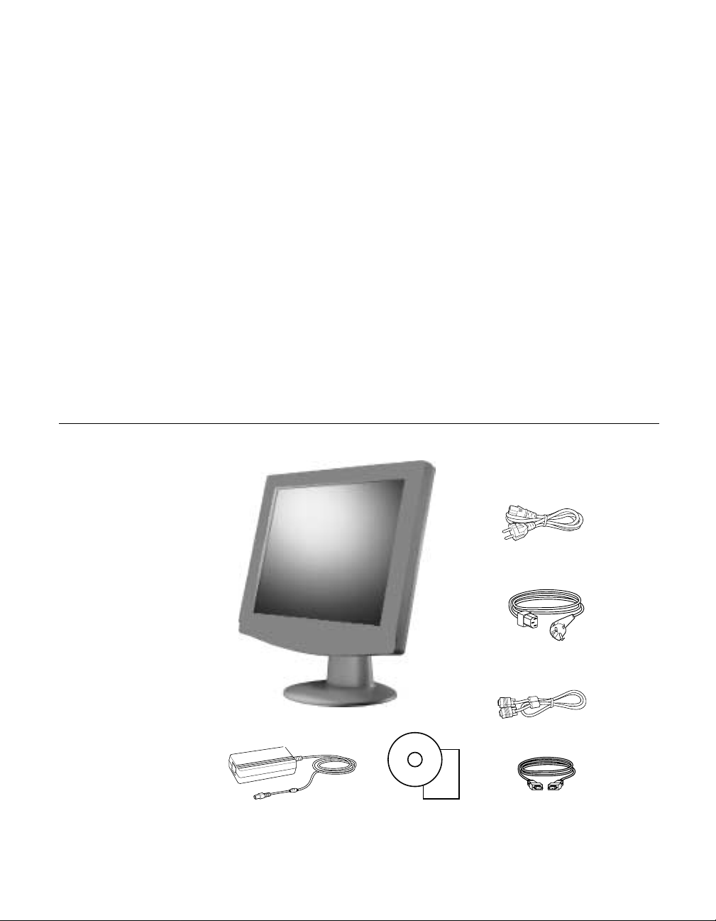
Unpac king Your Touchm onitor
C HAPTER
2
S
ETUP
AC/DC Power adapter
CD and Quick
Installation Guide
US power cord
European power cord
Video cable
Serial touchscreen
cable
2-3
Page 11
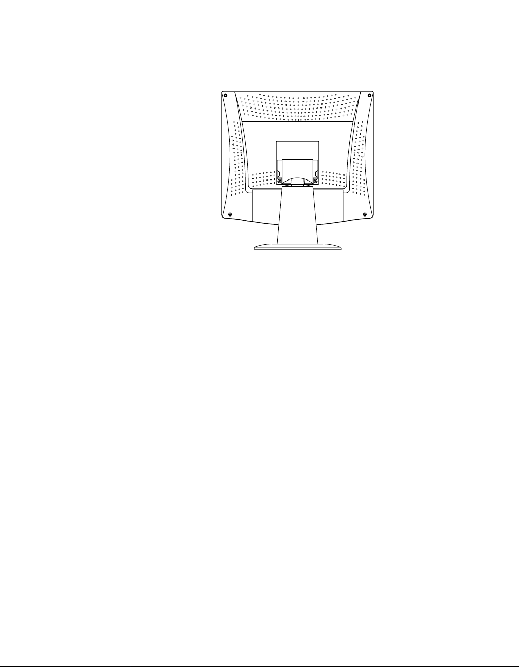
Rear View
2-4 Elo Entuitive Touchmonitor User Guide
Page 12
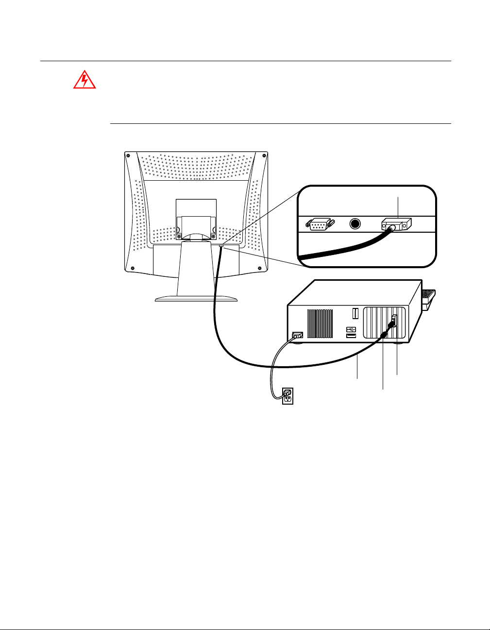
Conn ecting Your Touchmon itor
Before connecting the cables to your touchmonitor and computer , be sure that the
touchmonitor and com puter are off.
Vide o Cable Connect i o n
Connections on underside
Female 15-pin
video
D-SUB
Video
cable
Ferrite bead
Video
port
1 Set the touchmonitor on a solid hor izontal surface, such as a table or desk. 2 Connect the female end of the video cable connector to the back of the LCD
monitor, and connect the other end to the back of the computer.
3 Secure the ca ble to yo ur touc hmonitor a nd comput er by tight ening th e s crews
on the connector clockwise .
2-5
Page 13
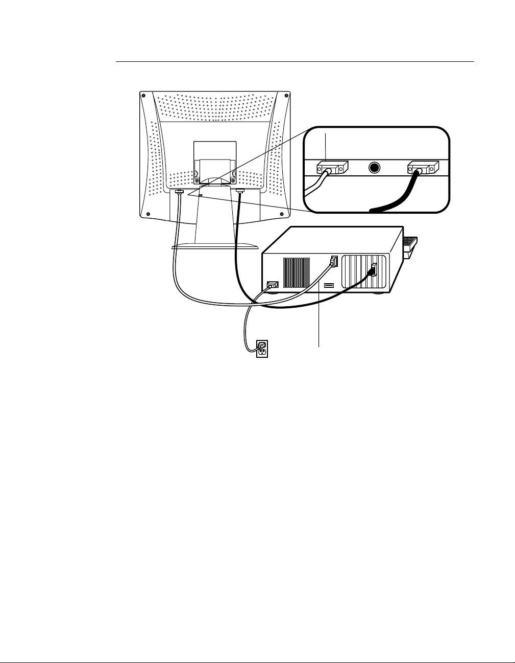
Touchscreen Cable Connection
Connections on underside
Female 9-pin serial
touchscreen
connector
Serial
touchscreen
cable
1 Connect the female end of the 9-pin touc hscreen RS-232 cable to the serial
port on the back of your computer.
2 Connect the male e nd of th e cable to t he s erial t ouchsc reen conne ctor on your
touchmonitor.
3 Secure the ca ble to yo ur touc hmonitor a nd comput er by tight ening th e s crews
on the connector clockwise .
2-6 Elo Entuitive Touchmonitor User Guide
Page 14
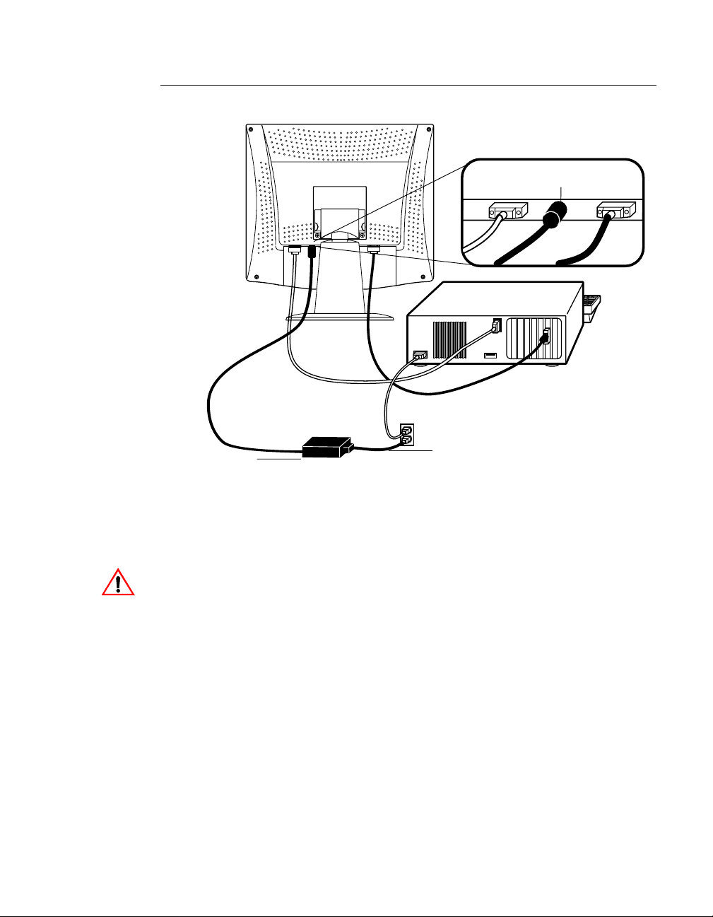
Po wer Cable Connection
Brick power supply
Connections on underside
DC 12V Brick power
cable port
Power
cable
1 Depending on where you live, you will use either the European or
US/Canadian powe r cable. Connect the female end of the power cable to the
Brick power supply.
2 Connect the Brick power supply into the power port on the touchmonitor.
To protect your equipment against risk of damage from electrical surges in the power
line, plug the Brick supply’s power cord into a surge protector, and then connect the
surge protector to a grounded (three-pronged) AC electrical outlet.
2-7
Page 15

Video Inp ut Pin Assig nme nt
This section describe s the pin assignment of the LCD’s 15 Pin Mini D-sub
(video cable) connector.
Pin No. Signal Connector
1 Red Video Signal
2 Green Video Signal
3 Blue Video Signal
4 N.C.
5 Ground
6 Ground for red video signal
7 Ground for green video sig nal
8 Ground for blue video sign al
9 N.C.
10 Ground
11 N.C.
12 DDC data
13 Horizontal sync signal
14 Vertical sync signal
15 DDC clock
2-8 Elo Entuitive Touchmonitor User Guide
Page 16

Installing the D river Soft ware
The driver software allows your touchmonitor to work with your computer.
Drivers are located on the enclose d CD-ROM for the following operating
systems:
• Windows XP
• Windows 2000
• Windows Me
• Windows 98
• Windows 95
• Windows NT 4.0
Your touchmonitor is plug-a nd-play compliant. Informati on on the video
capabilitie s of your touchmonitor is sent to your video display adapter when
Windows starts. If Windows detects your touchmonitor, follow the instructions
on the screen to install a generic plug-and-play monitor.
Refer to the appropriat e following section for driver installation instructions.
2-9
Page 17

N
Installing the Serial Touch Driver for Windows XP,
Windows 20001, Me, 95/98 and NT 4.0
OTE
:
For Win dows 2000 and NT 4.0 you must ha ve administrat or access rights to install the
driver.
1 Insert the Elo CD-ROM in your computer’s CD-ROM drive.
If the AutoStart feature for your CD-ROM drive is active, the system
automatically de tects the CD and starts the setup program.
2 Follow the directions on the screen to complete the driver setup for your
version of Windows.
If the AutoStart featu re is no t acti ve:
1 Click Start > Run. 2 Click the Browse button to locate the EloCd.exe program on the CD-ROM. 3 Click Open, then OK to run EloCd.exe. 4 Follow the directions on the screen to complete the driver setup for your
version of Windows.
1. To ins tall Windows 2000 and Windows XP, you must use the "update driver" meth od; you will not
find a setup.exe file with in the download.
2-10 Elo Entuitive Touchmonitor User Guide
Page 18

Installing the Serial Touch Driver for MS-DOS and Wind o ws 3. 1
You must have a DOS mouse driver (MOUSE.COM) installed for your mouse
if you wish to continue using your mouse along with your touchmonitor in
DOS.
To install Windows 3.x and MS-DOS from Windows 95/98, follow the
dire c t io ns be lo w:
1 Insert the CD-ROM in your computer’s CD-ROM drive. 2 From DOS, type d:\EloDos_W31 to change to the correct directory on the
CD-ROM (your CD-ROM drive may be mapped to a different drive letter).
3 Type install and press Enter to start the installation. 4 Align the touchscree n.
You must have already completed Steps 1 and 2 before proceeding.
To run the INSTALL program:
1 Type INSTALL at the DOS prompt in the directory containing the driver
inst a l l f i l e s .
2 INSTALL asks you to select the softwar e to install. Then choose
d:\EloDos_W31 from the displ ayed list.
3 INSTALL also asks you for the paths to use during ins tallation, or you may
use its defaults. INSTALL creates directories as necessary, and warns you if
they exist.
If you are updating your softwar e, you may wish to specify the paths conta ining
the earlier versi ons, and overwrite the obsolete files . All ex ecutable programs
are upward comp a tib le. Fo r a list of differences from each prev ious ve rsion of
the drivers, be sure to select "Differences from Previous Versions" during the
installation process.
INSTALL updates your AUTOEXEC.BAT file with the drivers you select.
INSTALL makes a copy of your original AUTOEXEC.BAT file, cal led
AUTOEXEC.OLD. If you already have Elo driver commands in your
AUTOEXEC.BAT file, they will be commented out.
When INSTALL is finished, it leaves a file called GO.BAT in the subdirectory
you specified. GO loads the touchscreen driver, runs the calibration program
ELOCALIB, and gives you some final instructions.
If you are using Windows 3.1, you will also calibrate the touchscreen within
Windows 3.1 with the Touchscreen Control Panel.
2-11
Page 19

2-12 Elo Entuitive Touchmonitor User Guide
Page 20

C HAPTER
3
C
HAPTER
3
O
PERATION
Variations in vide o output and application will likely require you to adj ust your
touchmonitor to optimi ze the quality of the display.
For best performance, your monitor should be operating in native resolution;
that is, 1280 x 1024 at 60 Hz. Use the Display control pan el in Windows to
choose 1280 x 1024 resolution.
Operating in other resolutions will degrade video performanc e. For further
information, please refer to Appendix A.
All adjustments you make to the controls are automatically memorized. This
feature saves you from having to rese t your choices every time you unplug or
power your touchmonitor off and on. If there is a power failure, your
touchmonitor settings will not default to the factory specifications.
3-13
Page 21

Touchmo nitor Con tr ols
Setting th e Re fre sh R at e
Follow the instructions below to set your refresh rate in Windows 98.
LED Indicator Soft Power Switch
1 Go to the configuration window (Start>Settings>Configuration window). 2 Double-click on the Display ico n. 3 Click on the Settings tab. 4 Click on the Advanced button. 5 Click on Adapter and select 60Hz from the list. 6 Click on Apply to accept the select ed value.
3-14 Elo Entuitive Touchmonitor User Guide
Page 22

Adjustments
All adjustments are made using the on-s creen display (OSD) controls.
1280X1024
V:60.0/H:63.9
BRIGHTNESS
Menu Select
Figure 3.1
Touchmonitor Controls
Control Function
Power
Menu
Select
Adjust
Adjust
Power LED
Press the power key to turn the monitor on. Press it again to turn the
monit o r of f.
Activate the OSD adjustment menu. Move from the submenu back to the
previo us m enu.
To select the adjustment items from the OSD menu.
To scroll up in the menu or to increase the value of the selected item.
To scroll down in the menu or to de crease the value of the selected item.
The LED will be gr een when the monitor is in the normal ON mode, and
will be orange when it is in t he power saving m ode.
3-15
Page 23

Screen Ad justments
The setting switches are normally in stand-by mode.
1 Push the MENU button once to display the OSD screen. The resolution and
frequency are displ ayed at the top of the menu box.
2 Push the or button to select the item you want to adjust. The selected
item will be highlighte d.
3 Push the SELECT button to adjust the highlighted item. 4 Push the or button to adjust the sele ction. 5 After making the adjustment, push the MENU button to return. 6 The display unit automatic ally saves the new settings in 1 second after your
last adjustment and the menu disappears. You can also push the MENU
button to make the menu disappear.
Direct Access Buttons
Auto Adjust
To display a full screen, such as Window’s background. Press the SELECT
(AUTO) button to adjust the shape of the scr een aut omatically.
3-16 Elo Entuitive Touchmonitor User Guide
Page 24

OSD Lock/Unlock
This function allows you to loc k and unlock the OSD options.
1 Press the MENU and Power button together for 2 or 3 seconds. 2 Select the OL icon. 3 Select Yes. 4 Power the mon itor o ff the n on . 5 Press the MENU button. The status is OSD lock on the user mode.
To Unlock the OSD:
1 Press the MENU and Power button together for 4 or 5 seconds on the OSD
lock statu s .
Po wer Lock/Unlock
1 Press the MENU and Power button together for 2 or 3 seconds. 2 Press the MENU button and select the PL icon. 3 Select Yes. 4 Press the MENU button and select the OL icon. 5 Select No. 6 Power the mon itor o ff the n on . 7 Press the Power button. The status is Power lock on the user mode.
To Unlock the Power:
1 Press the MENU and Power button together for 4 or 5 seconds on the Power
lock statu s .
3-17
Page 25

OSD and Power Lock/Unlock
1 Press the MENU and Power button together for 2 or 3 seconds. 2 Press the MENU button and select the PL icon. 3 Select Yes. 4 Power the mon itor o ff the n on . 5 Press the MENU and Power button. The status is OSD and Power lock on
the user mode.
To Unlock the OSD and Power:
1 Press the MENU and Power button together for 4 or 5 seconds on the OSD
and Power lock status.
3-18 Elo Entuitive Touchmonitor User Guide
Page 26

OSD Adjustments
The OSD adjustments available are listed below.
BRIGHTNESS
Adjusts the brightness of the screen.
CONTRAST
Contrast allows you to adjust the diff erence between black and white shades for
image sharpn ess .
COLOR CONTROL
Color temperature aff e cts the tint of the image. With lower color temperature s,
the image turns reddish, with higher temperatures the image turns bluish.
There are thre e color settings available : Mode 1(a cool white), Mode 2 (a warm
white), or USER. The USER sett ing allows you to set individua l values for red,
green, and blue.
YUV COLOR
Color technology allows use rs to make the following color adjustment.
HUE
Adjusts the hue of the video image.
FLESH TONE
Adjusts the flesh tone of the video image.
MISCELLA NE OU S
RECALL
Recalls the saved color data.
OSD TIMER
Sets the displayed time of the OSD Menu window on the screen.
OSD POSITION
Adjusts the OSD menu’s horizonta l or vertical position on the screen.
3-19
Page 27

AUTO ADJUST
Adjusts the shape of the screen automatically at the full screen pattern.
LANGUAGE
Select the language in which adjustment menus are displayed. The following
languages are available: English, French, German, Italian, Spanish and
Japanese.
H/VPOSITION
H-POSITION
H-Position adjusts the horizontal position of the entir e screen.
V-POSITION
V-Position adjusts the vertical position of the entire scre en.
CLOCK PHASE
PHASE
Adjusts the noise of the screen image.
CLOCK
Adjusts the horizo n tal size of the ent ire sc ree n ima ge.
3-20 Elo Entuitive Touchmonitor User Guide
Page 28

C
HAPTER
4
T
ROUBLESHOOTING
If you are experiencing trouble with your touchmonitor, refer to the following
table. If the problem persists, please contact your resel ler or our technical
support at 1-800-557-1458.
Problem Suggestion(s)
No image appears on screen.
Error message: Video mode not
supported
The display does not enter the power
management mod e
Message: No signal
Check that the video cable an d pow er connectors are properly
connected as descri bed in Chapte r 2.
Make sure the pins of the connectors are not crooked or
broken.
Check that pow er switch of the touchmonitor has be en pressed
and LED on the front of touchmonitor is lit.
Test the powe r supply by trying different cables, or a di fferent
wall outlet or plug another appliance into the outlet.
Make certain the video cable is proper ly connected and that it
is not damaged. Check for bent pins on the cable connectors.
Ensure tha t your computer and video card are properly
configured (consult video card documentation) and the video
card is firmly seate d in the card slot of the com puter
motherboard.
Check the res olution and t he frequency on the video port of
your computer.
Compare these values with the data in the Preset Timing Table.
The video signal from the computer does not com ply with
VESA DPMS standa rd. Either the computer or the graphics
adapter is not using the VESA DPMS pow er management
function.
Check that the signal cabl e connector is properly connected
and that the connection pins are not bent or dam aged.
If the connector is loose, tighten the connector screws. Check
that the computer is switched on.
C HAPTER
4
T
IPS
4-21
Page 29

Problem Suggestion(s)
Duplicated images
Partial image or incorrectly displayed
image
Image is un sta ble a nd flic ker ing
Image is scroll in g
Touch does not work
There is a problem with your graphics adapter or display unit.
Contact your service representative.
Check whether the resolution of your computer is higher than
that of the LCD touchmonitor.
Check that the video cable from the monitor has been secure ly
and corr ectl y co nne cted to the vi de o c onne ctor at the r ea r o f the
computer.
Reconfigure the resolution of your computer to make it less
than or equal to 1280 x 1024. See Appendix A for more
informat ion on resolution.
Check and reconfigure the touchmonitor mode of the vertical
refres h rate of your gr aphic c ard to mak e it com pa tibl e wit h the
LCD touchmonitor.
Check that the display resolution and frequency from your PC
or graphic adapter is an available mode for your monitor. You
can check this through the Windows Control Panel. From the
Control Panel click on Display, then Settings.
Make sure the VG A signal ca ble (or adapt er ) is we ll conne ct ed.
Check and reconfigure the display mode of the vertical refresh
rate of your graphic card to make it compatible with the LCD
touchmonitor.
Make sure the touchscreen cable is secu rely connected at both
ends.
4-22 Elo Entuitive Touchmonitor User Guide
Page 30

A PPENDIX
A
C
HAPTER
4
N
ATIVE
The native resolution of a monitor is the resolution at which the LCD panel is
designed to perform best. In almost all cases, screen images look best when
viewed at their native resolution. You can lower the resolution setting of a
monitor but not increase it. For the Elo LCD touchmonitor, SXGA-17 inch, the
native resolut ion is 1280 x 1024.
Input Vi d e o 17" LCD
640 x 480 (VGA) Transforms input format to 1280 x 1024 size
800 x 600 (SVGA) Transforms input format to 1280 x 1024 size
1024 x 768 (XGA) Transforms input format to 1280 x 1024 size
1280 x 1024 (SXGA) Displays in native resolution
R
ESOLUTION
The native resolution of an LCD is the resolution that matches the LCD’s
pixels. Video performance is always best at native resolution settings. The
various standard LCD resol utions are usually represent ed as foll ows:
VGA
SVGA
XGA
SXGA
640 x 480
800 x 600
1024 x 768
1280 x 1024
A-23
Page 31

For example, a SVGA resolution LCD panel displays 800 pixels horizontally
and 600 pixels vertical ly. Input video is also represented by the same terms .
XGA input video has a format of 1280 pixels horizonta lly by 1024 pixels
vertically . When the input pixe ls contained in the video input format match the
native resolut ion of the panel, there is a one-to-one corre spondence of mapping
of input video pixels to LCD pixels. For example, the pixel in 45 column and 26
row of the input video is in 45 column and 26 row of the LCD. When the input
video is set at a lower resoluti on than the native resolution of the LCD, the
direct corresponde nce between the video pixels and the LCD pixels is lost. The
LCD controller c an compu te the correspon dence be tween video pi xels a nd LCD
pixels using algorithms contained in the controller. The accuracy of the
algorithms determines the fidelity of conversion of video pixels to LCD pixels.
Poor fidelity conve rsion can result in artifacts in the LCD displa y, suc h as
characters of varying width.
A-24 Elo Entuitive Touchmonitor User Guide
Page 32

A PPENDIX
B
C
HAPTER
4
T
OUC HMON ITOR
This manual contains inf ormation that is important for the proper setup and
maintenance of your touc hmonitor. Befor e setti ng u p and poweri ng on your new
touchmonitor, read thr ough this manual, especia lly Chapter 2 (Insta llati on), and
Chapter 3 (Ope rati o n).
CAUTION !!
S
AFET Y
RISK OF ELECTRIC SHOCK
DO NO T O PEN
CAUTION:
1 Turn off the touchmonitor before cleaning.
2 Your brick supply is equipped with a 3-wir e, grounding power cord. The
power cord plug will only fit into a thre e-pr ong safety ground outlet. Do not
attempt to fit the plug into an outl et that has not been configured for this
purpose. Do not use a damaged power cord. Use only the power cord that
comes with your Elo TouchSystems touchmo nitor. Use of an unauthorized
power cord may invalidate your warranty.
To reduce the risk of electric shock, do not
remove cover (or back).
No user serviceable parts inside.
Refer servici ng to qualified personnel
B-25
Page 33

3 This display should be inst alled on a solid horizontal base.
4 Adequate ventilation must be maintained to ensure reliable and continued
operation and to protect the display from overheating. Do not block
ventilation slots and openings with objects or install the display in a place
where ventilation may be hind ered.
5 This display should be operate d from the type of power source indicated on
the AC/DC adapter.
6 Do not install this display near a motor or transformer where strong
magnetism is g enerated. Images on the display will be come distorted and the
color irr egula r.
7 Do not allow metal pieces or objects of any kind fall into the display from
ventilation holes.
8 Do not attempt to service this unit yourself. Removal of the display cover
may expose you to dangerous voltage or other ri sks. Refer all servicing to
qualified service personnel.
9 Unplug this product from the wall outle t and refer servicing to qualified
service personnel in the event tha t:
1 Liquid is spilled into th e product or the product is expos ed to rain or wa ter.
2 The product does not operate nor mally when the operati ng instructi ons a re
followed.
3 The product has been dropped or the cabinet has been damaged.
4 The product exhibits a distinct change in performance, indicating a need
for service.
5 Power cord or plug is damaged or frayed.
B-26 Elo Entuitive Touchmonitor User Guide
Page 34

Care an d Handling of Your Touchm onitor
The following tips will help keep your Elo Entuitive touchmonitor functioning
at the optimal level.
• To avoid risk of electric shock, do not disassemble the brick supply or
display unit cabine t. The unit is not user serviceable. Remember to unplug
the display unit from the power outlet before cleaning.
• Do not use alcohol (methyl, ethyl or isopropyl) or any strong dissolvent. Do
not use thinner or benzene, abra sive cleaners or compressed air.
• To clean the brick supply or display unit cabinet, use a cloth lightly
dampened with a mild detergent .
• Avoid getting li quids i nside your brick sup ply or touchmonit or. I f liqui d does
get inside, have a qualif ied service techni cian check it befo re you power it on
again.
• Do not wipe the screen with a cloth or sponge that could scratch the surface.
• To clean the touchscreen, use window or glass cleaner. Put the clean er on the
rag and wipe the touchscreen . Never apply the cleaner directly on the
touchscreen.
B-27
Page 35

B-28 Elo Entuitive Touchmonitor User Guide
Page 36

Preset Timing Table
Your Elo Entuitive touchmon itor is compatible with the following standa rd
video modes. All specifications are typical and subject to change .
Table C.1
Analog R.G.B. Input.
Number Resolution Horizontal Frequency
1 720 x 400@70H z 31.5KHz
2
3 640 x 480@75H z 37.5KHz
4
5 800 x 600@60H z 37.9KHz
6
7 800 x 600@75H z 46.9KHz
8
9 1024 x 768@60Hz 48.4KHz
10
11 1024 x 768@75Hz 60.0KHz
12
13 1280 x 1024@60Hz 63.9KHz
14
640 x 480@60H z 31.5KHz
800 x 600@56H z 35.2KHz
800 x 600@72H z 48.1KHz
832 x 624@75H z 49.7KHz
1024 x 768@70Hz 56.5KHz
1152 x 870@75Hz 68.7KHz
1280 x 1024@75Hz 80.0KHz
C
HAPTER
4
T
ECHNICAL
A PPENDIX
C
S
PECIFICATIONS
C-29
Page 37

VESA Mounting
This display unit supports VESA FPMPMI standard for 100mmx100mm screw
mounting by giving four screw holes inside the base stand of the unit. The base
stand must be removed before connecting to the Speciality Flat Panel Monitor
Mounting Device.
C-30 Elo Entuitive Touchmonitor User Guide
Page 38

Touchmonitor Specifications
Display Type
Recommended
Resolution
Maximum
Resolution
Frequency Rate
Maximum
Bandwidth
Display area
LCD display color
OSD menu
Brightness
Response time
AC/DC adapt er
Input signals
Power consumption
Power management
Input connector
Regulation
Dimensions
Weight
Accessories
Temperature
17” TFT
1280 x 1024@60H z
Analog RGB: 1280x1024@75Hz
Horizontal: 31.0 to 80.0KH z
Vertical: 56 to 7 5 H z
135 MHz
337.92 x 270.336 mm
16.7M Colors max.
Brightness, Contrast, Color control, YUV color, Miscellaneous,
Auto adjust, Language, H./V. Position, Clock phase
250 cd/ m²/panel
237 cd/m
200 cd/m
25ms typ.
Input DC12V ~ 3.75A
R.G.B. Analog
45W
VESA DPMS
15 Pin D-Sub.
UL, CUL, TÜV- GS, FCC, CE, C-Tick, VCCI, IC UL- A R/S, CB,
TCO99
420 mm (W) x 437 mm (H) x 220 mm (D).
8.0kgs. unpacked; 10.75kgs. packed
VGA cable, AC/DC adapter, US and Europe an power c ord , t ouc h
cable.
Operation 5 ~ 45°C
Storage 20 ~ 60°C
² IntelliTouch (95%)
² AccuTouch (80%)
Plug & Play
VESA DDC 1/2B
C-31
Page 39

AccuTouch Touchscreen Specifications
Mechanical
Positional Accuracy Standard deviation of error is less than 0.080 in. (2.03 mm). Equates to
Touchpoin t Density More than 100,000 touchpoint s/in
Touch Activation Force Typically less than 4 ounces (113 grams).
Surface Dur ability Surface durabili ty is that of glass, Mohs’ hardness rating of 7.
Expected Life Performance AccuTouch technology has been operationally tested to more than 35
Sealing Unit is sealed to protect against splashed liquids, dirt, and dust.
Optical
Light Transmission (per ASTM D1003) 80%; ±5%
Visual Resolution All measurements made using USAF 1951 Resolution Chart, under 30X
Gloss (per ASTM D2457 using a
60-degr ee gloss meter)
Environmental
Chemical R esistance The acti ve area of the touchscreen is resistant to all chem icals that do not
Electrostatic Protection
(per EN 61 000-4-2)
less than ±1%.
million touches in one location without failure, using a styl us similar t o a
finger.
magnifi cation, wit h test unit located approximately 1.5 in (38 mm) from
surfac e of resolution chart.
Antiglare surface: 6:1 minimum.
Antigl are surface: Flat: 90 ± 20 gloss units.
affect glass, such as:
Acetone
Methylene chloride
Methyl ethyl ketone
Isopropyl alcohol
Hexane
Turpentine
Minera l sp ir its
Unleaded Gasoline
Diesel Fuel
Motor Oil
Transmis sion Fluid
Antifreeze
Ammo ni a based glass cl ea n er
Vinegar
The touchs creen withst ands 20 discharges of 15KV, distributed randomly
across the active area of the touchscreen with proper transi ent protection.
2
(15,500 touchpoints/cm2).
See http:/www.elotouch.com/products/accutec/accuspec.asp for comple te and
updated specifications.
C-32 Elo Entuitive Touchmonitor User Guide
Page 40

IntelliT ouch Touchscreen Specifications
Mechanical
Positional Accuracy Standard deviation of error is less than 0.080 in. (2.03 mm). Equa tes to less than
Touchpoint Density More than 100, 000 touchpoints/in
Touch Activa tion Force Typically less than 3 ounce s (85 grams).
Surface Dur ability Surface durability is that of glass, Mohs’ hardness rating of 7.
Expected Life
Performance
Sealing Unit is sealed to protect against splashed liquids , dirt, and dust.
Optical
Light Transmission (per
ASTM D1003)
Visual Reso lution All measurements made using USAF 1951 Resolution Chart, under 30X
Gloss (per A STM D2457
using a 60-de gree gloss
meter)
Environmental
Chemical Resis ta nce The active area of t he t ouch scree n is res ista nt to all ch emi cal s th at do not aff ect gl as s,
Electrosta tic Protection
(per EN 61 000-4-2,
1995)
±1%.
No known wear-out mechanism, as there are no layers, coatings, or movin g parts.
IntelliTouch technol ogy has been operationally tested to more than 50 million
touches in on e location wit hout failure, using a stylus similar t o a finger.
95%
magnifica tion, with test unit located approximately 1.5 in (38 mm) from surface of
resolution ch a rt.
Antiglare surface: 6:1 minimum.
Antiglare surface: Flat: 85 ± 20 gloss units.
such as:
Acetone
Toluene
Methyl ethy l ketone
Isopropyl alcohol
Methyl alco hol
Ethyl acetate
Ammonia-based glass cleaners
Gasoline
Kerosene
Vinegar
Meets Level 4 ( 15 kV air/8 kV contact discharges).
2
(15,500 touchpoints/ cm2).
See http://www.elotouch.com/products/inteltec/intelspe c.asp for complete and
updated specifications.
C-33
Page 41

17" LCD Desktop Touchmonitor (ET1724L-XSWB-1) Dimen sions
420
340
171
272
371
240.0
373
437
42
C-34 Elo Entuitive Touchmonitor User Guide
130
70
247
220
Page 42

110
41
N
OTE
:
Dimensi o ns in millimeters
C-35
Page 43

C-36 Elo Entuitive Touchmonitor User Guide
Page 44

C
HAPTER
4
R
EGULATORY INFORMATION
I. Electrical Safety In fo r mation:
A) Compliance is required with respect to the voltage, frequency, and current
requirements indicated on the manufacturer’s label. Connection to a different
power source than those specified herein will likely result in improper operation,
damage to the equipment or pose a fire hazar d if the limitations are not followed.
B) There are no ope rator serviceable parts i nside this equipment. There are hazardous vol tages generated by th is equipment which constitute a safety hazard. Service
should be provided only by a qualified service technician.
C) This equipment is pro v ided with a detachable power cord whi ch has an integral
safety ground wire and 3-prong connector intended for connection to a grounded
safety outlet.
1) Do not substi tute the cord with othe r than the provide d app roved t ype.
Under no circumstances use an adapter plug to connect to a 2-wire outlet as
this will defeat the continuity of the grounding wire.
2) The equipment requires the use of the ground wire as a part of the safety
certification, modification or misuse can provide a shock hazard that can
result in serious injury or death.
3) Contact a qualified electrician or the manufacturer if there are questions
about the installation pr ior to connecting the equipment to mains powe r.
II. Emissions and Immunity Information
A) Notice to Users in the United States: This equipment has been tested and found
to comply with the limits for a Class B digital device, pursuant to Part 15 of FCC
Rules. These limits are designed to provide reasonable protection against harmful
interference in a residential installation. This equipment generates, uses, and can
radiate radio frequency energy, and if not inst alled and us ed in accordance with the
instructions, may cause harmful interference t o radio communications .
B) Noti ce to User s in Canada: This equipment complies with the Cla ss B limits for
radio noise emissions from digital apparatus as established by the Radio Interference Regulations of Ind ustrie Canada.
C) Notic e to U se rs in th e E ur o pe an Unio n: Use on ly the provid ed power cords and
interconnecting cabling provided with the equipment. Substitution of provided
cords and cabling may compromise electrical safety or CE Mark Certification for
emission s or immunity as required by the following standar d s:
This Inform ation Technology Equipment (ITE) is required to have a CE Mark
on the manufacturer’s label which means that the equipment has been tested
to the following Directiv es and Standards:
37
Page 45

This equipment has been tested to the requirements for the CE Mark as
required by EMC Directive 89/336/EEC indicated in European Standard EN
55 022 Class B and the Low Voltage Directive 73/23/EEC as indicated in
European Standard EN 60 950.
D) General Information to all Users: This equipment generates, uses and can radiate radio frequency energy. If not installed and used according to this manual the
equipment may cause interference with radio and television communications.
There is, however, no guarantee that interference will not occur in any particular
instal lation due to site-specific fa ctors.
1) In order to meet emission and immunity requirements, the user must
observe the following:
a) Use only the provided I/O cables to connect this digital device with
any computer.
b) To ensure compliance, use only the pr ovided manufacturer ’s approved
line cord.
c) The user is cautioned that changes or modifications to the equipment
not expressly approved by the party responsible for compliance could
void the user’s authority to operate the equipment.
2) If this e quipment ap pears to c ause interference with radio or tel evision
reception, or any othe r device:
a) Verify as an emission sou rce by turni ng the equipment off and on.
b) If you de te r m in e th a t th is equ i pm e n t is cau s in g the int er fe rence, tr y to
correct the interference by using one or more of the f o llowing measures:
i) Move the digital device away from the affected receiver.
ii) Reposition (turn) the digital device with respect to the affected
receiver.
iii) Reorient the af fected receiver ’s antenna.
iv) Plug the digital device into a different AC outlet so the digital
device and the receiver are on different branch circuits.
v) Disconnect and remove any I/O cables that the digital device
does not use. (Unterminated I/O cables are a potential source of
high RF emission levels.)
vi) Plug the digital device into only a grounded outlet receptacle.
Do not use AC adapter plugs. (Removing or cutting the line cord
ground may increase RF emission levels and may also present a
lethal shock hazard to the user.)
If you need additional help, consult your dealer, manufacturer, or an experienced radio or televi sion technic ian.
38 Elo Entuitive Touchmonitor User Guide
Page 46

IC ES03
39
Page 47

40 Elo Entuitive Touchmonitor User Guide
Page 48

INDEX
Numerics
17" LCD Desktop Touchmonitor (ET1724L-XSWB-1)
Dimensions, 34
A
About the Product, 1
AccuTouch Touchscreen Specifications ,32
Adjustments, 15
AUTO ADJUST, 20
Auto Adjust, 16
B
BRIGHTNESS, 19
C
Care and Handling of Your Touchmonitor,27
Chemical Resistance, AccuTouch, 32
Chemical Resistance, IntelliTouch, 33
CLOCK, 20
CLOCK PHASE, 20
COLOR CONTROL, 19
Connecting Yo ur Touchmonitor, 5
CONTRAST, 19
D
Direct A c ce ss B uttons, 16
Display Timing, 31
E
Electrical Safety Information,37
Electrostatic Protection, AccuTouch, 32
Electrostatic Protection, IntelliTouch, 33
Emissions and Immunity Information, 37
Expecte d Life Perf orm a nc e, AccuTo uc h, 3 2
Expecte d Li fe P erforma nc e, Int el li Touch, 33
F
FLESH TONE, 19
G
Gloss, AccuTouch,32
Gloss, IntelliTouch, 33
H
H/VPOSITION, 20
H-POSITION, 20
HUE, 19
I
Instal lation an d Setup, 3
Installing the Driver Software, 9
Installing the Serial Touch Driver for MS-DOS and
Windo ws 3.1, 11
Installing the Serial Touch Driver for Windows XP,
Windows 2000, Me, 95/98 and NT 4.0, 10
Introduction, 1
L
LANGUAGE, 20
Light Transmission, AccuTouch, 32
Light Trans mi ssi on , Inte lli To uc h, 33
M
MISCELLA NEOUS, OSD Adjustments, 19
N
Native Resolution, 23
O
Operation, 13
OSD Adjustments,19
OSD and Power Lock/Unlock, 18
OSD Controls, 15
OSD Lock/Unlock, 17
OSD POSITION, 19
OSD TIMER, 19
P
PHASE, 20
Positional Accuracy, AccuTouch, 32
Positional Ac cur acy , Inte ll iTo uch , 33
Power Cable Connection, 7
Power Lock/Unlock, 17
Precautions, 1
Preset T im in g Table, 29
Product Description,1
R
Rear View, 4
Regulatory Information, 37
Resolution, 29
Index-41
Page 49

S
Screen Adjustments, 16
Sealing, Accutouch,32
Sealing, IntelliTouch, 33
Setting the Refresh Rate, 14
Surfac e Dur a bi lity, Accu Touch, 32
Surface D ur a bi lit y, Intelli Touch, 33
SVGA, 23
T
Technical Specifications, 29
Touch Activation Force, AccuTouch, 32
Touch Activation Force, IntelliTouch, 33
Touchmonitor Controls, 14
Touchmonitor Safety, 25
Touchmonitor Specifications, 31
Touchpoint Density, AccuTouch, 32
Touchp oi nt D en si ty , In te ll iT o uc h , 33
Touchscreen Ca ble Connec tion, 6
Troubleshooting Tips, 21
U
Unpacking Your Touchmonitor, 3
V
VESA Mounting, 30
VGA, 23
Video Cable Connection,5
Video Input Pin Assignment, 8
Visual Resolution, AccuTouch, 32
Visual Resolution, IntelliTouch, 33
V-POSITION, 20
X
XGA, 23
Index-42
Page 50

 Loading...