

Elo TouchSystems ET1545L-XXWC-X, ET1547L-XXWC-X, ET1567L-XXWC-X, ET1548L-XXWC-X, ET1549L-XXWC-X User Manual
Page 1
Page 2
Elo Entuitive Touchmonitor
User Guide
15" LCD Rear and Front Mount Touchmonitors
ET1545L-XXWC-X Series
ET1547L-XXWC-X Series
ET1548L-XXWC-X Series
ET1549L-XXWC-X Series
ET1567L-XXWC-X Series
Revision E
P/N 0085 21
Elo TouchSystems, Inc.
1-800-ELOTOUCH
www.elotouch.com
Page 3

Page 4

Copyright © 2002 Elo TouchSystems Inc. All Rights Reserved.
No part of this p ublic ation ma y be repr oduce d, tra nsmitte d, transc ribe d, stor ed in a ret rieval system,
or translated into any language or computer language, in any form or by any means, including, but not
limited to, electronic, magnetic, optical, chemical, manual, or otherwise without prior written
permission of Elo TouchSystems.
Disclaimer
The information in this document is subject to change without notice. Elo TouchSystems makes no
representations or warranties with respect to the contents hereof, and specifically disclaims any
implied warran ties of merchan tabili ty or fitnes s for a partic ular pu rpose. El o TouchSystems re serves
the right to revise this publication and to make changes from time to time in the content hereof
withou t ob l igation of Elo TouchS ys tems to no tify any per s on of such rev is i o n s or ch anges.
Trademark Acknowledgments
IntelliTouch, SecureTouch, AccuTouch, Entuitive, and MonitorMouse are trademarks of Elo
TouchSystems, Inc.
Other product names mentioned herein may be trademarks or registered trademarks of their
respective companies. Elo TouchSystems claims no interest in trademarks other than its own.
3
Page 5

4
Page 6

Table of Contents
Chapter 1
Introduction 1
Precautions . . . . . . . . . . . . . . . . . . . . 1
About the Product . . . . . . . . . . . . . . . . . 1
Chapter 2
Installation and Setup 3
Unpacking Your Touchmonitor. . . . . . . . . . . 3
Product Ov ervi ew (1545L). . . . . . . . . . . . . 4
Main Unit . . . . . . . . . . . . . . . . . . . . 4
Rear View . . . . . . . . . . . . . . . . . . . 4
Bottom View/Side View . . . . . . . . . . . . 5
Product Ov ervi ew (1547L/1548L/1549L) . . . . . 5
Main Unit . . . . . . . . . . . . . . . . . . . . 5
Rear View . . . . . . . . . . . . . . . . . . . 6
Side View. . . . . . . . . . . . . . . . . . . . 6
Product Ov ervi ew (1567L). . . . . . . . . . . . . 7
Main Unit . . . . . . . . . . . . . . . . . . . . 7
Rear View . . . . . . . . . . . . . . . . . . . 7
Side View. . . . . . . . . . . . . . . . . . . . 8
Attaching the L-Brackets . . . . . . . . . . . . . 9
Touch Int erface Connection . . . . . . . . . . . 10
Serial Connection . . . . . . . . . . . . . . 10
Connecting the Video Cable . . . . . . . 11
Connecting the Serial Touchscreen Cable 12
Connect the Remote OSD Cabl e . . . . . 13
Connecting the Power Cable . . . . . . . 14
USB Connection . . . . . . . . . . . . . . . 15
Connecting the Video Cable . . . . . . . 16
Connecting the USB Touchscreen Cable . 17
Connecting the Remote OSD Cable . . . 18
Connecting the Power Cable . . . . . . . 19
Optimizing the LCD Display . . . . . . . . . . . 20
VESA Mount on Your Touchmonitor. . . . . . . 20
Installing the Driver Software . . . . . . . . . . 21
Installing the Serial Touch Driver for Windows
XP, Windows 2000, Me, 95/98 and NT 4.0 . 22
Installin g the Serial Touch Driver for MS- DOS
and
Windows 3.1 . . . . . . . . . . . . . . . 23
Installi ng th e USB Touch Driver . . . . . . . 24
Installing the USB Touch Driver for Windows
98 and Windows 2000 . . . . . . . . . . 24
Chapter 3
Operation 25
About Touchmonitor Adjustments. . . . . . . . 25
Using the On-Screen Di splay Menus . . . . . . 25
OSD Menu Function . . . . . . . . . . . . . . 27
Chapter 4
Troubleshooting 29
Solutions to Common Problems . . . . . . . . 29
Appendix A
Appendix B
Care and Handling of Your Touchmonitor. . . . 34
Appendix C
Compatibility Modes . . . . . . . . . . . . . . 35
Touchmonitor Specifications ET1545L/1547L/
1548L/1567L . . . . . . . . . . . . . . . . . 36
Touchmon it or Specifications ET1549L . . . . . 37
15" LCD Touchmoni tor Dimensions. . . . . . . 40
ET1545L . . . . . . . . . . . . . . . . . . . 40
ET1547L/1548L/1549L . . . . . . . . . . . 41
ET1567L . . . . . . . . . . . . . . . . . . . 43
Cut Out Dimensions . . . . . . . . . . . . . 44
ET1545L Front Mount Cut Out . . . . . . 44
ET1545L Rear Mount Cut Out . . . . . . 45
ET1547L/1548L/154 9L Rear Mount Plat e Cut
Out . . . . . . . . . . . . . . . . . . . . 45
ET1567L Front Mount Plate Cut Out . . . 46
Regulatory Information 47
Warranty 51
Inde x 53
1
Page 7

Congratulati ons on your purchase of an Elo TouchSystems Entuitive LCD
touchmonitor. Your new high-resolution touchmonitor combines the reliable
performance of Elo’s touch technol ogy with the latest advances in LCD display
design. This combination of features creates a natural flow of information
between a user and your touchmonit or.
Precautions
C HAPTER
1
C
HAPTER
1
I
NTRODUCTION
Follow all warnings, precautions and maintenance as recommended in this
user’s manual to maximize the life of your unit. See Appendix B for more
information on touchmon itor safety.
Abou t the Pr oduct
Your LCD Kiosk Touchmonitor is a 15.0” XGA TFT color display with the
following feature s:
• Direct analog RGB input
• 15.0” diagonal screen size
• 16.7 million displayable colors (262,144-1549L)
• 1024 x 768 resolution
• XGA/ SVGA/ VGA/ VESA/ Mac/ NEC PC-98 compatible
• 24~60kHz horizontal scan
• 56~75Hz refresh rate
1-1
Page 8

• Auto adjustment capability
• High quality full scree n re- scaling
• Multilingual OSD menus in four languages: English, French, Italian,
Spanish, and Japanese
• VESA flat panel monitor physical mou nting interface (75mm)
• For full Product Specif ications refer to Appendix C.
1-2 Elo Entuitive Touchmonitor User Guide
Page 9
C
HAPTER
2
I
NSTALLATION AND
Unpac king Your Touchm onitor
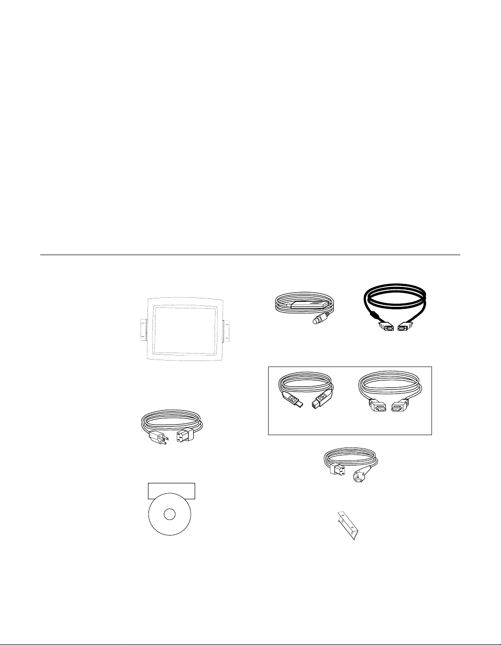
Check that the following 9 items are present and in good condition:
C HAPTER
2
S
OSD Remote Video cable
ETUP
LCD Display
Monitor power cable (US/Canada)
Elo Quick Install Guide
CD
Software
Quick Install Guide and software CD
OR
USB touchscreen
cable
European monitor power cable
Mounting brackets (2)
Serial touchscreen
cable
2-3
Page 10
Prod uct O verview (1545L)
Main Unit
LCD Display
Detachabl e mounting L-brackets
Rear View
2-4 Elo Entuitive Touchmonitor User Guide
Page 11
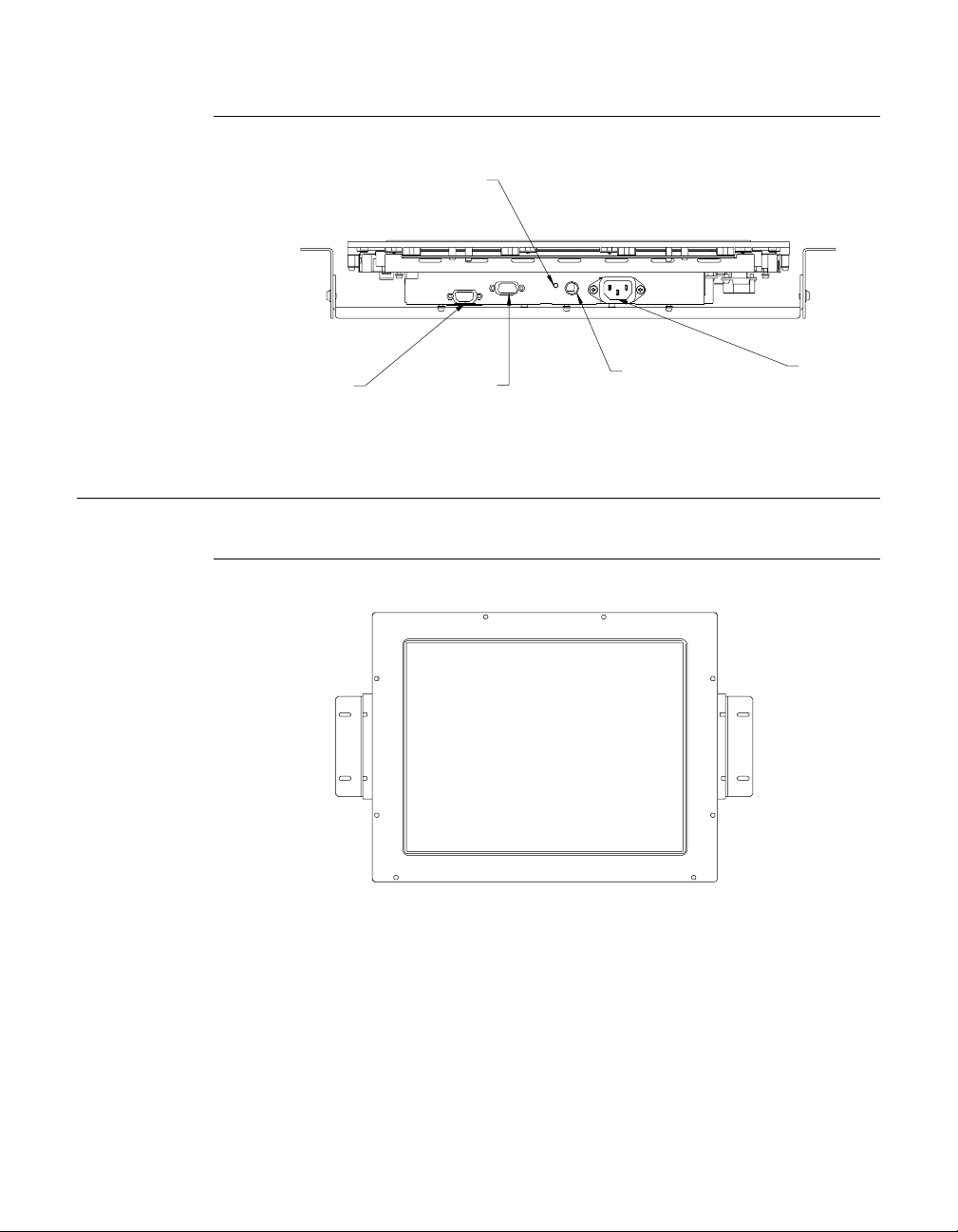
Bottom View/Side View
r
Power
switch
Touch interface
serial
Video cable
connector
Prod uct O verview (1547 L/1548 L/1549L )
Main Unit
Remote OSD
connector
Power
connecto
2-5
Page 12
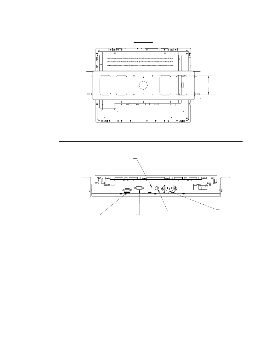
Rear View
r
Side View
75
75
Power
switch
Touch interface
serial
2-6 Elo Entuitive Touchmonitor User Guide
Video cable
connector
Remote OSD
connector
Power
connecto
Page 13
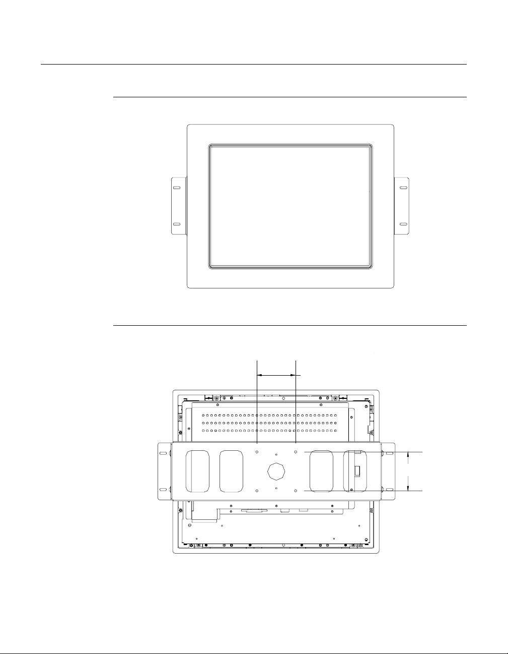
Prod uct O verview (1567L)
Main Unit
Rear View
75
75
2-7
Page 14
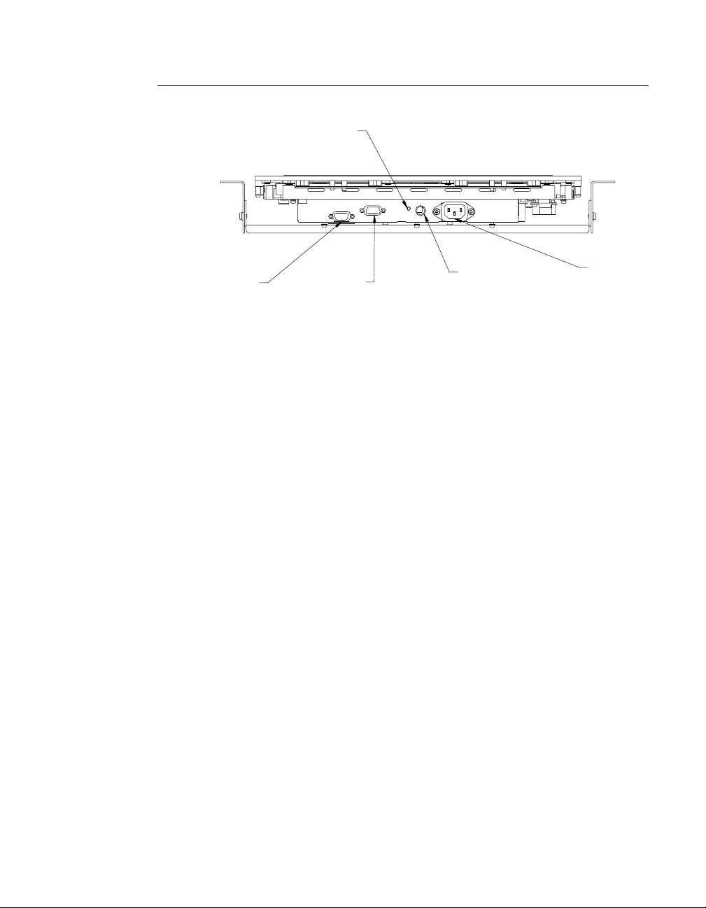
Side View
r
Power
switch
Touch interface
serial
Video cable
connector
Remote OSD
connector
Power
connecto
2-8 Elo Entuitive Touchmonitor User Guide
Page 15
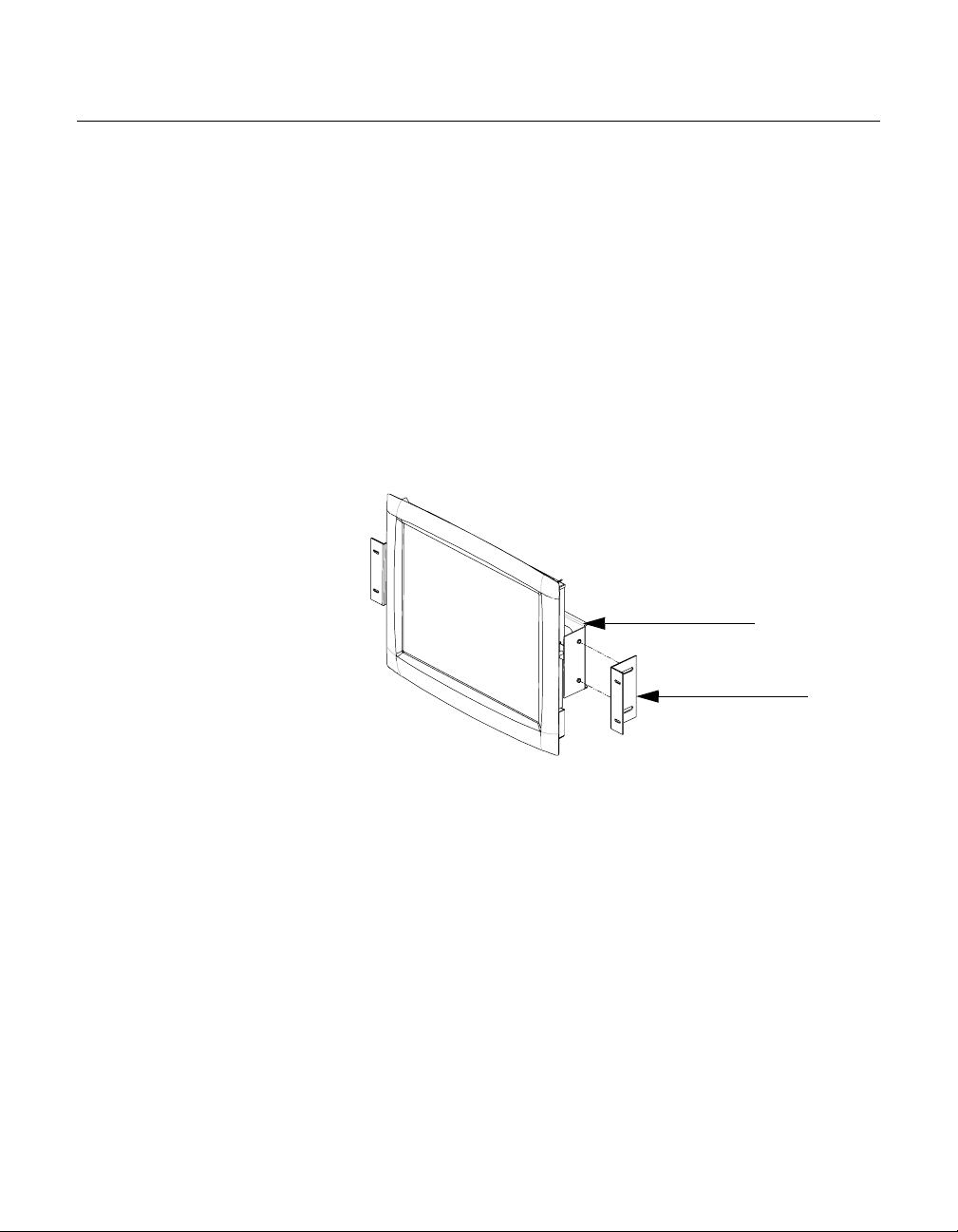
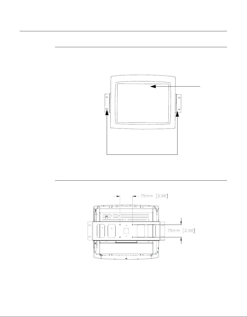
Attaching the L-Brackets
Depending on your mounting scheme, use the L-brackets or the VESA 75mm
standard holes lo cated on the back of the kiosk monitor. See page 15 for VESA
mounting information.
N
OTE
:
You will need a screwdriver to attach the L-brackets.
Your kiosk touchmonitor comes with a mounting bracket (C-bracket) attached
at the back. Included are two L-brackets (and four screws) that attach to both
ends of the C-bracket for additional mounting options.
To attach the L-bra ck ets :
1 Lay the monitor face down.
2 Place the long end of the L-bracket ag ain st the end of the mounting
C-bracket. Line up the two holes of the L-bracket with the two holes of the
C-bracket. See the illustration below.
C-bracket
L-bracket
3 Place two screws in the holes and with the screwdriver, screw them in to
secure the bracket.
4 Repeat steps 2 and 3 to attach the other L-bracket to the other side of the
mounting bracket.
2-9
Page 16
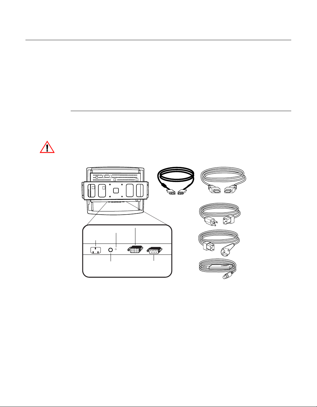
Touch Interface Con nection
N
OTE
:
Your interface cables may have been pre-connected to your monitor at the factory.
Your touchmonitor comes with one of the following touchscreen connector
cables: Serial (RS-232) cable or USB cable (For Windows 98 or Windows
2000 computers only.)
To setup this display, please refer to the following figures and procedur es:
Serial Connection
The following illust rations guide you step by step in connecting your
touchmonitor using a serial cable connection.
Before connecting the cables to your touchmonitor and PC, be sure that the computer
and the touchmonitor are turned off.
Video cable
Serial touchscreen
cable
Monitor power cable
(US/Canada)
Power Switch
Power
OSD Remote
port
Connections on underside
Female
video
connector
Female serial
touchscreen
connector
2-10 Elo Entuitive Touchmonitor User Guide
European monitor
power cable
OSD Remote
Page 17
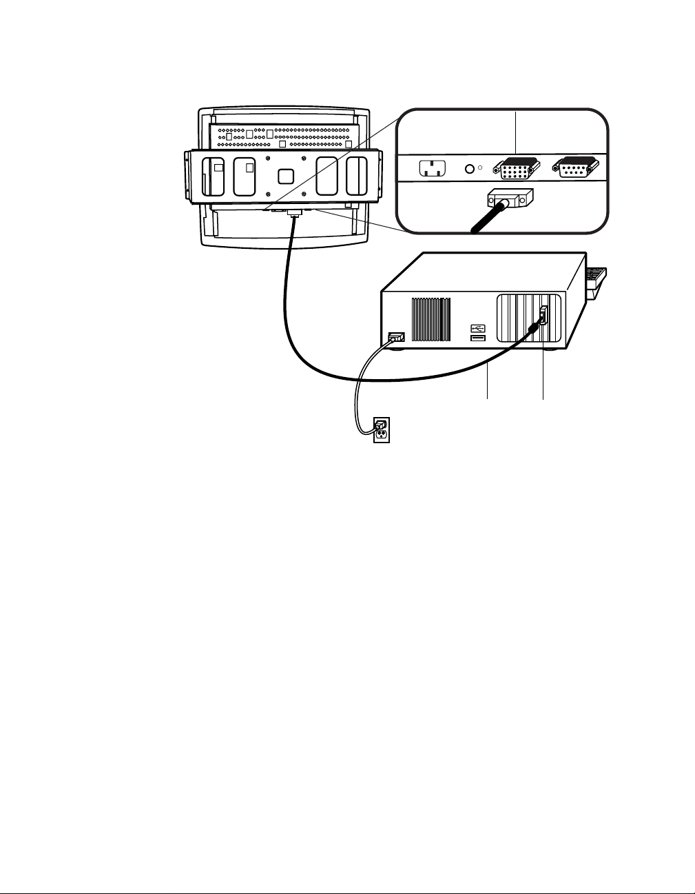
Connecting the V ideo Cable
Connections on underside
Female 15-pin
video
connector
Video
cable
Video
port
• Connect the 15-pin video cable to the video port on your PC.
• Connect the other end of the video cable to the video connector on your
touchmonitor.
• Secure the cable to your touchmon itor and PC by turning the screws on the
connector clockwi se.
2-11
Page 18

Connecting the Serial Touchscreen Cable
Connections on underside
Serial
touchscreen
cable
Serial
touchscreen
cable
• Connect the female end of the serial (RS-232) cable to the serial port on the
back of your PC.
• Connect the male e nd of th e cable to t he s erial t ouchsc reen conne ctor on your
touchmonitor.
• Secure the cable to your touchmon itor and PC by turning the screws on the
connector.
2-12 Elo Entuitive Touchmonitor User Guide
Page 19
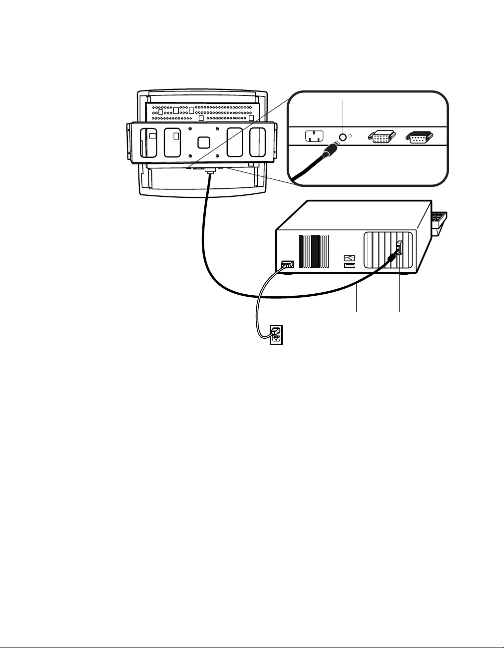
Connec t th e Remote OSD Cable
Connections on underside
OSD
remote
port
Video
cable
Video
port
Ferrite bead
• Connect the 6 pin DIN cable to the OSD Remote port on your touchmonitor.
2-13
Page 20

Connecting the Power Cable
Connections on underside
Power Cable
Power cable
Depending on where you live, you will use either the European or US/Canadian
power cable.
• Connect the female end of the power cable into the power port on the
touchmonitor.
N
OTE
:
To protect your equipment against risk of damage from electrical surges in the power
line, plug the touchmonitor’s power cor d int o a surge protector, and then connect the
surge protector to a grounded (three-pronged) AC electrical outlet.
• Power on your PC then your touchmonitor. After a brief pause the picture
should appear.
2-14 Elo Entuitive Touchmonitor User Guide
Page 21

N
USB Connection
OTE
:
A USB connection can only be used if your PC is running Windo ws 98 or Windows 2000.
The following illust rations guide you step by step in connecting your
touchmonitor using a USB cable connection.
Before connecting the cables to your touchmonitor and PC, be sure that the computer
and the touchmonitor are turned off.
USB touchscreen
cable
Power
Connections on underside
OSD
Remote
port
Power
switch
USB
port
Female 15-pin
video
connector
Video cable
Monitor
power cable
(US/Canada)
European
power cable
OSD Remote
2-15
Page 22

Connecting the V ideo Cable
Connections on underside
Female 15-pin
video
connector
Video
cable
Video
port
• Connect the 15-pin video cable to the video port on your PC.
• Connect the other end of the video cable to the video connector on your
touchmonitor.
• Secure the cable to your touchmon itor and PC by turning the screws on the
connector clockwi se.
2-16 Elo Entuitive Touchmonitor User Guide
Page 23

Connecting the USB Touchscreen Cable
Connections on underside
USB
touchscreen
connector
USB
touchscreen
cable
• Connect the USB t ouchscree n cabl e to the US B touch screen co nnector on the
touchmonitor.
• Connect the other end of the USB cable to your PC.
• The touchscreen cabl e connector s should fit snugly into the connectors on
your touchmonitor and PC.
2-17
Page 24

Connecting the R em ote OSD Cable
Connections on underside
OSD
Remote
Port
Video
cable
Ferrite bead
Video
port
• Connect the 6 pin DIN cable to the OSD Remote port on your touchmonitor.
2-18 Elo Entuitive Touchmonitor User Guide
Page 25

Connecting the Power Cable
Connections on underside
Power Cable
Power cable
Depending on where you live, you will use either the European or US/Canadian
power cable.
N
• Connect the female end of the power cable into the power port on the
touchmonitor.
OTE
:
To protect your equipment against risk of damage from electrical surges in the power
line, plug the touchmonitor’s power cor d int o a surge protector, and then connect the
surge protector to a grounded (three-pronged) AC electrical outlet.
• Power on your PC then your touchmonitor. After a brief pause the picture
should appear.
2-19
Page 26

Optimizing the LCD Display
To ensure the LCD display works well with your compute r, configure the
display mode of your graphic card to make it less than or equal to 1024 x 768
resolution, and make sure the timing of the display mode is compatible with the
LCD display. Refer to Appendix A for more information about resolution.
Compatible video modes for your touchmonitor are listed in Appendix C.
VESA M ou nt on Your Touchmon itor
Your kiosk touchmonitor comes with a VESA standard mounting bracket (C
bracket) attached at the back. Included are two sliders (L brackets) that attach to
both ends of the C bracket for additional mounting options. Your touchmonitor
conforms to the VESA Flat Panel Monitor Physi cal Mounting Interface
(FPMPMI™) Standard which defines a physi cal mounting interface for flat
panel monitors, and corresponding standards for flat panel monitor mounting
devices, such as wal l and ta ble arm s .
The following companies provide VESA mounting devices compatible with
your touchmonitor:
Ergotron
800-888-8458
651-681-7600
www.ergotron.com
GCX
800-228-2555
707-773-1100
www.gcx.com
2-20 Elo Entuitive Touchmonitor User Guide
Innovative Office Pro ducts
800-524-2744
610-253-9554
www.innov-office-prod.com
MRI
800-688-2414
www.mediarecovery.com
Page 27

Installing the D river Soft ware
Elo TouchSystems provides driver software that allows your touchmonitor to
work with your computer. Drivers a re located on the enclosed CD-ROM for the
following operat ing systems:
• Windows XP
• Windows 2000
• Windows Me
• Windows 98
• Windows 95
• Windows NT 4.0
Additional driver s and driver information fo r other operating systems (i ncluding
MS DOS, Windows 3.x, OS/2, Macintosh and Linux) are available on the Elo
TouchSystems web site at www.elotouch.com.
Your Elo touchmonitor is plug-a nd-play compliant. Informati on on the video
capabilitie s of your touchmonitor is sent to your video display adapte r when
Windows starts. If Windows detects your touchmonitor, follow the instr uctions
on the screen to install a generic plug-and-play monitor.
Refer to the appropriat e following section for driver instal lation instructions.
2-21
Page 28

N
Installing the Serial Touch Driver for Windows XP, Windows 20001, Me, 95/98 and NT 4.0
OTE
:
For Windows 2000 and NT 4.0 you must have administrator access rights to install the
driver.
1 Insert the Elo CD-ROM in your computer’s CD-ROM drive.
If the AutoStart feature for your CD-ROM drive is active, the system
automatically de tects the CD and starts the setup program.
2 Follow the directions on the screen to complete the driver setup for your
version of Windows.
If the AutoStart featu re is no t acti ve:
1 Click Start > Run.
2 Click the Browse button to locate the EloCd.exe program on the CD-ROM.
3 Click Open, then OK to run EloCd.exe.
4 Follow the directions on the screen to complete the driver setup for your
version of Windows.
1.To install Windows 2000 and Windows XP, you must use the "update driver"
method; you will not find a setup.exe fil e within the download.
2-22 Elo Entuitive Touchmonitor User Guide
Page 29

Inst a lling the Serial Touch Driver for M S-DOS and Windows 3. 1
To install Windows 3.x and MS-DOS from Windows 95/98, follow the
dire c t io ns below:
1 Insert the Elo CD-ROM in your computer’s CD-ROM drive.
2 From DOS, type d:\EloDos_W31 to change to the correct directory on the
CD-ROM (your CD-ROM drive may be mapped to a different drive letter).
3 Type install and press Enter to start the installation.
4 Align the touchscree n.
You must have already completed Steps 1 and 2 before proceeding. Refer to
Chapter 2 of the Elo DOS and Windows Driver Guide as necessary for
additional ins tallation information.
To run the INSTALL program:
1 Type INSTALL at the DOS prompt in the directory containing the driver
inst a l l f i l e s .
2 INSTALL asks you to select the softwar e to install. Then choose
d:\EloDos_W31 from the displ ayed list.
3 INSTALL also asks you for the paths to use during ins tallation, or you may
use its defaults. INSTALL creates directories as necessary, and warns you if
they exist.
If you are updating your softwar e, you may wish to specify the paths conta ining
the earlier versi ons, and overwrite the obsolete files. All ex ecutable programs
are upward comp a tib le. Fo r a list of differences from each pre viou s ve rs ion of
the drivers, be sure to select "Differences from Previous Versions" during the
installation process.
INSTALL updates your AUTOEXEC.BAT file with the drivers you select.
INSTALL makes a copy of your original AUTOEXEC.BAT file, cal led
AUTOEXEC.OLD. If you already have Elo driver commands in your
AUTOEXEC.BAT file, they will be commented out.
When INSTALL is finished, it leaves a file called GO.BAT in the subdirectory
you specified. GO loads the touchscreen driver, runs the calibration program
ELOCALIB, and gives you some final instructions.
If you are using Windows 3.1, you will also align the touchscreen within
Windows 3.1 with the Touchscreen Control Panel.
2-23
Page 30

N
Installing the USB T ouch Driver
Inst alling t he U SB Touch Dr iver for W indo ws 98 a nd Wi ndo ws
2000
1 Insert the Elo CD-ROM in your computer’s CD-ROM drive.
If Windows 98 or Windows 2000 starts the Add New Hardware Wizard:
2 Choose Next. Select “Search for the best driver for your device
(Recommended)” and choose Next.
3 When a list of search locations is displayed, place a checkmark on “Specify a
location” and use Browse to select the \EloUSB directory on the Elo
CD-ROM.
4 Choose Next. Once the El o TouchSystems USB touchscreen driver has been
detected, choose Next again.
5 You will see several files being copied. Insert your Windows 98 CD if
prompted. Choose Finish.
If Windows 98 or Windows 2000 does not start the Add New Hardware Wizard:
OTE
:
For Win dows 2000 you must have administr ator access rights to inst all the driver.
1 Insert the Elo CD-ROM in your computer’s CD-ROM drive.
If the AutoStart feature for your CD-ROM drive is active, the system
automatically de tects the CD and starts the setup program.
2 Follow the directions on the screen to complete the driver setup for your
version of Windows.
If the AutoStart featu re is no t acti ve:
1 Click Start > Run.
2 Click the Browse button to locate the EloCd.exe program on the CD-ROM.
3 Click Open, then OK to run EloCd.exe.
4 Follow the directions on the screen to complete the driver setup for your
version of Windows.
2-24 Elo Entuitive Touchmonitor User Guide
Page 31

About T ouchmonitor Adjustments
Your touchmonitor will likely require adjustment. Variations in video output
and application will require you to adjust your touchmonitor to optimize the
quality of the displa y.
For best performance, your monitor should be operating in native resolution,
that is 1024 x 768 at 60-75 Hz. Use the Display control panel in Windows to
choose 1024 x 768 resolution.
C HAPTER
3
C
HAPTER
3
O
PERATION
Operating in other resolutions will degrade video performanc e . For further
information, please refer to Appendix A.
All adjustments you make to the controls are automatically memorized. This
feature saves you from having to rese t your choices every time you unplug or
power your touchmonitor off and on. If there is a power failure your
touchmonitor settings will not default to the factory specifications.
Using the On-Scr een Display M enus
All adjustments are made by using the on-screen display (OSD) menus. All
menu items can be selected by using the buttons on the side bezel.
N
OTE
:
OSD menu default is enabled. Press the UP and DO WN b uttons at the same time to
enable/disable the OSD funct ions
3-25
Page 32

Remote OSD Buttons
AUTO/SEL DOWN UP MENU
AUTO/SEL DOWN UP MENU
1
MENU
UP
2
3
DOWN
4
AUTO/SEL
5
1
2
3
4
Control Function
Menu
Contrast/
Plus/Clockwise
Brightness/Minus/
Counter-Clockwise
Auto/Select
Power Switch Switches on/off the power of your touchmonitor.
Enable/Disable
Display Exits the OSD menus.
1. Enter contrast of the OSD
2. Increase value of the adjustment item.
3. Select item clockwise
1. Enter brightness of the OSD
2. Decrease value of the adjustment item
3. Select item counter-clockwise
Select- To select the adjustment items from the
OSD menus.
Auto- To activate the “Auto Adjustment”
function to obtain an optimum image.
1. Press the Menu and Up buttons at the same
time and hold for two seconds to enable/disable
the OSD functions. OSD menu default is
enabled.
2. Press the Menu and Down buttons at the same
time to enable/disable the power lock function.
5
3-26 Elo Entuitive Touchmonitor User Guide
Page 33

OSD M enu F unction
CONTRAST
50
Contrast
Controls the picture contrast
Brightness
Controls the picture brightness
V-Position
Controls the vertical position
H-Position
Controls the horizonta l position
Recall De faults
Recalls f actory sett ings of the image
parameters
C1/C2/USER (Color)
Using these icons, you can se lect one of
the preset color temperatures (9300°K or
6500°K). Confirm your ch oice by
pres si ng the SELECT button. If you
want to change the color temperatures
individually, select USER and confirm by
pressing the OSD button SELECT. Now
you can use the OSD dial to toggle
between the settings R, G and B (red,
green and bl ue foreground). To change a
setting, first press the SELECT button,
then ch oo s e the desir ed valu e w ith the
OSD dial. To confirm the setting, press
the SELECT button again.
If you don’t need to adjust an y further
settings, choose the
icon to return to the OSD main menu.
Phase
Controls the vertical fine adjustment
Clock
Controls the horizontal fine adjustme nt
OSD H-Position
Adjusts the horizontal position of the OSD
menu
OSD V-Position
Adjust th e vertical position of the OSD men u
OSD Time
Determines how long (in seconds) the OSD
menu waits before closing au to m a tically af te r
no action has been performed.
Auto Adjus t
Autom at ic a lly selects th e o pt io n al settings for
image parameters (brightness, contrast, image
position, phase, etc.)
OSD Language
Selection of the OSD menu langu age: English,
French, Italian, Sp anish, Japanese.
Image Information
Display s the current graphics mode.
3-27
Page 34

3-28 Elo Entuitive Touchmonitor User Guide
Page 35

If you are experiencing trouble with your touchmonitor, refer to the following
table. If the problem persists, please contact your local dealer or our service
center.
Solutions to Common Problems
C HAPTER
4
C
HAPTER
4
T
ROUBLESHOOTING
Problem Suggestion(s)
No image ap pears on screen . Check that al l the I/O and power connector s are properly
connected as described in Chapter 2.
Make sure the pins of the connectors are not crooked or
broken.
Test power su pply by trying different cables, a differe n t
wall outlet or plug another appliance into the outlet.
Make certa in the vi deo cab le is prope rl y conne ct ed a nd tha t
it is not damaged. Check for bent pins on the cable
connectors.
Ensure that your computer and video card ar e properly
configured. (Consult video card documen tation.)
“Out of Range ” display Check to see if the resolution of your computer is higher
than that of the LCD display.
Reconfigure the resolution of your computer to make it less
than or equal to 1024 x 768. See A ppendix A for more
info rmation on r es o lu ti on.
4-29
Page 36

Image has vertical flickering lin e bars. Use “PHASE” to make an adju stment.
Check and reco nfigure the display mode of the vertical
refresh ra te of y our gr aph ic car d t o mak e it co mpat ib le with
the LCD display.
Image is uns table and flickering Use “CLOC K” to m ake an adjustme nt.
Image is scrolling Make sure the VGA signal cable (or adapter) is well
connected.
Check and reco nfigure the display mode of the vertical
refresh ra te of y our gr aph ic car d t o mak e it co mpat ib le with
the LCD display.
Touch doesn’t work Make sure cable is secure ly attached at both ends.
4-30 Elo Entuitive Touchmonitor User Guide
Page 37

A PPENDIX
A
C
HAPTER
4
N
ATIVE
The native resolution of a monitor is the resolution level at which the LCD
panel is designed to perfor m best. For the Elo LCD touchmonitor, the native
resolution is 1024 x 768 for the XGA-15 inch siz e. In almost all cases, screen
images look best when viewed at their native resolution. You can lower the
resolution setting of a monitor but not increase it.
Input Video 15” LCD
640x480 (VGA) Transforms i nput format to 1024x7 68
800x600 (SVGA) Transforms i nput format to 1024x7 68
1024x768 (XGA) Displays in Native Resoluti on
R
ESOLUTION
The native resolution of an LCD is the actual number of pixels horizontally in
the LCD by the number of pixels vertical ly in the LCD. LCD resol ution is
usually represented by the following symbols:
VGA
SVGA
XGA
SXGA
UXGA
640x480
800x600
1024x768
1280x1024
1600x1200
A-31
Page 38

As an example, a SVGA resolution LCD panel has 800 pixels horizontally by
600 pixels vertically. Input video is also represented by the same terms. XGA
input video has a format of 1024 pixels hor iz ontally by 768 pixels vertically.
When the input pixels containe d in the video input format match the native
resolution of the pa nel, there i s a one to one corre spondence of mapping of input
video pixels to LCD pixels. As an example, the pixel in 45 column and 26 row
of the input video is in 45 column and 26 row of the LCD. For the case when
the input vide o is a t a lowe r res oluti on than t he nat ive res oluti on of th e LCD, the
direct corresponde nce between the video pixels and the LCD pixels is lost. The
LCD controller c an compu te the correspon dence be tween video pi xels a nd LCD
pixels using algorithms contained in the controller. The accura cy of the
algorithms determines the fidelity of conversion of video pixels to LCD pixels.
Poor fideli ty conversion can result in artifacts in the LCD displayed image such
as varying width charact ers.
A-32 Elo Entuitive Touchmonitor User Guide
Page 39

A PPENDIX
B
C
HAPTER
4
T
OUCHMONITOR
This manual contains inf ormation that is important for the proper setup and
maintenance of your touc hmonitor. Befor e setti ng u p and poweri ng on your new
touchmonitor, read thr ough this manual, especia lly Chapter 2 (Insta llati on), and
Chapter 3 (Ope rati o n).
1 To reduce the risk of electric shock, follow all safety notices and never open
the touchmonitor case.
2 Turn off the product before cleaning
S
AFE TY
3 Your new touchmonitor is equipped with a 3-wire, grounding power cord.
The power cord plug will onl y fit into a grounde d outlet. Do not a ttempt to fit
the plug into an outlet that has not been confi gured for this purpose. Do not
use a damaged power cord. Use only the power cord that comes with your
Elo TouchSystems Touchmonitor. Use of an unauthorized power cord may
invalidate your warranty.
4 The slots located on the sides and top of the touchmo nitor case are for
ventilatio n. Do not bloc k or insert anything inside the ventilation slots.
5 It is important that your touchmonitor remains dry. Do not pour liquid int o or
onto your touchmonitor . If your touchmo nitor becomes wet do not attempt to
repair it yourself.
B-33
Page 40

Care an d Handling of Your Touchm onitor
The following tips will help keep your Elo Entuitive touchmonitor functioning
at the optimal level.
• To avoid risk of electric shock, do not disassemble the brick supply or
display unit cabine t. The unit is not user serviceable. Remember to unplug
the display unit from the power outlet before cleaning.
• Do not use alcohol (methyl, ethyl or isopropyl) or any strong dissolvent. Do
not use thinner or benzene, abra sive cleaners or compressed air.
• To clean the display unit cabinet , use a cloth lightly dampened with a mild
detergent.
• Avoid getting liquids inside your touchmonitor. If liquid does get inside,
have a qualified servi ce te chnician check it before you power it on again.
• Do not wipe the screen with a cloth or sponge that could scratch the surface.
• To clean the touchscreen, use window or glass cleaner. P ut the cleaner on the
rag and wipe the touchscreen . Never apply the cleaner directly on the
touchscreen.
B-34 Elo Entuitive Touchmonitor User Guide
Page 41

Com patibility Modes
Your Elo Entuiti ve touc hmonitor is c ompati ble with the f ollowing vi de o modes:
Mode Resolution H. Frequency (kHz) V. Frequency (Hz)
IBM & VESA VGA 640 x 350 31.47 70.09
IBM & VESA VGA 640 x 400 31.47 70.09
IBM & VESA VGA 720 x 400 31.47 70.09
IBM & VESA VGA 640 x 480 31.47 59.94
IBM & VESA VGA 640 x 480 37.86 72.81
IBM & VESA VGA 640 x 480 37.50 75.00
VESA VGA 800 x 600 35.16 56.25
VESA VGA 800 x 600 37.88 60.32
VESA VGA 800 x 600 48.08 72.19
VESA VGA 800 x 600 46.88 75.00
VESA VGA 800 x 600 48.36 60.00
VESA VGA 800 x 600 56.48 70.07
VESA VGA 800 x 600 60.02 75.03
Apple Macintosh LC 13” 640 x 480 34.97 66.61
Apple Macintosh II 13” 640 x 480 35.00 66.67
Apple Macintosh 16” 832 x 624 49.73 74.55
Apple Macintosh 19” 1024 x 768 60.24 75.02
NEC FC-98 series 640 x 400 31.47 70.01
NEC FC-98 series 640 x 480 31.47 59.94
C
HAPTER
4
T
ECHNICAL
A PPENDIX
C
S
PECIFICATIONS
C-35
Page 42

Touchmo nitor Specifications ET1545L/1 547L/1548L/156 7L
Table C.1
15" LCD Touchmonitor Specifications
Display Type
Size
Pixel Format
Touchscreen
Colors
Display
Active matrix, thin film transistor
(TFT) , liquid cry stal display
15-inch diagonal
304 x 228 mm useful screen area
1024 x 768
0.125-inch IntelliTouch and
SecureTo uch, anti-glare
Surface wave technology
16 million with dithering
IntelliTouch: 270 cd/m² Max. AccuTouch: 252 cd/m² Max.
Brightness
Back-light Lamp
Life
Viewing Ang le
Contrast Ratio
Display R esponse
40,000 hou rs at full brightness
typical
Horizontal
Vertical
450:1 typical
13 ms(tr)/27 ms(tr)
Time
Operating Temp
Storage Temp
Environmental
Mechanical
Electrical
Humidity
Weight
Size
Input Video
Input Power
Power Dissipation
Safety & EMC UL, cUL and TUV
Agencies
SecureTouch: 252 cd/m ² Max.
-75~75 or 150 degrees total
-70~70 or 140 degrees total
0°C to 50°C
-30°C to +60°C
80% non-cond ensing
10.6 lbs. maximum approx.
weight for IntelliTouch and
SecureTouch
See drawi ngs on pag es 40,41, an d
43.
VGA/SVGA/XGA analog video
100-240 VAC, 50/60 Hz.
Universal
FCC-B, CE, C-Tick, MRPII and
VCCI
C-36 Elo Entuitive Touchmonitor User Guide
Page 43

Touchmo nitor Specifications ET1549L
Table C.2
15" LCD Touchmonitor Specifications
Display Type
Size
Pixel Format
Touchscreen
Colors
Display
Active matrix, thin film transistor
(TFT) , liquid cry stal display
15-inch diagonal
308 x 232 mm useful screen area
1024 x 768
0.125-inch IntelliTouch
Surface wave technology
262,144
IntelliTouch: 225 cd/m² Max.
Brightness
Back-light Lamp
Life
Viewing Ang le
Contrast Ratio
Display R esponse
50,000 hou rs at full brightness
typical
Horizontal
Vertical
400:1 typical
15 ms(tr)/10 ms(TF)
Time
Operating Temp
Storage Temp
Environmental
Mechanical
Electrical
Humidity
Weight
Size
Input Video
Input Power
Power Dissipation
Safety & EMC UL, cUL and TUV
Agencies
±80 or 16 0 de grees total
±80 or 16 0 de grees total
0°C to 50°C
-30°C to +60°C
80% non-cond ensing
10.6 lbs. maximum approx.
weight for IntelliTouch and
SecureTouch
See drawings on pages 41.
VGA/SVGA/XGA analog video
100-240 VAC, 50/60 Hz.
Universal
FCC-B, CE, C-Tick, MRPII and
VCCI
C-37
Page 44

Table C.3
IntelliTouch Touchmonitor Specification s
Mechanical
Positional Accuracy
Touchpoint Density
Touch Activation
Standard deviation of error is less than 0.080 in. (2.03 mm ).
Equate s to les s th an ± 1%.
More than 100,000 touchpoints/in2 (15,500 touchpoints/cm2).
Typically less than 3 ounces (85 grams).
Force
Surface Durability
Expected Life
Performance
Sealin g
Surfac e durability is that of glass, Mohs’ hardne ss rating of 7.
No know n we ar -o ut mechan ism, as th er e are no laye rs , co atings,
or moving pa rts. IntelliTouch technology has been operationall y
tested to more than 50 million touches in one location wit h out
failure, using a stylus similar to a finger.
Unit i s sealed to protect a gainst s plashed li quids, dir t, and dust .
See IntelliTouch Ultra Product Manual for details.
Optical
Light Transmission
92%
(per ASTM D1003)
Visual Resolution
Gloss (per ASTM
D2457 using a 60degree gloss meter)
All measurem ents made using U SA F 1951 Resolution Chart,
under 30X magnification, with test uni t located approximately
1.5 in (38 mm) from surface of resolution chart.
Clear surface: Excellent, wit h no noticeable degradation.
Antiglare surface: 6:1 minimum.
Clear surface: N/A
Antiglare surface: Curved: 60 ± 20 gloss units or 75 ± 15 gloss
units.
Environmental
Chemical Resistance
Electrostatic
The acti ve area of the touchscreen is resistant to all che micals
that do no t affect glas s, such as:
Acetone
Toluene
Methyl et hyl ketone
Isopropyl alcohol
Methyl alcohol
Ethyl ac etate
Ammo ni a-based glass clea ners
Gasoline
Kerosene
Vinegar
Meets Level 4 (15 kV air/8 kV contact discharges).
Protection (per
EN 61 000-4- 2, 1995)
C-38 Elo Entuitive Touchmonitor User Guide
Page 45

Table C.4
SecureTouch Touchmonitor Specifications
Mechanical
Positional Accuracy
Touchpoint Density
Touch Activation
Standard deviation of error is less tha n 0.080 in. (2.03 mm ).
Equate s to les s th an ± 1%.
More than 100,000 touchpoints/in2 (15,500 touchpoints/cm2).
Typically less than 3 ounces (85 grams).
Force
Surface Durability
Expected Life
Performance
Surfac e durability is that of glass, Mohs’ hardne ss rating of 7.
No know n we ar -o ut mechan ism, as th er e are no laye rs , co atings,
or moving pa rts. IntelliTouch technology has been operationall y
tested to more than 50 million touches in one location wit h out
failure, using a stylus similar to a finger.
Optical
Light Transmission
92%
(per ASTM D1003)
Visual Resolution
Gloss (per ASTM
D2457 using a 60degree gloss meter)
All measurem ents made using U SA F 1951 Resolution Chart,
under 30X magnification, with test uni t located approximately
1.5 in (38 mm) from surface of resolution chart.
Clear surface: Excellent, wit h no noticeable degradation.
Antiglare surface: 6:1 minimum.
Clear surface: N/A
Antiglare surface: Curved: 60 ± 20 gloss units or 75 ± 15 gloss
units.
Environmental
Chemical Resistance
Electrostatic
The acti ve area of the touchscreen is resistant to all che micals
that do no t affect glas s, such as:
Acetone
Toluene
Methyl et hyl ketone
Isopropyl alcohol
Methyl alcohol
Ethyl ac etate
Ammo ni a-based glass clea ners
Gasoline
Kerosene
Vinegar
Meets Level 4 (15 kV air/8 kV contact discharges).
Protection (per EN 61
000-4-2, 1995)
C-39
Page 46

15" LCD Touchm onitor Dimen sions
ET1545L
C-40 Elo Entuitive Touchmonitor User Guide
Page 47

See www.elotouch.com/ pdfs/drawings/ms500235.pd f
ET1547L/1548L/1549L
296
313
9
305
229
380
430
4.3
R5.4
110
237
C-41
Page 48

See detail A
A=28
1
Detail A
Scale 2:1
90
115
65
460
380
75
70
56
C-42 Elo Entuitive Touchmonitor User Guide
77
75
296
Page 49

ET1567L
400
305
4.3
316
70
430
229
9
66
30
C-43
Page 50

75
75
65
Cut Out Dimensions
ET1545L Front Mount Cut Out
86
See www.elotouch.com /pdfs/drawings/ms500 108.pdf for more information.
C-44 Elo Entuitive Touchmonitor User Guide
Page 51

ET1545L Rear Mount Cut Out
ET1547L/1548L/1549L Rear Mou nt Plate C ut Out
157
4X Customer Option
See notes
NOTES:
Material:
1. Wood: 04.5 holes thru for M4 screws w/nuts
or screws for wood 04 mm.
2. Sheet Metal: Concealed head threaded studs
M4 w/nuts.
314.0 +1.0
0
440
4X R4.00
119
70
238.0 +1.0
0
C-45
Page 52

ET1567L Fr ont M ount Pl ate C ut Out
314.0 +1.0
0
157
4X Customer Option
See notes
440
NOTES:
Material:
1. Wood: 04.5 holes thru for M4 screws w/nuts
or screws for wood 04 mm.
2. Sheet Metal: Concealed head threaded studs
M4 w/nuts.
4X R4.00
119
70
238.0 +1.0
0
C-46 Elo Entuitive Touchmonitor User Guide
Page 53

C
HAPTER
4
R
EGULATORY INFORMATION
I. Electrical Safety Information:
A) Compliance is required with respect to the voltage, frequency, and current
requirements indicated on the manufacturer’s label. Connection to a different
power source than those specified herein will likely result in improper operation,
damage to the equipment or pose a fire hazar d if the limitations are not followed.
B) There are no operator serviceable parts ins ide this equipment. There are ha zardous vol tages generated by this equipment which constitute a safety hazard. Se rvice
should be provided only by a qualified service technician.
C) This equipment is pro vided with a detachable power cord which has an integr al
safety ground wire and 3-prong connector intended for connection to a grounded
safety outlet.
1) Do not substi tute the cord with othe r than the provided approved type .
Under no circumstances use an adapter plug to connect to a 2-wire outlet as
this will defeat the continuity of the grounding wire.
2) The equipment requires the use of the ground wire as a part of the safety
certification, modification or misuse can provide a shock hazard that can
result in serious injury or death.
3) Contact a qualified electrician or the manufacturer if there are questions
about the installation prior to conn ecting the equ ipment t o mains power.
II. Emissions and Immunity Informati on
A) Notice to Users in the United States: This equipment has been tested and found
to comply with the limits for a Class B digital device, pursuant to Part 15 of FCC
Rules. These limits are designed to provide reasonable protection against harmful
interference in a residential installation. This equipment generates, uses, and can
radiate radio frequency ener gy, and if not installed and used in accordance with the
instructions, ma y cause harmfu l interfer ence to radio communications.
B) Noti ce to User s in Canada: This equipmen t complies with the Class B limits for
radio noise emissions from digital apparatus as established by the Radio Interference Regulations of Industrie Canada.
C) Notic e to U se rs in th e E ur o pe an Union: Us e on ly th e pr ov id ed pow e r co rd s and
interconnecting cabling provided with the equipment. Substitution of provided
cords and cabling may compromise electrical safety or CE Mark Certification for
emission s or immunity as required by the followi ng standards :
This Inform ation T echnology Equipment (ITE) is require d to have a CE Mark
on the manufacturer’s label which means that the equipment has been tested
to the following Directives and Standards:
47
Page 54

This equipment has been tested to the requirements for the CE Mark as
required by EMC Directive 89/336/EEC indicated in European Standard EN
55 022 Class B and the Low Voltage Directive 73/23/EEC as indicated in
European Standard EN 60 950.
D) General Information to all Users: This equipment generates, uses and can radiate radio frequency energy. If not installed and used according to this manual the
equipment may cause interference with radio and television communications.
There is, however, no guarantee that interference will not occur in any particular
instal lation due to site-specific fa ctors.
1) In order to meet emission and immunity requirements, the user must
observe the following:
a) Use only the provided I/O cables to connect this digital device with
any computer.
b) To ensure compliance, use only the provi d ed m anufactu rer’s approved
line cord.
c) The user is cautioned that changes or modifications to the equipment
not expressly approved by the party responsible for compliance could
void the user’s authority to operate the equipment.
2) If this e quipment ap pears to cau se interfe rence with r adio or tel evision
reception, or any other device:
a) Verify as an emission sou rce by turning the equipment off and on.
b) If you de te r m in e th a t th is equ i pm e n t is cau s in g the int er fe rence, try to
correct the interference by using on e or m o re of the following measures:
i) Move the digital device away from the affected receiver.
ii) Reposition (turn) the digital device with respect to the affected
receiver.
iii) Reorient the affected receiv er’s antenna.
iv) Plug the digital device into a different AC outlet so the digital
device and the receiver are on different branch circuits.
v) Disconnect and remove any I/O cables that the digital device
does not use. (Unterminated I/O cables are a potential source of
high RF emission levels.)
vi) Plug the digital device into only a grounded outlet receptacle.
Do not u se AC adap ter plugs. (Re moving or cuttin g the line cord
ground may increase RF emission levels and may also present a
lethal shock hazard to the user.)
If you need additional help, consult your dealer, manufacturer, or an experienced radio or television technician.
48 Elo Entuitive Touchmonitor User Guide
Page 55

"The ap plicat ion of t his mo nitor i s restri cted to specia l cont rolled lumino us environments. The screen surface trend to reflec t annoying li ght of lamps and sunlight.
To avoid these reflections the monitor should not be positioned in front of a window or dir e ct ed to lumin a rie s. The mon i to r is in complian c e w ith Reflec tion Clas s
III acco rding to ISO 9241-7"
“Die Anwendung dieses Bildschirms ist auf speziel kontrollierte Umgebungsbeleuchtungen eingeschränkt. Die Bildschirmoberfläche neigt zu störenden Spielungen von Lampen und Sonnenlicht. Um diese Refelxionen zu vermeiden sollte
der Monitor nicht auf Fenster und Beleuchtungseinrichtungen ausgerichtet sein.
Der Monitor erfüllt nur die Relexionsklasse III nach ISO9241-7"
49
Page 56

50 Elo Entuitive Touchmonitor User Guide
Page 57

C
HAPTER
4
W
ARRANTY
Except as otherwise stated herein or in an order acknowledgment delivered to
Buyer, Seller warrants to Buyer that the Product shall be free of defects in
materials and workmanship. The warranty for the touchmonitors and
components of th e product are: 3 years monitor, 10 years IntelliTouch screen, 5
years Accu- Touch screen, 5 years Cont roller.
Seller makes no warranty regarding the model life of components. Seller’s
suppliers may at any time and from time to time make changes in the
components deliver ed as Products or components.
Buyer shall notify Seller in writing promptly (and in no case later than thirty
(30) days after discov ery) of the failure of any Product to conform to the
warranty set forth above; shall describe in commercially reasonable detail in
such notice the symptoms assoc iated with such failure; and shall provide to
Seller the opportun ity to inspect such Products as installed, if possible. The
notice must be received by Seller during the Warranty Period for such product,
unless otherwise directed in writing by the Seller. Within thirty (30) days after
submitting such noti ce, Bu yer shall package the allegedly defective Product in
its original ship ping carton(s) or a functional equivalent a nd shall ship to Seller
at Buyer’s expense and risk.
Within a reasonable time after receipt of the allegedly defective Product and
verification by Seller that the Product fai ls to meet the warranty set forth a bove ,
Seller shall corr ect such failure by, at Seller’s options, either (i) modifying or
repairing t he Product or (ii) replacing the Product. Such modific ation, repair, or
replacement and the return shipment of the Pro duct with minimum insurance to
Buyer shall be at Se ller’s expense. Buye r shall be ar the r isk of loss or damage in
transit, and may insure the Product. Buyer shall reimburse Seller for
transportat ion cost incurred for Product returned but not found by Selle r to be
defective. Modifi cati on or repair, of Products may, at Seller’ s option , take place
either at Seller ’s facilities or at Buyer’s premises. If Seller is unable to modify,
repair, or replace a Product to conform to the warranty set forth above, then
Seller shall, at Seller’s option, either refund to Buyer or credit to Buyer’s
account the purchase price of the Product less depreciation calculated on a
straight-line basis over Seller’s stated Warranty Period.
51
Page 58

THESE REMEDIES SHALL BE THE BUYER’S EXCLUSIVE REMEDIES
FOR BRE ACH OF WARRANTY. EXCE PT FOR THE EXPRESS
WARRANTY SET FORTH ABOVE, SELLER GRANTS NO OTHER
WARRANTIES, EXPRESS OR IMPLIED BY STATUTE OR OTHERWISE,
REGARDING THE PRODUCTS, THEIR FITNESS FOR ANY PURPOSE,
THEIR QUALITY, THEIR MERCHANTABILITY, THEIR
NONINFRINGEMENT, OR OTHERWISE. NO EMPLOYEE OF SELLER
OR ANY OTHER PARTY IS AUTHORIZED TO MAKE ANY WARRANTY
FOR THE GOODS OTHER THAN THE WARRANTY SET FORTH
HEREIN. SELLER’S LIABILITY UNDER THE WARRANTY SHALL BE
LIMITED TO A REFUND OF THE PURCHASE PRICE OF THE PR ODUCT.
IN NO EVENT SHALL SELLER BE LIABLE FOR THE COST OF
PROCUREMENT OR INSTALLATION OF SUBSTITUTE GOODS BY
BUYER OR FOR ANY SPECIAL, CONSEQUENTIAL, INDIRECT, OR
INCIDENTAL DAMAGES.
Buyer assumes the risk and agrees to indemnify Seller against and hold Seller
harmless from all liability relating to (i) assessing the suitability for Buyer’s
intended use of the Product s and of any system design or drawing and (ii)
determining the complia nce of Buyer’s use of the Products with applicable
laws, regulations, codes, and standards. Buyer retains and accepts full
responsibil ity for all warranty and other claims relatin g to or arising from
Buyer’s products, which include or incorporate Products or components
manufactured or supplied by Seller. Buyer is solely responsible for any and all
representations and warranties regarding the Products made or authorized by
Buyer. Buyer will indemnify Seller and hold Seller harmle ss from any liability,
claims, los s, cos t, or expe nses (inc lu ding rea sonable a tto rney’s fees) a ttribu table
to Buyer’s products or representations or warranties concerning same.
52 Elo Entuitive Touchmonitor User Guide
Page 59

Index
Numerics
15" LCD Tou c hm on it or Dim ensions, 40
15” LCD Touchmonitor (ET15-XXWC-1)
Spec ifications, 36, 37
A
About the Product, 1
About Touchmonitor Adjustments, 25
Attaching the L-Bra ck e ts, 9
Auto Adjust, 27
B
Bottom View/Side View (1545L), 5
Brightness, 27
C
C1/C 2/USER (Color), 27
Care and Handling of Your Touchmonitor, 34
Clock, 27
Compatibility Modes, 35
Connect the Remote OSD Cable, 13
Connecting th e Power Cable, 14, 19
Connecting the Remote OSD Cable, 18
Connecting the Serial Touchscr een Cable,12
Connecting the U SB Touchscr een Cable, 17
Connecting the Video Cable (Serial connect ion), 11
Connecting the Video Cable (USB connection), 16
Contrast, 27
Cut Out Dimension s , 44
E
ET1545L Dimensions, 40
ET1545L Front Mount Cut Out, 44
ET1545L Rear Mount Cut Out, 45
ET1547L/1548L/1549L Dimensions, 41
ET1547L/1548 L/1549L Rear Mount Plate Cut Out, 45
ET1567L Dimensions, 43
ET1567L Front Mount Plate Cut Out, 46
Image, unstable, 30
Image, vertical flickering, 30
Instal lation and S etu p, 3
Installing the Driver Software, 21
Installing the Serial Touch Driver for MS-DOS and
Windo ws 3.1, 23
Installing the Serial Touch Driver for Windows XP,
Windows 2000, Me, 95/98 and NT 4.0, 22
Insta lling the USB Touch D river, 24
Installing the USB Touch Driver for Windows 98 and
Windo ws 2000, 24
Intelli Touch Touc hm o nit or Spe c if i ca tio ns , 38
Introduction, 1
M
Main Unit (1 54 5L ) , 4
Main Unit (1 54 7L /1548L/15 49 L), 5
Main Unit (1 56 7L ) , 7
N
Native Resolution, 31
O
Operation, 25
Optimi zing the LCD Display,20
OSD H-Position, 27
OSD Lang uage, 27
OSD Menu Function, 27
OSD Time, 27
OSD V-Position, 27
Out of Range display, 29
P
Phase, 27
Precautions, 1
Product Overview (1545L), 4
Product Overview (1547L/1548L/1549L), 5
Product Overview (1567L), 7
H
H-Position, 27
I
Image Information, 27
Image problem, 29
Image, sc rolling, 3 0
R
Rear Vie w (154 5L), 4
Rear Vie w (154 7L/1548L /1549L), 6
Rear Vie w (156 7L), 7
Recall Defaults, 27
Regulatory Information, 47
Remote OSD Buttons, 26
Index-53
Page 60

S
SecureTouch Touchmonitor Specifications, 39
Serial Connection, 10
Side View (1547L/1548L/1549L ), 6
Side View (1567L), 8
Solutions to Common Problems, 29
Troubleshooting, 29
U
Unpacking Your Touchmonitor, 3
USB Connection,15
Using th e On-Screen Display Menus, 25
T
Technical Specifications, 35
Touch Interface Connection, 10
Touch not working, 30
Touchmonitor Safety, 33
Touchmonitor Specifications ET1545L/1547L/1548L/
1567L, 36
Touchmonitor Specifications ET1549L, 37
V
VESA Mount on Your Touchmon itor, 20
V-Position, 27
W
Warranty, 51
Index-54
Page 61

 Loading...