

Page 1
Serial interfaces to optic cable multiplexers
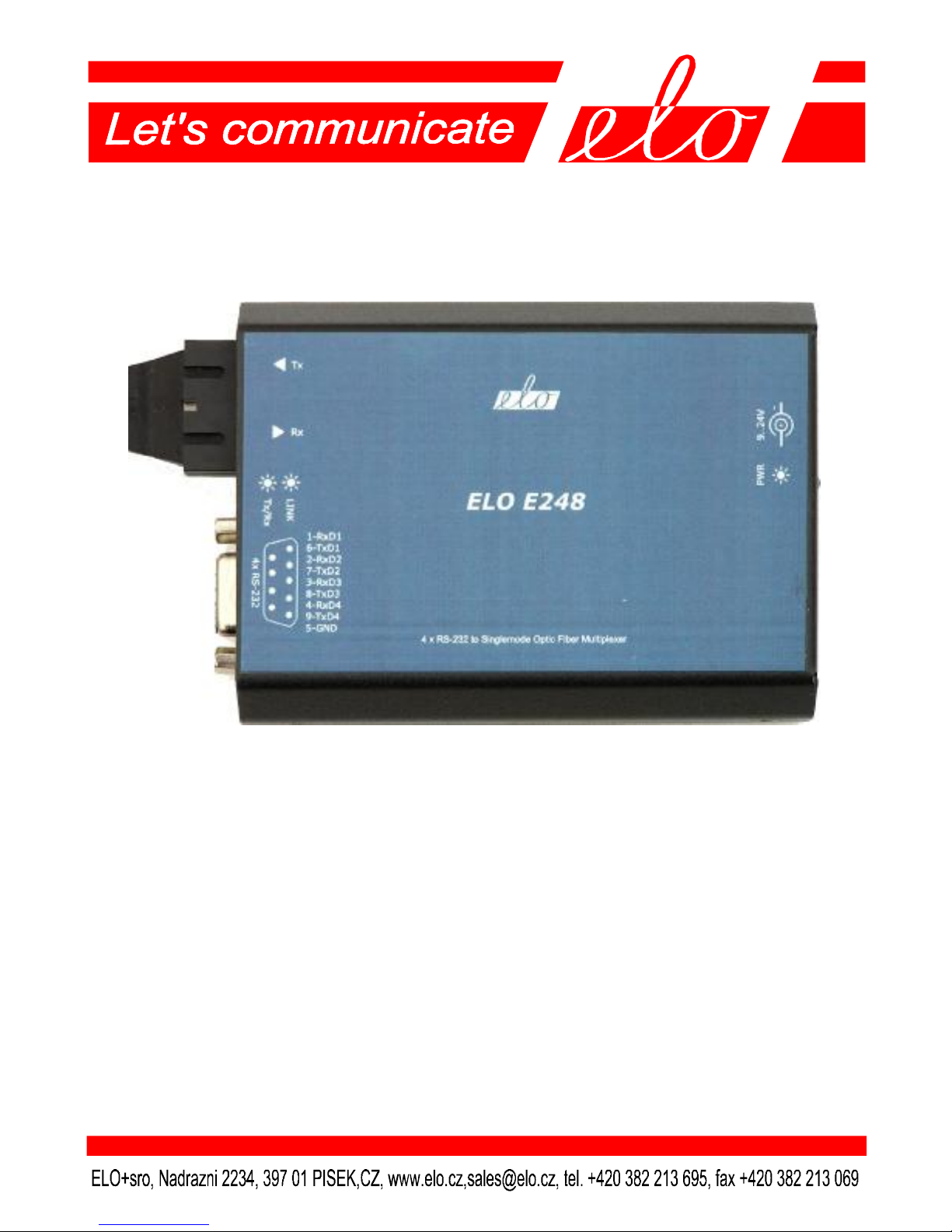
ELO E246, ELO E247,
ELO E248, ELO E249,
ELO E24A, ELO E24B
Operation manual
Page 2

ELOE246,7,8,9,A,BZKE001
2
1.0 Introduction...........................................................................3
1.1 Use of the multiplexer............................................................3
2.0 Operation principles...............................................................3
3.0 Installation.............................................................................3
3.1 Metallic interfaces connection...............................................3
3.2 RS232 interface......................................................................4
3.3 RS422 interface......................................................................5
3.4 Two multiplexers interconnection..........................................5
3.5 Power Connection..................................................................6
4.0 Specification..........................................................................6
4.1 Parameters.............................................................................6
4.2 Dimensions and weight..........................................................6
4.3 Other......................................................................................6
5.0 Testing...................................................................................6
6.0 Troubleshooting.....................................................................7
7.0 Ordering information............................................................7
7.1 Related products.....................................................................7
Page 3

ELOE246,7,8,9,A,BZKE001
3
1.0 Introduction
Fiber Optic (SINGLE MODE and/or MULTI MODE) has been used for signal
transmission in automation for communication more and more often.
The main advantage of Fiber Optic is its immunity to electromagnetic
interference, slight radiation and high transmission capacity
1.1 Use of the multiplexer
Using a pair of multiplexers several absolutely independent transmission channels
over one optic line can be estabilished. The individual channels can be used that
way:
- several independent simultaneous applications (according to the number of
channels),
- simultaneous data transfer over one channel and control, status or clock signals
over the rest of channels.
Multiplexer can work without any setting.
2.0 Operation principles
Multiplexer asociates following serial channels to one pair of fibers:
Interface / model E246 E247 E248 E249 E24A E24B
Number of RS232 4 4 4 -- -- - Number of RS422 -- -- -- 2 2 2
The data rate in one channel is absolutely independent on other channels and the
data rate can be any range from zero to maximum 230 000 kbps.
Multiplexer is independent on communication protocol.
3.0 Installation
There are three different problems of installation to discuss: RS232 or RS422 link
connection, optic fiber link connection, respectively two multiplexers
interconnecting and power supply connection.
3.1 Metallic interfaces connection
All interfaces except optic fiber and supply input are taken out to DB9 female
connector. The connector description is in tables shown in following chapters.
The interfaces concentrated to one connector can be distributed to separate
connectors by ELO E24E and ELO E24F cables.
Page 4

ELOE246,7,8,9,A,BZKE001
4
3.2 RS232 interface
There are three different ways how to use the multiplexer ELO E246, E247 or
E248 with RS232 interfaces:
1 - Four independent duplex channels with RS232 interface. Firs with signals
TxD1 and RxD1 (contacts 6,1), second with signals TxD2, RxD2 (contacts 7,2),
third TxD3, RxD3 (contacts 8,3) and fourth TxD4 and RxD4 (contacts 9,4).
Contact 5 - GND is common for all channels. When the cable ELO E24E is used
each channel has its own standard connector DB9F with the signals RxD (contact
2), TxD (contact 3) and GND (contact 5).
2 - One duplex line, transmitting data (TxD and RxD) through the channel e.g.
(No.1) and accompaniing control and status signals, RTS, CTS, DTR, DSR and
DCD through the rest of channels.
3 – Two duplex lines, each uses one channel for data and second one for control
and status signal - handshake (e.g. RTS-CTS, or DTR-DSR).
The data rate is allowed in range from 0 to 230 000 bps.
The cable between end device and multiplexer must not exceed 15 m.
contact signal meaning direction
1 RxD1 received data of the 1st RS232 from the multiplexer
2 RxD2 received data of the 2nd RS232 from the multiplexer
3 RxD3 received data of the 3rd RS232 from the multiplexer
4 RxD4 received data of the 4th RS232 from the multiplexer
5 GND common signal ground
6 TxD1 transm. data of the 1st RS232 into the multiplexer
7 TxD2 transm. data of the 2nd RS232 into the multiplexer
8 TxD3 transm. data of the 3rd RS232 into the multiplexer
9 TxD4 transm. data of the 4th RS232 into the multiplexer
Page 5

ELOE246,7,8,9,A,BZKE001
5
3.3 RS422 interface
RS422 is destined for two point connection. The signal is symmetric, differential.
Each signal is distributed over its twisted pair. The wires are marked for instance
Rx1+ and Rx1-. In idle state (which is according to stop bit in assynchronneus
mode) the potential of Rx1+ is higher than the potential of Rx1-. The connector is
described in following table:
To improve the transfer over the RS422 line the terminating resistors 100 -120 Ω
can be connected between the corresponding pair of wires. The installation of
terminators is very easy by the switching on the
switches on the back side of multiplexer.
The maximum cable length between end device
and multiplexer must not exceed 1200 m.
Multiplexer can work without any setting – the
data rate can be any in the range from 0 to
230 000 bps. The transfer does not depend on
other channels and on the communication
protocol.
3.4 Two multiplexers interconnection
The optic cable is connected through the SC connector (models E247, E249,
E24A, E24B), or ST one (models E246, 249). The remote multiplexer’s
transmitter must be connected to local receiver and remote receiver must be
connected to local transmitter (the fibers are crossing). The correctly connected
multiplexers are indicated by LINK indicator.
contact signal meaning direction
1 Rx1+ received data of the 1st RS422 from the multiplexer
2 Rx2+ received data of the 2nd RS422 from the multiplexer
3 Tx1+ transm. data of the 1st RS422 into the multiplexer
4 Tx2+ transm. data of the 2nd RS422 into the multiplexer
5 GND ground
6 Rx1- received data of the 1st RS422 from the multiplexer
7 Rx2- received data of the 2nd RS422 from the multiplexer
8 Tx1- transm. data of the 1st RS422 into the multiplexer
9 Tx2- transm. data of the 2nd RS422 into the multiplexer
SW terminated line
1 On= Rx1
2 On=Rx2
3 On=Tx1
4 On=Tx2
5-8
not used
Page 6

ELOE246,7,8,9,A,BZKE001
6
3.5 Power Connection
The external power supply must have from 9V to 24V DC. It can be connected
through the DC connector on the back side of the multiplexer. The correct
function is signalized by PWR indicator. The power take off depends on the
voltage rating of the used supply. If the voltage is 12V it doesn’t exceed 400 mA,
if 24V 150 mA.
4.0 Specification
4.1 Parameters
Transferred interfaces E246, E247, E248 4 x RS232 (V.24),
Transferred interfaces E249, E24A, E24B 2 x RS422 (V.11),
Interfaces connector DB9 female,
Transfer mode duplex
Optic connector E246, E249 ST
E247, E248, E24A, E24B SC
Optic cable E246, E247, E249, E24A two multimode fibers 50 / 125 µm
or 62.5 / 125 µm
Optic cable E248, E24B two single mode fibers 9 / 125 µm
Maximum data rate RS232 230 000 bps,
Maximum data rate RS422 230 000 bps,
Minimum Maximum data rate 0 bps,
Supplying external DC 9-24V/400-150 mA
4.2 Dimensions and weight
Length x width x height 120x80x25 mm
Weight 160 g
4.3 Other
Storage temperature - 10 o to +55 o C
Working temperature + 0o to +50o C
Humidity 0 – 85% ((non-condensing)
5.0 Testing
In case of proper installation of power supply the PWR diode is alight. The correct
optic link installation is indicated by LINK. The Tx/RxD indicator must blink
during transmission.
Page 7

ELOE246,7,8,9,A,BZKE001
7
6.0 Troubleshooting
Symptom Action
Multiplexer does not Check the LINK – it is shining when
work after installation the optic cables are connected properly.
Check the power supply (PWR).
Check the interfaces’ connection.
Check the correct directions of transmition.
Connection in normal Check the power supply.
operation quit working Check if the cables are OK.
Turn off and on the power supply and detect
if multiplexer will start again.
7.0 Ordering information
The ordering codes are:
ELO E246 MUX 4xRS232 / ST multimode,
ELO E247 MUX 4xRS232 / SC multimode,
ELO E248 MUX 4xRS232 / SC single mode,
ELO E249 MUX 2xRS422 / ST multimode,
ELO E24A MUX 2xRS422 / SC multimode,
ELO E24B MUX 2xRS422 / SC single mode.
7.1 Related products
ELO E0Q6 Power supply 12V / 500 mA
ELO E24E cable 4 x RS232,
ELO E24F cable 2x RS422.
Page 8

ELOE246,7,8,9,A,BZKE001
8
 Loading...