

Page 1
RS-422 / Multimode Fiber Optic Converter
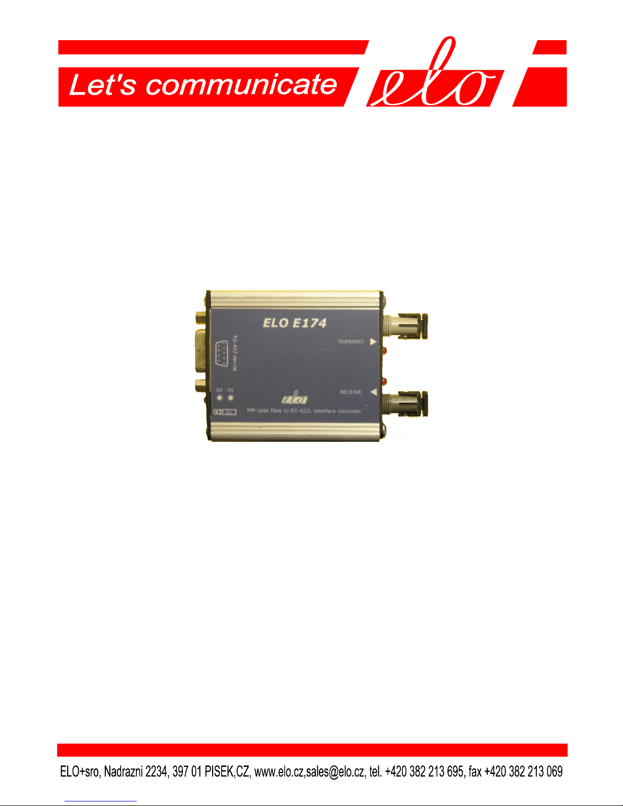
ELO E174
Operation manual
Page 2

ELOE174ZKE002
2
1.0 Introduction ............................................................................. 3
1.1 Use of the converter ................................................................. 3
2.0 Operation principles ................................................................ 3
3.0 Installation ............................................................................... 3
3.1 Optic link connection ............................................................... 3
3.2 RS-422 interface connection ................................................... 3
3.3 Power supply connection ......................................................... 4
4.0 Specification ............................................................................. 5
4.1 Parameters ............................................................................... 5
4.2 Optical parameters ................................................................... 5
4.3 Other ......................................................................................... 5
5.0 Testing ...................................................................................... 5
6.0 Troubleshooting ....................................................................... 6
7.0 Ordering Information .............................................................. 6
Page 3

ELOE174ZKE002
3
1.0 Introduction
RS-422 (V.11) is a duplex interface for two devices´ communication. The
symmetric signals are transmitted via the twisted pair and they are immune to the
interference. Maximum range is 1200m which can be increased using repeaters.
1.1 Use of the converter
The fibre optic cable is immune to electromagnetic interference and atmospheric
electricity influences, it provides maximum DTE protection and high
communication reliability. The distance between devices is not more than 2km so
using multimode fibres is economically convenient in automation.
2.0 Operation principles
The converter transfers Tx signal of the RS-422 interface to the transmitting optic
fiber and copies it from the receiving optic fiber to Rx of the RS-422 interface.
Maximum data rate limit is 115.2 kbps. LED diodes indicate the transmitted and
received signal.
3.0 Installation
This part describes the ELO E174 converter installation principles.
3.1 Optic link connection
ST 400 connectors are used to connect the fiber optic cable. To connect two
converters, the TRANSMIT connector of the local converter has to be connected to
the RECEIVE connector of the remote converter and the RECEIVE of the local
converter has to be connected to the TRANSMIT connector of the remote one. The
cable has to be multimode 50/125 or 62.5/125μm and it should not be longer than
2 km are recommended.
3.2 RS-422 interface connection
RS-422 interface connector is DB9F (female), signals assignment to the contacts
(see the Fig.). If the OUT +5V and IN +8V signals are not used the DTE can be
connected to the converter via the cable up to 1200m long or the tolerable supply
voltage decrease limits the cable length.
Page 4

ELOE174ZKE002
4
DTE CABLE CONVERTER
3.3 Power supply connection
To supply the converter, the external power supply of 6V via SCJ 2.5mm connector
(yellow LED labelled 6V indicates it) or via 9 contact (IN+8V) is used, e.g. from
the DTE. The green LED labelled 8V indicates this supply. The DTE receives the
external supply information via OUT+5V signal. This arrangement enables to back
up the converter supply. The external supply 6V is isolated from the RS-422 link.
Maximum take off is 170mA.
Caution!
Do not connect the DC connector if the supply is on.
Rx+
Rx Tx+
Tx-
GND
Ready
Vcc out
stínění
DB9 Signál
female RS-422
1 RxA
2 RxB
3 TxA
4 TxB
5 NC
6 NC
7 GND signal
8 OUT +5V
9 IN +8V
kryt
stínění
Page 5

ELOE174ZKE002
5
4.0 Specification
4.1 Parameters
Interface RS-422
RS-422 connector DB9F
Transmission mode full duplex
4.2 Optical parameters
Wavelength 820mm, multimode fibre
Optic fibre 2x 50/125 or 62.5/125
Connectors ST
Fibre optic cable two single mode fibres 9/125 µm
Maximum data rate 115 200 bps
4.3 Other
Supply ext. DC supply of 6V/200mA galv. isolation
DC supply of 8V/170 mA (from DTE)
Dimension: Length 80mm
Width 55mm
Height 20mm
Weight 80g
Stocking temperature -10° to +55°C
Working temperature +0° to +50°C
Humidity 0 – 85% (non-condensing)
5.0 Testing
When the power supply is connected the
appropriate LED has to be alight. To work
properly at least one of 8V or 6V LED must be
alight.
The LED diodes respective to the optic
transmitter/receiver (TRANSMIT/RECEIVE)
must blink during transmission.
Page 6

ELOE174ZKE002
6
6.0 Troubleshooting
Symptom Action
The modem does not work Check if the optic cables and the RS-422 cable
after installation. are connected properly.
Check the power supply.
Connection in normal Check the power supply.
operation quit working Check if the cables are connected properly.
Check if the power supply is on.
Check if the DTE works properly.
7.0 Ordering Information
Supply code is ELO E174.
Option:
Supply code for power supply 6V/200mA is ELO E0Q0.
Page 7

ELOE174ZKE002
7
Note
Page 8

ELOE174ZKE002
8
 Loading...