

Page 1
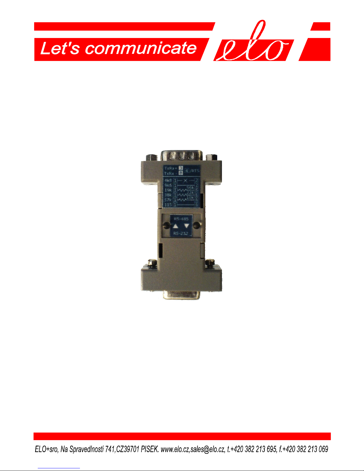
RS-232/RS-485 Converter with HW and Automatic
Control without Galvanic Isolation of the Interface
ELO E06G
Operation manual
Page 2

ELOE06GZKE001
2
1.0 Introduction...........................................................................2
1.1 Use of the converter...............................................................2
2.0 Operation principles...............................................................3
3.0 Installation.............................................................................3
3.1 Converter connection to RS-232 Interface.............................3
3.2 RS-485 link connection..........................................................4
3.3 Converter setting....................................................................5
3.4 Power Supply Connection......................................................5
4.0 Specifications.........................................................................6
4.1 Electrical parameters.............................................................6
4.2 Other......................................................................................6
5.0 Testing...................................................................................7
6.0 Troubleshooting.....................................................................7
7.0 Ordering information............................................................7
1.0 Introduction
RS-232 interface is designed for two terminal equipments connection (DTE).
RS-232 interface range is limited to 15m distance. RS-485 interface signals
transmission enables to increase communication range, transmission interference
immunity and communication partners´ number.
1.1 Use of the converter
The converter increases transmission immunity against electrical disturbance but
not against atmospheric electricity influences! To lead the cable outside
buildings, it is necessary to provide additional over-voltage protection on the input
points. The converter allows transmission rate up to 115200 bps. This maximum
attainable rate decreases due to the line length and/or its impedance growth.
Recommended maximum line length is 1200 m at the rate of 9600 bps.
Page 3
ELOE06GZKE001
3
2.0 Operation principles
RS-485 interface is used to two-way simultaneous communication in one pair of
conductors. For this reason, the transmission has to be half-duplex that means
switching off RS-485 transmitter when receiving to allow transmitting to other
communication partners and switching on during its own transmitting only. There
are two methods how to operate the transmitter:
1) The transmitter is controlled from DTE by signal RTS or its invert polarity.
2) DTE does not use RTS (this interface does not dispose this signal or SW does
not use it) and the converter has to interpret its signal TxD automatically. At
the TxD changing moment from idle state (from the negative to positive
polarity), the converter activates the link transmitter automatically. The
transmitter is switched off after the certain time τ of RTS switching off or
TxD return to the neutral polarity. Time interval length τ has to be dependent
on applied transmission rate because in the automatic mode there it is
necessary to keep the transmitter active for the period equal to one byte
transmission time.
In the automatic mode, every device that is to transmit has to wait at least for the
time τ from the last byte recorded on RS-485 bus. If it is to the contrary the first
transmitted byte would be damaged.
3.0 Installation
E06G has to be installed with the respect for specifications of both interfaces.
3.1 Converter connection to RS-232 Interface
Signals assignment to the contacts and DTE-DCE connection is in the table:
abbrev DTE E06G transmit direction
connector connector
SIGNAL (DB9M) (DB9F) DTE E06G
Signal Ground SG 5 5 <> <>
Transmitted Data TxD 3 3 output input
Received Data RxD 2 2 input output
Request to Send RTS 7 7 output input
Clear to Send CTS 8 8 input output
Data Set Ready DSR 6 6 input - Data Terminal Ready DTR 4 4 output - Data Carrier Detect DCD 1 1 input --
Page 4

ELOE06GZKE001
4
!!! Be careful of a frequent mistake !!!
The DTE – DCE cable has to be connected 1:1.
ELO E06G transmits RxD and TxD signals. Control signals are not transmitted.
The converter contains local jumpers RTS-CTS and DTR-DST-DCD. Maximum
data rate is 115 200 bps.
3.2 RS-485 link connection
The DB9M connector is
used to the link connection
Single DTE can be
connected via bus
(see fig.) with up to 32
partners.
The RS-485 connector description and the internal passive terminator:
Contact 1 2 3 4 5 6 7 8 9
Signal TAU1 TAU2 TxRx+ RTSpol GND TAU3 T TxRx- +Supp
Internal terminator 1k5
Totally correct RS-485
bus handling is shown
in the picture. RS-485
link must be terminated at both ends. The
resistors (called passive terminators) must
be connected between
A and B wires and
their value must be
100-120 Ω. These ter-
minators are used for
the converter
impedan-ce matching,
they suppress the
undesi-rable echo and
Page 5

ELOE06GZKE001
5
they influence the transfer immunity against interference.
The third wire is the other important component of bus. The wire interconnects
the users signal grounds thereby eliminate the zero potentials differences. This
wire has to be connected to DTEs shields.
There are also the active terminators beside the passive ones. Only one active
terminator can be installed to one metallic section of the link and its role is
important at the moments when no one user is transmitting and all of them are in
high impedance state (so-called the third state of the bus). Active terminator is an
resistor divider which makes voltage higher or equal than 200 mV between A and
B wires. Some types of RS-485 receivers don’t guarantee a correct interpretation
of the third state – it must be transferred as IDLE. The active terminator can solve
this problem. It can be realized with one internal resistor 680 Ω (jumper 7-3) and
one external resistor 680 Ω between 5 and 8 contacts.
3.3 Converter setting
To work properly, the converter needs time out setting τ. For this case there are
contacts TAU1, TAU2 and TAU3 (numbers 1, 2 and 6) on the RS-485 connector.
How to use them is shown at the table below:
Data rate 2 1 6
4800 not used not used not used
9600 not used
19200 not used 56k
38400 not used 22k
57600 not used 10k
115200 not used
When the RTS control mode is set it is suitable to minimize the τ influence setting
the smallest τ (connection 1-6 for the maximum data rate).
If DTE sets RTS to „ON“ polarity permanently, the converter would have his
transmitter switched on all the time and the RS-485 line couldn’t be shared. In
this case the RTS influence can be switched off by the connection between
RTSpol and GND (contacts 4-5). This way a RTS polarity has been changed and
RTS can be active in the state „OFF“.
3.4 Power Supply Connection
The converter can be supplied ether through the DC connector 2.35mm, or
through the contacts 9-5 of the RS-485 connector (DB9M). The power take-off
Page 6

ELOE06GZKE001
6
from the DC supply 6 to 24 V mustn’t exceed 100 mA. The converter is protected
against the reversing of polarity.
4.0 Specifications
4.1 Electrical parameters
Interface RS-232 / RS-485
Transmitted signals TxD and RxD
Control RS-232 signals local jumpers RTS-CTS
DTR- DSR-DCD
RS-232 connector DB9F, DCE
RS-485 connector DB9M
Transmission mode half-duplex, RTS or /RTS controlled, or
automatically by time constant 0.1 to 2.5 ms
Power supply external DC supply 6-24V / 100mA
Minimum/max supply voltage 6 / 24 V
Connector EIAJ 2.35mm and RS-485 connector
Isolation between interfaces without galvanic isolation
Permissible over-voltage on the the line must not be exposed to the
line under ČSN 33 0420: atmospheric discharge influences
Required link impedance 100Ω
4.2 Other
Range 1200m, double-wire link
Maximum transmission rate 115 200 bps
Minimum data rate AUT/ RTS 4 800 / 50 bps
Dim.: width x length x height 34 x 63 x 19 mm
Weight 25 g
Stocking temperature - 10 o to +55 o C
Working temperature + 0o to +50o C
Humidity 0 – 85% (non-condensing)
Page 7

ELOE06GZKE001
7
!!!CAUTION!!!
Unless otherwise specified on the product, as for permissible over-voltage, the
converter can be used in the environments where lightning over-voltage is not
necessary to be considered. Converters connection to the lines exposed to the
atmospheric electricity influences is prohibited unless separate line protection is
carried out e.g. via very fast lightning arrestor.
5.0 Testing
When the supply is switched on, connect positive terminal to the 3 contact and the
negative terminal to the 5 contact of the DC power supply of 5 to 9 V on the RS232 connector. The voltage of c. 2 - 3V has to be on the 3-8 contacts of the RS485 connector.
6.0 Troubleshooting
Symptom Action
Converter does not work Check if the link is connected properly
after installation Check if 3-8 contacts are not changed
Check the power supply.
Check RS-232 connection and RTS polarity.
Check if the time constant selection is right.
Connection in normal Check the power supply
operation quit working Check the cable connection
Use the test as with 5.0
7.0 Ordering information
Supply code is ELO E06G.
Ordering code for power supply is ELO E0Q4. Supply connector (for cable) can
be supplied separately.
Page 8

ELOE06GZKE001
8
 Loading...