

Page 1

AMM170TK2/AMM17TK2/AMM18TK2/AMM19TK2/AMM19TK2(HB) 1
back of the monitor
GNINRAW
fosresuehtmrofniotdesusi"GNINRAW"eltitehT
ro,htaed,yrujniehttcilfnidluoctahtsesuacelbissop
.stne
itapehtotegamadytreporp
NOITUAC
fosresuehtmrofniotdesusi"NOITUAC"eltitehT
hguohtlastneitapehttcilfnidluoctahtsesuacelbissop
.sht
aedesuacothguoneerevestonthgimti
ETON
smetifosresuehtmrofniotdesusi"ETON"eltitehT
,noitallatsnifosmretniecnatropmifoerataht
iuqEehtfoecnanetniamro,noitarepo
hguohtlatnemp
ehtotmrahylidobehttcilfnitonseoderuliafeht
.stneitap
ADA VN INT’L CORP .2005
“ELO” is a Registered trademark of Elo T ouchSystems, Inc.,
All other trademarks are the property of their reference owners.
This document is subject to change without notice.
Advan provides this information as reference only. Reference to other vendor’s products
does not imply any recommendation or endorsement.
Revision Control
etaDnoitpircseD
Rev. A 071505
rebmuntnemucoD
Page 2

2 User’s Guide
TABLE OF CONTENTS
Quick Setup...............................................................................................3~5
Product Features...........................................................................................6
Warnings and Cautions.................................................................................8
Symbol Explanations...................................................................................1 1
EU Declaration of Conformity for Medical Applications..........................12
Prepare for Unpack.....................................................................................12
Screen Position Adjustment.......................................................................13
Safety Precaution........................................................................................14
Cleaning Y our Monitor.................................................................................14
Preset Modes..............................................................................................15
Power Management Function....................................................................16
DDC..............................................................................................................17
Installation.....................................................................................................17
Display for Video and Image Back............................................................18
Connecting with Video Equipment............................................................18
User Controls...............................................................................................19
OSD Screen Basic Section (VGA)...........................................................20
OSD Screen Basic Section (DVI).............................................................22
OSD Screen Basic Section (C-Video or S-Video).................................24
OSD Function Description (Under Analog Display)................................26
OSD Function Description (Under Digital Display).................................27
OSD Function Description (Under C-Video or S-Video Display)..........28
Troubleshooting...........................................................................................29
Specification of (AMM19TK2)....................................................................30
Specification of (AMM19TK2/HB).............................................................31
Classification...............................................................................................35
Electromagnetic Compatibility............................................................36~39
Description of Warranty........................................................................41~42
T ounchscreen User’s Manual..............................................................43~44
Page 3
AMM170TK2/AMM17TK2/AMM18TK2/AMM19TK2/AMM19TK2(HB) 3
Quick Setup (IBM/IBM Compatible under Windows 95/98/ME/2000)
Please Read Carefully When Setting Up Your New Monitor
Monitor Screen Adjustment and Resolution Setting Procedure for IBM/IBM Compatible
Computers with Windows based OS system.
Before adjusting the monitor, all the necessary drivers should be installed to your System
and resolution has to be set to manufacturer’s recommended preset of 1280 x 1024 @ 60Hz,
70Hz, 72Hz or 75 Hz.
To check the resolution, press the “UP” button on the monitor and the “Information” will
display under the OSD. Information will have Resolution, Horizontal and V ertical (Refresh rate)
frequency information.
To change the resolution to its factory recommended preset.
1. On a Windows 95, 98, ME or 2000, press right button on a Mouse to execute the Pop-up
menu.
2. Press “Properties” to execute the “Display Properties”
3. Press “Setting” and change the resolution to 1280 x 1024.
4. Press “Apply or OK” to select and press “OK” to keep the selected resolution.
5. Go back to “Display Properties” - “Setting” - “Advanced properties” - “Adapter”
6. On Adapter property, change the refresh rate to 60Hz, 70Hz, 72Hz or 75Hz. If you don’t
have these options, choose “Adapter Default”. (60Hz recommended)
Screen Adjustment Procedure
1. Press the “AUTO” button.
2. If you still don’t have a clear display monitor, please refer to step 3.
3. Start “Shut Down” in Windows 95/98/ME/2000 - It will display moire on screen
4. Press “Up” button then the OSD menu will pop-up.
5. Adjust the “Frequency” under the OSD to reduce or get rid of the vertical display noise
(Jail bars).
6. Once the vertical display noise disappears, press adjust the “Phase” to reduce or get rid of
the horizontal display noise (Snowy effect).
Page 4
4 User’s Guide
Quick Setup (IBM/IBM Compatible under Windows NT 4.0)
Please Read Carefully When Setting Up Your New Monitor
Monitor Screen Adjustment and Resolution Setting Procedure for IBM/IBM Compatible
Computers with W indows based OS system.
Before adjusting the monitor, all the necessary drivers should be installed to your System
and resolution has to be set to manufacture’s recommended preset of 1280 x 1024 @ 60Hz,
70Hz, 72Hz or 75Hz.
To check the resolution, press the “UP” button on the monitor and the “Information” will
display under the OSD. Information will have Resolution, Horizontal and V ertical (Refresh rate)
frequency information.
To change the resolution to its factory recommended preset.
1. On a Windows NT 4.0, press right button on a Mouse to execute the Pop-up menu.
2. Press “Properties” to execute the “Display Properties”
3. Press “Setting” and change the resolution to 1280 x 1024.
4. Change “Refresh Frequency” to 60Hz, 70Hz, 72Hz or 75Hz. (60Hz recommended)
Screen Adjustment Procedure
1. Press the “AUTO” button.
2. If you still don’t have a clear display monitor, please refer to step 3.
3. Start “Shut Down” in Windows 95/98/ME/2000 - It will display moire on screen
4. Press “Up” button then the OSD menu will pop-up.
5. Adjust the “Frequency” under the OSD to reduce or get rid of the vertical display noise
(Jail bars).
6. Once the vertical display noise disappears, press adjust the “Phase” to reduce or get rid of
the horizontal display noise (Snowy effect).
Page 5
AMM170TK2/AMM17TK2/AMM18TK2/AMM19TK2/AMM19TK2(HB) 5
Quick Setup (Macintosh)
Please Read Carefully When Setting Up Your New Monitor
1. Set your Macintosh Adapter on pages 23 and 24.
2. Push the “APPLE” icon on the upper left corn and execute Control Panel->
Monitors&Sound. Select “Thousands” for the Color Depth, Select “1280X1024, 60Hz,
70Hz, 72Hz or 75Hz” for the Resolution. (60Hz recommended)
* On some Apple G3 or newer systems, you may not need to use the Macintosh Adapter.
Screen Adjustment Procedure
1. Press the “AUTO” button on the monitor.
Page 6

6 User’s Guide
INTRODUCTION
Congratulations on your purchasing of the AMM170TK2/AMM17TK2/AMM18TK2/
AMM19TK2/AMM19TK2(HB) high performance TFT LCD monitor .
Product Description and Intended Use
The AMM170TK2/AMM17TK2/AMM18TK2/AMM19TK2/AMM19TK2(HB) Monitor is an
intelligent, microprocessor-based TFT -LCD monitor intended for use in medical applications. It has an ergonomically designed display and is compatible with most analog RGB
(Red, Green, Blue) display standards.
The AMM170TK2/AMM17TK2/AMM18TK2/AMM19TK2/AMM19TK2(HB) Monitor has the
following features:
• Advanced Viewing Solution (AVS): Our sophisticated filter extends the viewing angle of
the screen image, without sacrificing contrast ratio and brightness.
• Advanced Timing Setup (A TS): A unique technology from the One T ouch Auto Adjustment.
Pressing the Auto Adjust button on the front panel, automatically optimizes position,
phase, clock, contrast and color balance. This allows the user to maximize the perfect
screen setting in the shortest amount of time.
• Advanced Mounting Solution (AMS): Improve flat panel environment, utilizing numerous
ergonomic mounting solutions to allow creative use in conjunction to product application.
• The monitor is able to properly function even in case of upgrade video cards or software
because of the wide auto-scanning compatibility range without requiring to buy a new
monitor.
• The internal microprocessor digitally controls auto-scanning. For horizontal scan
frequencies between 24.8 KHz and 60.2 KHz, and vertical scan frequencies between 50.0 Hz
and 85.1 Hz. In each frequency mode, the microprocessor-based circuitry allows the monitor
to function at the precision-of a fixed frequency.
• The resident memory allows for storing factory default settings and also additional user
adjustment parameters.
• The maximum resolution achievable is SXGA (1280 x 1024)
• The compact and sleek cabinet design saves lot of your desk space and makes your desk
look neat and tidy.
• The monitor is compliant with VESA-DPMS power management standard. In order to
save energy, the monitor must be connected to a system compliant with the standard.
The monitor is certified by UL International to medical standard UL60601-1, EN60601-1 and
EN60601-1-2. It is also CE marked for sale into the European Community for integration or
use with medical products.
Page 7
AMM170TK2/AMM17TK2/AMM18TK2/AMM19TK2/AMM19TK2(HB) 7
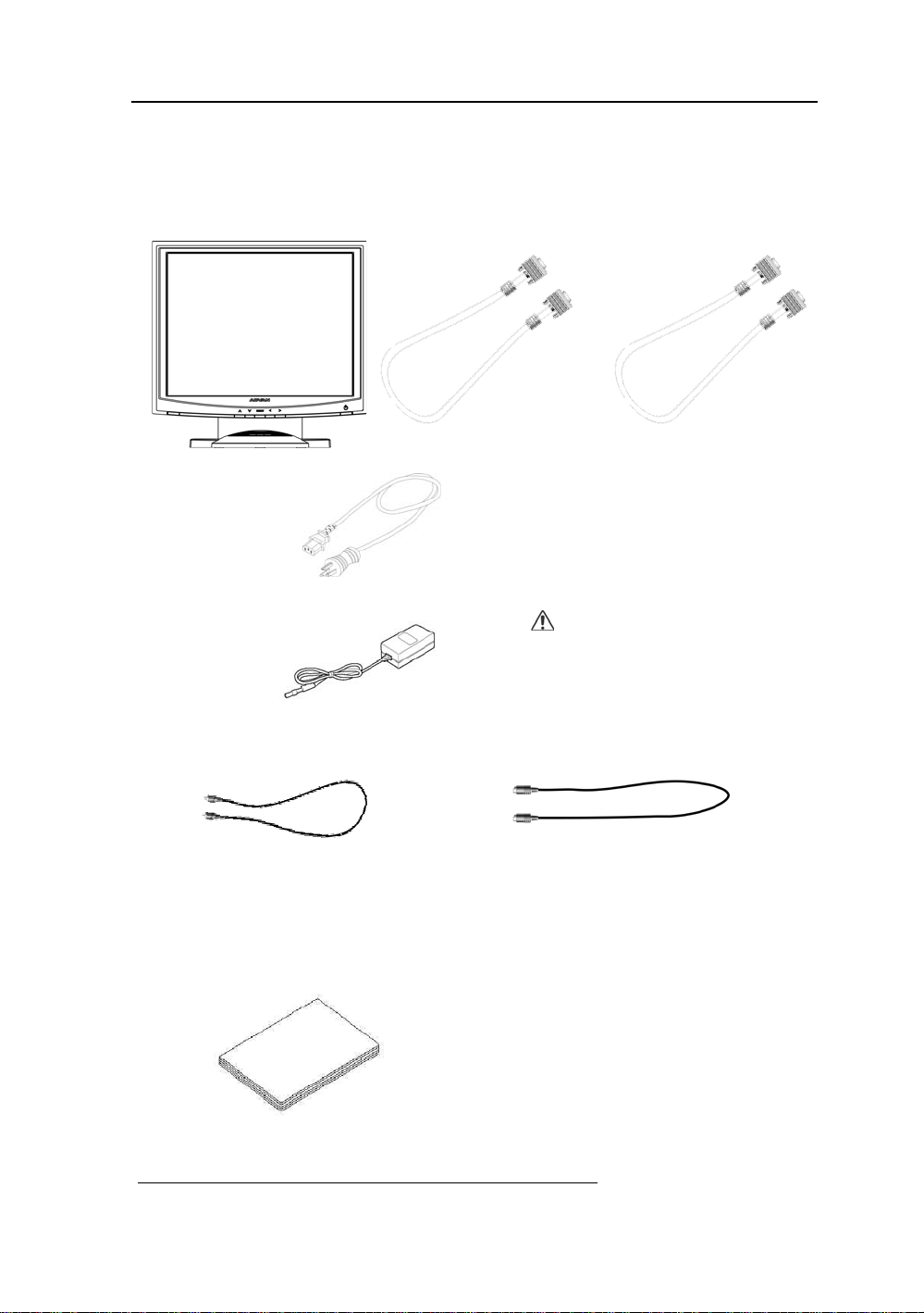
Product Description
Please check the following items are present when you unpack the box, and save the packing
materials in case you will need to ship or transport the monitor in future.
• AMM170TK2, AMM17TK2, AMM18TK2, AMM19TK2 or AMM19TK2/HB LCD
Monitor and two video cable (1) VGA HDDB15 cable (1) DVI-D cable
• AC Power cord
• AC-Adapter
• Composite V ideo BNC Jack Cable and Super V ideo Cable
• User Manual
CAUTION
Manufacturer : Ault Korea
Model No : MW116
*Touchscreen Data Cable and Floppy Disk (Touchscreen driver) optional
Page 8
8 User’s Guide
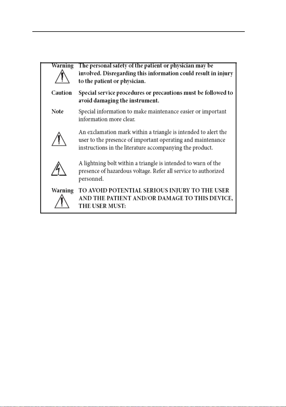
W arnings and Cautions
Please read this manual and follow its instructions carefully. The words warning, caution,
and note carry special meanings and should be carefully reviewed:
Warranty is void if any of these warnings ar e disregarded.
ADVAN Int’l Corp accepts full responsibility for the effects on safety, reliability, and
performance of the equipment only if:
• Re-adjustments, modifications, and/or repairs are carried out exclusively by
ADV AN Int’l Corp.
• The electrical installation of the relevant operating room complies with the
applicable IEC and CE requirements.
Warning Federal law (United S tates of America) restricts this device to use by ,
or on order of a physician.
The ADVAN Int’l Corp AMM170TK2/AMM17TK2/AMM18TK2/AMM19TK2/
AMM19TK2(HB) monitor has been tested under UL 60601-1 standard and UL listed for
Medical application.
ADVAN Int’l Corp reserves the right to make improvements in the product(s) described
herein. Product(s), therefore, may not agree in detail to the published design or
specifications. All specifications are subject to change without notice. Please contact
ADVAN Int’l Corp directly or phone your local ADVAN Int’l Corp sales representative or
agent for information on changes and new products.
Page 9

AMM170TK2/AMM17TK2/AMM18TK2/AMM19TK2/AMM19TK2(HB) 9
Warnings
1. Read the operating manual thoroughly and be familiar with its contents prior to using
this equipment.
2. Carefully unpack the unit and check if any damage occurred during shipment.
3. Should any solid object or liquid fall into the panel, unplug the unit and have it checked
by qualified personnel before operating it any further.
4. Uplug the unit if it is not to be used for an extended period of time. To disconnect the
cord, pull it out by the plug. Never pull the cord itself.
5. Be a qualified physician, having complete knowledge of the use of this equipment.
6. Test this equipment prior to a surgical procedure. This monitor was fully tested at the
factory before shipment.
7. Avoid removing covers on control unit to avoid electric shock.
8. Attempt no internal repairs or adjustments not specifically detailed in this operating
manual.
9. Pay close attention to the care, cleaning instructions in this manual. A deviation may
cause damage (refer to the Cleaning section on page 14).
10. DO NOT STERILIZE MONITOR.
11. Read the entire instruction manual before assembling or connecting the camera.
12. Do not place the monitor or any other heavy object on the power cord. Damage to the
cable can cause fire or electirc shock.
13. Monitor with power supply is suitable for use in patient environment.
14. DO NOT stack more than 8 boxes high
This equipment has been tested and found to comply with the limits for medical devices in
IEC 601-1-2:2003. These limits are designed to provide reasonable protection against
harmful interference in a typical medical installation.
This equipment generates, uses and can radiate radio frequency energy and, if not installed
and used in accordance with the instructions, may cause harmful interference to other
devices in the vicinity. However, there is no guarantee that interference will not occur in a
particular installation. If this equipment does cause harmful interference to other devices,
which can be determined by turning the equipment off and on, the user is encouraged to try
to correct the interference by one or more of the following measures:
- Reorient or relocate the receiving device.
- Increase the separation between the equipment.
- Connect the equipment into an outlet on a circuit different from that to which the other
device(s) are connected.
- Consult the manufacturer or field service technician for help.
Page 10

10 User’s Guide
Cautions
1. The AC Adapter must be plugged into a Grounded power outlet.
2. Use only the proprietary AMM170TK2/AMM17TK2/AMM18TK2/AMM19TK2/
AMM19TK2(HB) power supply for the AMM170TK2/AMM17TK2/AMM18TK2/
AMM19TK2/AMM19TK2(HB) monitor. Make a proper connection by ensuring that the
shrink tubing completely secures the connection between the DC power cord and the
extension cord.
3. Turn power off when unit is not in use.
4. Never operate the unit right after having transported from a cold location directly to a
warm location.
5. Do not expose the monitor to moisture or directly apply liquid cleaners directly to the
screen. Spray the cleaning solution into a soft cloth and clean gently.
6. Handle the monitor with care. Do not strike or scratch the screen.
7. Do not block the monitor cooling vents. The monitor is cooled by natural convection and
has no fan.
8. Do not force the monitor past 28 degrees of vertical when adjusting the screen position.
(For monitors equipped with stands only.)
9. Remove the power module and connection when transporting the unit.
10. Save the original carton and associated packing material. They will be useful should you
have to transport or ship the unit.
11. Allow adequate air circulation to prevent internal heat buildup.
12. Do not place the unit on surfaces (rugs, blankets, etc.) or near materials (curtains,
draperies) that may block the ventilation slots.
13. Do not install the unit near sunlight, excessive dust, mechanical vibration or shock.
14. The unit is designed for operation in a horizontal position. Never operate the unit in a
vertical position.
15. Keep the unit away from equipment with strong magnets (i.e. a large loudspeaker .)
16. Do not expose the monitor to moisture or excessive dust.
17. Equipment with SIP/SOP connectors should either comply with IEC 60601-1 and/or IEC
60601-1-1 harmonized national standard or the combination should be evaluated. Do not
touch the patient with signal input or output connectors.
18. Use only a hospital grade power supply cord.
19. This equipment generates, uses, and can radiate radio frequency energy. If not installed
correctly and or not used in accordance with these instructions, it may cause harmful
interference with other devices. This may be determined by turning the equipment off and
on. The user is encouraged to try to correct the interference through one or more of the
following measures:
• Reorient or relocate the receiving device.
• Increase the separation distance between the equipment.
• Connect the equipment to an outlet on a circuit different from that to which the other
device(s) are connected.
• Consult the manufacturer or field service technican for help.
20. Grounding reliability can only be achieved when the equipment is connected to an
equipment receptacle labeled “Hospital Only” or “Hospital Grade.”
Note To connect to an international power supply, use a an attachment plug appropriate
for the power outlet.
Note Refer to the “Electromagnetic Compatibility” (EMC) section of this manual to
ensure EMC. The AMM170TK2/AMM17TK2/AMM18TK2/AMM19TK2/AMM19TK2(HB)
must be installed and operated according to the EMC information provided in this manual.
Page 11

AMM170TK2/AMM17TK2/AMM18TK2/AMM19TK2/AMM19TK2(HB) 11
Symbol Definitions
IPX1 Degrees of protection against the ingress of water.
Page 12

12 User’s Guide
EU Declaration of Conformity for Medical Applications
A Declaration of Conformity has been filed for this product. A sample of this
document may be found in the addendum which accompanied this manual. For a
copy of the Declaration of Conformity document, please contact ADVAN Int’l
Corp. and request for AMM170TK2, AMM17TK2, AGMM18TK2,
AMM19TK2 and AMM19TK2/HB DOC.
Prepare for Unpack
Before you unpack your monitor, prepare a suitable workspace. Y ou need a stable
and level surface near a grounded wall outlet in an area which is relatively free of
glare from sunlight or other sources of bright light. The monitor is cooled by natural
convection (it has no fan).
For optimum performance, do not block the cooling vents.
While unpacking the monitor, inspect it and other package contents for shipping
damage that could cause a fire or shock hazard. Immediately report any shipping
damage to the carrier or transportation company and contact customer service for
monitor in the future or in case of return.
After you unpack the monitor, make sure the following items are included
• Monitor with 1.5 meter(5ft)monitor-to computer video cable
• AC adapter with cable
CAUTION: AC Adapter must be plugged into Grounded a power outlet)
CAUTION : AC adapter
Manufacturer: Ault korea
Model No: MW116
• Touchscreen cable if monitor has touchscreen option
• This operations manual
Note: Your system provider may offer alternative cords or cables
depending on the installation requirement and local geography issues.
Page 13
AMM170TK2/AMM17TK2/AMM18TK2/AMM19TK2/AMM19TK2(HB) 13
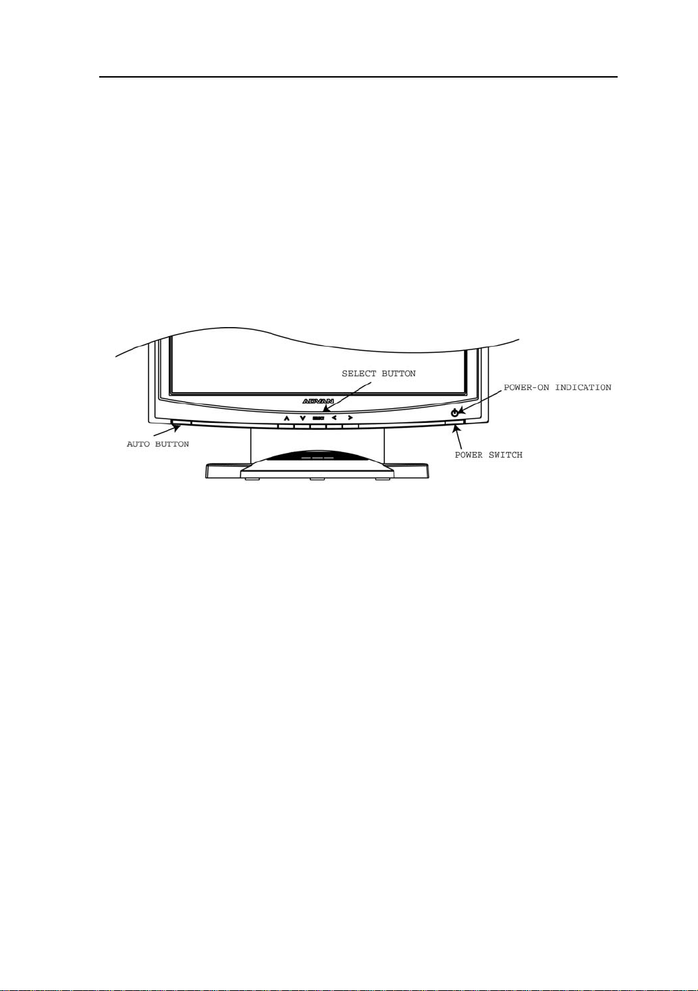
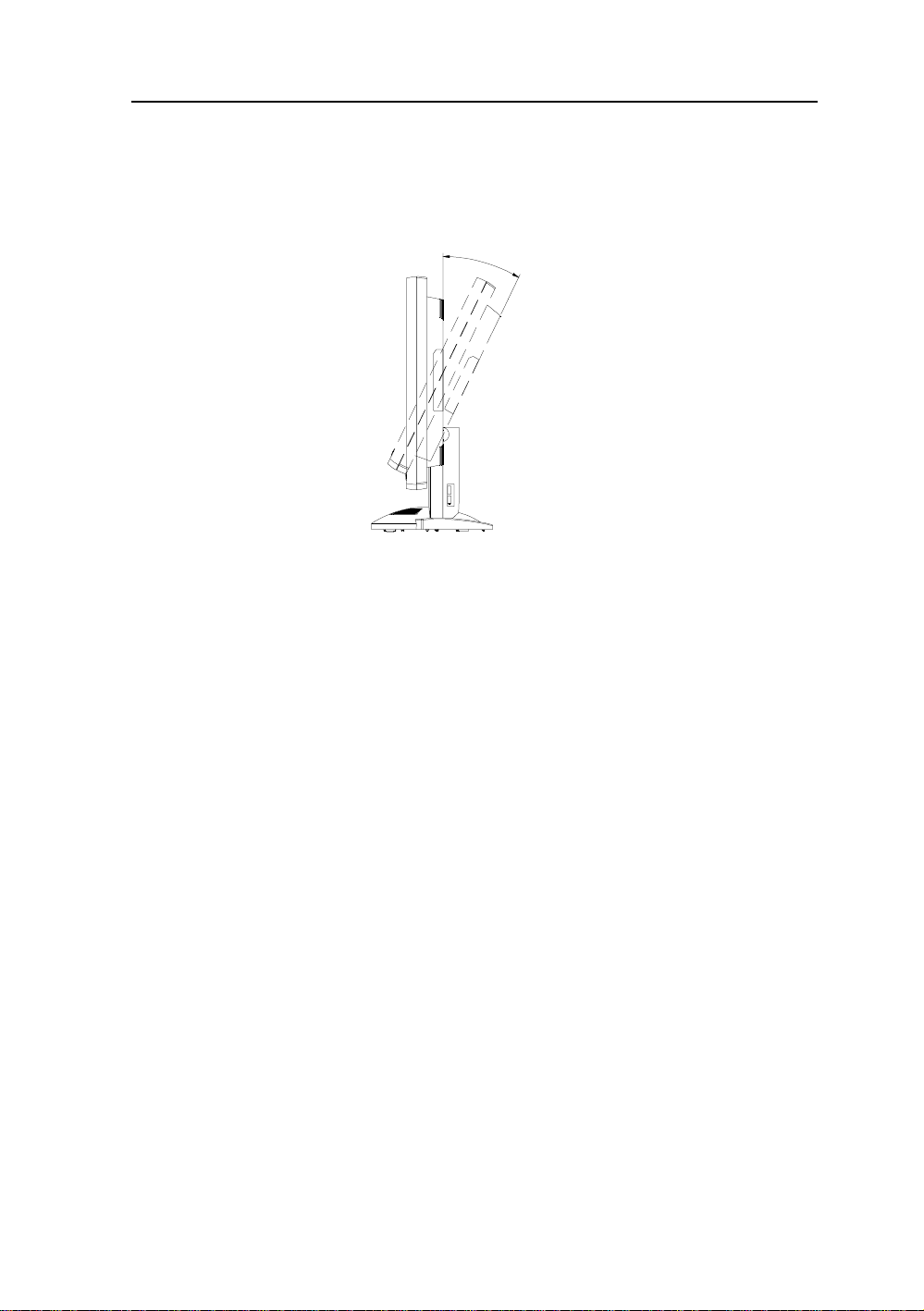
SCREEN POSITION ADJUSTMENT
In order to optimize the best viewing position, you can adjust the tilt of the monitor by using
both of your hands to hold the edges of the monitor as shown in the figure below. The monitor can be adjusted to 28 degrees up as indicated by arrow below.
2
8
°
Page 14

14 User’s Guide
SAFETY PRECAUTION
• A void placing the monitor , or any other heavy object, on the power cord to prevent fire or
electrical shock from damage to the power cord.
• Do not expose the monitor to rain, excessive moisture, or dust to avoid fire or shock hazard.
• Do not cover the slots or openings of the monitor for proper heat dissipation. Always put
the monitor in a place where there is adequate ventilation.
• Avoid placing the monitor against a bright background or where sunlight or other light
sources may reflect on the area of the monitor. Place the monitor just below eye level.
• Handle with care when transporting the monitor.
• Refrain from giving the shock or scratch to the screen, as screen is fragile.
CLEANING YOUR MONITOR
No specific liquid or chemical necessary when cleaning this LCD monitor
However, we suggest to clean the monitor with non-abrasive cloths and cleaning solutions
used in hospitals to clean similar equipment. We recommend using 70% Isopropyl alcohol
for the screen surface and warm water and a mild detergent for all other surfaces. Other
acceptable cleaning agents are listed below:
• 70% isopropyl alcohol
• 6% aqueous ammonia
• Cidex (2.4% glutaraldehyde solution)
• Sodium Hypochlorite (bleach) 10%
• “Green soap” USP
• 0.5% Chlorhexidine in 70% isopropyl alcohol
• Ovation
• Formula 409
• Fantastic
• W ex Cide
T o clean the screen, do not spray liquid cleaners directly on to the unit. S tand away Form the
monitor and spray cleaning solution onto a cloth. Without applying excessive pressure,
clean the screen with the slightly dampened rag.
Page 15

AMM170TK2/AMM17TK2/AMM18TK2/AMM19TK2/AMM19TK2(HB) 15
PRESET MODES
To reduce the need for adjustment for different modes, the monitor has default setting modes
that are most commonly used as given in the table below. If any of these display modes are
detected, the monitor automatically adjusts the picture size and centering. When none of the
mode is matched, the user can store their preferred modes in the user modes. The monitor is
capable of storing up to 7 user modes. The only condition to store as a user mode is the new
display information must have 1 KHz difference for horizontal frequency or 1 Hz for vertical
frequency or the sync signal polarities are different from the default modes.
M o de R e s olution (H x V) H. Fre q. (KHz) V. Fre q. (Hz)
1 640 x 350 31.5 70
2 640 x 350 37.9 85
3 640 x 400 31.5 70
4 640 x 400 37.9 85
5 720 x 350 31.5 70
6 720 x 400 31.5 70
7 7 20 x 400 37.9 85
8 640 x 480 31.5 60
9 640 x 480 37.9 72
10 640 x 480 37.5 75
11 640 x 480 43 .3 85
12 800 x 600 35.1 56
13 800 x 600 37.9 60
14 800 x 600 48.1 72
15 800 x 600 46.9 75
16 800 x 600 53.7 85
17 1024 x 768 35.5 43
18 1024 x 768 48.4 60
19 1024 x 768 56.5 70
20 1024 x 768 60 75
21 1024 x 768 68.7 85
22 1152 x 864 67.5 75
23 1280 x 960 60 60
24 1280x1024 63.9 60
25 1280x1024 79 75
Page 16

16 User’s Guide
POWER MANAGEMENT FUNCTION
The monitor is equipped with the power management function which automatically reduce the
power consumption when not in use in three power level modes.
• Stand-by Mode
The monitor goes into stand-by mode when the horizontal sync signal is off for about 10
seconds. In this mode, the screen goes off and the power LED blinks for 1 seconds On and
1 second Off. The screen is displayed after the horizontal sync signal is restored.
• Suspend Mode
The monitor goes into suspend mode when the vertical sync signal is off for about 10
seconds. The power consumption during this is less than 8 W. In this mode, the screen
goes off and the power LED blinks for 1 seconds On and 1 second Off. The screen is
displayed after the vertical sync signal is restored.
• Off Mode
The monitor goes into power-off mode when the vertical and horizontal sync signals are
off for about 10 seconds. In this mode, the screen goes off and the power LED blinks for 1
seconds On and 1 second Off. The screen is displayed after the vertical and horizontal
sync signals are restored.
Power Management System
The AMM170TK2, AMM17TK2, AMM18TK2, AMM19TK2 and AMM19TK2/HB Medical
Monitor complies with the VESA DPMS power management proposal. The VESA DPMS
proposal provides four phases of power-saving modes by detecting the horizontal sync
signal as shown in the table blow.
edoMrewoPtupnICD
)ylnorotinom(
nO.xamW53.xamW06neerGydaetS
ybdnatS.xamW5
dnepuS.xamW5.4.xamW6neerGgniknilB
ffO.xamW5.4.xamW6neerGgniknilB
.4.xamW6neerGgniknilB
rewoptupnICA
)retpadaCA.lcnI(
sutatSDEL
When the monitor is power saving mode or detects an incorrect timing, the screen will be
blank and power LED indicator will blink.
Page 17

AMM170TK2/AMM17TK2/AMM18TK2/AMM19TK2/AMM19TK2(HB) 17
DDC
T o make your installation easier , the monitor is able to Plug and Play with your system if your
system also supports DDC protocol. The DDC (Display Data Channel) is a communication
protocol through which the monitor automatically informs the host system about its
capabilities, for example, supported resolutions and corresponding timing. The monitor
supports DDC1 and DDC2B standard.
INSTALLATION
To install the monitor to your host system, please follow the steps as given below:
Steps
1 . Use the VGA cable that provides D-SUB 15-pin connector and connect to the
15-pin connector on the VGA controller card.
2 . Connect the DC power to the DC power connector on the monitor.
3. Connect one end of AC power cord into the AC Adapter and the other end to AC
power outlet.
4. Then turn the computer on and then the monitor.
5. If the monitor still does not function properly, please refer to the troubleshooting section
to diagnose the problem.
CONNECTING the POWER CORD
* Check first to make sure that the power cord you use is the correct type required for your area.
* This monitor has an universal AC adapter that allows operation in either AC 100 - 240 Vac
voltage area. No user-adjustment is required.
* Plug one end of the power cord to the AC adapter, plug another end to a proper AC outlet.
The cord set should have the appropriate safety approvals for the country in which the equipment
will be installed and marked HAR.
For 120 volt Applications, use only UL Listed deachable power cord with NEMA configuration
5-15P type (parallel blades) plug cap. For 240 volt applications use only UL Listed Detachable
power supply cord with NEMA configuration 6-15P type (tandem blades) plug cap.
Page 18

18 User’s Guide
Display for Video and Image Playback
Explains how to use our AMM17TK, AMM18TK, AMM19TK and AMM19TK/HB to play VCR,
view television, video game, or digital camera images. It also show you how to connect video
and other types of video equipment to the display.
Connecting with Video Equipment
You can connect many types of video equipment to the display. The equipment must have
either Super video (S-video) ports or Composite video ports. To install the monitor to your
video equipment, please follow the steps as given below:
Steps
1 . Make sure the video equipment has a Super video (S-video) or a Composite video connector.
2. Turn off the computer, display, and video equipment before any types of connection.
3. For composite video, plug one end of a BNC cable into the video out port on the video
equipment then connect the other end to the monitor video input port.
4 . For S-video, plug one end of the S-video cable into the video out port on the video equipment
then connect the other end to the monitor S-video input port.
5. Connect the DC power to the DC power connector on the monitor.
6. Connect one end of AC power cord into the AC Adapter and the other end to AC
power outlet.
7. Then turn the video equipment on and then the monitor.
Connecting to a Television Signal
The display doesn’t have a tuner . To view television on the display, you need to use either the
VCR or TV tuner card in your computer to change channels.
Video and Sound
This monitor doesn’t have speakers for sound. If you’re using the display to play a video or
view television images, you need to connect the speakers to your television or video equipment
for sound.
Page 19

AMM170TK2/AMM17TK2/AMM18TK2/AMM19TK2/AMM19TK2(HB) 19
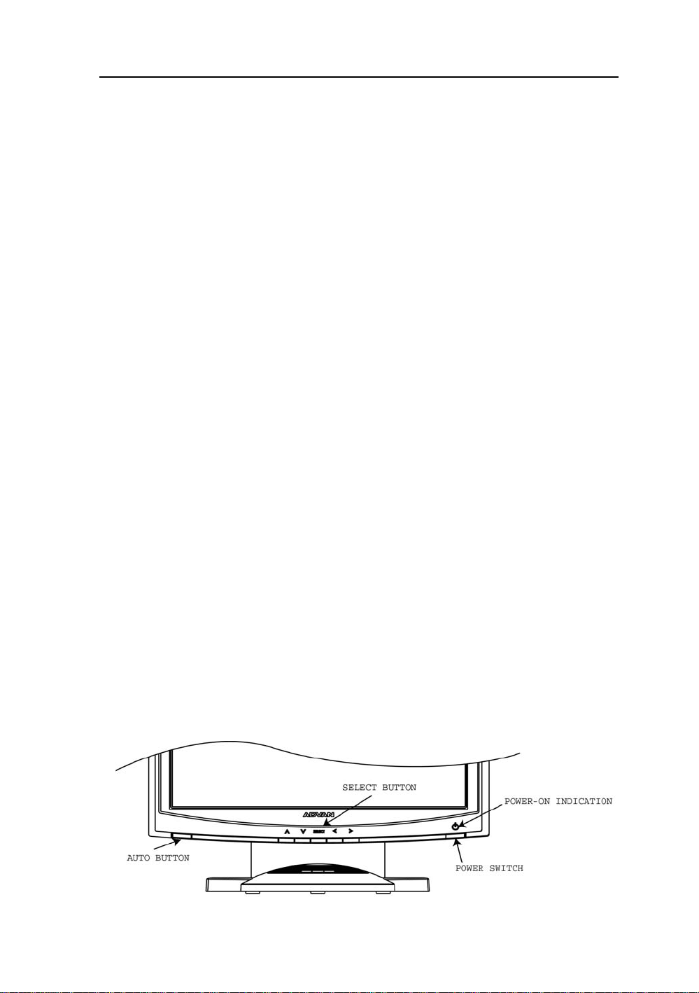
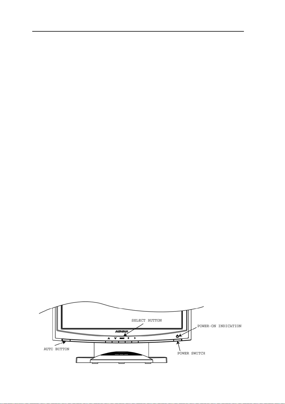
USER CONTROLS
Front Panel Controls
1. Power LED: Lights up to indicate the power is turned ON.
2. Power Switch: To turn ON or OFF the power.
3 . Up : To enter OSD menu then can use as moving forward in the OSD menu.
4. Down: To move backward in the OSD menu.
5. Select: Switch PC display to Video display and vice versa by one touch when OSD menu is not
activated.
Enter a sub menu or select a menu item.
6. Left: To increase the value of the parameter in the OSD you have selected for adjustment.
To increase the brightness directly when OSD menu is not activated.
7. Right: To decrease the value of the parameter in the OSD you have selected for adjustment.
To increase the brightness directly when OSD menu is not activated.
8. Auto Button: One touch Auto adjust (Hold 1 Sec.) or Exit OSD menu.
Standard OSD Operation
1. Press Up button to activate the OSD.
2. Use Select Up or Down keys to move up or down through the menu. The parameter will be highlighted
wehn selected.
3. Then use + or - to increase or decrease the value of the parameter, or make selection between different
options.
4. To quit the OSD screen at any time during the operation, press Auto button. If no keys are pressed for a
time period, the OSD automatically disappears.
Page 20

20 User’s Guide
OSD Scren Basic Section (VGA)
For OSD display, push “Up”. For selecting Icon, push “Up” or
“Down”
Push “Up” or “Down” button to select between
“Brightness” or “Contrast” then push “Select”
Use “Left” or “Right” button to adjust
Push “Up” or “Down” button to select between
“Horizontal” or “V ertical” then push “Select”
Use “Left” or “Right” button to adjust
Push “Up” or “Down” button to select between
“Frequency” or “Phase” then push “Select”
Use “Left” or “Right” button to adjust
Push “Up” or “Down” button to select between “OSD
Hor. Pos.”, “OSD Ver. Pos.”, “OSD Background”, or
“User Timeout” then push “Select”
Use “Left” or “Right” button to adjust
Push “Left” or “Right” to select Color Temp between
“Default”, “System 1”, “System 2”, “System 3”, or
“System 4” then push “Select”
If “System 1, 2, 3 or 4” were slected, push “Up” or
“Down” button to select between “Red”, “Green”, or
“Blue” then push “Select”
Use “Left” or “Right” button to adjust
Push “Up” or “Down” button to select between
“DPMS”, “Auto Source Select”, or “Freeze Frame”
then push “Select” Use “Left” or “Right” button to
adjust
Page 21

AMM170TK2/AMM17TK2/AMM18TK2/AMM19TK2/AMM19TK2(HB) 21
OSD Scren Basic Section (VGA)
For OSD display, push “Up”. For selecting Icon, push “Up” or
“Down”
Push the select button to execute the Zoom
function
Push the select button
Use “Left” or “Right” button to adjust
Push the select button to execute the Auto
Setup function or Push the select button to
execute Recall Factory Default
Push “Up” or “Down” button to select between
“Analog RGB”, “Digital RGB”, “Composite Video” or
“Super Video”
Use “Left” or “Right” to choose the correct mode then
push “Select” button
Push the select button to execute Information
Page 22

22 User’s Guide
OSD Scren Basic Section (DVI)
For OSD display, push “Up”. For selecting Icon, push “Up” or
“Down”
Push “Up” or “Down” button to select between
“Brightness” or “Contrast” then push “Select”
Use “Left” or “Right” button to adjust
Push “Left” or “Right” to select Color Temp between
“Default”, “System 1”, “System 2”, “System 3”, or
“System 4” then push “Select”
If “System 1, 2, 3 or 4” were slected, push “Up” or
“Down” button to select between “Red”, “Green”, or
“Blue” then push “Select”
Use “Left” or “Right” button to adjust
Push “Up” or “Down” button to select between “OSD
Hor. Pos.”, “OSD Ver. Pos.”, “OSD Background”, or
“User Timeout” then push “Select”
Use “Left” or “Right” button to adjust
Push “Up” or “Down” button to select between
“DPMS”, “Auto Source Select”, or “Freeze Frame”
then push “Select” Use “Left” or “Right” button to
adjust
Push the select button to execute the Zoom
function
Page 23

AMM170TK2/AMM17TK2/AMM18TK2/AMM19TK2/AMM19TK2(HB) 23
OSD Scren Basic Section (DVI)
For OSD display, push “Up”. For selecting Icon, push “Up” or
“Down”
Push “Up” or “Down” button to select between
Push the select button
Use “Left” or “Right” button to adjust
“Analog RGB”, “Digital RGB”, “Composite Video” or
“Super Video”
Use “Left” or “Right” to choose the correct mode then
push “Select” button
Push the select button to execute Recall
Factory Default
Push the select button to execute Information
Page 24

24 User’s Guide
OSD Scren Basic Section (C-V ideo or S-V ideo)
For OSD display, push “Up”. For selecting Icon, push “Up” or
“Down”
Push “Select” button then “Up” or “Down”
Push “Left” or “Right” button to adjust
Push “Up” or “Down” button to select between
“Horizontal” or “V ertical” then push “Select”
Use “Left” or “Right” button to adjust
Push “Up” or “Down” button to select between
“Brightness” or “Contrast” then push “Select”
Use “Left” or “Right” button to adjust
Push “Up” or “Down” button to select between “OSD
Hor. Pos.”, “OSD Ver. Pos.”, “OSD Background”, or
“User Timeout” then push “Select”
Use “Left” or “Right” button to adjust
Push “Left” or “Right” to select Color Temp
between “5000”, “6500”, 7300”, “9500”, or “User”
then push “Select”
If “User” were slected, push “Up” or “Down” button
to select between “Red”, “Green”, or “Blue” then
push “Select”
Use “Left” or “Right” button to adjust
Push “Up” or “Down” button to select between
“DPMS”, “Auto Source Select”, “Freeze Frame”, or
“ADC Calibration” then push “Select”
Use “Left” or “Right” button to adjust
Page 25

AMM170TK2/AMM17TK2/AMM18TK2/AMM19TK2/AMM19TK2(HB) 25
OSD Scren Basic Section (C-V ideo or S-V ideo)
For OSD display, push “Up”. For selecting Icon, push “Up” or
“Down”
Push the select button
Use “Left” or “Right” button to adjust
Push the select button
Use “Left” or “Right” button to adjust
Push the select button
Use “Left” or “Right” button to adjust
Push the select button to execute Recall
Factory Default
Push the select button to execute Information
Page 26

26 User’s Guide
OSD Function Description (Under Analog Display)
metInoitpircseDnoitcnuF
ssenthgirB.ssenthgirbehtesaercedroesaercnioT
tsartnoC.tsartnocehtesaercedroesaercn
ycneuqerF.)kcolctod(ycneuqerftsujdaoT
esahP.)esahp-kcolc(esahptsujdaoT
latnoziroH.thgirrotfelneercsehte
lacitreV.drawnwodrodrawpuneercsehtevomoT
soProHDSO.thgirrotfelunemDSOevomoT
soPreVDSO.drawnwodrodrawp
dnuorgkcaBDSO.tneculsnarTroeuqapOneewtebesoohC
tuoemiTresU.emitgniraeppaneercsDSOteS
loC ro3metsyS,2metsyS,1metsyS,tluaufeDneewtebesoohC
deR.deRecnalaB
eulB.
pmeTro
neerG.neerGecnalaB
SMPD.SMPDelbasiDroelbanE
ecruoSotuA
tceleS
emarFezeerFemarfez
ioT
vomoT
uunemDSOevomoT
.pmetroloc4metsyS
eulBecnalaB
eerfelbasiDroelbanE
noitcelesecruosotuaelbasidroelbanE
mooZnoitcnufni-moozelbanE
edoMelacS enoro,oitartcepsa,neercsllifneewtebedomelacsesooh
ecruoStupnI
tceleS
otuA -H,noitisoP-VtsujdayllacitamotualliwtsujdA-otuAehT
tsujdA
yrotcaFllaceR
tluafeD
noitamofnI tupnidna,etarhserfer,noitulosernonoitamrofniyalps
C
enoot
oedivrepusro,oedivetisopmoc
,kcolC,noitisoP
noCdna,esahP-kcolC
om
.tluafedyrotcafotteS
iD
.edom
.)tsujdAotuArofksidytiliturotin
,BGRlatigid,BGRgolananeewtebecruostupniesoohC
5tuobasekatssecorpelohweht,tsart
DCLdehcattaehtnielifnrettaptsetehtesuesaelP(.sdnoces
Page 27

AMM170TK2/AMM17TK2/AMM18TK2/AMM19TK2/AMM19TK2(HB) 27
OSD Function Description (Under Digital Display)
metInoitpircseDnoitcnuF
ssenthgirB.ssenthgirbehtesaercedroesaercnioT
tsartnoC.tsartnocehtesaercedroesaercn
latnoziroH.thgirrotfelneercsehtevomoT
lacitreV.drawnwodrodrawpuneercsehtevomoT
soProHDSO.thgirrotfelune
soPreVDSO.drawnwodrodrawpuunemDSOevomoT
dnuorgkcaBDSO.tneculsnarTroeuqapOneewtebesoohC
esU.emitgniraeppaneercsDSOteS
deR.deRecnalaB
neerG.neerGecnalaB
eulB.eulBecnalaB
SMPD.SMPDelbasiDroelbanE
tceleS
mooZnoitcnufni-moozelbanE
tuoemiTr
pmeTroloC ro3metsyS,2metsyS,1metsyS,tluaufeDneewtebesoohC
ecruoSotuA
emarFezeerFemarfezeerfelbasiDroelbanE
ioT
mDSOevomoT
.pmetroloc4metsyS
uaelbasidroelbanE
noitcelesecruosot
edoMelacS enoro,oitartcep
enoot
ecruoStupnI
tceleS
yrotcaFllaceR
tluafeD
noitamofnI tupnidna,etarhserfer,no
.edom
.tluafedyrotcafotteS
itulosernonoitamrofniyalpsiD
sa,neercsllifneewtebedomelacsesoohC
,BGRlatigid,BGRgolananeewtebecruostupniesoohC
oedivrepusro,oedivetisopmoc
Page 28

28 User’s Guide
OSD Function Description (Under C-Video or S-Video Display)
metInoitpircseDnoitcnuF
euH.leveleuhehtesaercedroesaercnioT
noitarutaS.levelnoitarutasehtesaercedroesaercnioT
ssenthgirB.ssenthgirbehtesaercedroesaercnioT
tsartnoC.tsartnocehtesaercedroesaercnioT
latnoziroH.thgirr
lacitreV.drawnwodrodrawpuneercsehtevomoT
soProHDSO.thgirrotfelunemDSOevomoT
soPreVDSO.drawnwodrodrawpuunemDSOevomoT
dnuorgkcaBDSO.tneculsnarTroeuqapOneewtebesoohC
tuoemiTresU.emitgniraeppaneercsDSOteS
pmeTroloC ro3metsyS,2metsyS,1metsyS,tluaufeDneewtebesoohC
deR.deRecnalaB
neerG.neerGecnalaB
eulB.eulBecnalaB
SMPD.SMPDelbasiDroelbanE
ecruoSotuA
tceleS
em
arFezeerF.emarfezeerfelbasiDroelbanE
mooZ.noitcnufni-moozelbanE
edoMelacSoediV ,edomelacs3:4,lamronneewtebedomelacsoedivesoohC
otfelneercsehtevomoT
.pmetroloc4metsyS
noitcelesecruosotuaelbasidroelbanE
.edomelacs9:61ro
ssenprahSoediV.ssenprahsoedivehtesaercedroesaercnioT
ecruoStupnI
tce
leS
yrotcaFllaceR
tluafeD
noitamofnI tupnidna,etarhserfer,noitulosernonoitamrofniyalpsiD
.edom
.tluafedyrotcafotteS
oedivrepusro,oedivetisopmoc
,BGRlatigid,BGRgolananeewtebecruostupniesoohC
Page 29

AMM170TK2/AMM17TK2/AMM18TK2/AMM19TK2/AMM19TK2(HB) 29
TROUBLESHOOTING
Before sending your LCD monitor for servicing, please check the troubleshooting list below
to see if you can self-diagnose the problem.
smelborPsutatStnerruCydemeR
NODEL
FFODEL
oN
erutciP
gniknil
BDEL
siyalpsiD
lamronbA
erutciP
alpsid
niegralootro
ezisy
•
•
•
•
hC
•
erutciPelbatsnU
•
•
retnec,gnissim
llamsootro,tfihs
•
•
nomdna
egami
uM
.rotinom
teserromumixam
.hctiwsrewopehtkcehC
ylreporpsidrocrewopCAfikcehC
.retpadaCAehtotdetcennoc
.rotinomfokcabehttadetcennoc
.gnimithserferlacitrevrehto
ottsartnocdnassenthgirbtsujda,DSOgnisU
.sgnittestluafedriehtot
ylreporpsielbaclangisoedivfikcehC
.NOsimetsysretupmocotrewopehtfikce
retpadascihpargfonoitacificepsehtfikcehC
ebyamhcihwecnailpmocnisiroti
.hctamsimycneuqerflangistupniehtgnisuac
yalpsidllitsfi,nottubputeSotuAgnisU
,KCOLCtsujdanehterutciplamronba
-VdnaNOITISOP-H,ESAHP-KCOLC
slangisdradnats-nonhtiwNOITISOP
.
neercs-llufgnissimfoesacni,DSOgnisU
ruoyninoituloserrehtotcelesesaelp,
ro)TN,89/59swodniW(metsySgnitarepO
gnitsujdaretfasdnoceswefaroftiawts
rognignahcerofebegamiehtfoeziseht
ehtFFOgnirewoprolangisehtgnitcennocsid
Page 30

30 User’s Guide
SPECIFICATION
2KT071MMA
lenaPDCL lenaPTFTroloChcni-71/mc2.34
epyTxirtaMevitcA
noituloseR )dednemmoceR(senil4201xstod0821
ctiPlexiPmm462.0
h
roloCyalpsiDsrolocnoillim61
emiTesnopseRsm52
enoTroloCenot652otpU
retliFroloCepytepirtslacitr
gnihsiniFecaFdetaoCdraHeralG-itnA
elgnAgniweiV)01=>RC(V°071H°071
oediV latigiD)kniLlenaP(SDMT&BGRgola
langiStupnI
cnyScnysdetarapesp-pV0.5~5.2
)golanA(ecnadepmItupnImhO57-oediV
etisopmoCoediV-S,oediV-C
cnyS
latigiD -BSMtib42lexipelgnis,reviecerSDMTlennahc3
ycneuqerFgninnacS
latnoziroHzHk86~03
lacitreV otpudnaedom867x4201tazH58otPU(zH58~65
eziSyalpsiD
VxH )mm33.072
selacSyarG,oitdaRtsartnoC,ssenthgirB
ssenthgirBdradnatS,2m/dc052
oitaRtsartnoC.pyT1:
selacSyarGspets652otpU
rotcennoCtupnIlangiS
oediV oediV-S,CSTN,IVDlatigiD,nip51-51DH
neercshcuoT)lanoitp
tnemnorivnEerutarepmeT
erutarepmeTgnitarepO)C°04-°01(F°401~°05
ytidimuHgnitarepO )noitasnedno
erusserPcirehpsomtAgnitarepOaPh0601~007
ecruoSrewoP
rotinoMyalpsiDV21CD
retpadA-CA lamroN,
snoitalugeR
CMEdnaytefaS 1XPI,EC,2-1-10606NE,1-10606NE,1-1062LU
tenibaC
dnatSpotkseD )D(hcni5.9x)H(hcni8.71x)W(hcni5.71
tnuoMeerF )D(hcni3x)H(hcni52.41x)W(hcni5.71
thgieW
dnatSpotkseD)gK3.9(.bl
tnuoMeerF)gK3.7(.bl61
esaBtliT
eludoMlanoitpO
* All contents are subject to change without notice.
* Touch Screen Model doesn’t include the Video-in (C-Video, S-Video) function.
* Surface Wave Touchscreen model -TEW and Resistive Touchscreen model -TE
evBGR
nap-pV7.0
1xzHM561
mhOk1-cnyS
TFTBGRdengila
)4201x0821tazH57
xmm29.733("6.01x"3.31
005
O(9-BD232-SR
ctuohtiw(HR%57~03
)noitarepO
W(mm054
6.02
pU°82nwoD°0
lenaPhcuoT
noitpotuohtiW(W06V042~001CA
PIhtiwecnailpmocsirotinomehT(
)1X
)D(mm542x)H(mm554x)
)D(mm67x)H(mm263x)W(mm054
Page 31

AMM170TK2/AMM17TK2/AMM18TK2/AMM19TK2/AMM19TK2(HB) 31
SPECIFICATION
2KT71MMA
lenaPDCL lenaPTFTroloChcni-4.71/mc2.44
epyTxirtaMevitcA
noituloseR )dednemmoceR(senil4201xstod0821
hctiPlexiPmm72.0
roloCyalpsiDsrolocnoillim61
emiTesnopseRsm52
enoTroloCenot652otpU
retliFroloCepytepirtslacitr
gnihsiniFecaFdetaoCdraHeralG-itnA
elgnAgniweiV)01=>RC(V°061H°061
oediV latigiD)kniLlenaP(SDMT&BGRgola
langiStupnI
cnyScnysdetarapesp-pV0.5~5.2
)golanA(ecnadepmItupnImhO57-oediV
etisopmoCoediV-S,oediV-C
cnyS
latigiD -BSMtib42lexipelgnis,reviecerSDMTlennahc3
ycneuqerFgninnacS
latnoziroHzHk86~03
lacitreV otpudnaedom867x4201tazH58otPU(zH58~65
eziSyalpsiD
VxH )mm84.672
selacSyarG,oitdaRtsartnoC,ssenthgirB
ssenthgirBdradnatS,2m/dc022
oitaRtsartnoC.pyT1:0
selacSyarGspets652otpU
rotcennoCtupnIlangiS
oediV oediV-S,CSTN,IVDlatigiD,nip51-51DH
neercshcuoT)lanoitpO
tnemnorivnEerutarepmeT
erutarepmeTgnitarepO)C°04-°01(F°401~°05
ytidimuHgnitarepO )noitasnednoc
erusserPcirehpsomtAgnitarepOaPh0601~007
ecruoSrewoP
rotinoMyalpsiDV21CD
retpadA-CA lamroN,n
snoitalugeR
CMEdnaytefaS 1XPI,EC,2-1-10606NE,1-10606NE,1-1062LU
tenibaC
dnatSpotkseD )D(hcni5.9x)H(hcni8.71x)W(hcni5.71
tnuoMeerF )D(hcni3x)H(hcni52.41x)W(hcni5.71
thgieW
dnatSpotkseD)gK3.9(.bl6
tnuoMeerF)gK3.7(.bl61
esaBtliT
eludoMlanoitpO
* All contents are subject to change without notice.
* Touch Screen Model doesn’t include the Video-in (C-Video, S-Video) function.
* Surface Wave Touchscreen model -TEW and Resistive Touchscreen model -TE
evBGR
nap-pV7.0
1xzHM561
mhOk1-cnyS
TFTBGRdengila
)4201x0821tazH57
xmm0.543("9.01x"6.31
04
(9-BD232-SR
tuohtiw(HR%57~03
)noitarepO
(mm054
.02
pU°82nwoD°0
lenaPhcuoT
oitpotuohtiW(W06V042~001CA
IhtiwecnailpmocsirotinomehT(
)1XP
)D(mm542x)H(mm554x)W
)D(mm67x)H(mm263x)W(mm054
Page 32

32 User’s Guide
SPECIFICATION
2KT81MMA
lenaPDCLenaPTFTroloChcni-1.81/mc64
epyTxirtaMevitcA
noituloseR )dednemmoceR(senil4201xstod0821
PlexiPmm82.0
hcti
roloCyalpsiDsrolocnoillim61
emiTesnopseRsm04
enoTroloCenot652otpU
retliFroloCepytepirtslacitrevBG
gnihsiniFecaFdetaoCdraHeralG-itnA
elgnAgniweiV)01=>RC(V°061H°061
oediV latigiD)kniLlenaP(SDMT&BGRgolanap-
langiStupnI
cnyScnysdetarapesp-pV0.5~5.2
)golanA(ecnadepmItupnImhO57-oediV
opmoCoediV-S,oediV-C
latigiD -BSMtib42lexipelgnis,reviecerSDMTlennahc3
oziroHzHk86~03
VxH )mm782xmm953(
yarGspets652otpU
oediV oediV-S,CSTN,IVDlatigiD,nip51-9BD
tkseD)gK4.01(.bl8.22
cnySetis
ycneuqerFgninnacS
latn
lacitreV otpudnaedom867x4201tazH58otPU(zH58~65
eziSyalpsiD
ssenthgirBdradnatS,2m/dc002
oitaRtsartnoC.pyT1:052
selacS
rotcennoCtupnIlangiS
neercshcuoT)lanoitpO(9-BD232-
tnemnorivnEerutarepmeT
erutarepmeTgnitarepO)C°04-°01(F°401~°05
ytidimuHgnitarepO )noitasnednoctuohtiw(H
erusserPcirehpsomtAgnitarepOaPh0601~007
ecruoSrewoP
rotinoMyalpsiDV21CD
retpadA-CA).xaM(W06V042~001C
snoitalugeR
CMEdnaytefaS 1XPI,EC,2-1-10606NE,1-10606NE,1-1062LU
tenibaC
dnatSpotkseD )D(hcni5.9x)H(hcni8.71x)W(hcni5.71
tnuoMeerF )D(hcni3x)H(hcni52.41x)W(hcni5.71
thgieW
dnatSpo
tnuoMeerF)gK2.8(.bl1.81
esaBtliT
eludoMlanoitpO
* All contents are subject to change without notice.
* Touch Screen Model doesn’t include the Video-in (C-Video, S-Video) function.
* Surface Wave Touchscreen model -TEW and Resistive Touchscreen model -TE
R
pV7.0
1xzHM561
mhOk1-cnyS
TFTBGRdengila
)4201x0821tazH57
"3.11x"31.41
selacSyarG,oitdaRtsartnoC,ssenthgirB
SR
R%57~03
A
pU°82nwoD°0
lenaPhcuoT
)1XPIhtiwecnailpmocsirotinomehT(
Page 33

AMM170TK2/AMM17TK2/AMM18TK2/AMM19TK2/AMM19TK2(HB) 33
SPECIFICATION
2KT91MMA
lenaPDCLenaPTFTroloChcni-91/mc84
epyTxirtaMevitcA
noituloseR ).xaM(.zH57@senil4201xstod0821
hctiPle
xiPmm492.0
roloCyalpsiDsrolocnoillim61
emiTesnopseRffoTotnoTsm01;gvasm52
enoTroloCenot652otpU
retliFroloCepyte
gnihsiniFecaFdetaoCdraHeralG-itnA
elgnAgniweiV)01=>RC(V°071H°071
oediV latigiD)kniLlenaP(S
langiStupnI
cnyScnysdetarapesp-pV0.5~5.2
)golanA(ecnadepmItupnImhO57-oediV
cnySetisopmoCoediV-S,oediV-C
latigiD -BSMtib42lexipelgnis,reviecerSDMTlennahc3
ycneuq
erFgninnacS
latnoziroHzHk89.97~74.13
lacitreV otpudnaedom867x4201tazH58otPU(zH58~05
eziSya
lpsiD
VxH)mm103xmm673("9.11x"8.41
selacSyarG,oitdaRtsartnoC,ssenthgirB
ssenthgirBdradnatS,2m/dc052
oitaRtsa
rtnoC.pyT1:007
selacSyarGspets652otpU
rotcennoCtupnIlangiS
oediV oediV-S,CSTN,IVDlatigiD,nip51-51DH
neercshc
uoT)lanoitpO(9-BD232-SR
tnemnorivnEerutarepmeT
erutarepmeTgnitarepO)C°04-°01(F°401~°05
ytidimuHgnitarepO )n
erusserPcirehpsomtAgnitarepOaPh0601~007
ecruoSrewoP
rotinoMyalpsiDV51CD
retpadA
-CAV042~001CA
snoitalugeR
CMEdnaytefaS 1XPI,EC,2-1-10606NE,1-10606NE,1-10606LU
tenibaC
dnatSpotkseD )D(hcni5.9x)H(hcni8.71x)W(hcni5.71
tnuoMeerF )D(hcni3x)H(hcn
thgieW
dnatSpotkseD)gK6.8(.bl91
tnuoMeerF)gK3.7(.bl61
esaBtliT
eludoMlanoitpO
* All contents are subject to change without notice.
* Touch Screen Model doesn’t include the Video-in (C-Video, S-Video) function.
* Surface Wave Touchscreen model -TEW and Resistive Touchscreen model -TE
pirtslacitrevBGR
1xzHM561
mhO
k1-cnyS
TFTBGRdengila
)4201x0821tazH57
csirotinomehT(
)ylnoledom
i52.41x)W(hcni5.71
pU°82nwoD°0
l
enaPhcuoT
DMT&BGRgolanap-pV7.0
oitasnednoctuohtiw(HR%57~03
hcuotenon,1XPIhtiwecnailpmo
Page 34

34 User’s Guide
SPECIFICATION
BH/2KT91MMA
lenaPDCLenaPTFTroloChcni-91/mc84
epyTxirtaMevitcA
noituloseR )dednemmoceR(senil4201xstod0821
hct
iPlexiPmm492.0
roloCyalpsiDsrolocnoillim61
emiTesnopseRxamsm8.gvasm21
enoTroloCenot652otpU
retliFroloCepytepir
gnihsiniFecaFdetaoCdraHeralG-itnA
elgnAgniweiV)01=>RC(V°871H°871
oediV latigiD)kniLlenaP(SDMT
langiStupnI
cnyScnysdetarapesp-pV0.5~5.2
)golanA(ecnadepmItupnImhO57-oediV
cnySetisopmoCoediV-S,oediV-C
latigiD -BSMtib42lexipelgnis,reviecerSDMTlennahc3
gninnacS
latnoziroHzHk8.97~74.13
lacitreV otpudnaedom867x4201tazH58otPU(zH58~05
D
VxH)mm103xmm673("9.11x"8.41
ssenthgirBxaM,2m/dc054
selacSyarGspets652otpU
oediV oediV-S,CSTN,IVDlatigiD,nip51-51DH
neercshcuoT)lanoit
retpadA-CAV042~00
snoitalugeR
tenibaC
tnuoMeerF )D(hcni3x)H(hcni52.41x)W
thgieW
tnuoMeerF)gK3.7(.bl61
esaBtliT
ycneuqerF
eziSyalpsi
oitaRtsartnoC.pyT1
rotcennoCtupnIlangiS
tnemnorivnEerutarepmeT
erutarepmeTgnitarepO)C°04-°01(F°401~°05
ytidimuHgnitarepO )noitasnedn
erusserPcirehpsomtAgnitarepOaPh0601~007
ecruoSrewoP
rotinoMyalpsiDV51CD
CMEdnaytefaS 1XPI,EC,2-1-10606NE,1-10606NE,1-10606LU
dnatSpotkseD )D(hcni5.9x)H(hcni8.71x)W(hcni5.71
dnatSpotkseD)gK6.8(.bl91
eludoMlanoitpO
cnyS
selacSyarG,oitdaRtsartnoC,ssenthgirB
:009
1CA
mehT(
* All contents are subject to change without notice.
* Touch Screen Model doesn’t include the Video-in (C-Video, S-Video) function.
* Surface Wave Touchscreen model -TEW and Resistive Touchscreen model -TE
tslacitrevBGR
1xzHM561
)ylnoledom
(hcni5.71
lenaPhcuoT
&BGRgolanap-pV7.0
mhOk1-
TFTBGRdengila
)4201x0821tazH57
pO(9-BD232-SR
octuohtiw(HR%57~03
pU°82nwoD°0
hcuotenon,1XPIhtiwecnailpmocsirotino
Page 35

AMM170TK2/AMM17TK2/AMM18TK2/AMM19TK2/AMM19TK2(HB) 35
51LJ
Medical Equipment
E215822
This monitor is intended for use in Health Care Facilities model AMM170TK2/
AMM17TK2/AMM18TK2/AMM19TK2/AMM19TK2(HB)
Equipment is not suitable for use in the presence of flammable anesthetic mixture
with air or with oxygen or nitrous oxide.
No user serviceable parts inside, ask qualified personnel when accessing inside.
For disposal of waste product, follow the requirement of local code.
Electrical input rating: 15V DC 6A
Classification
T ype of protection against electric shock: Class I Equipment.
Degree of protection against the ingress of water: IPX1 (none touch model) IP:X0 (touch
model)
Mode of operation: Continuous
This monitor has been tested to comply with IEC/EN 60601-1, IEC/EN60601-1-2 and is
certified by UL to medical standard UL60601-1(UL/cUL Mark).
Because many medical offices are located in residential areas, this monitor, in addition to the
medical requirements, has also been tested and found to comply with the limits for FCC Class
B computing devices in a typically configured system. It is the system integrator or
configurer’s responsibility to test and ensure that the entire system complies with applicable
EMC laws.
Environmental conditions for transport and storage:
- Temperature range within -4° to 140° F (-20° to 60° C)
- Relative humidity range within 10% to 90%
- Atmospheric pressure range within 500 to 1060 hPa.
Page 36

36 User’s Guide
Page 37

AMM170TK2/AMM17TK2/AMM18TK2/AMM19TK2/AMM19TK2(HB) 37
Page 38

38 User’s Guide
Page 39

AMM170TK2/AMM17TK2/AMM18TK2/AMM19TK2/AMM19TK2(HB) 39
* AMM170TK2, AMM17TK2, AMM18TK2, AMM19TK2(HB)
Page 40

40 User’s Guide
Connectors
DC Input
Connector Jack Power Input
The SCD-014-1-A (SHIUA CHYUAN) or equivalent.
noitpircseDniP
CDV51+1
DNG2
Video Input
15 pin D-subminiature connector.
The vedor P/N is DHSB-15 FRF7(LEOCO) or equivalent.
noitpircseDniPnoitpircseDniP
oediVdeR1CN9
oediVneerG2noCAGV01
oediVeulB3CN11
CN4)2/1CDD(ADS21
dnuorGcigoL5cnys-H31
VdeR6cnys-V41
dnuorGoedi
dnuorGoediVneerG7)B2CDD(LCS51
dnuorGoediVeulB8
24 pin DVI-D connector.
DDWG or equivalent connector.
niPtnemngissAlangiSniPtnemngissAlangiSniPtnemngissAlangiS
1-2ataD.S.D.M.T9-1ataD.S.D.M.T71-0ataD.S.D.M.T
2+2ataD.S
34/2ataD.S.D.M.T
4-4
5+4ataD.S.D.M.T31+3ataD.S.D.M.T22+5ataD.S.D.M.T
6kcolCCDD41rewoPV5+22kco
7ataDCDD51)V5+rof(dnuorG32+kcolC.S.D.M.T
8tcennoCoN61tceteDgulPtoH42-kcolC.S.D.M.T
.D.M.T01+1ataD.S.D.M.T81+0ataD.S.D.M.T
dleihS
T ouch Port
9Pin D-subminiature connector.
DCD1RSD6
DXR2STR7
DXT3STC8
RTD4CNIR9
cigoL
dnuorG
113/1ataD.S.D.M.T
ataD.S.D.M.T21-3ataD.S.D.M.T02-5ataD.S.D.M.T
noitpircseDniPnoitpircseDniP
dleihS
5
915/0ataD.S.D.M.T
dleihS
lC.S.D.M.T
dleihS
Page 41

AMM170TK2/AMM17TK2/AMM18TK2/AMM19TK2/AMM19TK2(HB) 41
Description of Warranty
Advan warrants that the goods the goods sold hereunder will be free of defects in materials
and workmanship, and such goods will substantially conform to the specifications furnished
by Advan, and to any drawings or specifications furnished to Advan by the Buyer if
approved by Advan. This warranty shall be effective only if Advan receives notice of such
defect or nonconformance during the period of the warranty . Advan sole and exclusive the
Advan product(s) with refurbished units provide a credit to buyer in the amount of the
purchase
price.
Commencement and Duration of Warranty
The warranty period begins on the date of shipment from Advan. The goods sold hereunder
are warranted for a period of 18 months from date of shipment unless otherwise agreed to by
Buyer and Advan. No extension of the warranty will be given during the time the goods are
in Advan possession.
Place of Repair or Replacement
In order to obtain service under this warranty, Buyer must notify Advan of the defect before
expiration on the warranty period, and request a “Return Material Authorization Number .” If
the configuration has been modified in any manner, the product must be returned to its
original configuration before any warranty service will be perfomed by Advan. No goods are
to be returned to Advan without prior authorization. Buyer will be responsible for packaging
and shipping the defective goods to the Advan Service Facility with shipping charges
prepaid.
Limitation of Warranty
Monitor:
For 18 months after the date of purchase, ADVAN or its Authorized Service Centers, will repair
or replace if defective in material or workmanship. This Limited Warranty does not include
cleaning, or damage caused by accident, neglect, misuse or improper installation or operation,
any damage caused from service, maintenance, modifications or tampering by anyone other
than an ADVAN Authorized Service Representative, or by the use of supplies, consumable
items and conditions beyond the control of ADVAN, such as common carrier provided equipment
and/or facilities, operation of ADVAN product in excess of the specifications or with the Serial
Number or Rating label removed.
*T ouch Screen:
For one year after the date of purchase, ADVAN or its Authorized Service Centers, will repair
or replace if defective in material or workmanship. This Limited W arranty does not include
cleaning, or damage caused by accident, neglect, misuse or improper installation or operation, any damage caused from service, maintenance, modifications or tampering by anyone
other than an ADVAN Authorized Service Representative, or by the use of supplies, consumable items and conditions beyond the control of ADVAN, such as common carrier provided
equipment and/or facilities, operation of ADVAN product in excess of the specifications or
with the Serial Number or Rating label removed.
Page 42

42 User’s Guide
ADV AN DISCLAIMS ALL OTHER W ARRANTIES EXPRESS OR IMPLIED INCLUDING,
WITHOUT LIMIT A TION, ANY IMPLIED W ARRANTIES OF MERCHANT ABILITY OR
FITNESS FOR P ARTICULAR PURPOSE, EXCEPT TO THE EXTENT THA T ANY W ARRANTIES IMPLIED BY LA W CANNOT BE V ALIDL Y W AIVED.
No oral or written information or advice given by ADVAN, its authorized service center,
distributors, dealers, agents or employees, shall create another warranty or modify this
warranty . This warranty states ADVAN’ s entire liability and your exclusive remedy against
ADVAN for any failure of the ADVAN’ s product to operate properly .
Neither ADVAN nor anyone else involved in the development, production, or delivery of this
product shall be liable for any indirect, incidental, special consequential, exemplary, or
punitive damages, including lost profits, arising from the use of or inability to consequential
or incidental damages, the above limitation may not apply to you.
This Limited Warranty gives you special legal rights and you may also have other right,
which vary from State to State.
Installation
Advan makes no warranty with respect to any installation of Advan’s product(s)
by Advan, any authorized dealer, or any other person.
T echnical Assistance
For technical assistance please call (510)490-1005 between 8:00 a.m. and 5:00 p.m. PST ,
Monday through Friday or email to support@mail.advancorp.com with a description of your
technical issues.
Service
If your Medical Monitor needs service, call Advan Customer Service at
(510)490-1005 between 7:00 a.m and 4:00 p.m PST , Monday through
Friday or fax to (510)490-1151. Y ou will need the unit’ s serial number and a
brief description of the problem and where unit were purchased to receive a RMA number.
If a service is required please return the product for service using the original shipping
container with the RMA number included in package on the outside of the box.
In order to protect ADVAN employees form potential health hazards, ADVAN requir es that
the RMA product be disinfected befor e returning to ADV AN for service. Any product not
cleaned prior to shipment will be returned to the customer .
Note: Returns will not be accepted without an assigned RMA number.
In-transit damage is not covered by warranty. We suggest you always insure your shipment.
Advan will only pay for the return shipment by surface transportation. It is the responsibility
of the sender to prepay transportation charges.
Page 43

AMM170TK2/AMM17TK2/AMM18TK2/AMM19TK2/AMM19TK2(HB) 43
T ounchscreen User's Manual (AMM170TK2-TE/AMM17TK2-TE/
AMM18TK2-TE/AMM19TK2-TE/AMM19TK2(HB)-TE or
AMM170TK2-TEW/AMM17TK2-TEW/AMM18TK-TEW/AMM19TK2-
TEW/AMM19TK2(HB)-TEW)
Quick Start
1.Connect Power Code and VGA Cable of LCD Monitor.
2.Connect T ouchscreen DB9 male RS-232 cable.
3.Turn the LCD display Power ON.
4.Adjust the tilt of LCD Monitor.
5.Adjust the Picture of LCD Monitor.
6.Install driver software of T ouchscreen (See "Driver software" for details).
7.Adjust the calibration of T ouchscreen (See "Driver software" for details).
Introduction
The ELO IntelliT ouch T ouchscreen system consists of a touchscreen and an
electronic touchscreen controller. The touchscreen may be a flat, spherical, or
cylindrical and is installed over the face of the LCD. The touchscreen controller
installed inside of theLCD.
The IntelliT ouch T ouchscr een
The IntelliT ouch surface wave touchscreen consists of a glass panel molded to the
precise shape of a display's face. A scratch-resistant, hard-coated plastic cover
sheet may be clear for best image clarity or have an antiglare finish.
The IntelliT ouch Controller
The IntelliT ouch controllers provide the drive signal for touchscreen, convert the
received analogue signals into digital touch coordinates, and send these
coordinates to the computer.
Page 44

44 User’s Guide
T ouchmonitor installation
Cable Connection
1. Connect and test LCD as a video display only .
2. Plug the DB9 male into the DB9 female connector labled "TOUCHSCREEN"
on the back of the LCD Monitor.
Driver software
ELO provide driver programs for the DOS, Windows 3.1, Windows 95/98,
Windows NT , Windows 2000, W indows XP , OS/2, and Macintosh systems.
Additional drivers may be available for other system. Contact ELO for details.
Installing Driver software for W indows / Windows NT
1. Shutdown Windows or Windows NT and turn of f your computer.
2. Install touchscreen hardware as described in the "Quick start" or "T ouchmonitor
installation".
3. Start your computer .
4. Insert the Windows or Windows NT driver disk into diver A or B.
5. Browse for "setup.exe" in the directory to which you extracted the driver files.
6. T ype "setup.exe" in the space provided and press Enter .
7. The touchscreen setup wizard will appear . Y ou will need to select serial port,
type of touchscreen controller, and language.
8. Complete the setup program.
9. Shutdown and restart windows NT .
10. Click the start button, then click control panel.
11. Double-click touchscreen control panel.
12. Click the calibrate button and touch each of the three targets as they appear
on the screen.
Contacting ELO
www .elotouch.com
ELO T ouchsystems INC.
6500 Kaiser Drive Fremont,
CA 94554 USA
Page 45

AMM170TK2/AMM17TK2/AMM18TK2/AMM19TK2/AMM19TK2(HB) 45
 Loading...