

Page 1
Elo EntuitiveTouchmonitor
User Guide
For 18.1" LCD DesktopTouchmonitors
1825L/1827L Series
Revision B
Page 2
Elo Entuitive Touchmonitor
User Guide
18.1" LCD Desktop Touch mo nito r
1825L/1827L Series
Revision B
P/N 008563
Elo TouchSystems, Inc.
1-800-ELOTOUCH
www.elotouch.com
Page 3

Copyright © 2002 Elo TouchSystems Inc. All Rights Reserved.
No part of this publication may be reproduced, transmitted, transcribed, stored in a retrieval system,
or translated into any language or computer language, in any form or by any means, includi ng, but not
limited to, electronic, magnetic, optical, chemical, manual, or otherwise without prior written
permis s ion of Elo Touch Systems.
Disclaimer
The information in this document is subject to change without notice. Elo TouchSystems makes no
representations or warranties with respect to the contents hereof, and specifically disclaims any
implied warranties o f merchantab ility or fitness for a particular pu rpose. Elo TouchSystems rese rves
the right to revise this publicati on and to make changes from time to time in the content hereof
without obliga t ion of Elo TouchSystems to notify any pe r son of such revis i o ns or chang es.
Trademark Acknowledgments
IntelliTouch, iTouch, SecureTouch, AccuTouch, Entuitive, and MonitorMouse are trademarks of Elo
TouchSystems Inc.
Other product names mentioned herein may be trademarks or registered trademarks of their
respective companies. Elo TouchSystems claims no interest in trademarks other than its own.
iii
Page 4

iv
Page 5

Table of Contents
Chapter 1
Introduction 1
Precautions . . . . . . . . . . . . . . . . . . . . 1
About the Product . . . . . . . . . . . . . . . . . 1
Chapter 2
Installation and Setup 3
Unpacking Your Touchmonitor. . . . . . . . . . . 3
Product Overview . . . . . . . . . . . . . . . . . 4
Main Unit . . . . . . . . . . . . . . . . . . . . 4
Rear View . . . . . . . . . . . . . . . . . . . 4
Side View. . . . . . . . . . . . . . . . . . . . 5
Base Bottom View . . . . . . . . . . . . . . . 5
Touch Interface Connecti on . . . . . . . . . . . . 6
Serial or USB Connection . . . . . . . . . . . 6
STEP 1-Routing the Cables . . . . . . . . . 7
STEP 2-Connecting the Vid eo Ca ble . . . . 8
STEP 3-Connecting the Serial or USB
Touchscreen Cable . . . . . . . . . . . . . 9
STEP 4-Connecting the SpeakerCabl e . 10
STEP 5-Connecti ng the Power Cable. . . 11
Optimizing the LCD Display . . . . . . . . . . . 12
VESA Mount on YourTouchmonitor. . . . . . . 12
Accessing the VESA Mounting Interface. . . 13
Mounting the Base . . . . . . . . . . . . . . . 13
Installing the Driver Software . . . . . . . . . . 14
Installing the Serial Touch Driver. . . . . . . 15
Installin g the Serial T o uch Driver for Windo ws
XP, 2000, Me, 95/98 and NT 4.0 . . . . . 15
Installin g the Seri al Touch Driv er for MS-DOS
and Win d ow s 3.1 . . . . . . . . . . . . . 16
Installi ng the USB Tou ch Driver . . . . . . . 17
Installing the USB Touch Driver for Windows
XP, 2000, Me and 98 . . . . . . . . . . . 17
Chapter 3
Operation 19
About Tou chmonitor Adjustments. . . . . . . . 19
Using the On-Screen Display (OSD) Menus . . 19
Side Bezel Buttons . . . . . . . . . . . . . . . 20
OSD Menu Function . . . . . . . . . . . . . . 21
Auto Adjustment . . . . . . . . . . . . . . . . 22
Chapter 4
Troubleshooting 23
Solutions to Common Problems . . . . . . . . 23
Appendix A
Native Resolution 25
Appendix B
Touchmonitor Safety 27
Care and Handling of Your T ouchmonitor. . . . 28
Appendix C
T echnical Specifications 29
Compatible Vi deoModes . . . . . . . . . . . . 29
Touchmonitor Specifications . . . . . . . . . . 30
18.1" LCD Touchmonitor (ET182XL-XXWB-X)
Dimensions . . . . . . . . . . . . . . . . . . 34
Regulatory Information 37
Warranty 41
Index
43
v
Page 6

vi
Page 7

Congratulati ons on your purchase of an Elo TouchSystems Entuitive
touchmonitor. Your new touchmonitor combines the reliable perf ormance of
Elo’s touch technolo gy with the latest advances in LCD display design. This
combination of featur es creates a natural flow of information between a user
and your touchmonitor.
Precautions
C HAPTER
1
C
HAPTER
1
I
NTRODUCTION
Follow all warnings, precautions and maintenance as recommended in this
user’s manual to maximize the life of your unit. See Appendix B for more
information on touchmon itor safety.
Abou t the Pr oduct
Your LCD Desktop Touchmonitor is a 18.1” SXGA TFT color display with the
following feature s:
• Direct analog RGB or Digital RGB input
•18.1” diagonal screen size
• 16.7 million displayable colors
•1280 x 1024 resolution
• SXGA/XGA/SVGA/VGA/VESA/Mac c ompatible
•30kHz~80kHz horizontal scan
• 56~75Hz refresh rate
1-1
Page 8

• Auto adjustment capability
• High quality full screen re-scaling
• Multilingual OSD menus in six languages: English, French, German,
Spanish, Italian and Japanese
• Serial or USB touch interface (USB requires Windows 98, 2000, Me and
XP.)
• Built in speakers with volume, treble, bass and balance control through OSD
• Patented touch technology of Elo TouchSystems
• Power saving mode
o
• Stand with minimum 95
angle of tilt.
• Cable management device
• VESA flat panel monitor physical mounting interface (Both of 75 & 100mm)
• OSD and Power button lockouts
• Wall mountable with existing stand
• M5 threaded holes on bottom of stand for securing to desk or other surface,
i.e. table top
•
Cable stain reliefs for all cables
For full Product Specifications refer to Appendix C.
1-2 Elo Entuitive Touchmonitor User Guide
Page 9
C
HAPTER
2
I
NSTALLATION AND
This chapter discusse s how to install your LCD touchmonitor and how to insta ll
Elo TouchSystems driver software.
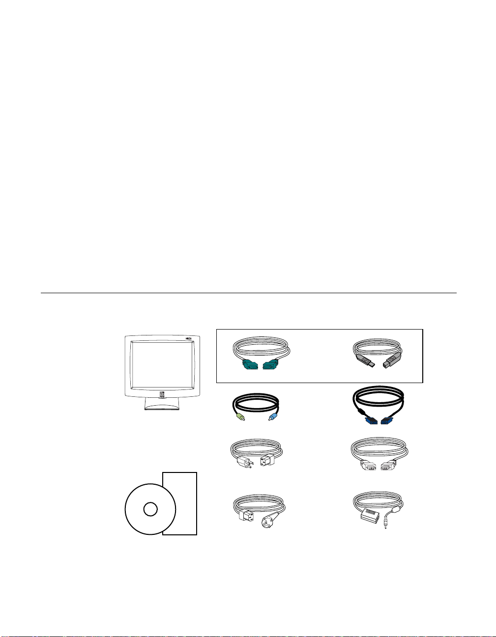
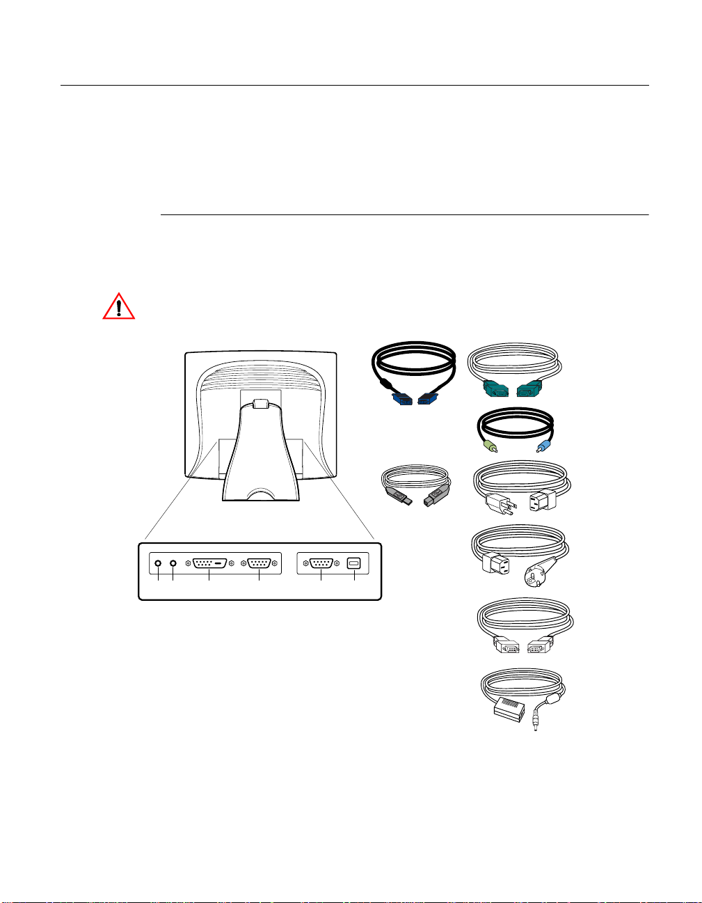
Unpac king Yo ur Touc hmon itor
Check that the following 10 items are present and in good condition:
C HAPTER
2
S
ETUP
Serial touchscreen cable
LCD Display
Quick Install Guide
CD
Software
User Guide-on CD,
Quick Install Guide and software CD
OR
USB Cable
Speaker cable Video cable
Monitor power cable
(US/Canada)
European monitor
power cable
DVI-D video cable
Adapter
2-3
Page 10
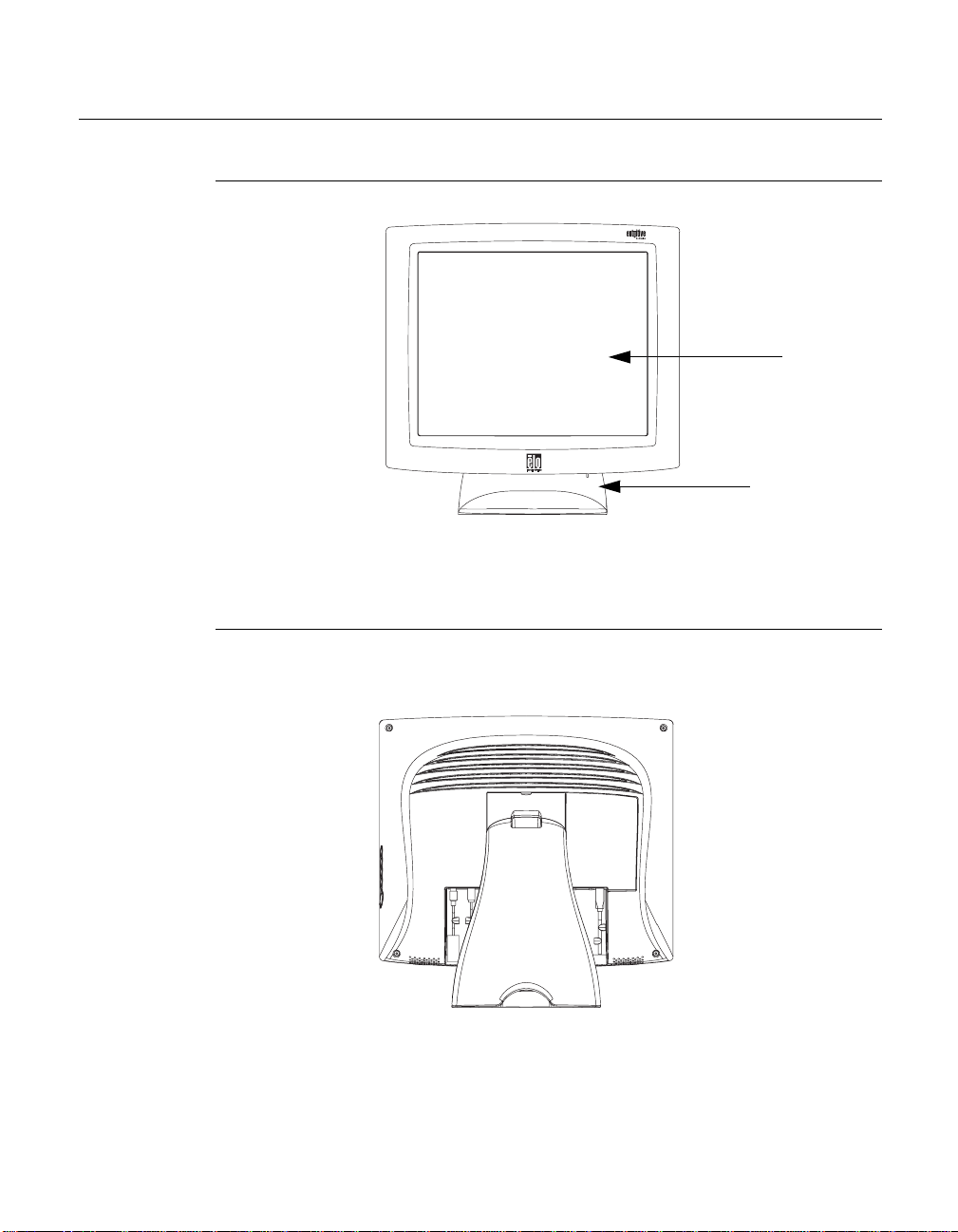
Prod uct Overvie w
Main Unit
Rear View
LCD Display
Stand
2-4 Elo Entuitive Touchmonitor User Guide
Page 11
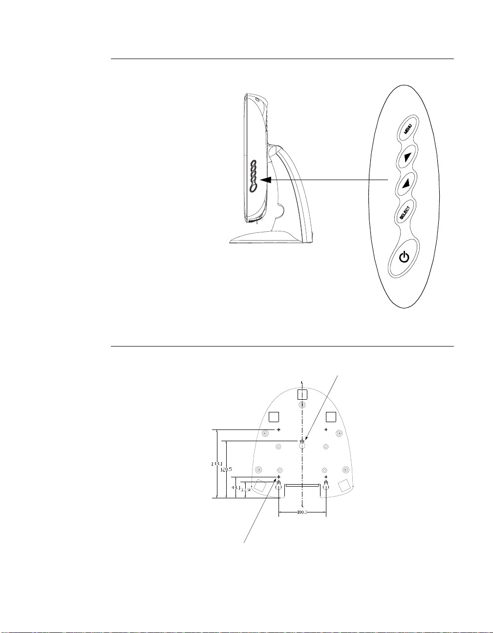
Side View
User Controls
Base Bottom View
4X thread
M5x0.8
Key hole for M5 screw
2-5
Page 12
Touch Interface Connection
Your touchmonitor comes with one of the following touchscreen connector
cables: Serial (RS-232) cable or USB cable. (For Windows 98, 2000, Me and
XP systems only.)
To set up this display, please refer to the following figures and procedures:
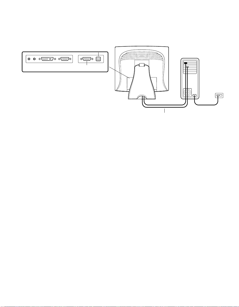
Serial or USB Connection
The following illustrations guide you step by step in connecting your
touchmonitor using a serial or USB cable connection
CAU TION
Before connecting the cables to your touchmonitor and PC, be sure that the computer
and the tou
chmonitor are turned off.
Serial touchscreen
cable
POWER
SPEAKER
PORT
FEMALE DVI-D
VIDEO CONNECTOR
CONNECTIONS ON UNDERSIDE
FEMALE 15-PIN
VIDEO CONNECTOR
FEMALE 9-PIN SERIAL
TOUCHSCREEN CONNECTOR
USB CONNECTOR
Video cable
USB Cable
Speaker cable
Monitor
power cable
(US/Canada)
European monitor
power cable
DVI-D video cable
Adapter
2-6 Elo Entuitive Touchmonitor User Guide
Page 13
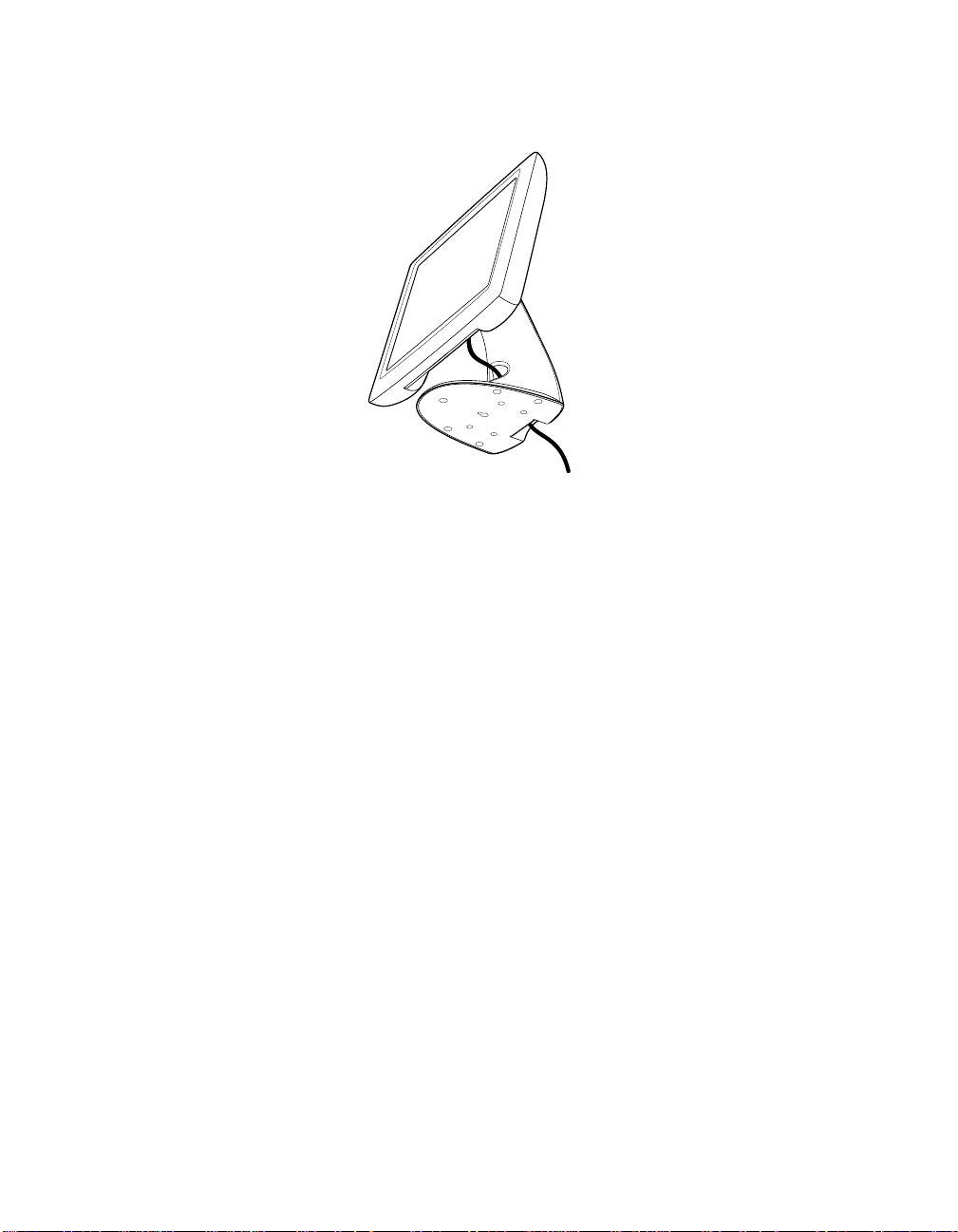
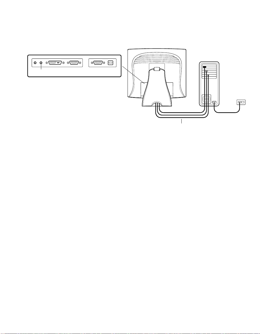
STEP 1-Routing the Cables
• Feed the cables through the cable port holes. Do not remove the rear cover.
2-7
Page 14
STEP 2-Connecting the Video Cable
CONNECTIONS ON UNDERSIDE
VIDEO PORT
FEMALE 15-PIN
VIDEO CONNECTOR
VIDEO CABLE
• Tilt the screen up and back to access the connection ports.
• Connect the 15-pin video cable
to the video port on
your PC.
(the ferrite bead end)
• Connect the other end of the video cable to the video connector on your
touchmonitor by routing the cable through the hole in the stand.
or 24-pin DVI-D cable
• Secure the cable to your touchmonitor and PC by turning the screws on the
connector clockwise.
2-8 Elo Entuitive Touchmonitor User Guide
Page 15
STEP 3-Connecting the Serial or USB Touchscreen Cable
CONNECTORS ON THE UNDERSIDE
TOUCHSCREEN CONNECTOR
USB TOUCHSCREEN
FEMALE 9-PIN SERIAL
CONNECTOR
SERIAL TOUCHSCREEN CABLE
• Connect the female end of the serial (RS-232) cable to the serial port on your
PC, or connect the USB touchscreen cable to the USB touchscreen connector
on the back of your touchmonitor.
• Connect the male end of the cable to the serial touchscreen connector on your
touchmonitor, or connect the other end of the USB touchscreen cable to your
PC.
• Secure the cable to your touchmonitor and PC by turning the screws on the
connector.
2-9
Page 16
SPEAKER
PORT
N
STEP 4-Connecting the Speaker Cable
CONNECTIONS ON UNDERSIDE
OTE
:
If you do not wish to connect the speaker cable, go to step 5.
Connect the light blue end of the speaker cable to the light blue speaker
•
port of the monitor (audio in).
Connect the lime (light green) end of the speaker cable to the lime speaker
•
port on the computer (audio out).
SPEAKER CABLE
2-10 Elo Entuitive Touchmonitor User Guide
Page 17

POWER
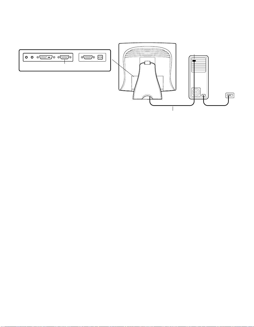
STEP 5-Connecting the P o wer Cable
CONNECTIONS ON UNDERSIDE
N
POWER CABLE
Depending on where you live, you will use either the European or US/Canadian
power cable.
• Connect the female end of the power cable to the
Connect the Brick power cable into the power port on the touchmonitor.
•
Route the cable through the cable management channel.
•
OTE
:
To p
rotect your equipment against risk of damage from electrical surges in the power
line, plug the touchmonitor’s power cord into a surge protector, and then connect the
surge protector to a grounded AC electrical outlet.
Brick power supply.
BRICK POWER SUPPLY
2-11
Page 18

Optimiz ing the LCD D ispla y
To ensure the LCD display works well with your compute r, configure the
display mode of your graphic card to make it less than or equal to 1024 x 768
resolution, and make sure the timing of the display mode is compatible with the
LCD display. Re fer t o Appendix A for more information about resolution.
Compatible video modes for your touchmonitor are listed in Appendix C.
VESA M ount o n Your T o uchm on itor
Your touchmonitor confo rms to the VESA Flat Panel Monitor Physical
Mounting Interface (FPMPMI™) Standard which defines a physical mounting
interface for flat panel monitors, and corresponding standards for flat panel
monitor mounting device s, suc h as wall and table arms. The VESA mounting
interface is located on the back of your touchmonitor and is shipped
pre-connected to the base.
You can also use the existing stand for wall mounting. For mounting dimensions,
go to www.elotouch.com/products/displcds.asp and under Model, click on Elo
Entuitive 1825L/1827L. Click on drawing MS500231.
8X M4x0.7
thr
eaded holes
VESA mounting
interface
N
OTE
:
The abov e drawing displays the VESA mounting interface after the removal of the
mounting co ver and base.
2-12 Elo Entuitive Touchmonitor User Guide
Page 19

N
Accessing the VESA Mounting Interface
If you want to convert your desktop monitor to a wall mount or kiosk monitor,
follow the steps below to acces s the VESA mounting interface.
OTE
:
You will need a screwdriv er for the follo wing steps.
1 Remove the back cover of the stand by pulling f orward on the bottom
cut-out.
2 Carefully lay the monitor face down. At the top of the mounting screw cover
there are two slots. With a screwdriver, pry open the mounting screw cover.
The cover fit is tight so remove it carefully.
3 When you remove the mounting screw cover, you will see four screws.
Remove the screws to mount your monitor. Refer to the drawing o n pag e 18 .
The following companies provide VESA mounting devices compatible with
your touchmonitor :
Ergotron
800-888-8458
651-681-7600
www.ergotron.com
GCX
800-228-2555
707-773-1100
www.gcx.com
Mountin g the Base
You can also mount your touc hmonitor by using the keyholes in the base of the
stand. These keyholes provide easy slide on mounting. You can also bolt your
touchmonitor to a table top or other flat surface. Please ref er to Appendix C for
location and dimension of the mounting holes.
Innovat ive Office Products
800-524-2744
610-253-9554
www.innov-offi ce-prod.com
MRI
800-688-2414
www.mediarecovery.com
2-13
Page 20

Installing the D river Soft ware
Elo TouchSystems provides drive r software that allows your touchmonitor to
work with your computer. Drivers are located on the enclosed CD-ROM for the
following operat ing systems:
• Windows XP
• Windows 2000
• Windows Me
• Windows 98
• Windows 95
• Windows NT 4.0
Additional drivers and driver information for other operating systems are
available on the Elo TouchSystems web site at www.elotouch.com.
Refer to the appropriate following section for driver installation instructions.
2-14 Elo Entuitive Touchmonitor User Guide
Page 21

Installing the Serial T ouch Driver
N
Installing the Serial Touch Driver for
Windows XP,
Windows 2000, Me, 95/98 and NT 4.0
OTE
:
For Win dows 2000 and NT 4.0 you must have administrator access rights to install the
driver.
1 Insert the Elo CD-ROM in your computer’s CD-ROM drive.
2 If the AutoStar t feature for your CD-ROM drive is active , the system
automatically de tects the CD and starts the setup program.
3 Follow the directions on the screen to complete the driver setup for your
version of Windows.
4 If the AutoStart featu re is no t activ e:
5 Click Start > Run.
6 Click the Browse button to locate the EloCd.exe program on the CD-ROM.
7 Click Open, th en OK to run EloCd.exe.
8 Follow the directions on the screen to complete the driver setup for your
version of Windows.
To install Windows 2000 and Windows XP, you must use the "update driver" method;
you will not find a setup.exe file within the download.
2-15
Page 22

Inst a lling the Seri a l Tou c h Driver for MS-DOS and
Windows 3. 1
You must have a DOS mouse driver (MOUSE.COM) installed for your mouse
if you wish to continue using your mouse along with your touchmonitor in
DOS.
To install Windows 3.x and MS-DOS from Windows 95/98, follow the
directions be low:
1 Insert the Elo CD-ROM in your computer’s CD-ROM drive.
2 From DOS, type d:\EloDos_ W31 to change to the correct directory on the
CD-ROM (your CD-ROM drive may be mapped to a different drive letter).
3 Type install and pre ss Enter to start the installation.
4 Align the touchscreen.
You must have already completed Steps 1 and 2 before proceeding. Refer to
Chapter 2 of the Elo DOS and Windows Driver Guide as necessary for
additional ins tallation informati on.
To run the INSTALL program:
1 Type INSTALL at the DOS prompt in the directory containing the driver
install files.
2 INSTALL asks you to select the software to install. Then choose
d:\EloDos_W31 from the displ ayed list.
3 INSTALL also asks you for the paths to use during installation, or you may
use its defaults. INSTALL creates directories as ne cessary, and warns you if
they exist.
If you are updating your softwar e, you may wish to specify the paths conta ining
the earlier versi ons, and overwrite the obsolete files. All executable programs
are upward compatible. For a list of differences from each previous version of
the drivers, be sure to select "Differences from Previous Versions" during the
installat ion process.
INSTALL updates your AUTOEXEC.BAT file with the drivers you select.
INSTALL makes a copy of your original AUTOEXEC.BAT file, cal led
AUTOEXEC.OLD. If you already have Elo driver commands in your
AUTOEXEC.BAT file, they will be commented out.
When INSTALL is finished, it leaves a file called GO.BAT in the subdirector y
you specified. GO loads the touchscreen driver, runs the calibration program
ELOCALIB, and gives you some final instructions.
If you are using Windows 3.1, you will also calibrate the touchscreen within
Windows 3.1 with the Touchscreen Control Panel.
2-16 Elo Entuitive Touchmonitor User Guide
Page 23

N
Installing the USB Touch Driver
Installing the USB Touch Driver for Windows XP,
Windows 2000, Me and 98
1 Insert the Elo CD-ROM in your computer’s CD-ROM drive.
If Windows 98, Windows Me or Windows 2000 starts the Add New
Hardware Wizard:
2 Choose Next. Select “Search for the best driver for your device
(Recommended)” and choose Next.
3 When a list of search locations is displayed, place a checkmark on “Specify a
location” and use Browse to select the \EloUSB directory on the Elo
CD-ROM.
4 Choose Next. Once the Elo TouchSystems USB touchscreen driver has been
detected, choose Next again.
5 You will se e several files being copied. Insert your Windows 98 CD if
prompted. Choose Finish.
If Windows 98, Windows Me or Windows 2000 does not start the Add New
Hardware Wizard:
OTE
:
For Win dows 2000 you must have administrator access rights to install the driver.
1 Insert the Elo CD-ROM in your computer’s CD-ROM drive.
If the AutoStart feature for your CD-ROM drive is active, the system
automatically de tects the CD and starts the setup program.
2 Follow the directions on the screen to complete the driver setup for your
version of Windows.
If the AutoStart feat u re is no t activ e:
1 Click Start > Run.
2 Click the Browse button to locate the EloCd.exe program on the CD-ROM.
3 Click Open, th en OK to run EloCd.exe.
4 Follow the directions on the screen to complete the driver setup for your
version of Windows.
To install Windows 2000 and Windows XP, you must use the "update driver" method;
you will not find a setup.exe file within the download.
2-17
Page 24

2-18 Elo Entuitive Touchmonitor User Guide
Page 25

About T ouchmonitor Adjustments
Your touchmonitor will unlikely require adjustment. Variations in video output
and application may requi re adjustments to your touchmonitor to optimize the
quality of the displa y.
For best perfor ma nc e, your touchmonitor should be operating in native
resolution, that is 1280 x 1024 at 80k-75 Hz. Use the Display control panel in
Windows to choose 1280 x 1024 resolution.
C HAPTER
3
C
HAPTER
3
O
PERATION
Operating in other resolutions will degrade video performance. For further
information, please refer to Appendix A.
All adjustments you make to the controls are automatically memorized. This
feature saves you from having to rese t your choices every time you unplug or
power your touc hmonitor off and on. If there is a power failure your
touchmonitor se ttings will not default to the factory specifications.
Using th e On-Screen Display ( OSD) M enus
All adjustments are made by using the on-screen displa y (OSD) menus. All
menu items can be selected by using the butt ons on the sid e bezel.
N
OTE
:
OSD menu default is enabled.
3-19
Page 26

Side Bezel Buttons
1
2
3
4
5
Control Function
1
2
3
4
5
MEN
U
SELECT
Menu Display/Exits the OSD menus.
Br
ightness/
Plus/Clockwise
MUTE/Minus
Counter-clockwise
Enter Select item
Power Switch Switches on/off the power of your touchmonitor.
Enable/Disable 1
1. Adjust brightness of the OSD.
2. Increase value of the adjustment item.
3. Select item clockwise.
. Enable/Disable MUTE functions.
1
2. Decrease value of the adjustment item.
3. Select item counter-clockwise.
Select- To select the adjustment items from the
OSD menus.
Auto- To activate the “Auto Adjustment” function
to obtain an optimum image.
. Press the Menu and buttons at the same
time and hold for two seconds to enable/disable
the OSD lock functions. OSD menu default is
enabled.
. Press the Menu and buttons at the same
2
time and hold for two seconds to enable/disable
the power lock function.
3-20 Elo Entuitive Touchmonitor User Guide
Page 27

OSD Menu Function
CONTRAST
AUTO CONTRAST
?
?
YUV
Function Symbol Proc e ss
Contrast Controls the picture contrast
Auto Contrast Automatically selects an appropriate contrast setting for the picture.
Brightness Controls the picture brightness.
Left/Right Controls the horizontal position.
Up/Down Controls the vertical position.
Recall defaults Recall factory settings of the image parameters.
Color Temperature In this menu you can select one of the default color temperatures (5500 K,
6
500 K, 7500 K, 9300 K)
values individually using the "USER" option. To define the color values
individually, select the "USER" option. You can switch between the setting
options for R/G/B (red, green and blue foreground) using the OSD direction
button. Select and specify the desired value by using the OSD button.
Press the OSD button or or set color
3-21
Page 28

Information Displays the current graphics mode.
DSUB Analog/ Select the connection for the display: DSUB Analog (15-pin connector) or
DVI Digital
DVI Digital (24-pin connector). In this way you can connect your monitor to
2 computers (by simultaneously using both connectors) and switch between
displays.
Clock Controls the horizontal image size.
Phase Controls the vertical and horizontal fine tuning.
Additional Color Settings
SATURATION Adjusts color intensity.
HUE Adjusts color tint.
YUV
FLESH TONE Adjusts the color so faces appear natural.
OSD Left/Right Adjusts the horizontal position of the OSD menu.
OSD Up/Down Adjusts the vertical position of the OSD menu.
OSD Timeout Determines how long (in seconds) the OSD menu waits before closing
automatically after no action has been performed.
Auto Adjust Automatically selects the optional settings for image parameters (brightness,
contrast, image position, phase etc).
Language Selection of the OSD menu language: English, Fresh, Italian, German,
??
Spanish, Japanese.
Volume Adjusts the volume of the monitor speakers.
Treble Controls the treble of the monitor speakers.
Bass Controls the bass of the monitor speakers.
Balance Controls the balance between the left and right monitor speakers.
3-22 Elo Entuitive Touchmonitor User Guide
Page 29

If you are experien ci ng tro u ble wi th yo ur touchmonitor, refer to the following
table. If the problem persists, please contact your local dealer or our service
center.
Solutions to Common Problems
Problem Suggestion(s)
C HAPTER
4
C
HAPTER
4
T
ROUBLESHOOTING
No image ap pears on screen. Check that all the I/O and power connectors are properly
connecte d as described in Chapter 2.
Make sure the pins of the connectors are not crooked or
broken.
Test power supply by tryi ng different cables, a differe nt
wall outlet or plug another appliance into the outlet.
Make certa in the vi deo cab le is pr ope rly co nne ct ed and t ha t
it is not damaged. Check for bent pins on the cable
connectors.
Ensure that your computer and video card are properly
configur ed. (Consult video card doc um entation.)
“Out of Range” display Check to see if the resolution of your computer is higher
than that of the LCD display.
Reconfigure the resolution of your computer to make it less
than or equal to 1280 x 1024. See Appendix A for more
information on resolution.
OSD/Power buttons don't respond See page 3-20 for OSD enable/disable.
4-23
Page 30

Image has vertical flickering line bars. Use “Phase”tomakeanadjustment.
Check and reco nfigure the display mode of the vertical
refresh ra te of y our gr aph ic car d t o mak e it co mpat ib le wit h
the LCD display.
Image is unstable and flickeri ng Use “CLOCK” to m ake an adjustment.
Image is scrolling Make sure the VGA signal cable (or adapter) is well
connected.
Check and reco nfigure the display mode of the vertical
refresh ra te of y our gr aph ic car d t o mak e it co mpat ib le wit h
the LCD display.
Touch doesn’t work Make sure cable is securely attached at both ends.
4-24 Elo Entuitive Touchmonitor User Guide
Page 31

A PPENDIX
A
C
HAPTER
4
N
ATIVE
The native resolution of a monitor is the resolution level at which the LCD
panel is designed to perfor m best. For the Elo LCD touchmonitor, the native
resolution is 1280 x 1024 for the SXGA-18.1 inch size. In almost all cases,
screen images look best when viewed at their native resolution. You can lower
the resolution setting of a monitor but not increase it.
Input Video 18.1" LCD
640x480 (VGA) Transforms input format to 1280x1024
800x600 (SVGA) Transforms input format to 1280x1024
1024x768 (XGA)
1280x1024 (SXGA) Displays in Native Resolution
Transforms input format to 1280x1024
R
ESOLUTION
The native resolution of an LCD is the actual number of pixels horizontally in
the LCD by the number of pixels vertically in the LCD. LCD resolution is
usually represented by the following symbols:
VGA
SVGA
XGA
SXGA
UXGA
640x480
800x600
1024x768
1280x1024
1600x1200
A-25
Page 32

As an example, a SVGA resolution LCD panel has 800 pixels horizontally by
600 pixels vertically. Input video is also repres ented by the same terms. XGA
input video has a format of 1024 pixels hor izontally by 768 pixels vertically.
When the input pixels containe d in the video input format match the native
resolution of the pa nel, there i s a one to one corre spondenc e of mapping of input
video pixels to LCD pixels. As an example, the pixel in column 45 and row 26
of the input video is in column 45 and row 26 of the LCD. For the case when
the input vide o is a t a lowe r res oluti on than t he nat ive res olution of th e LCD, the
direct corresponde nce between the video pixels and the LCD pixels is lost. The
LCD controller c an compu te the correspon dence between video pi xels a nd LCD
pixels using algorithms contained on its control ler. The accuracy of the
algorithms determines the fidelity of conversion of video pixels to LCD pixels.
Poor fideli ty conversion can r esult in artif acts in the LCD displayed image suc h
as varying width charact ers.
A-26 Elo Entuitive Touchmonitor User Guide
Page 33

A PPENDIX
B
C
HAPTER
4
T
OUCHMONITOR
This manual contains inf ormation that is important for the proper setup and
maintenance of your touc hmonitor. Befor e setti ng u p and poweri ng on your new
touchmonitor, read thr ough this manual, especia lly Chapter 2 (Insta llati on), and
Chapter 3 (Operation).
1 To reduce the risk of electr ic shock, follow all safety notices and never open
the touchmonitor case.
2 Turn off the product before cleaning.
S
AFET Y
3 Your new touc hmonitor is equipped with a 3-wire, grounding power cord.
The power cord plug will onl y fit into a grounde d outlet. Do not attempt to fit
the plug into an outlet that has not been confi gured for this purpose. Do not
use a damaged power cord. Use only the power cord that comes with your
Elo TouchSystems Touchmonitor. Use of an unauthorized power cord may
invalidate your warranty.
4 The slots located on the sides and top of the touchmonitor case are for
ventilatio n. Do not bloc k or insert anything inside the ventilation slots.
5 It is important tha t your touc hmonitor remains dry. Do not pour li quid into or
onto your touchmonitor . If your touchmo nitor becomes wet do not attempt to
repair it yourse lf.
B-27
Page 34

Care an d Handling of Your T o uchm onitor
The following tips will help keep your Elo Entuitive touchmonitor functioning
at the optimal level.
• To avoid risk of electric shock, do not disassemble the brick supply or
display unit cabine t. The unit is not user serviceable. Remember to unplu g
the display unit from the power outlet before cleaning.
• Do not use alcohol (methyl, ethyl or isopropyl) or any strong dissolvent. Do
not use thinner or benzene, abrasive cleaners or compressed air.
• To clean the display unit cabinet, use a cloth lightly dampened with a mild
detergent.
• Avoid getting liquids inside your touchmonitor. If liquid does get inside,
have a qualified servi ce technician check it before you power it on again.
• Do not wipe the screen with a cloth or sponge that could sc ratch the surface.
• To clean the touchscr een, use window or glass cle aner. Put the cleaner on the
rag and wipe the touchscreen. Never apply the cleaner directly on the
touchscreen.
B-28 Elo Entuitive Touchmonitor User Guide
Page 35

Compatib le Video Modes
You r Elo Entuitive touchmonitor is compatible with the following standard
video modes:
A PPENDIX
C
C
HAPTER
4
T
ECH NICALSPECIFICATIONS
Mode
VGA
VGA
VGA 640 x 480 31,470 60
MAC 640 x 480 35,000 66
VESA 640 x 480 37,860 72
VESA 640 x 480 37,500 75
VESA 800 x 600 35,160 56
VESA 800 x 600 37,880 60
VESA 800 x 600 46,880 75
VESA 800 x 600 48,080 72
MAC 832 x 624 49,720 75
SUN 1024 x 768
VESA 1024 x 768 48,360 60
VESA 1024 x 768 56,480 70
VESA 1024 x 768 60,020 75
SXGA 1280 x 1024 64,000 60
SXGA 1280 x 1024 80,000 75
SXGA 1152 x 864 67,500 75
SXGA 1280 x 960 60,000 60
Resolution
720 x 350 31,470 70
720 x 400
H.Frequency(kHz)
31,470
52,450
V
. Frequency(Hz)
65
70
C-29
Page 36

Touc hmo nitor Specificat ions
Table C.1
18.1" LCD Touchmonitor (ET182XL-XXWB-1) Specifications
Display Type
Size
Pixel Format
Touchscreen
Colors
Display
Active matrix, thin film transistor
(TFT), liquid crystal display
18.1-inch diagonal
359.040 x 287.232 mm useful screen
area
1280 x 1024
0.125-inch IntelliTouch and
AccuTouch, anti-glare
Intelli Touch or AccuTouch
16 milli on w ith dithering
IntelliTouch: 210 cd/m² Max. AccuTouch: 188 cd/m² Max.
Brightness
Back-light Lamp
Life
Viewing Ang le
Contrast Ratio
Display R esponse
40,000 hours at 50% brightness
typical
Horizontal
Vertical
400:1 typical
16 ms (tr) /7 ms (tf)
-85~85 or 170 degrees total
-85~85 or 170 degrees total
Time
Environmental
Mechanical
Electrical
Speak ers
Agencies
Operating Temp
Storage Temp
Humidity
Weight
Size
Input Video
Input Power
Power Dissipation
8ohms,2 watt per speaker
Safety & EMC UL, cUL, UL-AR/S, IEC60601-1, MPR II
10°C to 40°C
-20°C to +60°C
80% non-condensing AT
95% IT
28 lbs. maximum approx. weight
for IntelliTouch an d A cc u T ouch
See drawings on page C-34.
VGA/SVGA/XGA/SXGA analogor digital video
Main Adapter:100-240VAC,50/60Hz /LCD:12VDC 4A
Universal
FCC-B, CE, VCCI, C-Tick, ICES-03, CB
C-30 Elo Entuitive Touchmonitor User Guide
Page 37

Table C.2
IntelliTouch Touchmonitor Specification s
Mechanical
Positional Accuracy
Touchpoint Density
Touch Activation
Standard deviation of error is less than 0.080 in. (2.03 mm).
Equate s to les s th an ± 1%.
More than 100,000 touchpoints/in2 (15,500 touchpoints/cm2).
Typically less than 3 ounces (85 grams).
Force
Surface Durability
Expected Life
Performance
Sealin g
Surfac e durability is that of glass, Mohs’ hardness rating of 7.
No know n we ar -o u t mechanis m, as th ere are no la ye rs, coatin g s,
or moving parts. IntelliTouch technology has been operationally
teste d to more th an 50 million touches in one location without
failure, using a stylus similar to a finger.
Unit is sealed to protect against splashed liquids, dirt , and dust.
Optical
Light Transmission
90%
(per ASTM D1003)
Visual Resolution
Gloss (per ASTM
D2457 using a 60degree gloss meter)
All measurem ents made using USAF 1951 Resolution Chart,
under 30X m agnification, with test unit located approximately
1.5 in (38 mm) from surface of resolution chart.
Clear surface: Excellent , with no noticeable degradation.
Antiglare surfa ce: 6:1 minimum.
Antiglare surfa ce: Curved: 60 ± 20 gloss units or 75 ± 15 gloss
units.
C-31
Page 38

Environmental
Chemical Resistance
Electrostatic
Protection (per EN 61
000-4-2, 1995)
The active area of the touchscreen is resistant to all chemicals
that do no t affect glass, such as:
Acetone
Toluene
Methyl et hyl ketone
Isopropyl alcohol
Methyl al cohol
Ethyl ac etate
Ammo ni a-based glass clea n ers
Gasoline
Kerosene
Vinegar
Meets Level 4 (15 kV air/8 kV contact discharges).
C-32 Elo Entuitive Touchmonitor User Guide
Page 39

Table C.3
AccuTouch TouchmonitorSpecifications
Mechanical
Construction
Positional Accuracy
Touchpoin t Dens it y
Touch Activatio n Force
Surface Durability
Expected Life
Performance
Optical
Light Transmis s ion
(per ASTM D1003)
Visual Resolution
Haze (per ASTM D1003)
Gloss (per ASTM D2457)
Top: Pol ye s te r w ith outside har d -s ur face coatin g with clear or
antiglare finish.
Inside: Transparent conductive coating.
Bottom: G lass substrate with uniform resistive coating. Top and
bottom layers separated by Elo-patented separator dots.
Standard deviation of error is less tha n 0.080 in. (2.03 mm). This
equates to less than ±1%.
More than 100,000 touchpoints/ in² (15,500 touchpoints/cm²).
Typically less th an 4 ounces (113 grams).
Meets Taber Abrasion Test (ASTM D1044), CS-10F wheel, 500 g.
Meets pencil hardness 3H.
AccuTouch technology has been operationally tested to greater than
35 mill ion touches in one location without failure, using a stylus
similar to a finger.
Typically 75% at 550-nm wavelength (visible light spectrum).
All measurements made using USAF 1951 Resolution Chart, under
30 X magnification, with test unit located approximately 1.5 in. (38
mm) from surface of resolution chart.
Antiglare surf ace: 6:1 minimum.
Antiglare surface: Less than 15%.
Antiglare surface: 90 ± 20 gloss units tested on a hard-coated front
surface.
C-33
Page 40

18.1"LCD T ouc hm onitor (ET182XL-XXW B -X) Dimensions
444mm [17.47"]
359mm [14.14"]
287mm [11.31"]
385mm [15.17"]
437mm [17.20"]
220mm [8.65"]
C-34 Elo Entuitive Touchmonitor User Guide
280mm [11.03"]
Page 41

See Detail A
77mm [3.03"]
10mm [0.39"]
244mm [9.62"]
Detail A
C-35
Page 42

C-36 Elo Entuitive Touchmonitor User Guide
Page 43

C
HAPTER
4
R
EGULATORY INFORMATION
I. Electrical Safety Information:
A) Compliance is required with respect to the voltage, frequency, and current
requirements indicated on the manufacturer’s label. Connection to a different
power source than those specified herein will likely result in improper operation,
damage to the equipment or pose a fi re hazard if the limitat ions are not followed.
B) There are no operator serviceable parts inside this equipment. There are hazardous voltages generated by this equipment which constitute a safety hazard. Service
should be pr ovided only by a qualified service technician.
C) This equipment is provided with a detachable power cord which has an integral
safety ground wire intended for connection to a grounded safety outlet.
1) Do not substi tute the co rd with ot her than th e provided approved typ e.
Under no circumstances use an adapter plug to connect to a 2-wire outlet as
this will defeat the continuity of the gr ounding wire.
2) The equipment requires the use of the ground wire as a part of the safety
certification, modification or misuse can provide a shock hazard that can
result in serious injury or death.
3) Contact a qualified electrician or the m anufacturer if there are questions
about the installation prio r to connecting the equipment t o mains pow er.
II. Emissions and Immunity Information
A) Notice to Users in the United States: This equipment has been tested and found
to comply with the limits for a Class B digital device, pursuant to Part 15 of FCC
Rules. These limits are designed to provide reasonable protection against harmful
interference in a residential installation. This equipment generates, uses, and can
radiate radio frequency energy, and if not installed and used in accordance with the
instructions, may cause harmful interference to radio communications.
B) Notice to Users in Canada: This equipment compl ies with the Class B limits for
radio noise emissions from digital apparatus as established by the Radio Interference Regulations of Industrie Canada.
C) Notic e to U sers in the Europea n U ni o n: Use only th e provided pow e r co rd s and
interconnecting cabling provided with the equipment. Substitution of provided
cords and cabling may compromise electrical safety or CE Mark Certification for
emission s or immunity as required by the following standards:
37
Page 44

This Infor m ation Technology Equipment (ITE) is required to have a CE Mark
on the manufacturer’s label which means that the equipment has been tested
to the foll owing Directives and Standards:
This equipment has been tested to the requirements for the CE Mark as
required by EMC Directive 89/336/EEC indicated in European Standard EN
55 022 Class B and the Low Voltage Directive 73/23/EEC as indicated in
European Sta ndard EN 60 950.
D) General Information to all Users: This equipment generates, uses and can radiate radio frequency energy. If not installed and used according to this manual the
equipment may cause interference with radio and television communications.
There is, however, no guarantee that interference will not occur in any particular
instal lation due to site-specific factors.
1) In order to meet emission and immunity requirements, the user must
observe the following:
a) Use only the provided I/O cables to connect this digital device with
any computer.
b) To ensure compliance, use only t h e provided manufacturer’s approved
line cord.
c) The user is cautioned that changes or modifications to the equipment
not expressly approved by the party responsible for compliance could
void the user’s authority to operate the equipment.
2) I f this equi pment appea rs to caus e interfere nce with r adio or tel evision
reception, or any other device:
a) Verify as an emission source by turni ng the equipment off and on.
b) If you de te rmine tha t th is equipme n t is cau s ing the inter ference , tr y to
correct the interference by using one or more of the following measures:
i) Move the digital devi ce away from the affected rec eiver.
ii) Reposition (turn) the digital device with respect to the affected
receiver.
iii) Reorient the affected receiver’s antenna.
iv) Plug the digital device into a different AC outlet so the digital
device and the receiver are on different branch circuits.
v) Disconnect and remove any I/O cables that the digital device
does not use. (Unterminated I/O cables are a potential source of
high RF emission levels.)
vi) Plug the digital device into only a grounded outlet receptacle.
Do not use AC adapter plugs. (Removing or cutting the line cord
ground may increase RF emission levels and may also present a
lethal shock hazard to the user.)
If you need additional help, consult your dealer, manufacturer, or an experienced radi o or television technician.
38 Elo Entuitive Touchmonitor User Guide
Page 45

E230760
WITH RESPECT TO ELECTRIC SHOCK,
FIRE AND MECHANICAL HAZARDS ONLY
IN ACCORDANCE WITH UL2601-1
CAN/CSA C22.2 No. 601.1
IEC
60601-1
Tested To Comply
With FCC Standards
N10051
"This Class B digital apparatus meets all requirements of the Canadian Interference-Causing Equipment
Regulations.
Cet appareil numérique de la classe B respecte toutes les exigences du Règlement sur le matériel brouilleur
du Canada."
39
Page 46

40 Elo Entuitive Touchmonitor User Guide
Page 47

C
HAPTER
4
W
ARRANTY
Except as otherwise stated herein or in an order acknowledgment delive red to
Buyer, Seller warrants to Buyer that the Product shall be free of defects in
materials and workmanship. The warranty for the touchmonitor s and
components of th e product are: 3 years monitor, 10 years IntelliTouch screen, 5
years Accu- Touch screen, 5 years Controller.
Seller makes no warranty regarding the model life of components. Seller’s
suppliers may at any time and from time to time make change s in the
components deliver ed as Products or components.
Buyer shall notify Seller in writing promptly (and in no case later than thirty
(30) days after discov ery) of the failure of any Product to conform to the
warranty set forth abo ve ; shal l des crib e i n com me rci ally reasonable detail in
such notice the symptoms assoc iated with such failure; and shall provide to
Seller the opportun ity to inspect such Products as installed, if possible. The
notice must be received by Selle r during the Warranty Per iod for such p roduct,
unless otherwise directed in writing by the Seller. Within thirty (30) days after
submitting such noti ce, Bu yer shall package the allegedly defective Product in
its original ship ping carton(s) or a functional equivalent and shall ship to Seller
at Buyer’s expense and risk.
Within a reasonable time after receipt of the allegedly defect ive Product and
verification by Seller that the Product fails to meet the warranty set forth above ,
Seller shall corr ect such failure by, at Seller’s opt ions, either (i) modifying or
repairing t he Product or (ii) r eplacing the Product. Such modification , r epair, or
replacement and the return shipment of the Product with minimum ins urance to
Buyer shall be at Se ller’s expense. Buye r shall be ar the r isk of loss or damage in
transit, and may insure the Product. Buyer shall reimburse Selle r for
transportat ion cost incurred for Product returned but not found by Seller to be
defective. Modifi cation or repair , of Products may, at Seller’ s option , take place
either at Seller ’s facilities or at Buyer’s premises. If Seller is unable to modify,
repair, or replace a Product to conform to the warranty set forth above, the n
Seller shall, at Seller’s option, either refund to Buyer or credit to Buyer’s
account the purchase price of the Product less depreciation c alculated on a
straight-line basis over Seller’s sta ted Warranty Period.
41
Page 48

THESE REMEDIES SHALL BE THE BUYER’S EXCLUSIVE REMEDIES
FOR BREACH OF WARRANTY. EXCEPT FOR THE EXPRESS
WARRANTY SET FORTH ABOVE, SELLER GRANTS NO OTHER
WARRANTIES, EXPRESS OR IM PLIED BY STATUTE OR OTHERWISE,
REGARDING THE PRODUCTS, THEIR FITNESS FOR ANY PURPOSE,
THEIR QUALITY, THEIR MERCHANTABILITY, THEIR
NONINFRINGEMENT, OR OTHERWISE. NO EMPLOYEE OF SELLER
OR ANY OTHER PARTY IS AUTHORIZED TO MAKE ANY WARRANTY
FOR THE GOODS OTHER THAN THE WARRANTY SET FORTH
HEREIN. SELLER’S LIABILITY UNDER THE WARRANTY SHALL BE
LIMITED TO A REFUND OF THE PURCHASE PRICE OF THE PRODUCT.
IN NO EVENT SHALL SELLER BE LIABLE FOR THE COST OF
PROCUREMENT OR INSTALLATION OF SUBSTITUTE GOODS BY
BUYER OR FOR ANY SPECIAL, CONSEQUENTIAL, INDIRECT, OR
INCIDENTAL DAMAGES.
Buyer assumes the risk and agrees to inde mnify Seller against and hold Seller
harmless from all liability relating to (i) assessing the suitability f or Buyer’s
intended use of the Product s and of any system design or drawing and (ii)
determining the complia nce of Buyer’s use of the Products with applicable
laws, regulations, codes, and standards. Buy er reta ins and accepts full
responsibil ity for all warranty and other claims relating to or arising from
Buyer’s products, which include or incorporate Products or components
manufactured or supplied by Seller. Buyer is solely responsible for any and all
representations and warrantie s regarding the Products made or authorized by
Buyer. Buyer will indemnify Seller and hold Seller harmless from any liability,
claims, los s, cos t, or expe nses (inc lu ding rea sonable a tto rney’s fees) attribu tab le
to Buyer’s products or representations or warranties concerning same.
42 Elo Entuitive Touchmonitor User Guide
Page 49

INDEX
Numerics
18.1" LCD Touchmonitor (ET182XL-XXWB-X) Dimensions, 34
18.1" LCD Touchmonitor (ET182XL-XXWB-X) Specifications, 30
A
About the Product, 1
About Touchmonitor Adjustments, 19
Accessing the VESA Mounting Interface, 13
AccuTouch Touchmonitor Specifications, 33
Additional Color setting, 22
Agencies, 30
Analog Contrast, 21
Auto Adjust, 22
Auto Contrast, 21
B
Back-light Lamp Life, 30
Balance, 22
Base Bottom View, 5
Bass, 22
B
rightness, 20,21
C
Care and Handling of Your Touchmonitor, 28
Chemical Resistance, IntelliTouch, 32
Cleaning Y our T ouchmonitor , 28
Clock, 22
Colors T emperature , 21
Compatible Video Modes, 29
Connecting the Power Cable, 11
Connecting the Remote OSD Cable, 10
Connecting the Serial or USB Touchscreen Cable, 9
Connecting the Speaker Cable, 10
Connecting the Video Cable, 8
Construction, AccuTouch, 33
Contrast, 21
Contrast Ratio, 30
D
Display Brightness, 30
Display Response Time, 30
Display Type, 30
DSUB Analog/DVI Digital, 22
F
Flesh T one , 22
G
Gloss, AccuTouch, 33
Gloss, IntelliTouch, 31
H
Haze, AccuTouch, 33
Hue, 22
I
Image Information, 22
Image problem, 23
Image, scrolling, 24
Image, unstable, 24
Image, vertical flickering, 24
Installation and Setup, 3
Installing the Driver Software, 14
Installing the Serial Touch Driver, 15
Installing the Serial Touch Driver for MS-DOS and
Windows 3.1, 16
Installing the Serial Touch Driver for Windows XP, 2000,
Me, 95/98 and NT 4.0, 15
Installing the USB Touch Driver, 17
Installing the USB Touch Driver for Windows XP, 2000, Me
and 98, 17
IntelliTouch Touchmonitor Specifications, 31
Introduction, 1
L
Light Transmission, AccuTouch, 33
Light Transmission, IntelliTouch, 31
M
Main Unit, 4
Mechanical, 30
Mechanical, AccuTouch, 33
Mechanical, IntelliTouch, 31
Menu, 20
Mute/Minus Counter-clockwise, 20
Mounting the Base, 13
E
Electrical, 30
Electrical Safety Information, 31
Electrostatic Protection, IntelliTouch, 32
Emissions and Immunity Information, 31
Enable/Disable, 20
Enter Select item, 20
Environmental, 30, 32
Expected Life Performance, AccuTouch, 33
Expected Life Performance, IntelliTouch, 31
N
Native Resolution, 25
Index-43
Page 50

O
Operation, 19
Optical, AccuTouch, 33
Optical, IntelliTouch, 31
Optimizing the LCD Display, 12
OSD Left/Right, 22
OSD Menu Function, 21
OSD Timeout, 22
OSD Up/Down, 22
OSD Power, Respond, 23
Out of Range display, 23
P
Phase, 22
Pixel Format, 30
Positional Accuracy, AccuTouch, 33
Positional Accuracy, IntelliTouch, 31
Power Switch, 26
Precautions, 1
Product Overview, 4
R
Rear View, 4
Recall Defaults, 21
Regulatory Information, 37
Routing the cables, 7
T
Technical Specifications, 29
Touch Activation Force, AccuTouch, 33
Touch Activation Force, IntelliTouch, 31
Touch Interface Connection, 6
Touch not working, 24
Touchmonitor Safety, 27
Touchmonitor Specifications, 30
Touchpoint Density, AccuTouch, 33
Touchpoint Density, IntelliTouch, 31
Treble, 22
Troubleshooting, 23
U
Unpacking Your Touchmonitor, 3
Using the On-Screen Display (OSD) Menus, 19
Up/Down, 21
UXGA, 25
V
VESA Mount on Your Touchmonitor, 12
VGA, 25
Viewing Angle, 30
Visual Resolution, AccuTouch, 33
Visual Resolution, IntelliTouch, 31
Volume, 22
S
Saturation, 22
Sealing, IntelliTouch, 31
Serial or USB Connection, 6
Side Bezel Buttons, 20
Side View, 5
Solutions to Common Problems, 23
Speakers, 30
Surface Durability, AccuTouch, 33
Surface Durability, IntelliTouch, 31
SVGA, 25
SXGA, 25
W
Warranty, 41
X
XGA, 25
Index-44
Page 51

Check out Elo's W
eb site!
www.elotouch.com
Get the latest...
• Product information
• Specifications
• News on upcoming events
• Press
• Software
Getting in T
To find out more about Elo’s extensive range of touch solutions, visit our Web site at www.elotouch.com
or simply call the office nearest you:
USA
Elo TouchSystems, Inc.
6500 Kaiser Drive
Fremont, CA 94555-3613
(800) ELO-TOUCH (800-356-8682)
Tel 510-739-5016
Fax 510-790-0627
eloinfo@elotouch.com
releases
drivers
ouch with Elo
Germany
Elo TouchSystems GmbH & Co. KG
Haidgraben 6
D-85521 Ottobrunn
Germany
Tel +49(89)60822-0
Fax +49(89)60822-150
elosales@elotouch.com
Belgium
Elo TouchSystems
Diestsesteenweg 692
B-3010 Kessel-Lo
Belgium
Tel +32(16)35-2100
Fax +32(16)35-2101
elosales@elotouch.com
Japan
Touch Panel Systems K.K
Sun Homada Bldg. 2F
1-19-20 Shin-Yokohama,
Kanagawa 222-0033
Japan
Tel +81(45)478-2161
Fax +81(45)478-2180
www.tps.co.jp
2002 Elo TouchSystems, Inc.Pinted in USA
 Loading...