

Page 1
ELO Entuitive Touchmonitor
User Guide
For 17" LCD Desktop Touchmonitors
1725L/1727L Series
Revision A
Page 2
Elo Entuitive Touchmonitor
User Guide
17" LCD Desktop Touchmonitor
1725L/1727L Series
Revision A
P/N 008555
Elo TouchSystems, Inc.
1-800-ELOTOUCH
www.elotouch.com
Page 3

Page 4

Copyright © 2002 Elo TouchSystem s Inc. All Rights Reserved.
No part of this publication may be reproduced, transmitted, transcribed, stored in a ret rieval system,
or tr ans lated into any language or computer language, in any form or by any means, including, b ut not
limited to, electronic, magnetic, optical, chemical, manual, or otherwise without prior written
permission of El o TouchSyste m s .
Disclaimer
The info rmation in thi s document is subject to change without notice. Elo TouchSystems makes no
representations or warranties with respect to the contents hereof, and specifically disclaims any
implied warranti es of merchanta bility o r fitness for a particula r purpose. El o TouchSystems reserves
the right to revise this publication and to make changes from time to time in the content hereof
with ou t ob ligation of El o TouchSystem s t o no t i f y an y perso n of s uc h r ev i s ions or chang es.
Trademark Acknowledgments
IntelliTouch, iTouch, SecureTouch, AccuTouch, Entuitive, and MonitorMouse are trademarks of Elo
TouchSystems Inc.
Other product names mentioned herein may be trademarks or registered trademarks of their
respective companies. Elo TouchSystems claims no int erest in trademar ks other than its own.
iii
Page 5

iv
Page 6

Table of Contents
Chapter 1
Introduction 1
Precautions . . . . . . . . . . . . . . . . . . . . 1
About the Product . . . . . . . . . . . . . . . . . 1
Chapter 2
Installation and Setup 3
Unpacking Your Touchmonitor. . . . . . . . . . . 3
Product Overview . . . . . . . . . . . . . . . . . 4
Main Unit . . . . . . . . . . . . . . . . . . . . 4
Rear View . . . . . . . . . . . . . . . . . . . 4
Side View. . . . . . . . . . . . . . . . . . . . 5
Base Bottom View . . . . . . . . . . . . . . . 5
Touch Interface Connecti on . . . . . . . . . . . . 6
Serial or USB Connection . . . . . . . . . . . 6
STEP 1-Routing the Cables . . . . . . . . . 7
STEP 2-Connect ing the Video Cable. . . . 8
STEP 3-Connecting the Serial or USB
Touchscreen Cable . . . . . . . . . . . . . 9
STEP 4-Connecting the Speaker Cable . 10
STEP 5-Connecting the Power Cable. . . 11
Optimizing the LCD Display . . . . . . . . . . . 12
VESA Mount on Your Touchmonitor. . . . . . . 12
Accessing the VESA Mounting Interface . . . 13
Mounting the Base . . . . . . . . . . . . . . . 13
Installing the Driver Software . . . . . . . . . . 14
Installing the Se r ia l Touch D r ive r. . . . . . . 15
Install ing the Serial Touch Driver for Windo ws
XP, 2000, Me, 95/98 and NT 4.0 . . . . . 15
Install ing t he Serial Touch Driver for MS-DOS
and Windows 3.1 . . . . . . . . . . . . . 16
Installing the USB Touch Driver . . . . . . . 17
Installing the USB Touch Driver for Windows
XP, 2000, Me and 98 . . . . . . . . . . . 17
Chapter 3
Operation 19
About Touchmonitor Adjustments. . . . . . . . 19
Using the On-Screen Display (OSD) Menus . . 19
Side Bezel Buttons . . . . . . . . . . . . . . . 20
OSD Menu Function . . . . . . . . . . . . . . 21
Auto Adjustment . . . . . . . . . . . . . . . . 22
Chapter 4
Troubleshooting 23
Solutions to Common Problems . . . . . . . . 23
Appendix A
Native Resol utio n 25
Appendix B
Touchmonitor Safety 27
Care and Handling of Your Touchmonitor. . . . 28
Appendix C
Technical Specificatio ns 29
Compatible Video Modes . . . . . . . . . . . . 29
Touchmonitor Specif ications . . . . . . . . . . 30
17" LCD Touchmonitor (ET172XL-XXWB-X)
Dimensions . . . . . . . . . . . . . . . . . . 34
Regulatory Information 37
Warranty 41
Index 43
v
Page 7

vi
Page 8

C HAPTER
1
C
HAPTER
1
I
NTRODUCTION
Congratulations on your purchase of an Elo TouchSyst ems Entuitive
touchmonitor . Your new touchmonitor combines the reliable performance of
Elo’s touch technology with the latest advances in LCD display design. This
combination of features creates a natural flow of information between a user
and your touchmonitor .
Precautions
Follow all warnings, precautions and maintenance as recommended in this
user’s manual to maximi ze the life of your unit. See Appendix B for more
information on touc hmonitor safety.
Abou t the Pr od uct
Your LCD Desktop Touchmonitor is a 17.0” SXGA TFT color display with the
following featur es:
• Direct analog RGB or Digital RGB input
• 17.0” diagonal screen size
• 16.7 million displayable colors
• 1280 x 1024 resolution
• SXGA/XGA/SVGA/VGA/VESA/Mac compatible
• 30kHz~80kHz horiz o ntal scan
• 56~75Hz refresh rate
1-1
Page 9

• Auto adjustment capability
• High quality full sc reen re-scaling
• Multilingua l OSD menus in six languages: English, French, German,
Spanish, Italian and Japanese
• Serial or US B tou c h interface (USB requ ir es Windows 98, 2000, Me and
XP.)
• Built in speakers with volume, treble, bass and balance control through OSD
• Patented touch technology of Elo TouchSystems
• VESA DDC 1/2B data communication
• VESA DPMS power saving
• Stand with minimum 95° angle of tilt.
• Cable management device
• VESA flat panel monitor physical mou nting interface (Both of 75 & 100mm)
• OSD and Power button lockouts
• Wall mountable with existing stand
• M5 threaded holes on bottom of stand for securing to desk or other surface,
i.e. table top
• Cable stain reliefs for all cables
For full Product Specifications refer to Appendix C.
1-2 Elo Entuitive Touchmonitor User Guide
Page 10
C
HAPTER
2
I
NSTALLATION AND
This chapter disc usses how to install your LCD touchmonito r and how to install
Elo TouchSyste ms driver software.
Unpac king Your Touc hmon itor
C HAPTER
2
S
ETUP
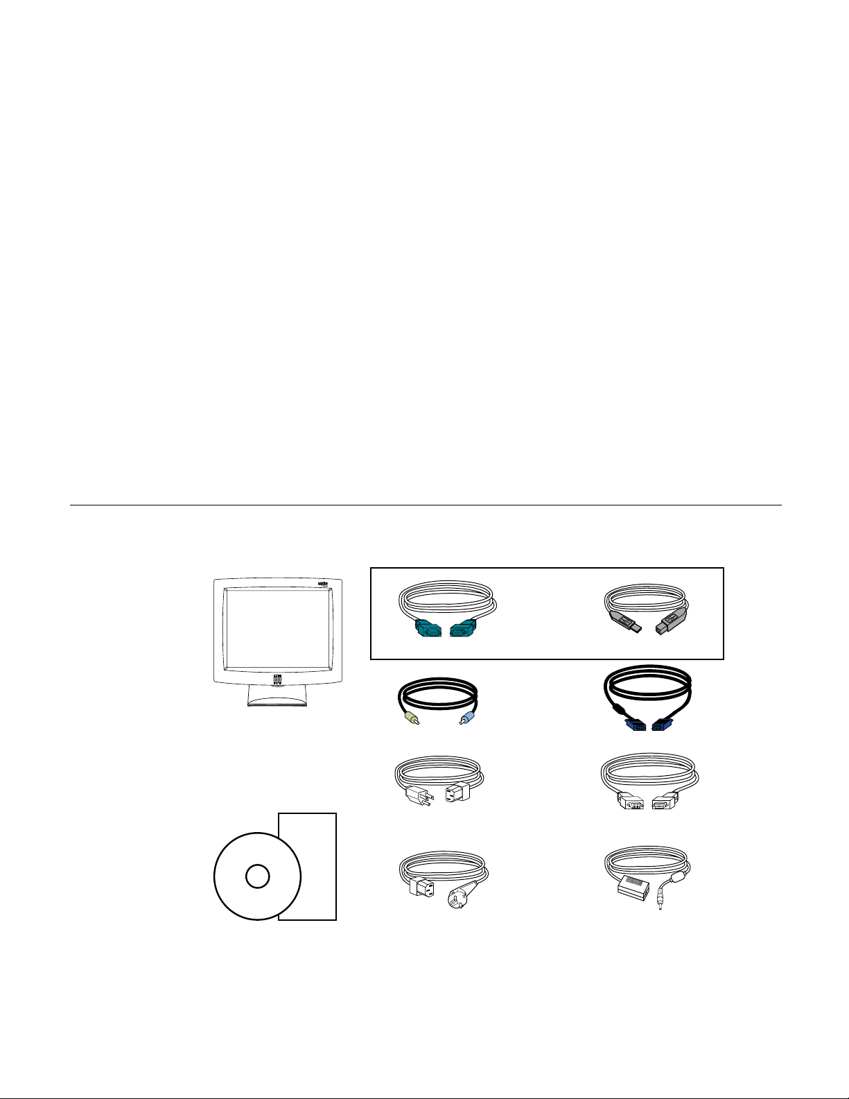
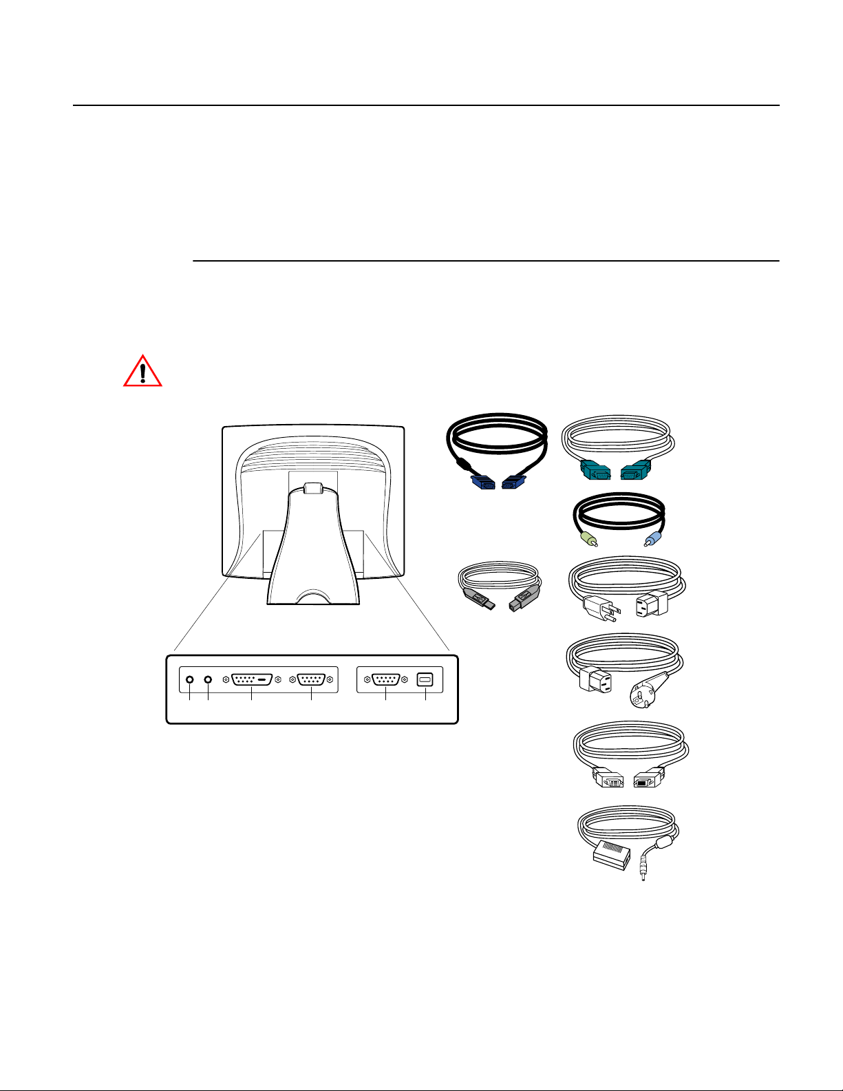
Check that the following 10 ite ms are present and in good condition:
OR
Serial touchscreen cable
LCD Display
Quick Install Guide
CD
Software
User Guide-on CD,
Quick Install Guide and software CD
Speaker cable Video cable
Monitor power cable
(US/Canada)
European monitor
power cable
USB Cable
DVI-D video cable
Adapter
2-3
Page 11
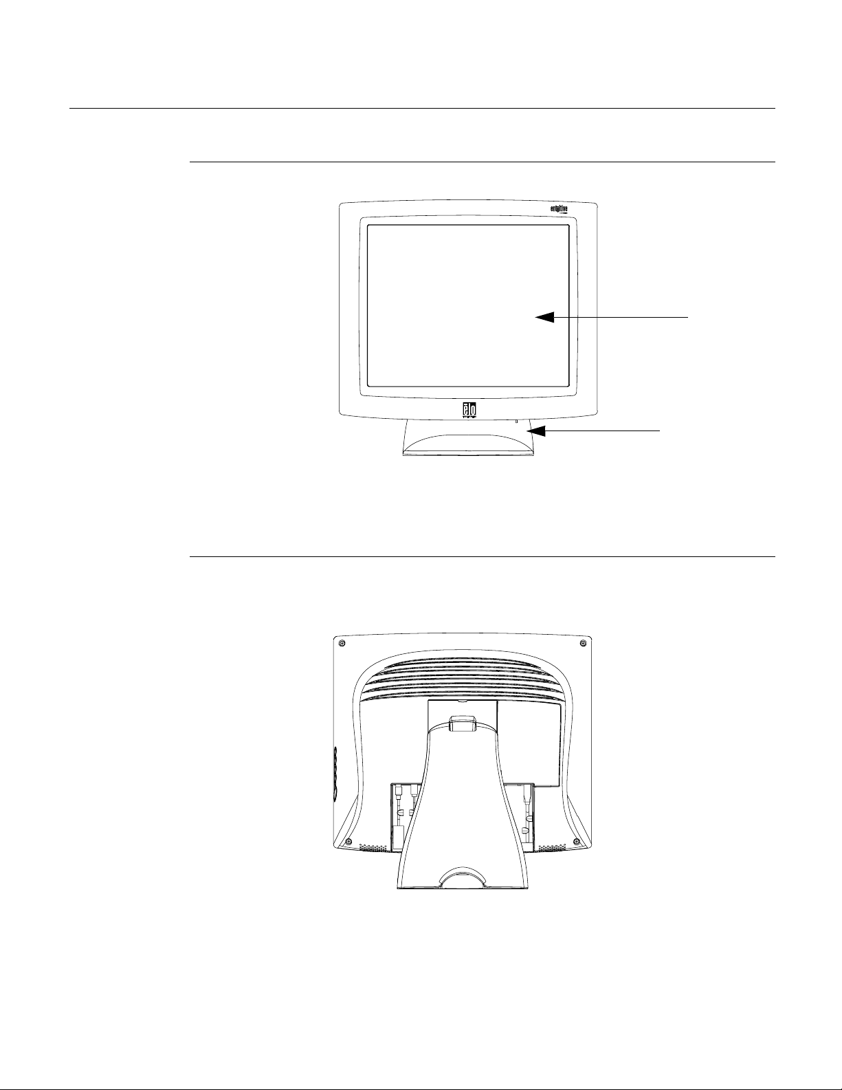
Pr oduct O vervie w
Main Unit
LCD Display
Stand
Rear View
2-4 Elo Entuitive Touchmonitor User Guide
Page 12
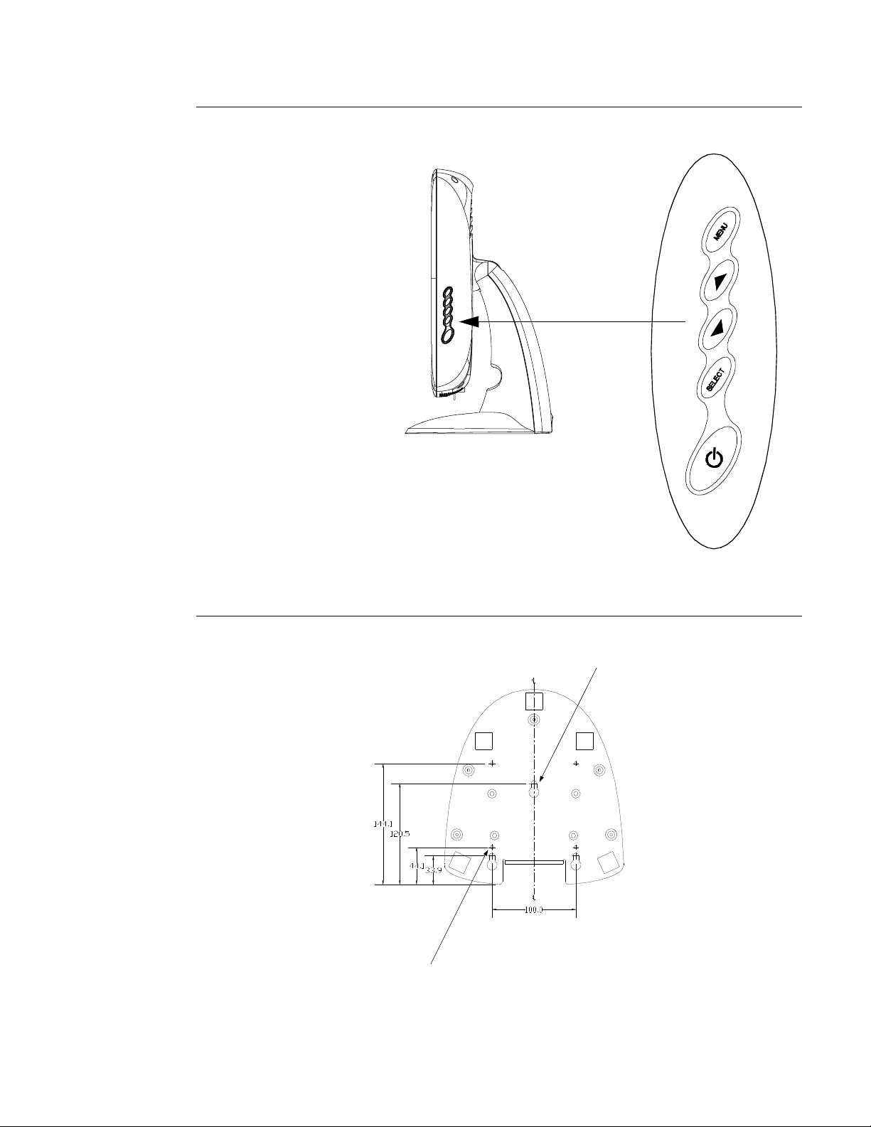
Side View
User Controls
Base Bottom View
4X thread
M5x0.8
Key hole for M5 screw
2-5
Page 13
Touch Interface Connection
Yo ur touchmonitor comes with one of the following touchscreen connector
cables: Serial (RS-232) cable or USB cable. (For Windows 98, 2000, Me and
XP systems only.)
To set up this display, please refer to the following figures and procedures:
Serial or USB Connection
The following illustrations guide you step by step in connecting your
touchmonitor using a serial or USB cable connection
CAUTION
Before connecting the cables to your touchmonitor and PC, be sure that the computer
and the touchmonitor are turned off.
Serial touchscreen
cable
POWER
SPEAKER
PORT
FEMALE DVI-D
VIDEO CONNECTOR
CONNECTIONS ON UNDERSIDE
FEMALE 15-PIN
VIDEO CONNECTOR
TOUCHSCREEN CONNECTOR
FEMALE 9-PIN SERIAL
Video cable
USB Cable
USB CONNECTOR
Speaker cable
Monitor
power cable
(US/Canada)
European monitor
power cable
2-6 Elo Entuitive Touchmonitor User Guide
DVI-D video cable
Adapter
Page 14
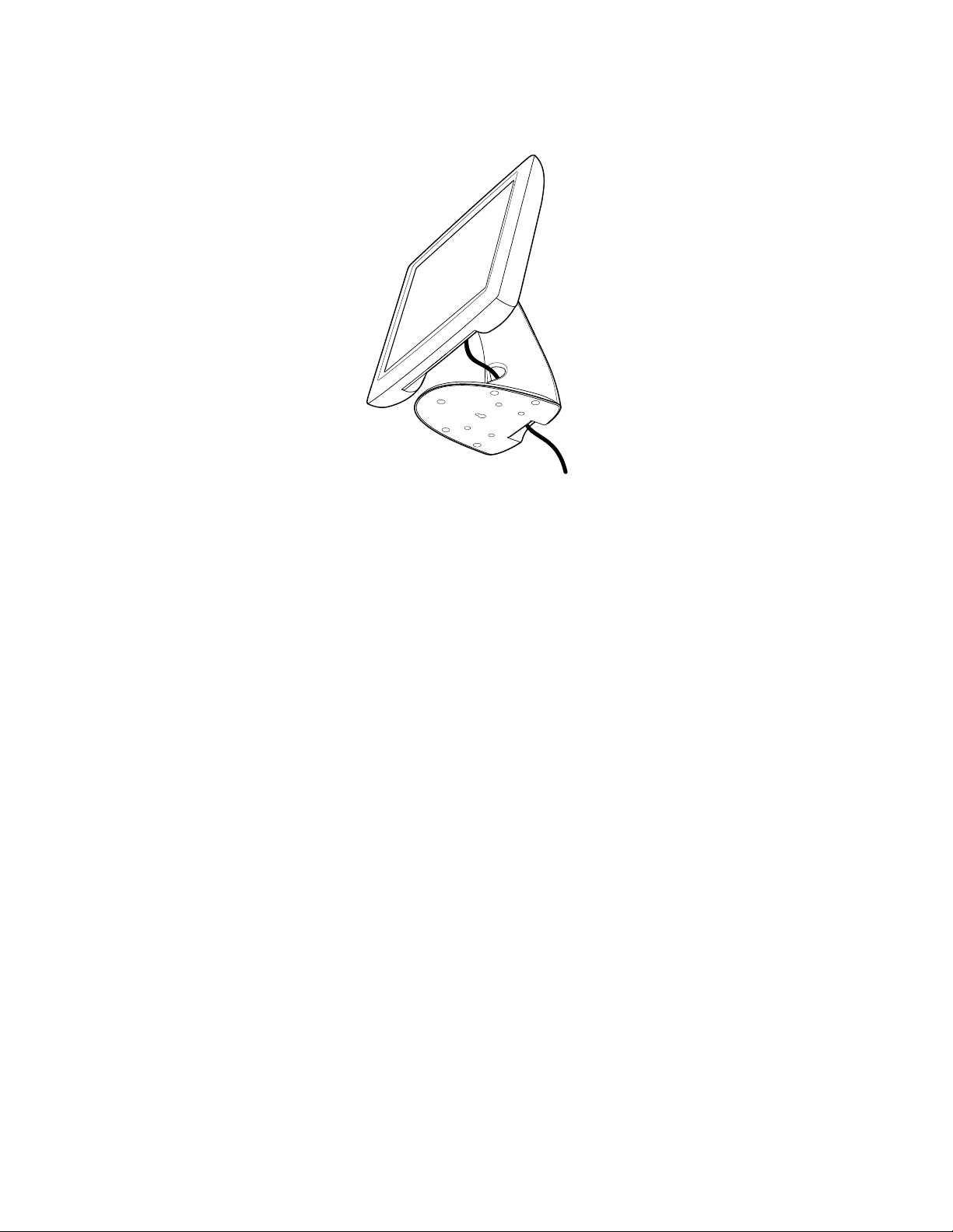
STEP 1-Routing the Cables
• Feed the cables through the cable port holes. Do not remove the rear cover.
2-7
Page 15

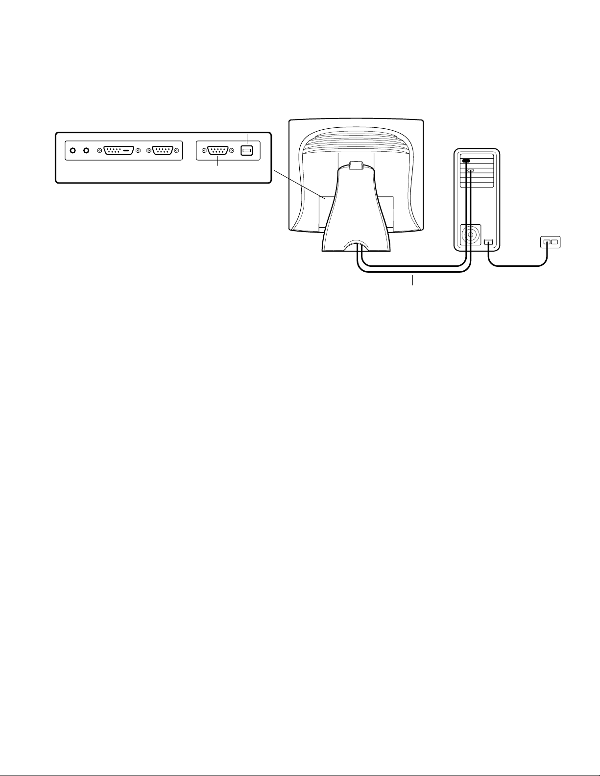
STEP 2-Connecting the Video Cable
CONNECTIONS ON UNDERSIDE
FEMALE 15-PIN
VIDEO CONNECTOR
VIDEO CABLE
• Tilt the screen up and back to access the connection ports.
VIDEO PORT
• Connect the 15-pin video cable
to the video port on
your PC.
(the ferrite bead end)
or 24-pin DVI-D cable
• Connect the other end of the video cable to the video connector on your
touchmonitor by routing the cable through the hole in the stand.
• Secure the cable to your touchmonitor and PC by turning the screws on the
connector clockwise.
2-8 Elo Entuitive Touchmonitor User Guide
Page 16
STEP 3-Connecting the Serial or USB Touchscreen Cable
CONNECTORS ON THE UNDERSIDE
TOUCHSCREEN CONNECTOR
FEMALE 9-PIN SERIAL
USB TOUCHSCREEN
CONNECTOR
SERIAL TOUCHSCREEN CABLE
• Connect the female end of the serial (RS-232) cable to the serial port on your
PC, or connect the USB touchscreen cable to the USB touchscreen connector
on the back of your touchmonitor.
• Connect the male end of the cable to the serial touchscreen connector on your
touchmonitor, or connect the other end of the USB touchscreen cable to your
PC.
• Secure the cable to your touchmonitor and PC by turning the screws on the
connector.
2-9
Page 17

SPEAKER
PORT
STEP 4-Connecting the Speaker Cable
CONNECTIONS ON UNDERSIDE
SPEAKER CABLE
N
OTE
:
If you do not wish to connect the speaker cable, go to step 5.
Connect the light blue end of the speaker cable to the light blue speaker
•
port of the monitor (audio in).
Connect the lime (light green) end of the speaker cable to the lime speaker
•
port on the computer (audio out).
2-10 Elo Entuitive Touchmonitor User Guide
Page 18

POWER
STEP 5-Connecting the Power Cable
CONNECTIONS ON UNDERSIDE
N
OTE
POWER CABLE
BRICK POWER SUPPLY
Depending on where you live, you will use either the European or US/Canadian
power cable.
• Connect the female end of the power cable to the
Connect the Brick power cable into the power port on the touchmonitor.
•
Route the cable through the cable management channel.
•
:
To protect your equipment against risk of damage from electrical surges in the power
line, plug the touchmonitor’s power cord into a surge protector, and then connect the
surge protector to a grounded AC electrical outlet.
Brick power supply.
2-11
Page 19

Optim izing the LCD Displa y
To ensure the LCD display works well with your computer, configure the
display mode of your graphi c card to make it less than or equal to 1024 x 768
resolution, and make sure the timing of the display mode is compatible with the
LCD display. Refer t o Appendix A for more information about resolution.
Compatible video modes for your touc hmonitor are liste d in Appendix C.
VESA Mou nt on Yo ur Touchmon itor
Your touchmonito r conforms to the VESA Flat Panel Monitor Physic al
Mounting Inte rface (FPMPMI™) Standard which defines a physical mounting
interface for flat panel monitors, and c orresponding standards for flat panel
monitor mounting devices, such as wall and table arms. The VESA mounting
interfac e is located on the back of your touchmonitor and is shipped
pre-connected to the base.
You can also use the existing stand for wall mounting. For mounting dimensions,
go to www.elotouch.com/products/displcds.asp and under Model, click on Elo
Entuitive 1725L/1727L. Click on drawing MS500231.
VESA mount ing
interface
N
OTE
:
8X M4x0.7
thr
eaded holes
The above drawing displays the VESA mounting interface after the removal of the
mounting cover and base.
2-12 Elo Entuitive Touchmonitor User Guide
Page 20

N
OTE
Accessing the VESA Mounting Interface
If you want to convert your desktop mon itor to a wall mount or kiosk monitor,
follow the steps below to access the VESA mounting interface.
:
You will need a screwdriver for the followi ng steps.
1 Remove the back cover of the stand by pulling forward on the bottom
cut-out.
2 Carefully lay the monitor fa ce down. At the top of the mounting screw cover
there are two slots. With a screwdriver, pry open the mounting screw cover.
The cover fit is tight so remove it carefully.
3 When you remove the mounting screw cover , you will se e four screws.
Remove the screws to m ount your monitor. Re fer t o the dra w ing o n pag e 18 .
The following compani es provide VESA mounting devices compatible with
your touchmonitor:
Ergotron
800-888-8458
651-681-7600
www.ergotron.com
GCX
800-228-2555
707-773-1100
www.gcx.com
Mou nting the B ase
You can also mount your touchmonitor by using the ke yholes in the base of the
stand. These keyholes provide easy slide on mounting. You can also bolt your
touchmonitor to a tabletop or other flat surf ace . Pl ease refer to Appendix C for
location and dimen sion of the mounting holes.
Innovative Office Produc ts
800-524-2744
610-253-9554
www.innov-office-prod.com
MRI
800-688-2414
www.mediarecovery.com
2-13
Page 21

Installing the D river S oftware
Elo TouchSyste ms provides driver software that allows your touchmonitor to
work with your computer. Drivers are l ocated on the enclosed CD-ROM for the
following oper ating systems:
• Windows XP
• Windows 2000
• Windows Me
• Windows 98
• Windows 95
• Windows NT 4.0
Additional drivers and driver information for other operating systems are
available on the Elo TouchSystems web site at www.elotouch.com.
Your Elo touchmonitor is plug- and-play compliant. Information on the video
capabili ties of your touchmonitor is sent to your video display adapter when
Windows starts. If Windows detects your touchmonitor, follow the instructions
on the screen to install a generic plug-and-play monitor.
Refer to the appropr iate following section for driver installation instructions.
2-14 Elo Entuitive Touchmonitor User Guide
Page 22

Installing the Serial Touch Driver
N
OTE
Installing the Serial Touch Dr iv e r for
Windows XP,
Windows 2000, Me, 95/98 and NT 4.0
:
For Windows 2000 and NT 4.0 you must hav e adm inistrat or access rights to install the
driver.
1 Insert the Elo CD-ROM in your computer ’s CD-ROM drive.
2 If the AutoStart feature for your CD-ROM drive is active, the system
automatica lly detects the CD and starts the setup program.
3 Follow the direct ions on the screen to complete the driver setup for your
version of Windows.
4 If the AutoStart feat ure i s no t activ e:
5 Click Start > Run.
6 Click the Browse button to locate the EloCd.exe program on the CD-ROM.
7 Click Open, th en OK to run EloCd.exe.
8 Follow the direct ions on the screen to complete the driver setup for your
version of Windows.
To install Windows 2000 and Windows XP, you must use the "update driver" method;
you will not find a setup.exe file within the download.
2-15
Page 23

Installing the Serial Touch Driv e r for MS-DOS and
Window s 3. 1
You must have a DOS mouse driver (MOUSE.COM) installe d for your mouse
if you wish to continue usin g your mouse along with your touchmonitor in
DOS.
To install Windows 3.x and MS-DOS from Windows 95/98, follow the
directions below:
1 Insert the Elo CD-ROM in your computer ’s CD-ROM drive.
2 From DOS, type d:\EloDos_ W31 to change to the corr ect directory on the
CD-ROM (your CD-ROM drive may be mapped to a different drive letter).
3 Type install and pre ss Enter to start the installation.
4 Align the touchsc reen.
You must have already complete d Steps 1 and 2 before proceeding. Refer to
Chapter 2 of the Elo DOS and Windows Driver Guide as necessary for
additional installation information.
To run the INSTALL program:
1 Type INSTALL at the DOS prompt in the directory containing the driver
install files.
2 INSTALL asks you to select the softwa re to install. Then choos e
d:\EloDos_W31 from the displayed list.
3 INSTALL also asks you for the paths to use during installation, or you may
use its defaults. INSTALL creates director ies as necessary, and warns you if
they exist.
If you are updating your softwa re, you may wish to specif y the paths containing
the earlier ve rsions, and overwrite the obsole te files. All executa ble programs
are upward compatible. For a list of differences from each previous version of
the drivers, be sur e to select "Differences from Previous Versions" during the
install ation process.
INSTALL updates your AUTOEXEC.BAT file with the drivers you select.
INSTALL makes a copy of your original AUTOEXEC.BAT file, c alled
AUTOEXEC.OLD. If you already have Elo driver commands in your
AUTOEXEC.BAT file , they will be commented out.
When INSTALL is finished, it leave s a file called GO.BAT in the subdirectory
you specified. GO loads the touc hscreen driver, runs the calibration program
ELOCALIB, and gives you some final instructions.
If you are using Windows 3.1, you will a lso calibrate the touchscreen within
Windows 3.1 with the Touchscreen Control Panel.
2-16 Elo Entuitive Touchmonitor User Guide
Page 24

Installing the USB Touch Driver
Installing the USB Touch Driver for Windows XP,
Windows 2000, Me and 98
1 Insert the Elo CD-ROM in your computer ’s CD-ROM drive.
If Windows 98, Windows Me or Windows 2000 starts the Add New
Hardware Wizard:
2 Choose Next. Select “S earch for the best driver for your device
(Recommended)” and choose Next.
3 When a list of search locations is displayed, place a checkmark on “Specify a
location” and use Browse to select the \EloUSB director y on the Elo
CD-ROM.
4 Choose Next. Once t he Elo TouchSystems USB touchscreen driver has been
detected, choose Next again.
5 You will se e several files being copied. Insert your Windows 98 CD if
prompted. Choose Finish.
N
OTE
If Windows 98, Windows Me or Windows 2000 does not start the Add New
Hardware Wizard:
:
For Windows 2000 you must have administrator access rights to inst all the driver.
1 Insert the Elo CD-ROM in your computer ’s CD-ROM drive.
If the AutoStart feature for your CD-ROM drive is active, the system
automatica lly detects the CD and starts the setup program.
2 Follow the direct ions on the screen to complete the driver setup for your
version of Windows.
If the AutoStart feat ure i s no t activ e:
1 Click Start > Run.
2 Click the Browse button to locate the EloCd.exe program on the CD-ROM.
3 Click Open, th en OK to run EloCd.exe.
4 Follow the direct ions on the screen to complete the driver setup for your
version of Windows.
To install Windows 2000 and Windows XP, you must use the "update driver" method;
you will not find a setup.exe file within the download.
2-17
Page 25

2-18 Elo Entuitive Touchmonitor User Guide
Page 26

About T ouchmonitor Adjustments
Your touchmonitor will unlikely require adjustment. Variations in video output
and application may r equire adjustments to your touchmonitor to optimize the
quality of the disp lay.
C HAPTER
3
C
HAPTER
3
O
PERATION
For best performance, your touchmonitor should be operating in native
resolution, that is 1280 x 1024 at 80k-75 Hz. Use the Display control pane l in
Windows to choose 1280 x 1024 resolution.
Operating in other resolutions will degrade video performance. For furt her
information, please refer to Appendix A.
All adjustments you make to the controls are automatic ally memorized. This
feature save s you from having to reset your choices every time you unplug or
power your touchmonitor off and on. If there is a power failure your
touchmonitor settings will not default to the factory specifications.
Using th e On-Screen Displa y (OSD) M enus
All adjustments are made by using the on-screen displa y (OSD) menus. All
menu items can be selected by using the buttons on the side bezel.
N
OTE
:
OSD menu default is enabled.
3-19
Page 27

Side Bezel Buttons
1
2
3
4
5
Control Function
1
2
3
4
5
MEN
U
SELECT
Menu Display/Exits the OSD menus.
Br
ightness/
Plus/Clockwise
MUTE/Minus
Counter-clockwise
Enter Select item
Power Switch Switches on/off the power of your touchmonitor.
Enable/Disable 1
1. Adjust brightness of the OSD.
2. Increase value of the adjustment item.
3. Select item clockwise.
. Enable/Disable MUTE functions.
1
2. Decrease value of the adjustment item.
3. Select item counter-clockwise.
Select- To select the adjustment items from the
OSD menus.
Auto- To activate the “Auto Adjustment” function
to obtain an optimum image.
. Press the Menu and buttons at the same
time and hold for two seconds to enable/disable
the OSD lock functions. OSD menu default is
enabled.
. Press the Menu and buttons at the same
2
time and hold for two seconds to enable/disable
the power lock function.
3-20 E l o E n t u i t i v e T o u c h m o n i t o r U s e r G u i d e
Page 28

OSD Menu Function
CONTRAST
ANALOG CONTRAST
?
?
AUTO CONTRAST
Function Symbol P r o c e s s
Contrast Controls the picture contrast
YUV
Analog Contrast
Adjusts the picture contrast specifically for the analog VGA connection of
the LCD monitor.
Auto Contrast Automatically selects an appropriate contrast setting for the picture.
Brightness Controls the picture brightness.
Left/Right Controls the horizontal position.
Up/Down
Controls the vertical position.
Recall defaults Recall factory settings of the image parameters.
Color Temperature In this menu you can select one of the default color temperatures (5500 K,
500 K, 7500 K, 9300 K)
6
Press the OSD button or or set color
values individually using the "USER" option. To define the color values
individually, select the "USER" option. You can switch between the setting
options for R/G/B (red, green and blue foreground) using the OSD direction
button. Select and specify the desired value by using the OSD button.
3-21
Page 29

Information Displays the current graphics mode.
DSUB Analog/ Select the connection for the display: DSUB Analog (15-pin connector) or
DVI Digital
DVI Digital (24-pin connector). In this way you can connect your monitor to
2 computers (by simultaneously using both connectors) and switch between
displays.
Clock Controls the horizontal image size.
Phase Controls the vertical and horizontal fine tuning.
Additional Color Settings
SATURATION
HUE
Adjusts color tint.
FLESH TONE
Adjusts color intensity.
YUV
Adjusts the color so faces appear natural.
OSD Left/Right Adjusts the horizontal position of the OSD menu.
OSD Up/Down Adjusts the vertical position of the OSD menu.
OSD Timeout Determines how long (in seconds) the OSD menu waits before closing
automatically after no action has been performed.
Auto Adjust Automatically selects the optional settings for image parameters (brightness,
contrast, image position, phase etc).
Language Selection of the OSD menu language: English, Fresh, Italian, German,
??
Spanish, Japanese.
Volume Adjusts the volume of the monitor speakers.
Treble Controls the treble of the monitor speakers.
Bass Controls the bass of the monitor speakers.
Balance Controls the balance between the left and right monitor speakers.
3-22 E l o E n t u i t i v e T o u c h m o n i t o r U s e r G u i d e
Page 30

C HAPTER
4
C
HAPTER
4
T
ROUBLESHOOTING
If you are experie n cing t ro uble w ith y o ur touchmonitor, ref er to the follow ing
table. If the problem persists, plea se contact your local dealer or our service
center.
Solutions to Common Problems
Problem Suggestion(s)
No image appears on screen. Check tha t all the I/O and power connectors are properly
connected as described in Chapter 2.
Make sure the pins of the connectors are not crooked or
broken.
Test power supply by trying different cables, a different
wall outlet or plug anothe r appliance into the outlet.
Make cer tain the video cab le is prope rl y co nnect ed a nd th at
it is not damaged. Check for bent pins on the cable
connectors.
Ensure that your computer and video ca rd are properly
configured. (Consult vide o card documentation.)
“Out of Range” display Check to see if the resolution of your com puter is higher
than th at of the LCD dis play.
Reconfigure the resolution of your computer to make it less
than or equal to 1280 x 1024. See Appendix A for mor e
info rm a t i on on resolu tion.
OSD/Power buttons don't respond See page 3-20 for OSD enable/disable.
4-23
Page 31

Image ha s vertical flicke ring line bars. Use “Phase” to make an adjustment.
Check and reconfigure the display mode of the verti cal
refresh ra te of y our gr aph ic car d to m ak e it co m patib le wit h
the LCD display.
Image is unstable and flickering Use “CLOCK” to make an adjustment.
Image is scrolling Make sure the VGA signal cable (or adapter) is well
connected.
Check and reconfigure the display mode of the verti cal
refresh ra te of y our gr aph ic car d to m ak e it co m patib le wit h
the LCD display.
Touch doesn’t work Make sure cable is securely attached at both ends.
4-24 Elo Entuitive Touchmonitor User Guide
Page 32

A PPENDIX
A
C
HAPTER
4
N
ATIVE
The native resol ution of a monitor is the resolution level at which the LCD
panel is designed to perf orm best. For the Elo LCD touchmonitor, the native
resolution is 1280 x 1024 for the SXGA-17 inch size. In almost all cas es,
screen images look best when viewed at their native resolution. You can lower
the resolution setting of a monitor but not increase it.
R
ESOLUTION
Inp ut V i deo 17" LCD
640x480 (VGA) Transforms input format to 1280x1024
800x600 (SVGA) Transforms input format to 1280x1024
1024x768 (XGA)
1280x1024 (SXGA) Displays in Native Resolution
The native resol ution of an LCD is the actual number of pixels horizontally in
the LCD by the number of pixels vertic ally in the LCD. LCD resolution is
usually represented by the following symbols:
VGA
SVGA
XGA
SXGA
UXGA
Transforms input format to 1280x1024
640x480
800x600
1024x768
1280x1024
1600x1200
A-25
Page 33

As an example, a SVGA resolution LCD panel has 800 pixels horizontally by
600 pixels verti cally. Input video is also represented by the same terms. XGA
input video has a format of 1024 pixe ls horizontally by 768 pixels vertically.
When the input pixels conta ined in the video input format matc h the native
resolution of the pane l, the re is a one to one corr espondenc e of mapping of input
video pixels to LCD pixels. As an example, the pixel in column 45 and row 26
of the input video is in column 45 and row 26 of the LCD. For the case when
the input video i s at a lower r esoluti on than t he native r esoluti on of th e LCD, the
direct corre spondence between the video pixels and the LCD pixels is lost. The
LCD controll er can c ompute the cor respon dence betwe en video pi xel s and LCD
pixels using algor ithms containe d on its controller. The accuracy of the
algorithms determines the fidelity of conversion of video pixels to LCD pixels.
Poor fidelity conversion can result in artifacts in the LCD displayed image such
as varying width chara cters.
A-26 Elo Entuitive Touchmonitor User Guide
Page 34

A PPENDIX
B
C
HAPTER
4
T
OUCHMONITOR
This manual contai ns information that is important for the proper setup and
maintenance of your touchmonitor . B efore se tti ng up a nd powering on your new
touchmonitor , read through this manua l, especiall y Chapter 2 (Installa tion) , and
Chapter 3 (O peration).
S
AFET Y
1 To reduce the risk of electr ic shock, follow all safety notices and never open
the touchmonitor case.
2 Turn off the product befor e cleaning
3 Your new touc hmonitor is equippe d with a 3-wire, grounding power cord.
The power cord plu g will only fi t into a gr ounded outlet. Do not atte mpt to f it
the plug into an outlet that has not been configured for this purpose. Do not
use a damaged power cord. Use only the power cord that c omes with your
Elo TouchSyste ms Touchmonitor. Use of an unauthorized power cord may
invalidate your warr anty.
4 The slots located on the sides and top of the touchmonitor case are for
ventilation. Do not block or insert anything inside the ventilation slots.
5 It is important tha t your touchmon itor remains dry. Do not pour li quid into or
onto your touchmoni tor. If your touc hmonitor becom es wet do not attempt to
repair it your self .
B-27
Page 35

Care an d Hand ling of Your Touchmo nitor
The following tips will help keep your Elo Entuitive touchmonitor functioning
at the optimal level.
• To avoid risk of electric shock, do not disassemble the brick supply or
display unit cabinet. The unit is not user servic eable. Remember to unplug
the display unit f rom the power outlet before cleaning.
• Do not use alcohol (methyl, ethyl or isopropyl) or any strong dissolvent. Do
not use thinner or benze ne, abrasive cleaners or compressed air.
• To clean the display uni t cabinet, use a cloth lightly dampene d with a mild
detergent.
• Avoid getting li quids inside your touchmonitor. If liquid does get inside,
have a qualified se rvice technician check it befo re you power it on again.
• Do not wipe the sc reen with a cloth or sponge that could scratch the surface.
• To clean the touchscreen, use window or glass cleaner. Put the cleaner on the
rag and wipe the touchscre en . Never apply the cleaner directly on the
touchscreen
B-28 Elo Entuitive Touchmonitor User Guide
Page 36

Compatible Video Modes
You r Elo Entuitive touchmonitor is compatible with the following standard
video modes:
C
HAPTER
4
T
ECHNICAL
A PPENDIX
C
S
PECIFICATIONS
Mode Resolution H. Frequency(kHz) V. Frequency(Hz)
VGA 720 x 400 31,470 70
VGA 640 x 480 31,470 60
MAC 640 x 480 35,000 66
VESA 640 x 480 37,860 72
VESA 640 x 480 37,500 75
VESA 800 x 600 35,160 56
VESA 800 x 600 37,880 60
VESA 800 x 600 46,880 75
VESA 800 x 600 48,080 72
MAC 832 x 624 49,720 75
VESA 1024 x 768 48,360 60
VESA 1024 x 768 56,480 70
VESA
SXGA 1280 x 1024 64,000 60
SXGA
SXGA
SXGA
1024 x 768 60,020 75
1280 x 1024 80,000 75
1152 x 864 67,500 75
1280 x 960 60,000 60
C-29
Page 37

Touchm onitor Sp ecifications
Table C.1
17" LCD Touchmonitor (ET172XL-XXWB-1) Specifications
Display Type
Size
Pixel Format
Touchscreen
Colors
Display
Active matrix, thin film transistor
(TFT), liquid crystal display
17-inch di agonal
337.920 x 270.336 mm useful s creen
area
1280 x 1024
0.125-inch IntelliTouch and
AccuTouch, anti-glare
Intel liTouch or AccuTouch
16 million with dithering
IntelliTouch: 225 cd/m² Max. AccuTouch: 185 cd/m² Max.
Brightness
Back-light Lamp
Life
Viewing Ang l e
Contrast R atio
50,000 hours at 50% brightness
typical
Horizontal
Vertical
400:1 typical
-75~75 or 150 de g rees to tal
-70~70 or 140 de grees t otal
Displ ay Respo nse
Time
Environmental
Mechanical
Electrical
Speakers
Agencies
30 ms (tr) /15 ms (tf)
Operating Temp
Storage Temp
Humidity
Weight
Size
Input Video
Input Powe r
Power Dissipation
8 ohms, 2 watt per speaker
Safety & EMC UL, cUL and TUV-GS
10°C to 40°C
-30°C to +60°C
80% non-condensing AT
95% IT
25 lbs. m a xi m u m ap pr ox . w e ig ht
for Inte ll iT o uc h an d A cc u T ou c h
See drawings on page C-34.
VGA/SVGA/XGA/SXGA analog or digital video
Main Adapter:100-240VAC,50/60Hz /LCD:19VDC 2.4A
Universal
FCC-B, CE, VCCI, C-Tick, ICES-03
C-30 Elo Entuitive Touchmonitor User Guide
Page 38

Table C.2
IntelliTouch Touchmonitor Specifications
Mechanical
Positional Accuracy
Touchpoint Density
Touch Activation
Force
Surface Durability
Expected Life
Performance
Sealing
Optical
Light Transmission
(per ASTM D1003)
Visual Resolution
Gloss (per ASTM
D2457 usi ng a 60degree gloss meter)
Standard deviation of error is less than 0. 080 in. (2.03 mm).
Equates to less th an ±1% .
More th an 100,000 touchpoints/in2 (15,500 touchpoints/cm2).
Typically les s than 3 ounces (85 grams).
Surface durability is that of glass, Mohs’ hardness rating of 7.
No kno wn wear-o u t m ec h anism, as there are no layers , coating s,
or moving parts. IntelliTouch technology has been operationally
tested to more than 50 mi llion touches in one lo cation without
failure, using a stylus similar to a finger.
Unit is sealed to protect against splashed liquids, dirt, and dust.
90%
All measurements made using USAF 1951 Resolution Char t,
under 30X magnification, with test unit located approximately
1.5 in (38 mm) from surface of resolution chart.
Clear surface: Excellent, with no noti ceable degradation.
Antiglare surface: 6:1 minimum.
Antiglare surface: Curved: 60 ± 20 gloss units or 75 ± 15 gloss
units.
C-31
Page 39

Environmental
Chemical Resistance
Electrostatic
Protection (per EN 61
000-4-2, 1995)
The active area of the tou chscreen is resistant to all che mi cals
that do not affect glass, such as:
Acetone
Toluene
Methyl ethyl ketone
Isopropyl alcohol
Methy l alcohol
Ethyl acetate
Ammo nia-b as ed glass cl ea n ers
Gasoline
Kerosene
Vinegar
Meets Level 4 (15 kV air/8 kV contact discharges).
C-32 Elo Entuitive Touchmonitor User Guide
Page 40

Table C.3
Mechanical
AccuTouch Touchmonitor Specifications
Construc ti on
Positional Accuracy
Touchp oint Den sit y
Touch Activati on Force
Surface Durability
Expected Life
Performance
Optical
Light Tran sm is s ion
(per ASTM D1003 )
Visual Resolution
Haze (per ASTM D1003)
Gloss (per ASTM D2 457)
Top: Polyeste r w ith ou ts ide hard -s urface co a tin g wi th clear or
antiglare finish.
Inside: Transparent conductive coating.
Bottom: Glass substrate with uniform resistive coating. Top and
bottom layers separated by Elo- patented separator dots.
Standard deviation of error is less than 0.080 in. (2.03 mm). This
equates to less than ±1%.
More th an 100,000 touchpoints/in² (15,500 touchpoints/cm²) .
Typically less than 4 ounces (113 grams).
Meets Taber Abrasion Test (ASTM D1044), CS-10F wheel, 500 g.
Meets p encil hardness 3H.
AccuTouch technology has been operationally tested to greater than
35 million touches in one location without failure, using a stylus
similar to a finger.
Typically 75% at 550-nm wavelength (visible light spectrum).
All measurements made using USAF 1951 Resolution Chart, under
30 X magnification, with test unit located approximately 1.5 in. (38
mm) from surface of resolution chart.
Antiglare surface: 6:1 minimum.
Antiglare surface: Less than 15%.
Antiglare surface: 90 ± 20 gloss units tested on a hard-coated front
surface.
C-33
Page 41

17" LCD Touchmonitor (ET172XL-XXWB-X) Dimensions
C-34 E l o E n t u i t i v e T o u c h m o n i t o r U s e r G u i d e
Page 42

See Detail A
Detail A
C-35
Page 43

C-36 Elo Entuitive Touchmonitor User Guide
Page 44

C
HAPTER
4
R
EGULATORY INFORMATION
I. Electrical Safety Information:
A) Compliance is required with respect to the voltage, frequency, and current
requirements indicated on the manufacturer’s label. Connection to a different
power source than those specified herein will likely result in improper operation,
damage to the equipment or po se a fire hazard if the limit ations are not followed.
B) There are no operator serviceab le parts inside this equipment. There are hazardous voltages genera ted by this equi pment which con stitute a safety hazard. Service
should be provided only by a qualified service technician.
C) This equipment is provid ed w ith a detachable power cord which has an integral
safety ground wire intended for connection to a grounded safety outlet.
1) Do not substitute the cord with other than the provided approved type.
Under no circumstances use an adapter plug to connect to a 2-wire outlet as
this will defeat the continuity of the grounding wire.
2) The equipment requires the use of the ground wire as a part of the safety
certification, modification or misuse can provide a shock hazard that can
result in serious injury or death.
3) Contact a qualified electrician or the manufacturer if there are questions
about the installation prior to connect ing the equipment to mains power.
II. Emissions and Immunity Information
A) Notice to Users in the United States: This equipment has been tested and found
to comply with the limits for a Class B digital device, pursuant to Part 15 of FCC
Rules. These limits are designed to provide reasonable protection against harmful
interference in a residential installation. This equipment generates, uses, and can
radiate radio frequency energy, and if not installed and used in accordance with th e
instructions, may cause harmful interference to rad io communications.
B) Notice to U sers in Canada: This equipment complies with the Class B limits for
radio noise emissions from digital apparatus as established by the Radio Interference Regulations of Industrie Canada .
C) No tic e to U se rs in the Eur o pean Uni o n: Us e only the pr ovided pow e r co rd s and
interconnecting cabling provided with the equipment. Substitution of provided
cords and cabling may compromise electrical safety or CE Mark Certification for
emissions or immunity as re quired by the following standards :
37
Page 45

This Information Technology Equipm ent (ITE) is required to have a CE M ark
on the manufacturer’s label which means that the equipment has been tested
to the following Directives and Standards:
This equipment has been tested to the requirements for the CE Mark as
required by EMC Directive 89/336/EEC indicated in European Standard EN
55 022 Class B and the Low Voltage Directive 73/23/EEC as indicated in
European Standard EN 60 950.
D) General Information to all Users: This equipment generates, uses and can radiate radio frequency energy. If not installed and used according to this manual the
equipment may cause interference with radio and television communications.
There is, however, no guarantee that interference will not occur in any particular
installation due to site-specific factors.
1) In order to meet emission and immunity requirements, the user must
observe the following:
a) Use only the provided I/O cables to connect this digital device with
any compu ter.
b) To ensure compliance, use only the provided manufac turer’s approved
line cord.
c) The user is cautioned that changes or modifications to the equipment
not expressly approved by the party responsible for compliance could
void the user’s authority to operate the equipment.
2) If this equipment appears to cause interference with radio or television
reception, or an y other device:
a) Verify as an emis sion source by turning the equipment off and on.
b) If yo u de te r m in e th a t th is equ i pm e n t is cau s in g the inter fe re n ce, try to
correct the interference by using one or mor e of the following measures:
i) Move the digital device away fr om the aff ected receiver.
ii) Reposition (turn) the digital device with respect to the affected
receiver.
iii) Reorient the affected receiver’s antenna.
iv) Plug the digital device into a different AC outlet so the digital
device and the receiver are on different branch circuits.
v) Disconnect and remove any I/O cables that the digital device
does not use. (Unterminated I/O cables are a potential source of
high RF emissi on levels.)
vi) Plug the digital device into only a grounded outlet receptacle.
Do not use AC adapter plugs. (Removing or cutting the line cord
ground may increase RF emission levels and may also present a
lethal shock hazard to the user.)
If you need additional help, consult your dealer, manufacturer, or an experienced radio or television technician.
38 Elo Entuitive Touchmonitor User Guide
Page 46

geprüfte
Sicherheit
N10051
"This Class B digital apparatus meets all requirements of the Canadian Interference-Causing Equipment
Regulations.
Cet appareil numérique de la classe B respecte toutes les exigences du Règlement sur le matériel brouilleur
du Canada."
"This application of this monitor is restricted to special controlled luminous environment. This screen surface
trend to reflect annoying light of lamps and sunlight. To avoid these reflections the monitor should not be
positioned in front of a window or directed to luminaries. The monitor is in compliance with Reflection Class III
according to ISO 9241-7."
39
Page 47

40 Elo Entuitive Touchmonitor User Guide
Page 48

C
HAPTER
4
W
ARRANTY
Except as otherwise stated herein or in an order acknowledgment delivered to
Buyer, Seller warrants to Buyer that the Product shall be free of defects in
materials and workmanship. The warranty for the touc hmonitors and
components of the product are: 3 years monitor, 10 years IntelliTouch sc reen, 5
years Accu- Touch scree n, 5 year s Controller.
Seller makes no warra nty regarding the model life of components. Seller’s
suppliers may at any time and fr om time to time make changes in the
components delive red as Products or components.
Buyer shall notify Seller in writing pr omptly (and in no case later than thirty
(30) days after discovery) of the failure of any Product to conform to the
warranty se t forth ab o ve; sh al l descri b e in com mercially reasonable detail in
such notice the sympto ms associated with such failure; and shall provide to
Seller the opportunity to inspect such Products as installed, if possible. The
notice must be receive d by Seller during the Warranty Per iod fo r such product,
unless otherwise dir ected in writing by the Seller. Within thirty (30) days af ter
submitting such notice, Buyer shall package the allegedly defective Product in
its original shipping carton(s) or a functional equivalent and shall ship to Seller
at Buyer’s expense and risk.
Within a reasonabl e time after receipt of the alleged ly defective Produc t and
verifica tion by Seller that the Product fails to meet the warranty set forth above,
Seller shall correct such failure by, a t Seller’s options, either (i) modifying or
repairing the Product or (ii) replacing the Product. Such modification, repair, or
replacement and the return shipment of the Product with minimum insurance to
Buyer shall be at Seller ’s expense . Buyer shal l bear the risk of loss or damage in
transit, and may insure the Product. Buyer shall reimburse Seller for
transport ation cost incurred for Product returned but not found by Seller to be
defective . Modificati on or repair, of Products may, at Sell er’s option , take plac e
either at Selle r’s facilities or at Buyer’s premises. I f Seller is unable to modify,
repair, or replace a Product to conform to the warranty set forth above, then
Seller sha ll, at Seller’s option, either refund to Buyer or credit to Buyer’s
account the purchase price of the Product less depreciation c alculated on a
straight- line basis over Seller’s stated Warranty Perio d.
41
Page 49

THESE REMEDIES SHALL BE THE BUYER’S EXCLUSIVE REMEDIES
FOR BREACH OF WARRANTY. EXCEPT FOR THE EXPRESS
WARRANTY SET FORTH ABOVE, SELLER GRANTS NO OTHER
WARRANTIES, EXPRESS OR IMPLIED BY STATUTE OR OTHERWISE,
REGARDING THE PRODUCTS, THEIR FITNESS FOR ANY PURPOSE,
THEIR QUALITY, THEIR MERCHANTABILITY, THEIR
NONINFRINGEMENT, OR OTHERWISE. NO EMPLOYEE OF S ELLER
OR ANY OTHER PARTY IS AUTHORIZED TO MAKE ANY WARRANTY
FOR THE GOODS OTHER THAN THE WARRANTY SET FORTH
HEREIN. SELLER’S LIABILITY UNDER THE WARRANTY SHALL BE
LIMITED TO A REFUND OF THE PURCHASE PR ICE OF THE PRODUCT.
IN NO EVENT SHALL SELLER BE LIABLE FOR THE COST OF
PROCUREMENT OR INSTALLATION OF SUBSTITUTE GOODS BY
BUYER OR FOR ANY SPECIAL, CONSEQUENTIAL, INDIRECT, OR
INCIDENTAL DAMAGES.
Buyer assumes the risk and agrees to inde mnify Seller against and hold Seller
harmless from all lia bility relating to (i) assessing the suitability for Buyer’s
intended use of the Produ cts and of any system design or drawing and (ii)
determining the compliance of Buyer’s use of the Products with applicable
laws, regulations, codes, and standards. Buyer retains and accepts full
responsibility for all warranty and other claims relating to or arising from
Buyer’s products, which include or incorporate Products or componen ts
manufactured or supplied by Seller. Buyer is solely responsible for any and all
representations and warranties regarding the Products ma de or authorized by
Buyer. Buyer will indemnify Seller and hold Seller harmless from any liability,
claims, los s, cost, or e xpenses ( inclu ding reasonable atto rney’s fee s) attr ibu table
to Buyer’s products or representations or warranties concerning same.
42 Elo Entuitive Touchmonitor User Guide
Page 50

INDEX
Numerics
17" LCD Touchmonitor (ET172XL-XXWB-X) Dimensions, 34
17" LCD Touchmonitor (ET172XL-XXWB-X) Specifications, 30
A
About the Product, 1
About Touchmonitor Adjustments, 19
Accessing the VESA Mounting Interface, 13
AccuTouch Touchmonitor Specifications, 33
Additional Color setting, 22
Agencies, 30
Analog Contrast, 21
Auto Adjust, 22
Auto Contrast, 21
B
Back-light Lamp Life, 30
Balance, 22
Base Bottom View , 5
Bass, 22
B
rightness, 20,21
C
Care and Handling of Your Touchmonitor, 28
Chemical Resistance, IntelliTouch, 32
Cleaning Y our T ouchmonitor , 28
Clock, 22
Colors Temperature, 21
Compatible Video Modes, 29
Connecting the Power Cable, 11
Connecting the Remote OSD Cable, 10
Connecting the Serial or USB Touchscreen Cable, 9
Connecting the Speaker Cable, 10
Connecting the Video Cable, 8
Construction, AccuTouch, 33
Contrast, 21
Contrast Ratio, 30
D
Display Brightness, 30
Display Response Time, 30
Display Type, 30
DSUB Analog/DVI Digital, 22
F
Flesh Tone, 22
G
Gloss, AccuTouch, 33
Gloss, IntelliTouch, 31
H
Haze, AccuTouch, 33
Hue, 22
I
Image Information, 22
Image problem, 23
Image, scrolling, 24
Image, unstable, 24
Image, vertical flickering, 24
Installation and Setup, 3
Installing the Driver Software, 14
Installing the Serial Touch Driver, 15
Installing the Serial Touch Driver for MS-DOS and
Windows 3.1, 16
Installing the Serial Touch Driver for Windows XP, 2000,
Me, 95/98 and NT 4.0, 15
Installing the USB Touch Driver, 17
Installing the USB Touch Driver for Windows XP, 2000, Me
and 98, 17
IntelliTouch Touchmonitor Specifications, 31
Introduction, 1
L
Light Transmission, AccuTouch, 33
Light Transmission, IntelliTouch, 31
M
Main Unit, 4
Mechanical, 30
Mechanical, AccuTouch, 33
Mechanical, IntelliTouch, 31
Menu, 20
Mute/Minus Counter-clockwise, 20
Mounting the Base, 13
E
Electrical, 30
Electrical Safety Information, 31
Electrostatic Protection, IntelliTouch, 32
Emissions and Immunity Information, 31
Enable/Disable, 20
Enter Select item, 20
Environmental, 30, 32
Expected Life Performance, AccuTouch, 33
Expected Life Performance, IntelliTouch, 31
N
Native Resolution, 25
Index-43
Page 51

O
Operation, 19
Optical, AccuTouch, 33
Optical, IntelliTouch, 31
Optimizing the LCD Display, 12
OSD Left/Right, 22
OSD Menu Function, 21
OSD Timeout, 22
OSD Up/Down, 22
OSD Power, Respond, 23
Out of Range display, 23
P
Phase, 22
Pixel Format, 30
Positional Accuracy, AccuTouch, 33
Positional Accuracy, IntelliTouch, 31
Power Switch, 26
Precautions, 1
Product Overview, 4
R
Rear View, 4
Recall Defaults, 21
Regulatory Information, 37
Routing the cables, 7
T
Technical Specifications, 29
Touch Activation Force, AccuTouch, 33
Touch Activation Force, IntelliTouch, 31
Touch Interface Connection, 6
Touch not working, 24
Touchmonitor Safety, 27
Touchmonitor Specifications, 30
Touchpoint Density, AccuTouch, 33
Touchpoint Density, IntelliTouch, 31
Treble, 22
Troubleshooting, 23
U
Unpacking Your Touchmonitor, 3
Using the On-Screen Display (OSD) Menus, 19
Up/Down, 21
UXGA, 25
V
VESA Mount on Your Touchmonitor, 12
VGA, 25
Viewing Angle, 30
Visual Resolution, AccuTouch, 33
Visual Resolution, IntelliTouch, 31
Volume, 22
S
Saturation, 22
Sealing, IntelliTouch, 31
Serial or USB Connection, 6
Side Bezel Buttons, 20
Side View, 5
Solutions to Common Problems, 23
Speakers, 30
Surface Durability, AccuTouch, 33
Surface Durability, IntelliTouch, 31
SVGA, 25
SXGA, 25
W
Warranty, 41
X
XGA, 25
Index-44
Page 52

Check out Elo's W
eb site!
www.elotouch.com
Get the latest...
• Product information
• Specifications
• News on upcoming events
• Press
• Software
Getting in T
releases
drivers
ouch with Elo
To find out more about Elo’s extensive range of touch solutions, visit our Web site at www.elotouch.com
or simply call the office nearest you:
USA
Elo T ouchSystems , Inc.
6500 Kaiser Drive
Fremont, CA 94555-3613
(800) ELO-TOUCH (800-356-8682)
Tel 510-739-5016
Fax 510-790-0627
eloinfo@elotouch.com
Germany
Elo TouchSystems GmbH & Co. KG
Haidgraben 6
D-85521 Ottobrunn
Germany
Tel +49(89)60822-0
Fax +49(89)60822-150
elosales@elotouch.com
Belgium
Elo T ouchSystems
Diestsesteenweg 692
B-3010 Kessel-Lo
Belgium
Tel +32(16)35-2100
Fax +32(16)35-2101
elosales@elotouch.com
Japan
Touch Panel Systems
Sun Homada Bldg. 2F
1-19-20 Shin-Yokohama,
Kanagawa 222-0033
Japan
Tel +81(45)478-2161
Fax +81(45)478-2180
www.tps.co.jp
K.K
2002 Elo TouchSystems, Inc. Pinted in USA
 Loading...