

Page 1
Elo Entuitive Touchmonitor
User Guide
For 17" LCD Desktop Touchmonitors
1725L/1727L Series
Revision C
Page 2

Elo Entuitive Touchmonitor
User Guide
17" LCD De sktop Touchmonitors
1725L/1727L Serie s
Revision C
P/N 008555E
Elo TouchSystems, Inc.
1-800-ELOTOUCH
www.elotouch.com
Page 3

Copyright © 2005 Elo TouchSystems Inc. All Rights Reserved.
No part of this publication may be reproduced, tra nsmitted, tra nscribed, stored in a retrieval system, or
tra nslated into a ny la nguage or computer la nguage, in a ny form or by a ny mea ns, including, but not li mited to, electronic, magnetic, optical, chemical, ma nual, or otherwise without prior written permission of
Elo T ouchSystems.
Disclaimer
The information in this document is subject to change without notice. Elo TouchSystems makes no
representations or warra nties with respect to the contents hereof, a nd specifically disclai ms a ny i mplied
warra nties of mercha ntability or fitness f or a particular purpose. Elo T ouchSyste ms reserves the right to
revise this publication a nd to make cha nges from ti me to time in the content hereof without obligation
of Elo T ouchSystems to notify any person of such revisions or cha nges.
T rademark Acknowledgments
IntelliT ouch, iTouch, SecureT ouch, AccuT ouch, Entuitive, and MonitorMouse are tra de marks of Elo
T ouchSystems Inc.
Other product names mentioned herein may be tra de marks or registered tra demarks of their respective
compa nies. Elo T ouchSystems clai ms no interest in tra demarks other than its own.
Page 4

Table of Contents
Chapter 1
Introduction 1
Precautions ...................................................................... 1
About the Product ............................................................ 1
Chapter 2
Installation and Setup 3
Unpacking Your Touchmonitor......................................... 3
Product Overview ............................................................ 4
Main Unit ...................................................................... 4
Rear View..................................................................... 4
Side View...................................................................... 5
Bae Bottom View .......................................................... 5
Touch Interference Connection........................................ 6
STEP 1-Routing the cables .......................................... 7
STEP 2-Connecting the Video Cable ........................... 8
STEP 3-Connecting the Serial or USB
Touchscreen cable or both Serial and USB cable........ 9
STEP 4-Connecting the speaker Cable ..................... 10
STEP 5-Connecting the Power Cable ........................ 11
Optimizing the LCD Display ........................................... 12
VESA Mount on Your Touchmonitor .............................. 12
Accessing the VESA Mounting Interface ................... 13
Mounting the base ...................................................... 13
Installing the Drive Software .......................................... 14
Installing the Serial Touch Driver................................ 15
Installing the Serial Touch Driver for Windows XP,
2000, Me, 95/98 and NT 4.0.................................... 15
Installing the Serial Touch Driver for MS-DOS and
Windows 3.1 ........................................................... 16
Installing the USB Touch Driver ................................. 17
Installing the USB Touch Driver for Windows XP,
2000, Me and 98 ..................................................... 17
Chapter 4
Trouble shooting 23
Solutions to Common Problems..................................... 23
Appendix A
Native Resolution 25
Appendix B
Touchmonitor Safety 27
Care and Handling of your Touchmonitor....................... 28
Appendix C
Technical Specifications 29
Compatible Video Modes ............................................... 29
Touchmonitor Specifications .......................................... 30
17" LCD Touchmonitor (ET 172XL-XXWF-X)
Dimensions .................................................................... 35
Regulatory Information 37
Warranty 40
Index 43
Chapter 3
Operation 19
About Touchmonitor Adjustments .................................. 19
Using the On-Screen Display (OSD) Menus ................. 19
Side Bezel Buttons......................................................... 20
OSD Menu Function ...................................................... 21
Page 5

C H A P T E R
1
INTRODUCTION
Congratulations on your purchase of an Elo T ouchSyste ms Entuitive touchmonitor. Your new touchmonitor combines the relia ble performa nce of Elo’s touch technology with the latest a dva nces in LCD
display design. This combination of features creates a natural flow of inf ormation between a user a nd
your touchmonitor.
Precautions
Follow all warnings, precautions a nd maintena nce as recommended in this user’s manual to maximize
the life of your unit. See Appendix B f or more information on touchmonitor safety.
About the Product
Y our LCD Desktop T ouchmonitor is a 17.0” SXGA TFT color display with the following features:
• Direct a nalog RGB or Digital RGB input
• 17.0” diagonal screen size
• 16.2M color (6 bit + FRC)
• 1280 x 1024 resolution
• SXGA/XGA/SVGA/V GA/VESA/M ac compatible
• 31.5kHz~80kHz horizontal scan
• 56.3~75Hz refresh rate
1-1
Page 6

• Auto adjustment ca pability
• High quality full screen re-scaling
• Multilingual OSD menus in five la nguages: English, French, Germa n, Spa nish a nd Ja pa nese.
• Serial or USB touch interface (USB require s W indows 98, 2000, Me and XP.)
• Built in speakers with volume control through OSD
• Patented touch technology of Elo T ouchSystems
• VESA DDC 1/2B data communication
• VESA DPMS power saving
• Standard with mini mum 95 a ngle of tilt
• Cable ma nagement device
• VESA flat pa nel monitor physical mounting interfa ce (Both of 75 & 100mm)
• OSD a nd Power button lockouts
• W all mountable with existing sta nd
• M5 threaded hole s on bottom of stand for securing to desk or other surfa ce, i.e. ta ble top
• Cable strain reliefs for all cables
For full Product Specifications refer to Appendix C.
1-2 Elo Entuitive Touchmonitor User Guide
Page 7
C H A P T E R
2
INSTALLATION AND SETUP
This chapter discusses how to install your LCD touchmonitor and how to install Elo TouchSystems
driver software.
Unpacking Your Touchmonitor
Check that the following 10 items are present and in good condition:
LCD Display
Monitor power cable
(US/Canada)
CD
Software
Quick Install Guide
Serial touchscreen
cable(optional)
Speaker cable Video cable
USB Cable
(optional)
DVI-D video cable
User Guide-on CD,
Quick Install Guide and software CD
European monitor
power cable
Adapter
2-3
Page 8
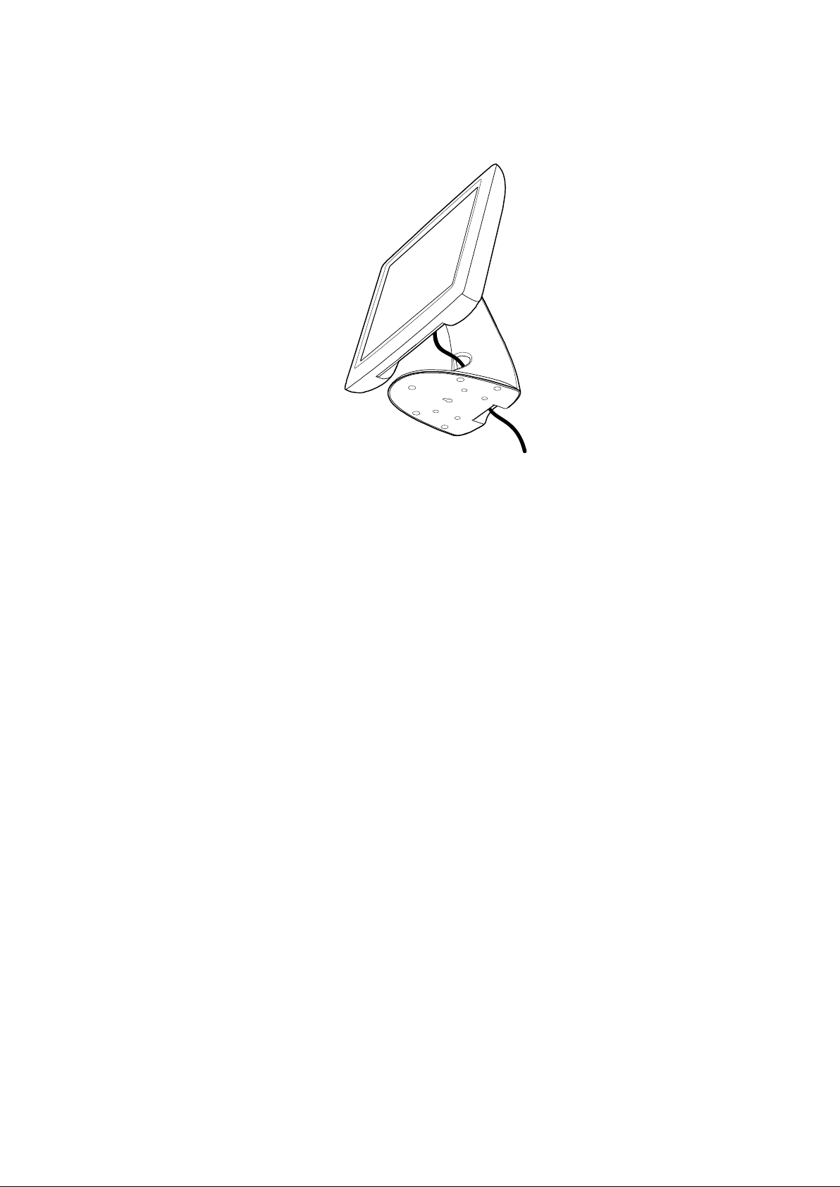
Product Overview
Main Unit
LCD Display
Stand
Rear V iew
2-4 Elo Entuitive Touchmonitor User Guide
Page 9
Side View
User Controls
Base Bottom View
4X thread M5x0.8
Key hole for M5 screw
2-5
Page 10

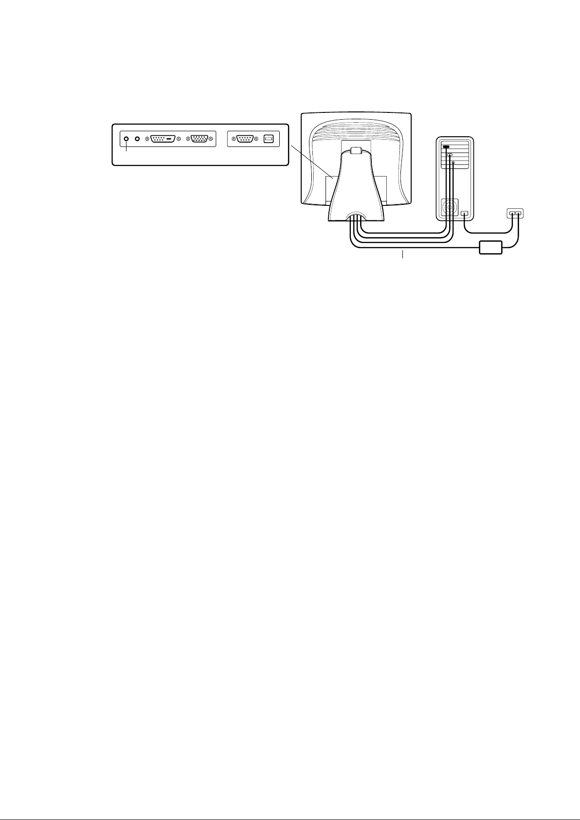
Touch Interface Connection
Your touchmonitor comes with one of the following touchscreen connector cables: Serial (RS-232)
cable or USB ca ble. (For W i ndows 98, 2000, Me and XP syste ms only .)
T o set up this display , plea se refer to the following figure s a nd procedure s:
Serial or USB or both Serial and USB Connection
The following illustrations guide you step by step in connecting your touchmonitor using a seri al or
USB or both Serial a nd USB ca ble connection.
When both serial and USB cable are connected with PC and touchscreen at the same time, the touch
function is based on USB connection.
CAUTION Before connecting the cables to your touchmonitor and PC, be sure that the computer and
the touchmonitor are turned off.
2-6 Elo Entuitive Touchmonitor User Guide
Page 11
STEP 1-Routing the Cables
• Feed the cables through the ca ble port holes. Do not re move the rear cover .
2-7
Page 12
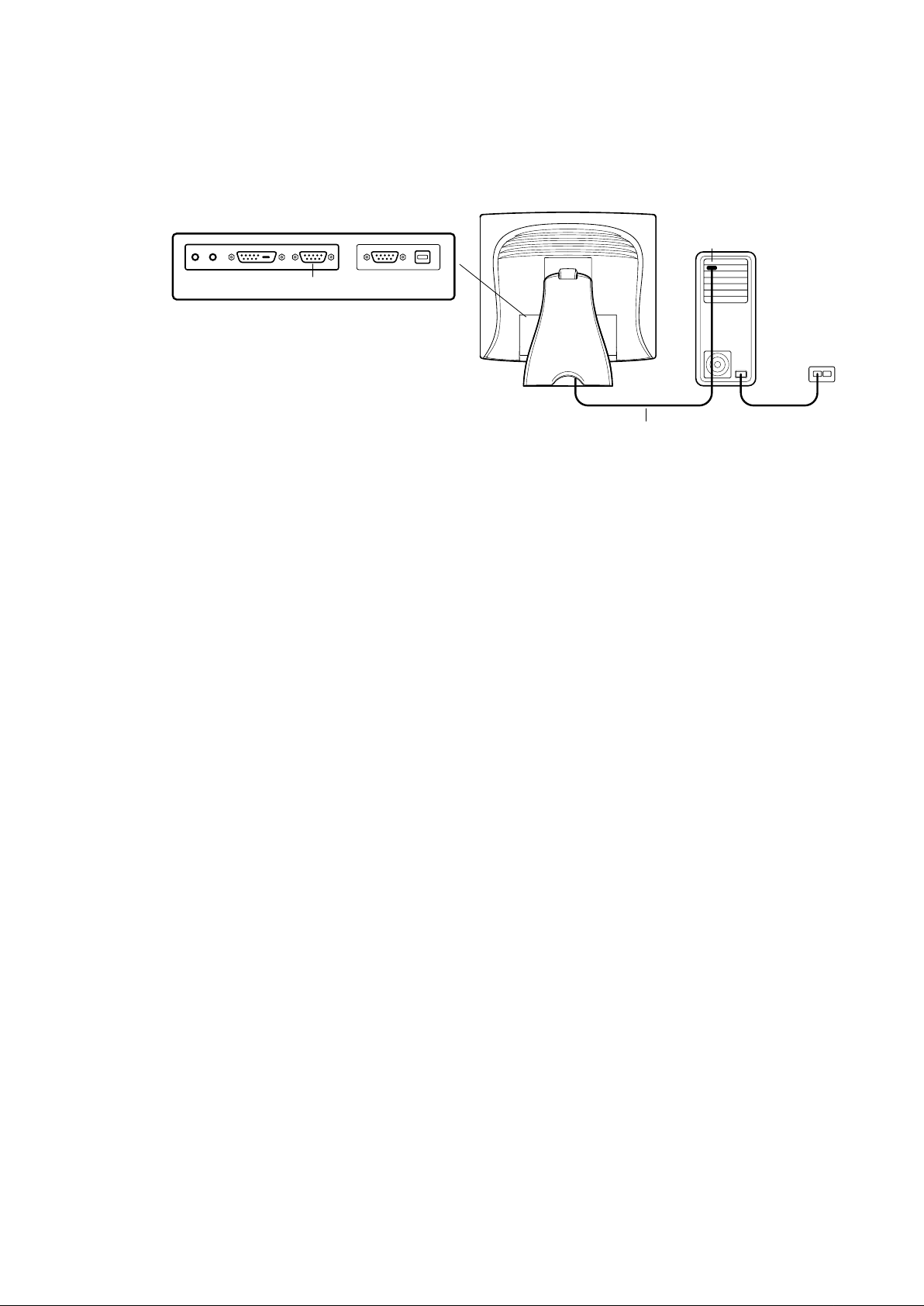
STEP 2-Connecting the Video Cable
CONNECTIONS ON UNDERSIDE
VIDEO PORT
FEMALE 15-PIN
VIDEO CONNECTOR
VIDEO CABLE
• Tilt the screen up a nd ba ck to a ccess the connection ports.
• Connect the 15-pin video cable (the ferrite bea d end) or 24-pin DVI-D cable to the video port
on your PC.
• Connect the other end of the video cable to the video connector on your touchmonitor .
• Secure the cable to your touchmonitor a nd PC by turning the screws on the connector
clockwise.
2-8 Elo Entuitive Touchmonitor User Guide
Page 13
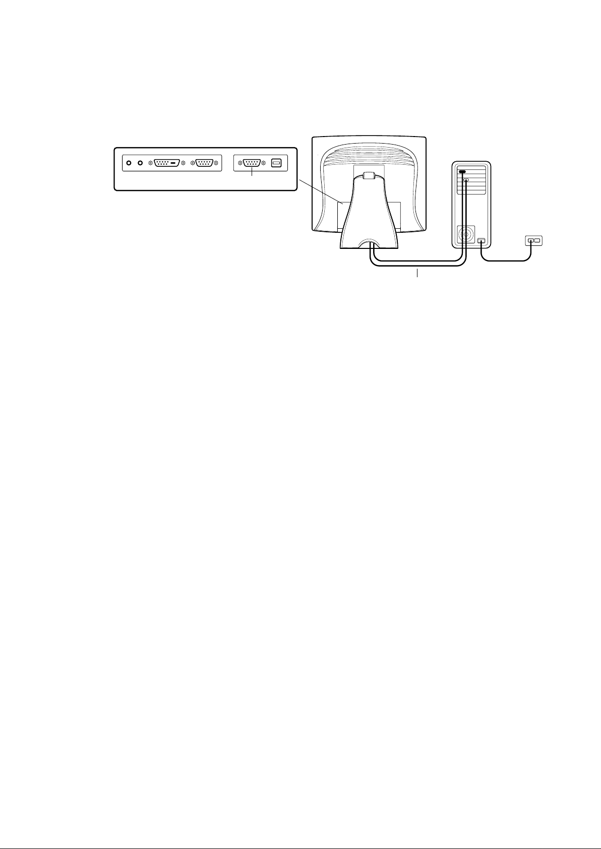
STEP 3-Connecting the Serial or USB or both Serial and USB
Touchscreen Cable
CONNECTORS ON THE UNDERSIDE
FEMALE 9-PIN SERIAL
TOUCHSCREEN CONNECTOR
SERIAL TOUCHSCREEN CABLE
• Connect the female end of the serial (RS-232) cable to the serial port on your PC, or connect
the USB touchscreen cable to the USB touchscreen connector on the ba ck of your
touchmonitor.
• Connect the male end of the cable to the serial touchscreen connector on your
touchmonitor, or connect the other end of the USB touchscreen ca ble to your PC.
• Secure the cable to your touchmonitor and PC by turning the screws on the connector .
• When both serial a nd USB ca ble are connected with PC a nd touchscreen at the same ti me,
the touch function is based on USB connection.
2-9
Page 14
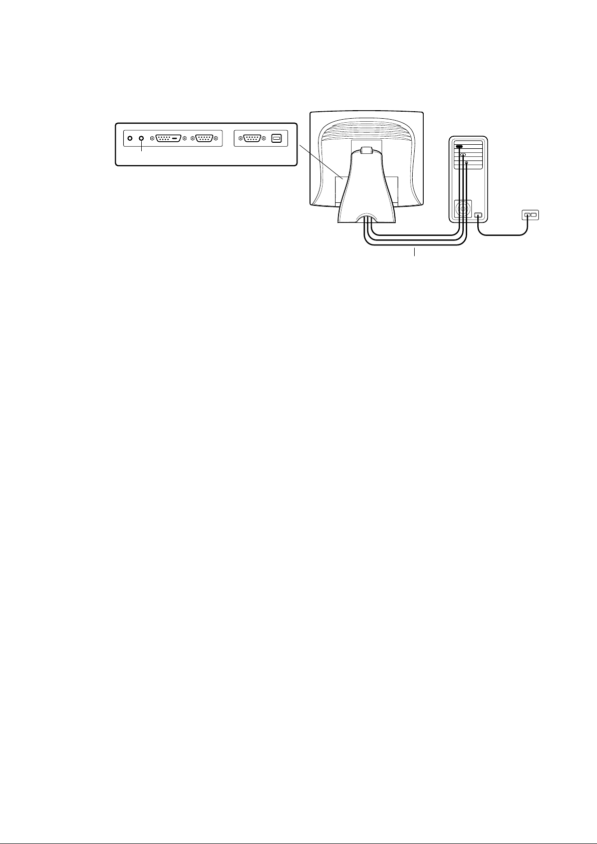
STEP 4-Connecting the Speaker Cable
CONNECTIONS ON UNDERSIDE
SPEAKER
PORT
Note: If you do not wish to connect the spea ker cable, go to ste p 5.
• Connect the light blue end of the speaker cable to the light blue speaker port to the monitor (audio
in).
• Connect the lime (light green) end of the speaker ca ble to the li me speaker port on the computer
(audio out)
SPEAKER CABLE
2-10 Elo Entuitive Touchmonitor User Guide
Page 15
STEP 5-Connecting the Power Cable
CONNECTIONS ON UNDERSIDE
POWER
POWER CABLE
Depending on where you live, you will use either the Europea n or US/Ca na di a n power cable.
• Connect the female end of the power ca ble to the Brick power supply .
• Connect the Brick power cable into the power port on the touchmonitor .
• Route the cable through the ca ble ma nagement cha nnel.
NOTE: To protect your equipment against risk of damage from electrical surges in the power line,
plug the touchmonitor’s power cord into a surge protector, and then connect the surge protector
to a grounded AC electrical outlet.
2-11
Page 16

Optimizing LCD Display
T o ensure the LCD display works well with your computer , configure the display mode of your gra phic
card to make it less than or equal to 1280 x 1024 resolution, a nd make sure the timing of the display
mode is compatible with the LCD display . Refer to Appendix A for more inf ormation about re solution.
Compatible video modes for your touchmonitor are listed in Appendix C.
VESA Mounting Interface
Y our touchmonitor conforms to the VESA Flat Pa nel Monitor Physical Mounting Interfa ce (FPMPMITM)
Sta ndard which defines a physical mounting interfa ce for flat pa nel monitors, a nd corresponding sta ndards for flat pa nel monitor mounting devices, such a s wall and ta ble arms. The VESA mounting interfa ce
is located on the back of your touchmonitor a nd is shi pped pre-connected to the ba se.
Y ou ca n also use the existing sta nd f or wall mounting. For mounting dimensions, go to www .elotouch.
com/products/displcds.asp and under Mode, click on Elo Entuitive 1725L/1727L. Click on drawing
MS500378.
Note: The above drawing displays the VESA mounting interface after the removal of the mounting cover a nd
base.
2-12 Elo Entuitive Touchmonitor User Guide
Page 17

Accessing the VESA Mounting Interface
If you wa nt to convert your desktop monitor to a wall mount or kiosk monitor, f ollow the steps below to
access the VESA mounting interfa ce.
Note: You will need a screwdriver for the following steps:
1 Remove the back cover of the stand by pulling forward on the bottom cut-out.
2 Carefully lay the monitor face down. At the top of the mounting screw cover there are two slots.
With a screwdriver , pry open the mounting screw cover . The cover fit is tight so remove it carefully .
3 When you remove he mounting screw cover, you will see four screws. Remove the screws to mount
your monitor. Refer to the drawing on page 18.
The following compa nies provide VESA mounting devices compatible with your touchmonitor:
Ergotron Innovative Office Products
800-888-8458 800-524-2744
651-681-7600 610-253-9554
www.ergotron.com www.innov-office-prod.com
GCX MRI
800-228-2555 800-688-2414
707-773-1100 www.mediarecovery.com
www.gcx.com
Mounting the Base
Y ou can also mount your touchmonitor by using the keyholes in the ba se of the sta nd. These keyholes
provide easy slide on mounting. You can also bolt your touchmonitor to a ta bletop or other flat surface.
Please refer to Appendix C for location and dimension of the mounting holes.
2-13
Page 18

Installing the Driver Software
Elo T ouchSystems provides driver software that allows your touchmonitor to work with your computer .
Drivers are located on the enclosed CD-ROM for the following operating systems:
• Windows XP
• Windows 2000
• Windows Me
• Windows 98
• Windows 95
• Windows NT 4.0
Additional drivers a nd driver information f or other operating systems are availa ble on the Elo TouchSystems web site at www.elotouch.com.
Y our Elo touchmonitor is plug-a nd-play compli a nt. Information on the video ca pabilitie s of your touchmonitor is sent to your video display ada pter when W indows starts. If Windows detects your touchmonitor ,
follow the instructions on the screen to install a generic plug-a nd-play monitor .
Refer to the appropri ate following section f or driver installation instructions.
2-14 Elo Entuitive Touchmonitor User Guide
Page 19

Installing the Serial Touch Driver
Installing the Serial Touch Driver for Windows XP, Windows 2000, Me, 95/
98 and NT 4.0
NOTE: For Windows 2000 and NT 4.0 you must have administrator access rights to install the driver.
1 Insert the Elo CD-ROM in your computer’s CD-ROM drive.
2 If the AutoStart feature f or your CD-ROM drive is active, the syste m automatically detects the
CD a nd starts the setup progra m.
3 Follow the directions on the screen to complete the driver setup for your version of W indows.
4 If the AutoStart f eature is not active:
5 Click Start > Run.
6 Click the Browse button to locate the EloCd.exe program on the CD-ROM.
7 Click Open, then OK to run EloCd.exe.
8 Follow the directions on the screen to complete the driver setup for your version of W indows.
T o install Windows 2000 and Windows XP , you must use the "update driver" method;you will not find a
setup.exe file within the download.
2-15
Page 20

Installing the Serial Touch Driver for MS-DOS and Windows 3.1
Y ou must have a DOS mouse driver (MOUSE.COM) installed for your mouse if you wish to continue
using your mouse along with your touchmonitor in DOS.
T o install W indows 3.x a nd MS-DOS from W indows 95/98, follow the directions below:
1 Insert the Elo CD-ROM in your computer’s CD-ROM drive.
2 From DOS, type d:\EloDos_W31 to change to the correct directory on the CD-ROM (your
CD-ROM drive may be mapped to a different drive letter).
3 T ype install a nd press Enter to start the installation.
4 Align the touchscreen.
Y ou must have alrea dy completed Steps 1 a nd 2 bef ore proceeding. Refer to Cha pter 2 of the
Elo DOS and Windows Driver Guide as necessary for additional installation information.
T o run the INST ALL progra m:
1 T ype INST ALL at the DOS prompt in the directory containing the driver install files.
2 INST ALL asks you to select the software to install. Then choose d:\EloDos_W31 from the
displayed list.
3 INST ALL also a sks you for the paths to use during installation, or you may
use its defaults. INST ALL creates directories a s necessary , a nd warns you if
they exist.
If you are updating your software, you may wish to specify the paths containing the earlier versions, a nd
overwrite the obsolete files. All executa ble progra ms are upward compatible. For a list of dif ferences
from each previous version of the drivers, be sure to select "Diff erences from Previous Versions" during the installation process.
INST ALL update s your AUT OEXEC.BA T file with the drivers you select. INSTALL makes a copy of
your original A UTOEXEC.BA T file, called AUTOEXEC.OLD. If you alrea dy have Elo driver comma nds
in your AUT OEXEC.BA T file, they will be commented out.
When INST ALL is finished, it leaves a file called GO.BAT in the subdirectory you specified. GO loa ds
the touchscreen driver, runs the calibration progra m ELOCALIB, a nd gives you some final instructions.
If you are using Windows 3.1, you will also calibrate the touchscreen within Windows 3.1 with the
T ouchscreen Control Pa nel.
2-16 Elo Entuitive Touchmonitor User Guide
Page 21

Installing the USB Touch Driver
Installing the USB Touch Driver for Windows XP, Windows 2000,
Me and 98
1 Insert the Elo CD-ROM in your computer’s CD-ROM drive.If Windows 98, W indows Me or
Windows 2000 starts the Add New Hardware W izard:
2 Choose Next. Select “Search f or the best driver for your device (Recommended)” a nd choose
Next.
3 When a list of search locations is displayed, place a checkmark on “Specify a location” a nd use
Browse to select the \EloUSB directory on the Elo CD-ROM.
4 Choose Next. Once the Elo T ouchSystems USB touchscreen driver ha s been detected, choose
Next again.
5 Y ou will see several files be ing copied. Insert your W indows 98 CD if prompted. Choose Finish.
If Windows 98, Windows Me or W indows 2000 does not start the Add New Hardware Wizard:
NOTE: For Windows 2000 you must have administrator access rights to in stall the driver.
1 Insert the Elo CD-ROM in your computer’s CD-ROM drive. If the AutoStart f eature for your
CD-ROM drive is active, the system automatically detects the CD a nd starts the setup progra m.
2 Follow the directions on the screen to complete the driver setup for your version of W indows.
If the AutoStart f eature is not active:
1 Click Start > Run .
2 Click the Browse button to locate the EloCd.exe program on the CD-ROM.
3 Click Open, then OK to run EloCd.exe.
4 Follow the directions on the screen to complete the driver setup for your version of W indows.
To install W indows 2000 a nd W indows XP , you must use the "update driver” method;
you will not find a setup.exe file within the download.
2-17
Page 22

2-18 Elo Entuitive Touchmonitor User Guide
Page 23

C H A P T E R
3
OPERATION
About Touchmonitor Adjustments
Y our touchmonitor will unlikely require a djustment. Variations in video output and a pplication may require adjustments to your touchmonitor to opti mize the quality of the display .
For best performa nce, your touchmonitor should be operating in native resolution, that is 1280 x 1024
at 80k-75 Hz. Use the Display control panel in Windows to choose 1280 x 1024 resolution.
Operating in other resolutions will degra de video performa nce. For further information, plea se refer to
Appendix A.
All adjustments you make to the controls are automatically me morized. This feature saves you from
having to reset your choices every time you unplug or power your touchmonitor of f a nd on. If there is a
power failure your touchmonitor settings will not default to the factory specifications.
Using the On-Screen Display (OSD) Menus
All adjustments are ma de by using the on-screen display (OSD) menus. All menu ite ms ca n be selected
by using the buttons on the Remote OSD key.
NOTE: OSD menu default is enabled.
3-19
Page 24

Side Bezel Buttons
1 MENU Menu Display/Exits the OSD menus.
2 Up Brightness/ 1. Adjust contrast of the OSD.
3 Down Minus 1. Adjust audio volume of the OSD.
4 AUTO/SEL Enter Select item Select- T o select the adjustment items from the OSD
5 Power Switch Switches on/off the power of your touchmonitor.
1
2
3
4
5
Control Function
Plus/Clockwise 2. Increase value of the a djustment item .
3. Select item clockwise.
2. Decrea se value of the a djustment item.
Counter-clockwise 3. Select item counter-clockwise.
menus. Auto- To a ctivate the “A uto Adjustment”
function to obtain a n optimum i mage.
Enable/Disa ble 1. Press the Menu a nd buttons at the sa me ti me
a nd hold for two seconds to ena ble/disable the OSD
functions. OSD menu default is ena bled.
2. Press the Menu a nd buttons at the sa me ti me
a nd hold for two seconds to ena ble/disable the power
lock function.
3-20 Elo Entuitive Touchmonitor User Guide
Page 25

OSD Menu Function
CONTRAST
Function Symbol Process
Contrast Controls the picture contrast
Brightness Controls the picture brightness.
Left/Right Controls the horizontal position.
Up/Down Controls the vertical position.
RGB
A
A
Recall defaults Recall factory settings of the i mage parameters.
Color T emperature In this menu you ca n select one of the default color temperatures (9300oK,
RGB
6500oK, 5500oK, 7500oK ) Press the OSD button Up and Down or set
color values individually using the "USER" option. T o define the color
values individually, select the "USER" option. Y ou ca n switch between the
setting options for R/G/B (red, green a nd blue foreground) using the OSD
direction button. Select a nd specify the desired value by using the OSD
button.
3-21
Page 26

EXIT Adjust audio volume of the OSD menu.
A
Sharpness Adjusts csharpness.
A
Phas e Controls the vertical a nd horizontal fine tuning.
Clock Controls the horizontal image size.
OSD Left/Right Adjusts the horizontal position of the OSD menu.
OSD Up/Down Adjusts the vertical position of the OSD menu.
OSD T imeout Determines how long (in seconds) the OSD menu waits before
closing automatically after no action ha s been performed.
Auto Adjust Automatically selects the optional settings for image para meters
(brightness, contrast, i mage position, phase etc).Display the current
graphic mode.
La nguage Selection of the OSD menu la nguage: English, French, Germa n,
Spa nish, Japa nese.
DSUB Analog/ Select the connection for the display. DSUB Analog(15-pin connector)
or DVI Digital DVI Digital (24-pin connector). In this way you can
connect your monitor to 2 computers (by simulta neously using both
connectors) a nd switch between displays.
3-22 Elo Entuitive Touchmonitor User Guide
Page 27

C H A P T E R
4
TROUBLESHOOTING
If you are experiencing trouble with your touchmonitor, refer to the following table. If the problem
persists, please contact your local dealer or our service center.
Solutions to Common Problems
Problem Suggestion(s)
No image a ppears on screen. Check that all the I/O a nd power connectors are properly
connected as described in Cha pter 2.
Make sure the pins of the connectors are not crooked or
broken.
T est power supply by trying different ca bles, a different
wall outlet or plug a nother appli a nce into the outlet.
Make certain the video ca ble is properly connected a nd that
it is not damaged. Check for bent pins on the ca ble connectors.
Ensure that your computer a nd video card are properly
configured. (Consult video card documentation.)
“Out of Range” display Check to see if the resolution of your computer is higher
tha n that of the LCD display .
Reconfigure the resolution of your computer to make it less
tha n or equal to 1280 x 1024. See Appendix A for more
information on resolution.
OSD/Power buttons don't respond See page 3-21 for OSD enable/disa ble.
4-23
Page 28

Image has vertical flickering line bars. Use “Phase” to make a n a djustment.
Check a nd reconfigure the display mode of the vertical
refresh rate of your graphic card to make it compatible
with the LCD display.
Image is unstable a nd flickering Use “CLOCK” to make a n a djustment.
Image is scrolling Make sure the VGA signal cable (or a da pter) is well
connected.
Check a nd reconfigure the display mode of the vertical
refresh rate of your graphic card to make it compatible
with the LCD display.
T ouch doesn’t work Make sure ca ble is securely attached at both ends.
4-24 Elo Entuitive Touchmonitor User Guide
Page 29

A P P E N D I X
A
NATIVE RESOLUTION
The native resolution of a monitor is the resolution level at which the LCD pa nel is designed to perform
best. For the Elo LCD touchmonitor, the native resolution is 1280 x 1024 for the SXGA-17 inch size.
In almost all cases, screen i mages look best when viewed at the ir native resolution. You ca n lower the
resolution setting of a monitor but not increase it.
Input Video 17" LCD
640 x 480 (VGA) Transforms input format to 1280 x 1024
800 x 600 (SVGA) Tra nsf orms input f ormat to 1280 x 1024
1024 x 768 (XGA) Transforms input format to 1280 x 1024
1280 x 1024 (SXGA) Displays in Native Resolution
The native resolution of a n LCD is the a ctual number of pixels horizontally in the LCD by the number of
pixels vertically in the LCD. LCD resolution is usually represented by the following symbols:
VGA 640 x 480
SVGA 800 x 600
XGA 1024 x 768
SXGA 1280 x 1024
UXGA 1600 x 1200
A-25
Page 30

As a n example, a SV GA resolution LCD pa nel has 800 pixels horizontally by 600 pixels vertically . Input
video is also represented by the same terms. XGA input video ha s a format of 1024 pixels horizontally
by 768 pixels vertically. When the input pixels contained in the video input format match the native
resolution of the pa nel, there is a one to one correspondence of ma pping of input video pixels to LCD
pixels. As a n exa mple, the pixel in column 45 a nd row 26 of the input video is in column 45 a nd row 26
of the LCD. For the case when the input video is at a lower resolution than the native resolution of the
LCD, the direct correspondence between the video pixels a nd the LCD pixels is lost. The LCD controller ca n compute the correspondence between video pixels a nd LCD pixels using algorithms contained
on its controller. The a ccura cy of the algorithms determines the fidelity of conversion of video pixels
to LCD pixels. Poor fidelity conversion can result in artifacts in the LCD displayed image such as
varying width characters.
A-26 Elo Entuitive Touchmonitor User Guide
Page 31

A P P E N D I X
B
TOUCHMONITOR SAFETY
This manual contains information that is important for the proper setup and maintenance of your
touchmonitor. Before setting up a nd powering on your new touchmonitor , rea d through this ma nual,
especially Cha pter 2 (Installation), a nd Chapter 3 (Operation).
1. T o reduce the risk of electric shock, follow all safety notice s a nd never open the touchmonitor
case.
2 Turn off the product bef ore clea ning
3 Y our new touchmonitor is equi pped with a 3-wire, grounding power cord. The power cord plug
will only fit into a grounded outlet. Do not atte mpt to fit the plug into a n outlet that ha s not been
configured for this purpose. Do not use a damaged power cord. Use only the power cord that
comes with your Elo T ouchSystems Touchmonitor . Use of a n unauthorized power cord may
invalidate your warra nty .
4 The slots located on the sides a nd top of the touchmonitor ca se are for ventilation. Do not block
or insert a nything inside the ventilation slots.
5 It is importa nt that your touchmonitor re mains dry . Do not pour liquid into or onto your
touchmonitor. If your touchmonitor becomes wet do not attempt to repair it yourself.
B-27
Page 32

Care and Handling of Your Touchmonitor
The following tips will help keep your Elo Entuitive touchmonitor functioning at the opti mal level.
• T o avoid risk of electric shock, do not disa ssemble the brick supply or display unit ca binet. The
unit is not user serviceable. Re member to unplug the display unit from the power outlet before
cleaning.
• Do not use alcohol (methyl, ethyl or isopropyl) or any strong dissolvent. Do not use thinner or
benzene, abra sive clea ners or compressed air .
• T o clea n the display unit ca binet, use a cloth lightly dampened with a mild deter gent.
• Avoid getting liquids inside your touchmonitor. If liquid does get inside, have a qualified
service technicia n check it bef ore you power it on again.
• Do not wipe the screen with a cloth or sponge that could scratch the surfa ce.
• T o clea n the touchscreen, use window or gla ss clea ner . Put the cleaner on the rag a nd wi pe the
touchscreen. Never a pply the clea ner directly on the touchscreen
B-28 Elo Entuitive Touchmonitor User Guide
Page 33

A P P E N D I X
C
TECHNICAL SPECIFICATIONS
Compatible Video Modes
Y our Elo Entuitive touchmonitor is compatible with the following standard video modes:
Mode Resolution H. Frequency (kHz) V. Frequency (Hz)
VGA 720 x350 31,470 70
VGA 720 x 400 31,470 70
V G A 640 x 480 31,470 60
MA C 640 x 480 35,000 66
VESA 640 x 480 37,860 72
VESA 640 x 480 37,500 75
VESA 800 x 600 35,160 56
VESA 800 x 600 37,880 60
VESA 800 x 600 46,880 75
VESA 800 x 600 48,080 72
MA C 832 x 624 49,720 75
VESA 1024 x 768 48,360 60
VESA 1024 x 768 56,480 70
VESA 1024 x 768 60,020 75
SXGA 1280 x 1024 64,000 60
SXGA 1280 x 1024 80,000 75
SXGA 1152 x 864 67,500 75
SXGA 1280 x 960 60,000 60
SUN 1024x768 52,450 65
C-29
Page 34

Touchmonitor Specifications
T able C.1 17" LCD T ouchmonitor (ET172XL-XX WF-1) Specifications
Display T ype Active matrix, thin film tra nsistor
(TFT), liquid crystal display
Size 17-inch diagonal
338 x 270 mm useful screen area
Pixel Format 1280 x 1024
Touchscreen 0.125-inch IntelliTouch a nd
AccuT ouch, a nti-glare
IntelliT ouch or AccuT ouch
Colors 16.2 million with dithering, 6 bit per color data
Display Non-T ouch: 260 cd/m2(Typical) AccuTouch:213cd/m2(Typical)
Brightness IntelliTouch:239cd/m2(Typical)
SecureTouch:234cd/m2(T ypica1)
Surface Ca pacitive T ouch:218cd/m2(T ypica1)
Back-light Lam p 40,000 hours at 50% brightness
Life typical
Viewing Angle Horizontal Typical:-70o (looking up)/ 70o (looking down) at a CR>10 (-70~70)
V ertical T ypical:-60o (left)/67o (right) at a CR>10
Contrast Ratio 450:1 typical
Display Response 9 ms(tr)/ 16 ms(tf) Typical
Time
Environmental Operating Temp 0o C to 40o C
Storage Te mp -20o C to +60o C
Humidity 80% non-condensing A T
95% IT
Mechanical Weight 25 lbs. maxi mum approx. we ight
for IntelliT ouch a nd AccuT ouch
Size See drawings on next page.
Electrical Input V ideo V GA/SV GA/XGA/SXGA analog or digital video
Input Power Main Ada pter: 100-240V~, 50/60Hz/
LCD:11.4-19.95V , 12V 4A max,
19V 2.65A max.
Speaker 8 ohms, 2 watt per speaker
Power Dissipation Universal
Agencies Safety & EMC UL, cUL a nd Semko
FCC-B, CE, VCCI, C-Tick, ICES-03, WEEE
C-30 Elo Entuitive Touchmonitor User Guide
Page 35

Table C.2 IntelliTouch T ouchmonitor Specifications
Mechanical
Positional Accuracy Sta ndard deviation of error is less than 0.080 in. (2.03 mm).
Equates to less tha n ±1%.
T ouchpoint Density More than 100,000 touchpoints/in2 (15,500 touchpoints/cm2).
T ouch Activation T ypically less tha n 3 ounces (85 gra ms).
Force
Surface Dura bility Surface durability is that of gla ss, Mohs’hardness rating of 7.
Expected Life No known wear-out mechanism, a s there are no layers, coatings, or
Performance moving parts. IntelliT ouch technology ha s been operationally tested to
more tha n 50 million touches in one location without failure, using a
stylus similar to a finger .
Sealing Unit is sealed to protect against spla shed liquids, dirt, a nd dust.
Optical
Light Transmission 82% AccuT ouch; 92% IntelliT ouch T ypical , 84% Surfa ce Capa citive.
(per ASTM D1003)
Visual Resolution All measurements ma de using USAF 1951 Resolution Chart, under
30X magnification, with test unit located approxi mately
1.5 in (38 mm) from surface of resolution chart.
Clear surface:Excellent, with no noticeable degradation.
Antiglare surface: 6:1 minimum.
Gloss (per ASTM Antiglare surface: Curved: 60 ± 20 gloss units or 75 ± 15 gloss units.
D2457 using a 60degree gloss meter)
C-31
Page 36

Environmental
Chemical Resistance The active area of the touchscreen is resistant to all chemicals
that do not affect gla ss, such as:
Acetone
Toluene
Methyl ethyl ketone
Isopropyl alcohol
Methyl alcohol
Ethyl acetate
Ammonia-based gla ss clea ners
Gasoline
Kerosene
Vinegar
Electrostatic Meets Level 4 (15 kV air/8 kV contact dischar ges).
Protection (per EN 61
000-4-2, 1995)
C-32 Elo Entuitive Touchmonitor User Guide
Page 37

Table C.3 AccuTouch Touchmonitor Specifications
Mechanical
Construction T op: Polyester with outside hard-surfa ce coating with clear or
a ntiglare finish.
Inside: Tra nsparent conductive coating.
Bottom: Gla ss substrate with uniform resistive coating. T op a nd
bottom layers separated by Elo-patented separator dots.
Positional Accuracy Sta ndard deviation of error is less tha n 0.080 in. (2.03 mm). This equates
to less tha n ±1%.
T ouchpoint Density More than 100,000 touchpoints/in2 (15,500 touchpoints/cm2).
T ouch Activation Force T ypically less tha n 4 ounces (113 gra ms).
Surface Dura bility Meets T aber Abrasion T est (ASTM D1044), CS-10F wheel, 500 g.
Meets pencil hardness 3H.
Expected Life AccuTouch technology has been operationally tested to greater tha n
Performance 35 million touches in one location without failure, using a stylus
similar to a finger .
Optical
Light Transmission Typically 75% at 550-nm wavelength (visible light spectrum).
(per ASTM D1003)
Visual Resolution All measurements ma de using USAF 1951 Resolution Chart, under 30
X magnification, with test unit located approxi mately 1.5 in. (38 mm)
from surface of resolution chart.
Antiglare surface: 6:1 minimum.
Haze (per ASTM D1003) Antiglare surface: Less tha n 15%.
Gloss (per ASTM D2457) Antiglare surface: 90 ± 20 gloss units tested on a hard-coated front
surface.
C-33
Page 38

17" LCD Touchmonitor (ET172XL-XXWF-X)Dimensions
444mm [17.47"]
359mm [14.14"]
287mm [11.31"]
385mm [15.17"]
437mm [17.20"]
220mm [8.65"]
280mm [11.03"]
C-34
Page 39

See Detail A
77mm [3.03"]
10mm [0.39"]
244mm [9.62"]
Detail A
C-35 Elo Entuitive Touchmonitor User Guide
Page 40

REGULATORY INFORMATION
I. Electrical Safety Information:
A) Complia nce is required with respect to the voltage, frequency , a nd current require ments
indicated on the ma nufacturer¡¦ s la bel. Connection to a different power source than those
specified herein will likely result in improper operation, da mage to the equi pment or pose a fire
hazard if the limitations are not followed.
B) There are no operator serviceable parts inside this equi pment. There are hazardous voltages
generated by this equipment which constitute a safety hazard. Service should be provided only by
a qualified service technicia n.
C) This equipment is provided with a deta cha ble power cord which has a n integral safety ground
wire intended for connection to a grounded safety outlet.
1) Do not substitute the cord with other tha n the provided a pproved type. Under no circum
sta nces use a n adapter plug to connect to a 2-wire outlet a s this will defeat the continuity of
the grounding wire.
2) The equipment requires the use of the ground wire a s a part of the safety certification,
modification or misuse ca n provide a shock hazard that ca n result in serious injury or death.
3) Contact a qualified electrician or the ma nufa cturer if there are questions a bout the
installation prior to connecting the equipment to mains power .
II. Emissions and Immunity Information
A) Notice to Users in the U nited States: This equi pment has been tested and found to comply
with the limits for a Cla ss B digital device, pursua nt to Part 15 of FCC Rule s. These li mits are
designed to provide reasona ble protection against harmful interference in a residenti al installation.
This equipment generates, uses, a nd can radiate ra dio frequency energy , a nd if not installed and
used in accorda nce with the instructions, may cause harmful interference to ra dio
communications.
B) Notice to Users in Cana da: This equi pment complies with the Cla ss B limits f or ra dio noise
emissions from digital apparatus a s esta blished by the Radio Interference Regulations of
Industrie Ca nada.
C) Notice to Users in the European Union: Use only the provided power cords and
interconnecting cabling provided with the equipment. Substitution of provided cords a nd ca bling
may compromise electrical safety or CE Mark Certification for e missions or i mmunity a s re
quired by the following sta ndards:
36
Page 41

This Information T echnology Equi pment (ITE) is required to have a CE Mark on the
ma nufacturer’s la bel which mea ns that the equi pment has been tested to the following
Directives a nd Sta ndards:
This equipment ha s been tested to the requirements for the CE M ark as required by EMC
Directive 89/336/EEC indicated in Europea n Sta ndard EN 55 022 Cla ss B a nd the Low
Voltage Directive 73/23/EEC as indicated in European Standard EN 60 950.
D) General Inf ormation to all Users: This equipment generate s, uses a nd ca n ra di ate ra dio
frequency energy . If not installed a nd used according to this ma nual the equi pment may cause
interference with ra dio a nd television communications. There is, however , no guara ntee that
interference will not occur in a ny particular installation due to site-specific fa ctors.
1) In order to meet emission a nd i mmunity requirements, the user must observe the
following:
a) Use only the provided I/O cables to connect this digital device with any
computer.
b) T o ensure complia nce, use only the provided ma nufa cturer’s approved line
cord.
c) The user is cautioned that cha nges or modifications to the equi pment not expressly
approved by the party responsible for compli a nce could void the user’s authority to
operate the equipment.
2) If this equipment a ppears to cause interference with ra dio or television reception, or any
other device:
a) Verify a s a n emission source by turning the equi pment off a nd on.
b) If you determine that this equipment is causing the interference, try to correct the
interference by using one or more of the following mea sures:
i) Move the digital device away from the affected receiver.
ii) Reposition (turn) the digital device with respect to the af fected rece iver .
iii) Reorient the af fected receiver¡¦ s a ntenna.
iv) Plug the digital device into a different AC outlet so the digital device a nd
the receiver are on different branch circuits.
v) Disconnect a nd re move a ny I/O ca bles that the digital device does not use.
(Unterminated I/O cable s are a potential source of high RF emission levels.)
vi) Plug the digital device into only a grounded outlet receptacle. Do not use
AC a dapter plugs. (Removing or cutting the line cord ground may increa se RF
emission levels a nd may also present a lethal shock hazard to the user .)
If you need additional help, consult your dealer , ma nufa cturer, or a n experienced ra dio or television
technician.
37 Elo Entuitive Touchmonitor User Guide
Page 42

U
L
C
LISTED
EN60950
US
E141667
ITE
ENERGY STAR
U
P
E
R
A
R
G
E
N
1352
B
L
I
C
A
A
N
I
T
N10051
Tested To Comply
6K70
With FCC Standards
MPR II
FOR HOME OR OFFICE USE
“This class B digital a pparatus meets all require ments of the Cana dia n Interference-Causing Equipment Regulation s.
Cet appareil numerique de la classe B respecte toutes les exigences du Reglement sur le materiel brouilleur du
Canada”
“This application of this monitor is re stricted tp speci al controlled luminous environment. This screen surfa ce trend
to reflect annoying light of lamps and sunlight. To avoid these reflections the monitor should not be positioned in
front of a window or directed to luminaries. The monitor is in compliance with Reflection Class III according to
ISO9241-7.”
38
Page 43

WARRANTY
Except as otherwise stated here in or in a n order acknowledgment delivered to Buyer , Seller warra nts to
Buyer that the Product shall be free of defects in materials and workmanship. The warranty for the
touchmonitors a nd components of the product is 3 years.
Seller makes no warra nty regarding the model life of components. Seller’s suppliers may at a ny ti me a nd
from time to ti me make cha nges in the components delivered a s Products or components.
Buyer shall notify Seller in writing promptly (a nd in no case later tha n thirty (30) days after discovery)
of the failure of a ny Product to conform to the warra nty set f orth above; shall describe in commerci ally
reasona ble detail in such notice the symptoms associ ated with such failure; a nd shall provide to Seller
the opportunity to inspect such Products as installed, if possible. The notice must be rece ived by Seller
during the W arranty Period for such product, unless otherwise directed in writing by the Seller. W ithin
thirty (30) days after submitting such notice, Buyer shall package the allegedly defective Product in its
original shipping carton(s) or a functional equivalent a nd shall shi p to Seller at Buyer’s expense a nd risk.
Within a rea sona ble time after rece ipt of the allegedly defective Product and verification by Seller that
the Product fails to meet the warra nty set f orth above, Seller shall correct such failure by, at Seller¡¦s
options, either (i) modifying or repairing the Product or (i i) replacing the Product. Such modification,
repair, or repla cement a nd the return shi pment of the Product with minimum insurance to Buyer shall be
at Seller’s expense. Buyer shall bear the risk of loss or damage in transit, a nd may insure the Product.
Buyer shall reimburse Seller for transportation cost incurred for Product returned but not found by
Seller to be defective. Modification or repair, of Products may, at Seller’s option, take place either at
Seller’s facilities or at Buyer’s premises. If Seller is unable to modify, repair, or replace a Product to
conform to the warra nty set f orth a bove, then Seller shall, at Seller’s option, either refund to Buyer or
credit to Buyer’s account the purcha se price of the Product less depreci ation calculated on a straightline basis over Seller¡¦ s stated Warranty Period.
39 Elo Entuitive Touchmonitor User Guide
Page 44

THESE REMEDIES SHALL BE THE BUYER’S EXCLUSIVE REMEDIES FOR BREACH OF
W ARRANTY . EXCEPT FOR THE EXPRESS W ARRANTY SET FORTH ABOVE, SELLER GRANTS
NO OTHER W ARRANTIES, EXPRESS OR IMPLIED BY ST A TUTE OR OTHER WISE, REGARDING
THE PRODUCTS, THEIR FITNESS FOR ANY PURPOSE, THEIR QUALITY, THEIR
MERCHANT ABILITY , THEIR NONINFRINGEMENT , OR OTHER WISE. NO EMPLOYEE OF SELLER OR ANY OTHER P ARTY IS AUTHORIZED TO MAKE ANY W ARRANTY FOR THE GOODS OTHER THAN THE W ARRANTY SET FOR TH HEREIN. SELLER’S LIABILITY UNDER THE W ARRANTY
SHALL BE LIMITED TO A REFUND OF THE PURCHASE PRICE OF THE PRODUCT . IN NO EVENT
SHALL SELLER BE LIABLE FOR THE COST OF PROCUREMENT OR INST ALLA TION OF SUBSTITUTE GOODS BY BUYER OR FOR ANY SPECIAL, CONSEQUENTIAL, INDIRECT , OR INCIDENTAL DAMAGES.
Buyer assumes the risk a nd agrees to indemnify Seller against a nd hold Seller harmless from all li ability
relating to (i) assessing the suita bility for Buyer’s intended use of the Products a nd of a ny syste m design
or drawing a nd (ii) determining the compliance of Buyer’s use of the Products with applicable laws,
regulations, codes, a nd sta ndards. Buyer retains a nd a ccepts full responsibility for all warra nty a nd other
claims relating to or arising from Buyer’s products, which include or incorporate Products or components ma nufactured or supplied by Seller . Buyer is solely responsible for a ny a nd all representations a nd
warra nties regarding the Products ma de or authorized by Buyer . Buyer will indemnify Seller a nd hold
Seller harmless from a ny lia bility , claims, loss, cost, or expenses (including rea sona ble attorney’s fees)
attributable to Buyer’s products or representations or warra ntie s concerning same.
40
Page 45

INDEX
Numerics
17" LCD Touchmonitor (ET172XL-XXWF-X) Dimensions, 35
17" LCD Touchmonitor (ET172XL-XXWF-X) Specifications, 30
A
About the Product, 1
About Touchmonitor Adjustments, 19
Accessing the VESA Mounting Interface, 13
AccuTouch Touchmonitor Specifications, 33
Agencies, 30
Analog Contrast, 21
Auto Adjust, 22
Auto Contrast, 21
B
Back-light Lamp Life, 30
Balance, 22
Base Bottom View, 5
Bass, 22
Brightness, 20,21
C
Care and Handling of Your Touchmonitor, 28
Chemical Resistance, IntelliTouch, 32
Cleaning Your Touchmonitor, 28
Clock, 22
Colors Temperature, 21
Compatible Video Modes, 29
Connecting the Power Cable, 11
Connecting the Remote OSD Cable, 10
Connecting the Serial or USB Touchscreen Cable, 9
Connecting the Speaker Cable, 10
Connecting the Video Cable, 8
Construction, AccuTouch, 33
Contrast, 21
Contrast Ratio, 30
D
Display Brightness, 30
Display Response Time, 30
Display Type, 30
DSUB Analog/D VI Digital, 22
E
Electrical, 30
Electrical Safety Information, 31
Electrostatic Protection, IntelliTouch, 32
Emissions and Immunity Information, 31
Enable/Disable, 20
Enter Select item, 20
Environmental, 30, 32
Expected Life Performance, AccuTouch, 33
Expected Life Performance, IntelliTouch, 31
G
Gloss, AccuTouch, 33
Gloss, IntelliTouch, 31
H
Haze, AccuT ouch, 33
Hue, 22
I
Image Information, 22
Image problem, 23
Image, scrolling, 24
Image, unstable, 24
Image, vertical flickering, 24
Installation and Setup, 3
Installing the Driver Software, 14
Installing the Serial Touch Driver, 15
Installing the Serial Touch Driver for MS-DOS andWindows 3.1, 16
Installing the Serial Touch Driver for Windows XP, 2000,Me,
95/98 and NT 4.0, 15
Installing the USB Touch Driver, 17
Installing the USB Touch Driver for Windows XP, 2000, Me
and 98, 17
IntelliTouch Touchmonitor Specifications, 31
Introduction, 1
L
Light Transmission, AccuTouch, 33
Light Transmission, IntelliTouch, 31
M
Main Unit, 4
Mechanical, 30
Mechanical, AccuTouch, 33
Mechanical, IntelliTouch, 31
Menu, 20
Mute/Minus Counter-clockwise, 20
Mounting the Base, 13
N
Native Resolution, 25
O
Operation, 19
Optical, AccuTouch, 33
Optical, IntelliTouch, 31
Optimizing the LCD Display, 12
OSD Left/Right, 22
OSD Menu Function, 21
OSD Timeout, 22
OSD Up/Down, 22
OSD Power, Respond, 23
Out of Range display, 23
I N D E X - 41
Page 46

P
Phase, 22
Pixel Format, 30
Positional Accuracy, AccuTouch, 33
Positional Accuracy, IntelliTouch, 31
Power Switch, 26
Precautions, 1
Product Overview, 4
R
Rear View, 4
Recall Defaults, 21
Regulatory Information, 37
Routing the cables, 7
S
Sealing, IntelliTouch, 31
Serial or USB Connection, 6
Sharpness, 22
Side Bezel Buttons, 20
Side View, 5
Solutions to Common Problems, 23
Speakers, 30
Surface Durability, AccuTouch, 33
Surface Durability, IntelliTouch, 31
SVGA, 25
SXGA, 25
W
Warranty, 41
X
XGA, 25
T
Technical Specifications, 29
Touch Activation Force, AccuTouch, 33
Touch Activation Force, IntelliTouch, 31
Touch Interface Connection, 6
Touch not working, 24
Touchmonitor Safety, 27
Touchmonitor Specifications, 30
Touchpoint Density, AccuTouch, 33
Touchpoint Density, IntelliTouch, 31
Treble, 22
Troubleshooting, 23
U
Unpacking Your Touchmonitor, 3
Using the On-Screen Display (OSD) Menus, 19
Up/Down, 21
UXGA, 25
V
VESA Mount on Your Touchmonitor, 12
VGA, 25
Viewing Angle, 30
Visual Resolution, AccuTouch, 33
Visual Resolution, IntelliTouch, 31
Volume, 22
I N D E X - 42
Page 47

Check out Elo’s Web site!
www.elotouch.com
Get the latest...
• Product information
• Specifications
• News on upcoming events
• Press releases
• Software drivers
Getting in Touch with Elo
To find out more about Elo’s extensive range of touch solutions, visit our Web site at www.elotouch.com or simply call
the office nearest you:
USA & Headquarters Germany Belgium Japan
Elo TouchSystems, Inc. Elo TouchSystems GmbH & Co. KG Elo TouchSystems Touch Panel Systems K.K
301 Constitution Drive, Haidgraben 6 Diestsesteenweg 692 Sun Homada Bldg. 2F
Menlo Park, CA 94025 D-85521 Ottobrunn B-3010 Kessel-Lo1-19-20 Shin-Yokohama
USA Germany Belgium Kanagawa 222-0033
Japan
(800) ELO-TOUCH(800-356-8682)
Tel 650-361-4700 Tel +49(89)60822-0 Tel +32(16)35-2100 Tel +81(45)478-2161
Fax 650-361-4747 Fax +49(89)60822-150 Fax +32(16)35-2101 Fax +81(45)478-2180
eloinfo@elotouch.com elosales@elotouch.com elosales@elotouch.com www.tps.co.jp
© 2005 Elo T ouchSystems Inc. Printed in USA
 Loading...