

Page 1
Page 2
Elo Entuitive Touchmonitor
User Guide
15" LCD Panel Mount Touchmonitor
1566L Series
Revision B
P/N 0085 31
Elo TouchSystems, Inc.
1-800-ELOTOUCH
www.elotouch.com
Page 3

Page 4

Copyright © 2001 Elo TouchSystems Inc. All Rights Reserved.
No part of this p ublic ation ma y be repr oduce d, tra nsmitte d, transc ribe d, stor ed in a ret rieval system,
or translated into any language or comput er language, in any form or by any means, including, but not
limited to, electronic, magnetic, optical, chemical, manual, or otherwise without prior written
permission of Elo Touch Systems.
Disclaimer
The informat ion in this docum ent is subje ct to change with out notice . Elo TouchSystems make s no
representations or warranties with respect to the contents hereof, and specifically disclaims any
implied warranti es of mer chanta bilit y or fitness for a parti cular purp ose. El o TouchSystems rese rves
the right to revise this publication and to make changes from time to time in the content hereof
withou t ob l igatio n of El o Touch S ys tems to notif y an y pe r s o n of such revi s io ns or ch an ges.
Trademark Acknowledgments
IntelliTouch, SecureTouch, AccuTouch, Entuitive, and MonitorMouse are trademarks of Elo
TouchSystems, Inc.
Other product names mentioned herein may be trademarks or registered trademarks of their
respective companies. Elo TouchSystems claims no interest in trademarks other than its own.
i
Page 5

ii
Page 6

Table of Contents
Chapter 1
Introduction 1
Precautions . . . . . . . . . . . . . . . . . . . . 1
About the Product . . . . . . . . . . . . . . . . . 1
Chapter 2
Installation and Setup 3
Unpacking Your Panel Mount
Touchmonitor . . . . . . . . . . . . . . . . . . 4
Product Overview . . . . . . . . . . . . . . . . . 5
Main Unit . . . . . . . . . . . . . . . . . . . . 5
Rear View . . . . . . . . . . . . . . . . . . . 5
Bottom View . . . . . . . . . . . . . . . . . . 6
Remote O SD with Ca b le Attachment . . . . . 6
Mounting Your Touchmonitor . . . . . . . . . . . 7
Connecting Your Touchmoni tor . . . . . . . . . . 8
Optimizing the LCD Display . . . . . . . . . . . 11
Installing the Driver Software . . . . . . . . . . 12
Installi ng th e Ser ia l Touch Driver. . . . . . . 13
Installin g the Serial T o uch Driver for Windo ws
2000, Me, 95/98 and NT 4.0 . . . . . . . 13
Installin g the Seri al Touch Driver for MS-DOS
and Windows 3.1 . . . . . . . . . . . . . 14
Chapter 3
Operati o n 15
About Touchmonitor Adjustments . . . . . . . . 15
Connecting the OSD Module . . . . . . . . . . 16
OSD Module Controls. . . . . . . . . . . . . . 17
Using the OSD Menus. . . . . . . . . . . . . . 18
Auto Adjustment . . . . . . . . . . . . . . . . . 18
First OSD Menu . . . . . . . . . . . . . . . . . 19
Contrast . . . . . . . . . . . . . . . . . . . 19
Horizontal Position . . . . . . . . . . . . . . 20
Vertical Position . . . . . . . . . . . . . . . 20
Horizontal Size . . . . . . . . . . . . . . . . 20
Tracking . . . . . . . . . . . . . . . . . . . 21
Second OSD Menu . . . . . . . . . . . . . . . 21
Display Mode. . . . . . . . . . . . . . . . . 22
OSD Off-Time . . . . . . . . . . . . . . . . 22
Language . . . . . . . . . . . . . . . . . . 22
Te xt-Graphic . . . . . . . . . . . . . . . . . 22
Reset . . . . . . . . . . . . . . . . . . . . . 22
Chapter 4
Troubleshooting 23
Solutions to Common Problems . . . . . . . . 23
Appendix A
Native Resol ution 25
Appendix B
T ouc hmonitor Safety 27
Care and Handling of Your Touchmonitor. . . . 28
Appendix C
Technical Sp ecification s 29
Compatibility Modes . . . . . . . . . . . . . . 29
Touchmonitor Specifications . . . . . . . . . . 30
15" LCD Touchmonitor (ET1566L)
Specifications . . . . . . . . . . . . . . . 30
AccuTou ch Touchscreen Specificat ions . . . 31
CarrollTouch Specifications . . . . . . . . . 32
15" LCD Panel Mount Touchmonitor
(ET1566L-XSWA-X) Dimensions . . . . . 34
Panel Cutout . . . . . . . . . . . . . . . . . 36
Regulatory Information 37
Warranty 41
Index 43
iii
Page 7

iv
Page 8

Congratulati ons on you r purchase of an El o TouchS ystems Entu itive LCD panel
mount touchmonitor. Your new high-resolution industria l touchmonitor
combines the reliable perf ormance of Elo’s touch technology with the late st
advances in LCD display design. This combination of features creates a natural
flow of information betwe en you and your touchmonitor.
Precautions
C HAPTER
1
C
HAPTER
1
I
NTRODUCTION
Follow all warnings, precautions and maintenance as recommended in this
user’s manual to maximize the life of your unit. See Appendix B for more
information on touchmon itor safety.
Abou t the Pr oduct
Your LCD panel mount Touc hmonitor is a 15" XGA TFT colo r di splay wit h the
following feature s:
• Direct analog RGB input
• 15.1" diagonal screen size
• 16.7 million displayable colors
• 1024 x 768 resolution
• XGA / SVGA / VGA / VESA / Mac compatible
• 24-60kHz horizontal sc an
• 56-85Hz high refresh rate
1-1
Page 9

• Auto adjustment capability
• High quality full scree n re- scaling
• Multilingual OSD menus in four languages: English, German, Spanish, and
Japanese
• Corded remote OSD controller
• VESA DDC 1/2B data communication
• VESA DPMS power saving
• VESA flat panel monitor physical mou nting interface (75mm)
• 19 inch computer hardware rack adaptor available. Contact the factory.
• Worldwide agency approvals that include UL*, CUL*, TÜV- Bauart, FCC,
CE, C-Tick , VCC I
• Certified by UL to NEMA 4, 4x and 12: ET1566L-7SWA-1*
• Designed to meet NEMA 4, 4x & 12: ET1566L-9SWA-1/5*
*ITE recognized component
For full Product Specif ications refer to Appendix C.
1-2 Elo Entuitive Touchmonitor User Guide
Page 10

C HAPTER
2
C
HAPTER
2
I
NSTALLATION AND
This chapter discusse s how to install your LCD panel mount touchmonitor and
how to install Elo TouchSyste ms driver software.
S
ETUP
2-3
Page 11
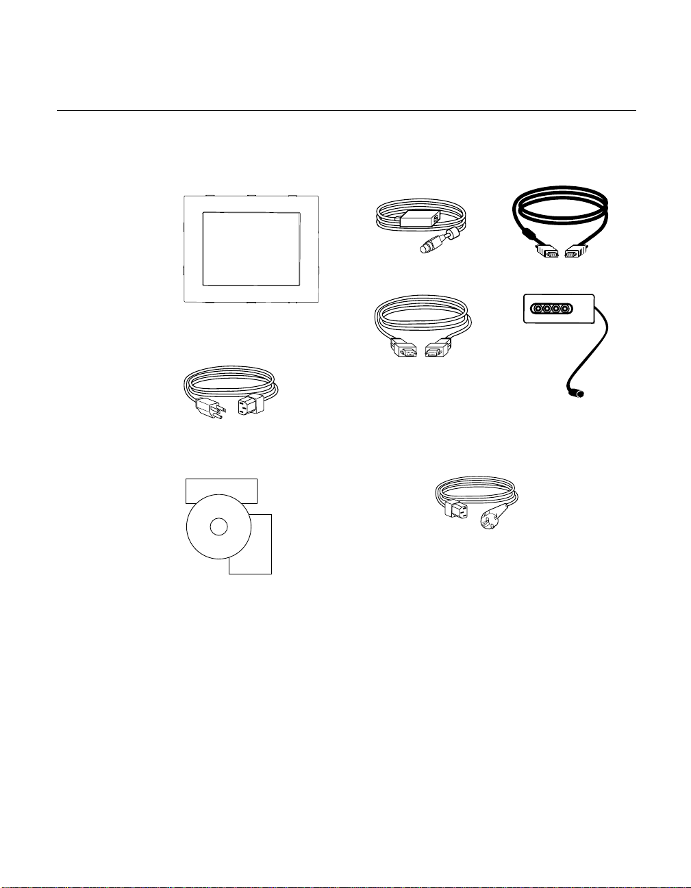
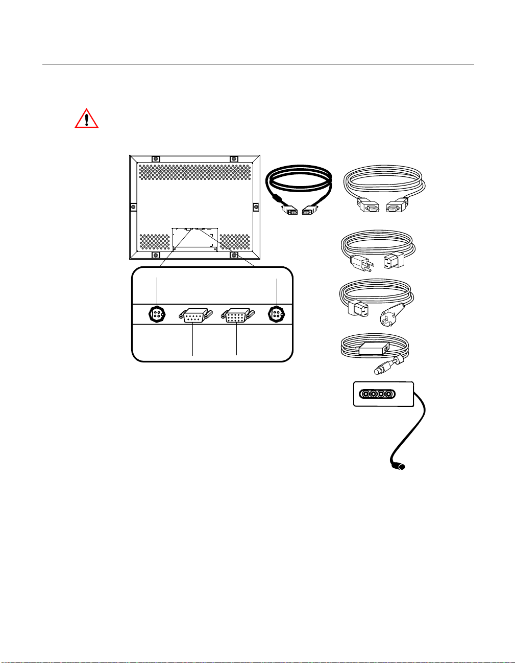
Unpacking Your Panel Mount Touchmo nitor
Check that the following 10 items are prese nt and in good condition:
Brick power supply
LCD Display
Serial touchscreen
cable
Monitor power cable (US/Canada)
Elo QuickStart
CD
Software
User
Guide
User’s Guide,
Quick Start Guide and software CD
Video cable
AUTO/SEL DOWN UP MENU
OSD module
European monitor power cable
(Note: shipments to the UK will
contain a UK power cord.)also
2-4 Elo Entuitive Touchmonitor User Guide
Page 12
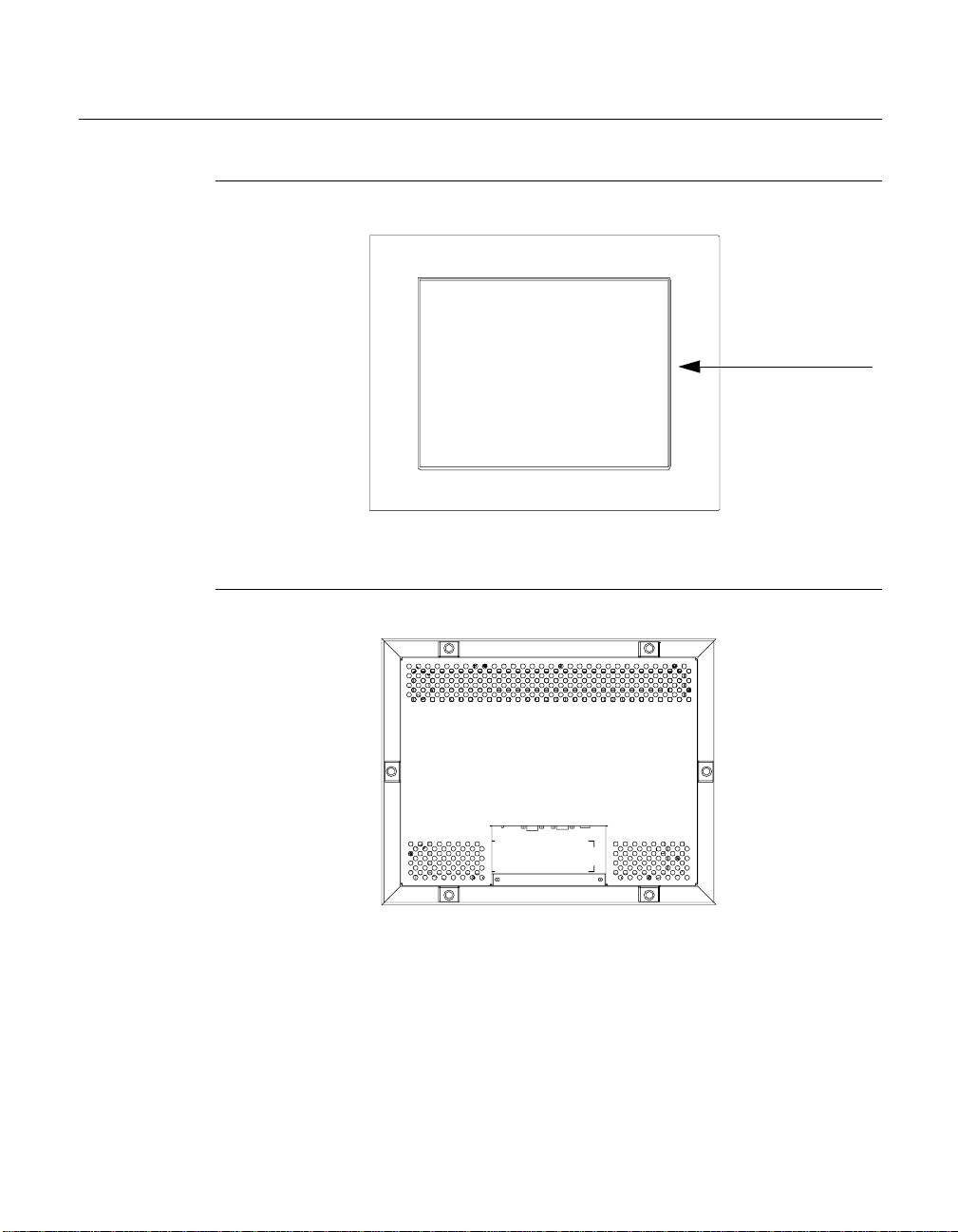
Prod uct O verview
Main Unit
Rear View
LCD Display
2-5
Page 13
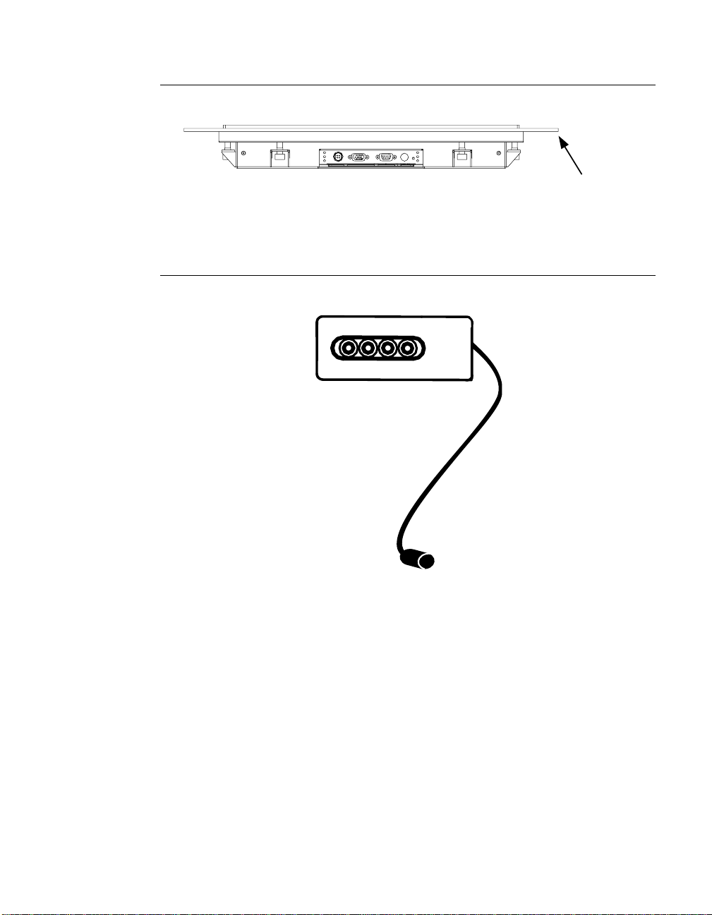
Bottom View
Remote OSD with C ab l e Attachment
AUTO/SEL DOWN UP MENU
Customer Panel
2-6 Elo Entuitive Touchmonitor User Guide
Page 14

Mounting Your T ouchmonitor
N
OTE
:
You will need a 6mm allen socket and torque wrench (Hex) to attach the mounting
brackets.
Your panel mount touchmonitor comes with 6 mounting brackets (and 6
screws). You will need 6 brackets to mount your touchmonitor. Two brackets
attach to the top and bottom and one on each side.
To mount your touchmonitor to a panel, follow the steps below:
1 Prepare the opening in the panel ( 307mm x 398.2mm/12.08" x 15.68"). See
page C-36. Mounting panel thickness must not exceed 13mm.
2 Disassemble the 6 brackets a nd NEMA frame.
3 Verify that your touchmonitor will clear the opening as you attempt to front
mount it. The opening will be covered by the bezel f l a nges.
4 Mount the touchmonitor from the front side of the opening in the supporting
panel and temporarily secure it.
5 From the back of the panel opening, slip the NEMA frame over the rear
cover. Attach the 6 brackets into the slots. Use 2 brackets on top and bottom
and 1 on each side.
6 To secure the touchmonitor , turn the screws clockwise until a firm contact is
made with the NEMA frame. To assure a “flat” mount, screws should be
tightened “cris-cross” and not sequentially, i.e. tighten the upper left corner
screw first then the lower right screw. To rq ue sc rew s to 35 in l bs. (4 Nm) .
2-7
Page 15
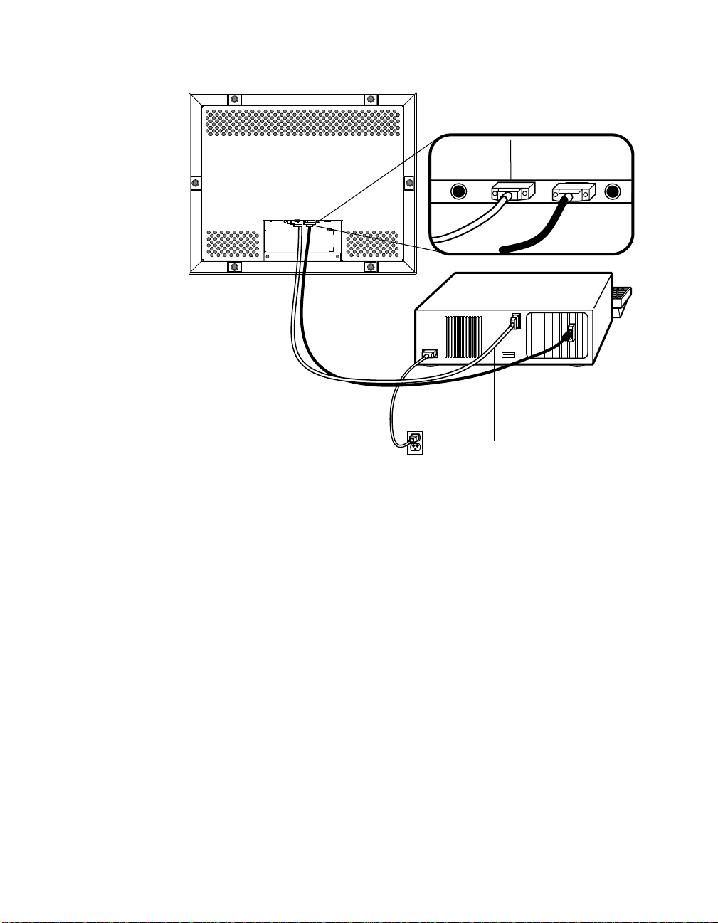
Conn ecting Your Touchmon itor
The following illust rations guide you step by step in connecting your
touchmonitor.
Before connecting the cables to your touchmonitor and PC, be sure that the computer
and the touchmonitor are turned off.
Video cable
OSD Module connector
Power
Serial cable
US
power cable
European
power cable
Serial
touchscreen
connector
Connections on underside
Female 15-pin
video
connector
2-8 Elo Entuitive Touchmonitor User Guide
AUTO/SEL DOWN UP MENU
Brick
power supply
Page 16
STEP 1-Connecting the Video Cable
Connections on underside
Female 9-pin serial
touchscreen
connector
Serial
touchscreen
cable
• Connect the 15-pin video cable (the ferrite bead end) to the video port on
your PC.
• Connect the other end of the video cable to the video connector on your
touchmonitor.
• Secure the cable to your touchmon itor and PC by turning the screws on the
connector clockwi se.
2-9
Page 17

STEP 2-Connecting the Serial Touchscreen Cable
Connections on underside
Female 9-pin Serial
touchscreen
connector
Serial
touchscreen
cable
• Connect the female end of the serial (RS-232) cable to the serial port on the
back of your PC.
• Connect the male e nd of th e cable to t he s erial t ouchsc reen conne ctor on your
touchmonitor.
• Secure the cable to your touchmon itor and PC by turning the screws on the
connector.
2-10 Elo Entuitive Touchmonitor User Guide
Page 18

STEP 3-Connecting the Power Cable
Connections on underside
Brick power cable port
Power switch
Brick power supply
Depending on where you live, you will use either the Eur opean or US/Canadian
power cable.
• Connect the female end of the power cable to the Brick power supply.
• Connect the Brick power supply into the power port on the touchmonitor.
To protect your equipment against risk of damage from electrical surges in the power
line, plug the brick supply’s power cord into a surge prot ector , and then connect the
surge protector to a grounded (three-pronged) AC electrical outlet.
• Power on your PC then your touchmonitor. After a brief pause the picture
should appear.
• The power can be turned on and off by the small white switch on the back of
the touchmonitor. The touchmonitor can also be turned on and off by
plugging and unplugging the power cable.
Optimizing the LCD Display
To ensure the LCD display works well with your compute r, configure the
display mode of your graphic card to output 1024 x 768 resolution, and make
sure the timing of the display mode is compa tible with the LCD display. Refer
to Appendix A f or more information a bout resolution. C ompatible video modes
for your touchmonitor are listed in Appendix C. Refer to Chapter 3 for more
information on adjusting your touchmonitor’s video characteristics.
Power
cable
2-11
Page 19

Installing the D river Soft ware
Elo TouchSystems provides driver software that allows your touchmonitor to
work with your computer. The enclosed CD-ROM contains drivers for the
following operat ing systems:
• Windows 2000
• Windows Me
• Windows 98
• Windows 95
• Windows NT 4.0
• Windows 3.x
• MS-DOS 2.x or later
Additional driver s and driver information fo r other operating systems (i ncluding
OS/2, Macintosh, and Linux) are available on the Elo TouchSystems Web site
at www.elotouch.com.
Your Elo touchmonitor is plug-and-pla y™ compliant. Information on the video
capabilitie s of your touchmonitor is sent to the video display adap ter whe n
Windows starts. If Windows detects the touchmonitor, follow the instructions
on the screen to install a generic plug-and-play monitor.
2-12 Elo Entuitive Touchmonitor User Guide
Page 20

N
Installing the Serial Touch Driver
To install your driver sof tware, follow the instructions in the appropriate
following section.
Installing th e Serial T o uch Driver for Windo ws 2000, Me, 95/ 98 and NT 4.0
OTE
:
For Win dows 2000 and NT 4.0 you must ha ve administrat or access rights to instal l the
driver.
1 Insert the Elo CD-ROM in your computer’s CD-ROM drive.
If the AutoStart feature for the CD-ROM drive is active, the system
automatically de tects the CD and starts the setup program.
2 Follow the directions on the screen to complete the driver setup for your
version of Windows.
If the AutoStart featu re is no t acti ve:
1 Click Start > Run.
2 Click the Browse button and locate the EloCd .exe program on the CD-ROM.
3 Click Open, then OK to run EloCd.exe.
4 Follow the on-sc reen directions to c omplete the driver setup for your version
of Windows.
2-13
Page 21

Inst a lling the Seria l Touch Dr iv e r for MS-DO S a nd Windows 3. 1
To install the drivers f or Windows 3.x and MS-DOS from Windows 95/98,
follow these steps:
1 Insert the Elo CD-ROM in your computer’s CD-ROM drive.
2 From DOS, type d:\EloDos_W31 to change to the correct directory on the
CD-ROM (your CD-ROM drive may be mapped to a different drive letter).
3 Type INSTALL and press Enter to sta rt the in s tallatio n .
4 Align the touchscree n.
If you need additional ins tallation information, see Chapter 2 of the
Elo DOS and Windows Driver Guide found on www.elotouch.com .
To run the INSTALL program:
1 Type INSTALL at the DOS prompt in the directory containing the driver
inst a l l f i l e s .
2 INSTALL asks you to select the softwar e to install.
3 Choose d:\EloDos_W31 from the disp layed list.
4 INSTALL also asks you for the paths to use during ins tallation. You may
select a path, or use the defaults. INSTALL creates directories as necessary,
and warns you if they exist.
If you are updating your softwar e, you may wish to specify the paths conta ining
the earlier versi ons, and overwrite the obsolete files . All ex ecutable programs
are upward comp a tib le. Fo r a list of differences from each prev iou s ve rsion of
the drivers, be sure to select "Differences from Previous Versions" during the
installation process.
INSTALL updates your AUTOEXEC.BAT file with the drivers you select.
INSTALL makes a copy of your original AUTOEXEC.BAT file, cal led
AUTOEXEC.OLD. If you already have Elo driver commands in your
AUTOEXEC.BAT file, they will be commented out.
When INSTALL is finished, it leaves a file called GO.BAT in the subdirectory
you specified. GO loads the touchscreen driver, runs the calibration program
ELOCALIB, and gives you some final instructions.
If you are using Windows 3.1, you will also align the touchscreen within
Windows 3.1 using the Touchscreen Control Panel.
2-14 Elo Entuitive Touchmonitor User Guide
Page 22

About T ouchmonitor Adjustments
Variations in vide o output and application will likely require you to adjust your
touchmonitor to optimi ze the quality of the display.
For best performance, your monitor should be operating in native resolution;
that is, 1024 x 768 at 60-75 MHz. Use the Display control panel in Windows to
choose 1024 x 768 resolution.
C HAPTER
3
C
HAPTER
3
O
PERATION
Operating in other resolutions will degrade video performance. For further
information, please refer to Appendix A.
All adjustments you make to the controls are automatically memorized. This
feature saves you from having to rese t your choices every time you unplug or
power your touchmonitor off and on. If there is a power failure your
touchmonitor settings will not default to the factory specifications.
3-15
Page 23

Conn ecting the OSD M odule
All adjustments a re made by usin g the remot e on-scre en display ( OSD) module.
First, connect the OSD module by inserting the corded end into the OSD
module connector in the back of the monitor.
OSD module
AUTO/SEL DOWN UP MENU
Connections on underside
OSD module cable port
Brick power supply
3-16 Elo Entuitive Touchmonitor User Guide
Power
cable
Page 24

OSD M odule C ontr ols
2
3
4
AUTO/SEL DOWN UP MENU
Control Function
Auto/Se lect Auto- To activate the “Aut o A djustment” function to obtain
1
Down 1. Decreas es the bright ness of the disp lay image.
2
Up 1. Increases the brightness of th e display image.
3
Menu Displays the OSD menus.
4
1
an optimum im age.
Select- To select the adjustment items from the OSD menus.
2. Decreases value of the adjustment items.
2. Increases value of the adjustment items.
3-17
Page 25

Using the OSD Menus
All menu items can be selected by using the buttons on the remote OSD.
N
OTE
:
OSD menu default is enabled. Press the UP and DOWN buttons at the same time and
hold them down for several seconds to enable/disable the OSD functions.
Auto Adjustment
Auto Adjustment automatically optimizes a number of video characteristics
such as, vertical, horizontal, size and positioning as well as, contrast and
tracking se ttings. Th is i s accompl ished by analyzin g the dyna mic char acterist ic s
of the video adapter board in the host PC. (This is not to be confused with the
factory reset option.)
To Auto-adjust the video screen:
1 Press the Auto/Sel button and the Auto Adjustment menu will display.
2 Press the Auto/Sel button again. If Auto-adjust does not provide a
satisfacto ry image, use the following procedure. It is highly recommended to
make adjustments in the exact order listed:
Auto Adjustment
YES: Press "AUTO" again
NO: Press other buttons
3-18 Elo Entuitive Touchmonitor User Guide
Page 26

First OSD Menu
To access the firs t OSD menu:
1 Press the Menu button to display the menu and to select between the two
Main Menus.
2 Choose the adjustment items by pressing the Auto/Sel button.
3 Adjust the value of the adjust ment items by pressing the Up or Down button.
The OSD menus have a pre-set tim e delay after which menus will automatical ly
disappear.
Main Menu
Page 1
Contrast
Horizontal Position
Vertical Position
Horizontal Size
Tracking
_
200
+
Contrast
The contrast function allows you to adjust the difference between black and
white shades for image sharpness.
To adjust the contras t :
1 Highlight the Contra st menu option by pressing the Selec t button. A Contrast
gauge displays, indicating a numeric value that changes as you increase or
decrease the con tras t .
2 Adjust the contrast by pressing the Up or Down button.
3-19
Page 27

Horizontal Position
The horizontal posit ion function allows you to adjust the horizon tal image
position.
To adjust the horizontal position:
1 Highlight the Horizonta l Position option by pressing the Auto/Sel button.
The Horizontal Position gauge will display.
2 By using the Up or Down buttons a djust the horizontal position to center the
displayed image. Assure that both leftmost and rightmost vertical sides are
clearly displaye d and the widest possible image is obtained and is fully
centered.
Vertical Position
The vertical position function allows you to adjust the vertical image position.
To adjust the vertical position:
1 Highlight the Vertic al Position option by pressing the Auto/Sel button. The
Vertical Position ga uge will display.
2 By using the Up or Down buttons adjust the vertical position to c enter the
image from top to bottom.
Horizontal Size
The horizontal size function changes the display data frequency to match the
frequency of you r graphic c ard. If you experie nce th e vertica l flicke ring ba r, use
this function to make an adjustm ent.
To adjust the horizo n tal size:
1 Highlight the Horizonta l Size option by pressing the Auto/Sel button.
2 By using the Up or Down buttons adjust the horizontal size.
3-20 Elo Entuitive Touchmonitor User Guide
Page 28

Tracking
The tracking func tion sync hronizes the signa l timi ng of the display t o that of the
graphic card. If you experience an unstable flickering image, use this functi on to
make an adjustment.
To adjust the tracking:
1 Highlight the Tracki ng option by pressing the Auto/Sel button.
2 By using the Up or Down buttons adjust the tracking.
Second OSD Men u
To access the second OSD menu:
1 Highlight any of the menu options in the first OSD menu then press the
Menu button.
The menu below will display:
Main Menu
Page 2
Display Mode
OSD Off-Time
Language
Text-Graphic
Reset
1024 x 768
HF = 60Hz (+)
VF = 75 Hz (+)
3-21
Page 29

Display Mode
The display mode shows the display res olution, horizontal scan frequ ency,
vertical scan freque ncy and vertical refresh of the current mode.
To adjust the Display Mode:
1 Highlight the Displa y Mode option then press the Auto/Sel button.
2 By using the Up or Down buttons adjust the display mode.
OSD Off-Tim e
The OSD off-time function allows you to set the time delay before the on-screen
menus are deactivate d.
1 Highlight the OSD Off-Time option, then press the Auto/Sel button.
A gauge displays allowing you to adjust the time delay.
2 Use the Up or Down buttons to choose a different increment of time.
Language
You can change the language of all menu items. The language choices are
English, German, Spanish, and Japanese.
1 Highlight the Language menu option then press the Auto/Sel button.
2 Use the Up or Down buttons to choose the language you want.
Tex t-Grap hic
N
OTE
:
This op tion is no t available on th i s unit.
Reset
You can use the reset option to return the display parameters of the current
mode to the factory default settings.
1 Highlight the Reset opti on, then press the Auto/Sel button.
3-22 Elo Entuitive Touchmonitor User Guide
Page 30

If you are experiencing trouble with your touchmonitor, refer to the following
table. If the problem persists, please contact your resel ler or our technical
support at 1-800-557-1458.
Solutions to Common Problems
Problem Suggestion(s)
No image appears on screen. Check that all the I/O and power connectors are
properly connected as described in Chapter 2.
Make sure th e pins of t he c onnect or s are n ot c roo ked
or broken.
Test power su pply by trying different cables, or a
different wall outlet or plug anothe r appliance into
the outlet.
Make certain the video cable is proper ly connected
and that it is not damaged. Check f or bent pins on
the cable connectors.
Ensure tha t your computer and video card are
properly configured. (Consult video card
documentation.)
Partial im a g e or inc o rrectly d is played
image.
Image has vertical flickering line bars. Use the Tracking function to make an adjustment.
Check whether the resolution of your computer is
higher than that of the LCD dis play.
Reconfigure the resolution of your computer to
make it less than or equal to 1024 x 768 . See
Appendix A for more information on resolution.
Check and reconfigure the display mode of the
vertical refresh ra te of your graphic card to make it
compatible with the LCD display.
C HAPTER
4
C
HAPTER
4
T
ROUBLESHOOTING
4-23
Page 31

Problem Suggestion(s)
Image is unstable an d flickerin g Use the Tracking functi on to make an adj ustment.
Image is scrolling Make sure the VGA signal cable (or adapter) is well
Touch doesn’t work Make sure the touchscre en cable is securely
Remote OSD does not work Press the UP and Down bu ttons simu ltaneously for a
connected.
Check and reconfigure the display mode of the
vertical refresh ra te of your graphic card to make it
compatible with the LCD display.
connecte d at both ends.
few seconds to enable the function.
4-24 Elo Entuitive Touchmonitor User Guide
Page 32

A PPENDIX
A
C
HAPTER
4
N
ATIVE
The native resolution of a monitor is the resolution at which the LCD panel is
designed to perform best. In almost all cases, screen images look best when
viewed at their native resolution. You can lower the resolution setting of a
monitor but not increase it. For the Elo LCD touchmonitor, XGA-15 inch, the
native resolut ion is 1024 x 768.
Input Vi d e o 15" LCD
640 x 480 (VGA) Transforms input format to 1024 x 768 size
800 x 600 (SVGA) Transforms input format to 1024 x 768 size
1024 x 768 (XGA) Displays in native resolution
R
ESOLUTION
The native resolution of an LCD is the resolution that matches the LCD’s
pixels. Video performance is always best at native resolution se ttings. The
various standard LCD resol utions are usually represent ed as follows:
VGA
SVGA
XGA
640 x 480
800 x 600
1024 x 768
A-25
Page 33

For example, a SVGA resolution LCD panel displays 800 pixels horizontally
and 600 pixels vertical ly. Input video is also represented by the same terms .
XGA input video has a format of 1024 pixels horizonta lly by 768 pixels
vertically . When the input pixe ls contained in the video input format match the
native re solution of the panel, there is a one-to- one correspondence of mapping
of input video pixels to LCD pixels. For example, the pixel in 45 column and 26
row of the input video is in 45 column and 26 row of the LCD. When the input
video is set at a lower resoluti on than the native resolution of the LCD, the
direct corresponde nce between the video pixels and the LCD pixels is lost. The
LCD controller c an compu te the correspon dence be tween video pi xels a nd LCD
pixels using algorithms contained in the controller. The accura cy of the
algorithms determines the fidelity of conversion of video pixels to LCD pixels.
Poor fidelity conve rsion can result in artifacts in the LCD displa y, suc h as
characters of varying width.
A-26 Elo Entuitive Touchmonitor User Guide
Page 34

A PPENDIX
B
C
HAPTER
4
T
OUC HMON ITOR
This manual contains inf ormation that is important for the proper setup and
maintenance of your indus trial touchmonitor. Before setting up and powering
on your new touchmonitor, read through this manual, especially Chapter 2
(Installation), and Chapter 3 (Operation).
1 To reduce the risk of electric shock, follow all safety notices and never open
the touchmonitor or brick supply case.
2 Turn off the product before cleaning
S
AFET Y
3 Your new brick s upply is e quipped wi th a 3- wire, gr oundi ng power cord. The
power cord plug will only fit into a thre e-pr ong safety ground outlet. Do not
attempt to fit the plug into an outl et that has not been configured for this
purpose. Do not use a damaged power cord. Use only the power cord that
comes with your Elo TouchSystems touchmo nitor. Use of an unauthorized
power cord may invalidate your warranty.
4 The slots located on the sides and top of the bric k supply and touchmonitor
case are for ventilation. Do not block or inser t anything inside the ventilatio n
slots.
5 It is importan t that the br ick suppl y and the rear porti on of your touchmonitor
remain dry. Do not pour liquid into or onto your brick supply or
touchmonitor. If your brick supply or touchmonitor become wet do not
attempt to repair them your self.
B-27
Page 35

Care an d Handling of Your Touchm onitor
The following tips will help keep your Elo Entuitive touchmonitor functioning
at the optimal level.
• To avoid risk of electric shock, do not disassemble the brick supply or
display unit cabine t. The unit is not user serviceable. Remember to unplug
the display unit from the power outlet before cleaning.
• Do not use alcohol (methyl, ethyl or isopropyl) or any strong dissolvent. Do
not use thinner or benzene, abra sive cleaners or compressed air.
• To clean the brick supply or display unit cabinet, use a cloth lightly
dampened with a mild detergent .
• Avoid getting li quids i nside your brick sup ply or touchmonit or. I f liqui d does
get inside, have a qualif ied service techni cian check it befo re you power it on
again.
• Do not wipe the screen with a cloth or sponge that could scratch the surface.
• To clean the touchscreen, use window or glass cleaner. Put the cle aner on the
rag and wipe the touchscreen . Never apply the cleaner directly on the
touchscreen.
B-28 Elo Entuitive Touchmonitor User Guide
Page 36

Com patibility Modes
Your Elo Entuitive touchmon itor is compatible with the following standa rd
video modes. All specifications are typical and subject to change .
Mode Resolution H. Frequency (kHz) V. Frequency (Hz)
IBM & VESA VGA 640 x 350 31.47 70.09
IBM & VESA VGA 640 x 400 31.47 70.09
IBM & VESA VGA 720 x 400 31.47 70.09
IBM & VESA VGA 640 x 480 31.47 59.94
IBM & VESA VGA 640 x 480 37.86 72.81
IBM & VESA VGA 640 x 480 37.50 75.00
VESA VGA 800 x 600 35.16 56.25
VESA VGA 800 x 600 37.88 60.32
VESA VGA 800 x 600 48.08 72.19
VESA VGA 800 x 600 46.88 75.00
VESA VGA 800 x 600 48.36 60.00
VESA VGA 800 x 600 56.48 70.07
VESA VGA 800 x 600 60.02 75.03
Apple Macintosh LC 13" 640 x 480 34.97 66.61
Apple Macintosh II 13" 640 x 480 35.00 66.67
Apple Macintosh 16" 832 x 624 49.73 74.55
Apple Macintosh 19" 1024 x 768 60.24 75.02
NEC FC-98 seri es 640 x 400 24.83 56.42
NEC FC-98 seri es 640 x 400 31.47 70.01
NEC FC-98 seri es 640 x 480 31.47 59.94
C
HAPTER
4
T
ECHNICAL
A PPENDIX
C
S
PECIFICATIONS
C-29
Page 37

Touchmo nitor Specificat ions
15" LCD T ouchmonitor (ET1566L) Specifications
Display Type
Size
Pixel Format
Touchscreen
Colors
Display Brightness
Back-light Lamp Life
Viewing Ang le
Contrast R atio
Display Response Time
Environmental
Mechanical
Active matrix, thin film
transistor (TFT), liquid crystal
display
15-inch diagonal
304.1 x 228.1 mm useful s creen
area
1024 x 768
AccuTouch
16 million with dithering
AccuTouch: 170 cd/m² typical
40,000 hour s at full brightness
typical
Horizontal
Vertical
200:1 typical
20 ms rise, 30 ms delay typical
Operating Temp
Storage Temp
Weight
+/-60 or 120 de grees total
+/-60 or 120 de grees total
0°C to 40°C,
80% relative humidity at 40°
90% relative humidity at 35°
-25°C to +60°C
10% relative humidity at 60°
90% relative humidity at 35°
non-condensing
Certified by UL to NEMA 4, 4x & 12 as a
Recognized Com ponent (AT only).
IR is designed to meet certific ation.
30 lbs. maximum approx. weight
Size
Materials
Electrical
Agencies
* ITE Recognized Component
C-30 Elo Entuitive Touchmonitor User Guide
Front bezel
Back cover
Input Video
Input Power
Power Dissipation
Safety & EMC
See drawin gs on page 34.
5052H32 aluminum with epoxy pa int 3/16"
thick
cold roll steel zinc plated
VGA/SVGA/XGA analog video
100-240 VAC, 50/60 Hz.
Universal
UL*, cUL*, TÜV-Bauart,
FCC-B, CE-B, C-Tick, VCCI
Page 38

AccuTouch Touchscreen Specifications
Mechanical
Positional Accuracy Standard deviatio n of error is les s than 0.080 in. (2.03 mm). Equa tes
to less than ±1%.
Touchpoint Density More than 100,000 touchpoints/in
Touch Activation Force Typically less than 4 ounces (113 grams).
Surface Durability Surface durability i s that of glass , M ohs’ hardness rating of 7.
Expecte d Life Performance AccuTouch te chnology has been operation ally tes ted to more than 35
million touches in one location without failure, using a stylus similar
to a finger.
Sealing Unit is certi fied by UL to NEMA 4, 4x & 12 as a required
component.
Optical
Visual Resolution All measure m ents made using USAF 1951 Resoluti on Chart, under
30X magnific ation, with test unit locate d approximately 1.5 in (38
mm) fro m su rf ac e of resolu ti o n ch art.
Antiglar e surface: 6:1 minimum.
Gloss (per ASTM D2457
using a 60-degree gloss
meter)
Antiglare surface: Cur v ed: 60 ± 20 gloss units or 75 ± 15 gloss units.
Environmental
Chemical Resistance The active area of the touchscreen is resistant to all chemicals that do
not affec t glass, such as:
Acetone
Methylene chlor id e
Methyl ethyl ketone
Isopropy l alcohol
Hexane
Turpentine
Minera l spirits
Unleaded Gasoline
Diesel Fuel
Motor Oil
Transmission Fluid
Antifreeze
Ammonia based glass cleaner
Vinegar
Electr os ta ti c Pr otec ti on ( pe r
EN 61 000-4-2)
The touchscreen withsta nds 20 discharges of 15KV, dis tributed
randomly across the ac tive area of the touchscr een with proper
transient protection.
2
(15,500 touchpoints/cm2).
C-31
Page 39

Carr ollTouch Specifi ca ti on s
Mechanical
Constructi on The Carroll Touc h IR XRES fr ame is a sol id stat e cir cui t card
assembl y. The circuit s are populat ed onto .062" thick FR4
printed wiring board material with a UL flammability rating
of 94V-0. The IR transparent insert attached to the ci rcuit
card assembly is polycarbonate material with a UL
flammabi lity rating of 94V-0 at thic knesses of .090 inches
and above, and 94V-2 at thicknesses fr om .034-.089 inches.
Cable and Connector The cable exits from the left center of the fra me assembly
and is a 16 posit ion, 0.5 mm flat flex cable (FFC). The cable
terminates into a ZIF con nector on both si des of the
controller and frame interface.
The FFC cable can be folded and creased. Test data for this
cable reveals that the cable maintains electrical
charac teristics over 20 million cycl es of a simu lated forming
bend arou nd cylinders of radius 0.5", 0.75", and 1.0" . The
FFC is gu ar an te e d to ma in t ai n electric al and plat in g
charac teri st ics fo r a mi ni mum o f 25 ins er tion an d wit hdr awa l
cycles with the ZIF connector.
Positional Accura cy The positional accuracy of the IR XRES frame to a tou ch
stylus is a function of the physical spacing of the discrete IR
opto-e lect ron ic s, di amet er of the to uch styl us, and lo cat ion o f
the stylus in the touch active area. The table below provides
the positional accuracy specifications with corresponding
XRES product and dimensional determinants.
PARAMETER XRES PRODUCT DIAGONAL SIZE
15" NOTES
Horizontal Touch Size
Vertical Touch Size
Typical Accuracy
Minimum Accuracy
Minimum Accuracy %
Minimum Stylus Siz e
(1) Typical accuracy demonstrated by product using a stylus greater than minimum specified diameter. See
note (4).
(2) Minimum accuracy demonstrated by pr oduct using a s tylus great er than minimum s pecified diameter. See
note (4).
(3) Percen t of touch area that may possibly exhibi t the minimum accuracy parameter. Se e note (4).
(4) Minimum s tylus diameter r equired for a touch response.
C-32 Elo Entuitive Touchmonitor User Guide
12.16"
9.13"
.047" (21 points/inch) (1)
.22" (5 points/inch) (2)
4% (3)
0.23" (4)
Page 40

Touchpoi nt Density Touchpoi nt density is based on control ler resolu tion of
Touch Acti vation Force No minimum touch activation force is required with IR
Hardcoat Pencil Hardness
(per ASTM D3363)
Sealing Designed to meet NEMA 4, 4x & 12.
Optical
Glass Filter
Acrylic Filter
4096 x 4096. This equates to mo re than 100,000
touchpoints/in
touchscreen used with Elo TouchSystems controllers
touch technology.
Glass Fi lter meets Mohs’ hardness rating of 7. Mee ts
Taber Abrasion Test.
Meets pencil hardness 6H per ASTM D 3363 for acrylic
filter option.
Optical performance depends on Filter type
Light Transmission (per ASTM D1003): 91%
Visual Resolution
Haze
Gloss ( per ASTM D24 57 usi ng a 60-de gree g loss me ter):
80 +/-10 gl oss units
Light Transmission: 92%
Haze: 1.0
Gloss: 78 gloss units
2
(15,500 touchpoints/ cm2) for a typic al
Environmental
Ambient Light The IR touch screen shall be capable of operating in the
following ambient li ght conditions w hen mounted in a
typical application enclosure:
Direct Sunlight- per pendicular to +/- 30
surfa ce- Touch Detection Operational
Direct Sunlight - all angles to display surface - No false
touch re ports
o
to the display
Electrical
Electrostatic Discharge Protection
[per EN 61000 -4-2]
The touch system shall withstand 25KV air discharges to
the touch active area and bezel inser t seams. The touch
system i nterconnects shall withstand leve l 4 IEC 801-2
requirements for air and direct contact discharges, 15KV
and 8KV respectivel y.
C-33
Page 41

15" LCD Panel Mount T ouchmonitor (ET1566L-XSW A-X) Dimensions
.
For cutout dimensions, see page 36.
C-34 Elo Entuitive Touchmonitor User Guide
Customer Panel
Page 42

N
OTE
:
Dimensions in millimeters (inches)
Customer Panel
C-35
Page 43

Panel Cutout
398.2 ± 1 mm
(15.68) ± .04 inches
Maximum panel thickness 13mm (0.5")
307 ± 1 mm
(12.08) ± .04 inches
C-36 Elo Entuitive Touchmonitor User Guide
Page 44

C
HAPTER
4
R
EGULATORY INFORMATION
I. Electrical Safety In fo r mation:
A) Compliance is required with respect to the voltage, frequency, and current
requirements indicated on the manufacturer’s label. Connection to a different
power source than those specified herein will likely result in improper operation,
damage to the equipment or pose a fire hazar d if the limit ations are not followed.
B) There are no ope rator serviceable parts inside t his equipment. There are haza rdous vol tages generated by this equipme nt w hich constitute a safety hazard. Servic e
should be provided only by a qualifi ed service technician.
C) This equipment is provided with a detachable power cord w hich has an integral
safety ground wire and 3-prong connector intended for connection to a grounded
safety outlet.
1) Do not substi tute the cord with othe r than the provide d approved typ e.
Under no circumstances use an adapter plug to connect to a 2-wire outlet as
this will defeat the continuity of the grounding wire.
2) The equipment requires the use of the ground wire as a part of the safety
certification, modification or misuse can provide a shock hazard that can
result in serious injury or death.
3) Contact a qualified electrician or the manufacturer if there are questions
about the installation pr ior to connecting th e equipment to mains power.
II. Emissions and Immunity Information
A) Notice to Users in the United States: This equipment has been tested and found
to comply with the limits for a Class B digital device, pursuant to Part 15 of FCC
Rules. These limits are designed to provide reasonable protection against harmful
interference in a residential installation. This equipment generates, uses, and can
radiate radio fre quency energy, and if not installed and used in accordance with the
instructions, ma y cause harmful interf erence to radio communications.
B) Noti ce to Users in Cana da: Thi s equipment complies with the Class B lim its for
radio noise emissions from digital apparatus as established by the Radio Interference Regulations of Ind ustrie Canada .
C) Notic e to U se rs in th e E ur o pe an Unio n: Us e only the prov id ed power cords and
interconnecting cabling provided with the equipment. Substitution of provided
cords and cabling may compromise electrical safety or CE Mark Certification for
emission s or immunity as required by the follow ing standards:
This Inform ation Technol ogy Equipment (ITE) is required to ha ve a CE Mark
on the manufacturer’s label which means that the equipment has been tested
to the following Directiv es and Standards:
37
Page 45

This equipment has been tested to the requirements for the CE Mark as
required by EMC Directive 89/336/EEC indicated in European Standard EN
55 022 Class B and the Low Voltage Directive 73/23/EEC as indicated in
European Standard EN 60 950.
D) General Information to all Users: This equipment generates, uses and can radiate radio frequency energy. If not installed and used according to this manual the
equipment may cause interference with radio and television communications.
There is, however, no guarantee that interference will not occur in any particular
instal lation due to site-specific factors.
1) In order to meet emission and immunity requirements, the user must
observe the following:
a) Use only the provided I/O cables to connect this digital device with
any computer.
b) To ens ure compliance, use only the provided ma nufacturer ’s approved
line cord.
c) The user is cautioned that changes or modifications to the equipment
not expressly approved by the party responsible for compliance could
void the user’s authority to operate the equipment.
2) If this e quipment appear s to cause interference with radio or television
reception, or any othe r device:
a) Verify as an emission sou rce by turni ng the equipment off and on.
b) If you de te r m in e th a t th is equ i pm e n t is cau s in g the int er fe rence, tr y to
correct the interference by using one or more of the followi ng measures:
i) Move the digital device away fr om the affected receiver.
ii) Reposition (turn) the digital device with respect to the affected
receiver.
iii) Reorient the af fected receiver’s antenna.
iv) Plug the digital device into a different AC outlet so the digital
device and the receiver are on different branch circuits.
v) Disconnect and remove any I/O cables that the digital device
does not use. (Unterminated I/O cables are a potential source of
high RF emission levels.)
vi) Plug the digital device into only a grounded outlet receptacle.
Do not use AC adapter plugs. (Removing or cutting the line cord
ground may increase RF emission levels and may also present a
lethal shock hazard to the user.)
If you need additional help, consult your dealer, manufacturer, or an experienced radio or televi sion technic ian.
38 Elo Entuitive Touchmonitor User Guide
Page 46

39
Page 47

40 Elo Entuitive Touchmonitor User Guide
Page 48

C
HAPTER
4
W
ARRANTY
Except as otherwise stated herein or in an order acknowledgment delivered to
Buyer, Seller warrants to Buyer that the Product shall be free of defects in
materials and workmanship. The warranty for the touchmonitors and
components of the product are : 3 years monitor, 5 years AccuTouch screen, 5
years Controller.
Seller makes no warranty regarding the model life of components. Seller’s
suppliers may at any time and from time to time make changes in the
components deliver ed as Products or components.
Buyer shall notify Seller in writing promptly (and in no case later than thirty
(30) days after discov ery) of the failure of any Product to conform to the
warranty set forth above; shall describe in commercially reasonable detail in
such notice the symptoms assoc iated with such failure; and shall provide to
Seller the opportun ity to inspect such Products as installe d, if possible. The
notice must be received by Seller during the Warranty Period for such product,
unless otherwise directed in writing by the Seller. Within thirty (30) days after
submitting such noti ce, Bu yer shall package the allegedly defective Product in
its original ship ping carton(s) or a functional equivale nt and shall ship to Seller
at Buyer’s expense and risk.
Within a reasonable time after receipt of the allegedly defective Product and
verification by Seller that the Product f ails to meet the warranty set for th above,
Seller shall corr ect such failure by, at Seller’s options, either (i) modifying or
repairing t he Product or (ii) rep lacing the Product. Such modification, repair, or
replacement and the return shipment of the P roduct with minimum insurance to
Buyer shall be at Se ller’s expense. Buye r shall be ar the r isk of loss or damage in
transit, and may insure the Product. Buyer shall reimburse Seller for
transportat ion cost incurred for Product return ed but not found by Selle r to be
defective. Modifi cati on or repair, of Products may, at Seller’ s option , take place
either at Seller ’s facilities or at Buyer’s premises. I f Seller is unable to modify,
repair, or replace a Product to conform to the warranty set forth above, then
Seller shall, at Seller’s option, either refund to Buyer or credit to Buyer’s
account the purchase price of the Product less depreciation calculated on a
straight-line basis over Seller’s stated Warranty Period.
41
Page 49

THESE REMEDIES SHALL BE THE BUYER’S EXCLUSIVE REMEDIES
FOR BRE ACH OF WARR ANTY. EXCEPT FOR TH E EXPRESS
WARRANTY SET FORTH ABOVE, SELLER GRANTS NO OTHER
WARRANTIES, EXPRESS OR IMPLIED BY STATUTE OR OTHERWISE,
REGARDING THE PRODUCTS, THEIR FITNESS FOR ANY PURPOSE,
THEIR QUALITY, THEIR MERCHANTABILITY, THEIR
NONINFRINGEMENT, OR OTHERWISE. NO EMPLOYEE OF SELLER
OR ANY OTHER PARTY IS AUTHORIZED TO MAKE ANY WARRANTY
FOR THE GOODS OTHER THAN THE WARRANTY SET FORTH
HEREIN. SELLER’S LIABILITY UNDER THE WARRANTY SHALL BE
LIMITED TO A REFUND OF THE PURCHASE PRICE OF THE PR ODUCT.
IN NO EVENT SHALL SELLER BE LIABLE FOR THE COST OF
PROCUREMENT OR INSTALLATION OF SUBSTITUTE GOODS BY
BUYER OR FOR ANY SPECIAL, CONSEQUENTIAL, INDIRECT, OR
INCIDENTAL DAMAGES.
Buyer assumes the risk and agrees to indemnify Seller against and hold Seller
harmless from all liability relating to (i) assessing the suitability for Buyer’s
intended use of the Product s and of any system design or drawing and (ii)
determining the complia nce of Buyer’s use of the Products with applicable
laws, regulations, codes, and standards. Buyer retains and accepts full
responsibil ity for all warranty and other claims relating to or arising from
Buyer’s products, which include or incorporate Products or components
manufactured or supplied by Seller. Buyer is solely responsible for any and all
representations and warranties regarding the Products made or authorized by
Buyer. Buyer will indemnify Seller and hold Seller harm less from any liability,
claims, los s, cos t, or expe nses (inc lu ding rea sonable a tto rney’s fees) a ttribu table
to Buyer’s products or representations or warranties concerning same.
42 Elo Entuitive Touchmonitor User Guide
Page 50

INDEX
Numerics
15” LCD Panel Mount Touchmonitor (ET1566L-7SWA-1)
Dimensions,34
15” LCD Touchmonitor (ET1566) Specifications, 30
A
About the Product, 1
About Touchmonitor Adjustments, 15
AccuTouch Touchmonit or Specifications, 31
Auto Adjustment, 18
B
Bottom View, 6
C
Care and Handling of Your Touchmonitor,28
Compatibility Modes, 29
Connecting the OSD Module, 16
Connecting the Power Cable, 11
Connecting the Serial Touchscreen Cable, 10
Connecting the Video Cable, 9
Connecting Your Touchmonitor, 8
Contrast, 19
D
Display Mode, 22
E
Electrical Saf ety Information, 37
Emissions and Immunity Information, 37
F
First OSD Menu, 19
H
Horizo nt al P os i t io n, 20
Horizo nt al S iz e , 20
I
Installation and Setup, 3
Installing the Driver Softwar e, 12
Installing the Serial Touch Driver, 13
Installing the Serial Touch Driver for MS-DOS and
Windows 3.1, 14
Instal ling th e Seria l Touch D river f or Window s 2000 , Me,
95/98 and NT 4.0, 13
Introduction, 1
L
Language, 22
M
Main Unit, 5
Mounting Your Touchmonitor, 7
MS-DOS 2.x or later, 12
N
Native Resolution, 25
O
Operation, 15
Optimi zing the LCD Display ,11
OSD Module Controls, 17
OSD Off-Time, 22
P
Panel Cutout, 36
Precautions, 1
Product Overview ,5
R
Rear View, 5
Regulatory Information, 37
Remote OSD with Cable Attachment, 6
Reset, 22
S
Secon d OSD Menu, 21
Solutions to Common Problems, 23
T
Technical Spe c ifications,29
Text-Graphic,22
Touchmonitor Safety ,27
Touchmonitor Specifications, 30
Tracking, 21
Troubleshooting, 23
Index-43
Page 51

U
Unpacking Your Panel Mount Touchmonitor, 4
Using the OSD Menus, 18
V
Vertical Position, 20
W
Warranty, 41
Windo ws 2000, 12
Windo ws 3.1, 14
Windows 3.x, 12
Windows 95, 12
Windows 98, 12
Windows Me, 12
Windows NT 4.0, 12
Index-44
Page 52

 Loading...