

Page 1

Elo Entuitive Touchmonitor User Guide
15" LCD Desktop Touchmonitor with Magnetic Swipe Reader (USB)
1525L Series
Revision A
P/N 008569
Elo TouchSystems, Inc.
1-800-ELOTOUCH
www.elotouch.com
Page 2

Copyright © 2002 Elo TouchSystems Inc. All Rights Reserved.
No part of this p ublic ation ma y be repr oduce d, transm itte d, transc ribed , store d in a ret rieval system,
or translated into any language or computer language, in any form or by any mean s , including, but not
limited to, electronic, magnetic, optical, chemical, manual, or otherwise without prior written
permission of Elo TouchSy s tems.
Disclaimer
The informat ion in this docum ent is subje ct to change with out notice . Elo TouchSystems makes no
representations or warranties with respect to the contents hereof, and specifically disclaims any
implied warran ties of merchan tabili ty or fitnes s for a partic ular pu rpose. El o TouchSystems re serves
the right to revise this publication and to make changes from time to time in the content hereof
withou t ob l igatio n of El o Touch S ys tems to notif y an y pe r s o n of such revi s io ns or ch an g es .
Trademark Acknowledgments
IntelliTouch, SecureTouch, AccuTouch, Entuitive, and MonitorMouse are trademarks of Elo
TouchSystems, Inc.
Other product names mentioned herein may be trademarks or registered trademarks of their
respective companies. Elo TouchSystems claims no interest in trademarks other than its own.
Page 3

Table of Contents
Chapter 1
Introduction 1
Precautions . . . . . . . . . . . . . . . . . . . .1
Chapter 2
Installation a nd S etup 3
Unpacking Your Touchmonitor. . . . . . . . . . .3
Product Overview . . . . . . . . . . . . . . . . .4
Main Unit. . . . . . . . . . . . . . . . . . . .4
Rear View . . . . . . . . . . . . . . . . . . . 4
Side View. . . . . . . . . . . . . . . . . . . .5
Base Bottom View . . . . . . . . . . . . . . .5
Touch Interface Connection . . . . . . . . . . . . 6
Serial Connection . . . . . . . . . . . . . . .6
STEP 1-Removing the Back Cover . . . . .7
STEP 2-Connecting the Video Cable . . . . 8
STEP 3-Connecting the Serial Touchscreen
Cable . . . . . . . . . . . . . . . . . . . . 9
STEP 4-Connecting the Speaker Cable . 10
STEP 5-Connecting the Power Cable. . . 11
STEP 6-Replacing the Back Cover . . . . 11
USB Connection . . . . . . . . . . . . . . . 12
STEP 1-Removing the Back Cover . . . . 13
STEP 2-Connecting the Video Cable . . . 14
STEP 3-Connecting the USB Touchscreen
Cable . . . . . . . . . . . . . . . . . . . 15
STEP 4-Connecting the Speaker Cable . 16
STEP 5-Connecting the Power Cable. . . 17
STEP 6-Replacing the Back Cover . . . . 17
Optimizing the LCD Display . . . . . . . . . . . 18
VESA Mount on Your Touchmonitor. . . . . . . 18
Accessing the VESA Mounting Interface. . . 19
Mounting the Base . . . . . . . . . . . . . . . 19
Installing the Driver Software . . . . . . . . . . 20
Installing the Serial Touch Driver. . . . . . . 21
Installing the Se rial Touch Driver f or Windo ws
2000, Me, 95/98 and NT 4.0 . . . . . . . 21
Installing the Serial Touch Driver f or MS-D OS
and Windows 3.1 . . . . . . . . . . . . . 22
Installing the USB Touch Driver . . . . . . . 23
Installing the USB Touch Driver for Windows
2000, Me and 98 . . . . . . . . . . . . . 23
Chapter 3
Operation 25
About Touchmonitor Adjustments. . . . . . . . 25
Using the On-Screen Display (OSD) Menus . . 25
Side Bezel Buttons . . . . . . . . . . . . . . . 26
OSD Menu Function . . . . . . . . . . . . . . 27
Chapter 4
T roub leshooting 29
Solutions to Common Problems . . . . . . . . 29
Appendix A
Native Resolution 31
Appendix B
T ouchmonitor Safety 33
Care and Handling of Your Touchmonitor. . . . 34
Appendix C
T ec hn ical S pec ificatio ns 35
Compatible Video Modes . . . . . . . . . . . . 35
Touchmonitor Specifications . . . . . . . . . . 36
15" LCD Touchmonitor (ET15-XXWA-1)
Dimensions . . . . . . . . . . . . . . . . . . 40
Regulatory Information 43
Warranty 47
Index 49
MSR Reference Manual 51
Programming Reference Manual 79
Page 4

Congratulati ons on your purchase of an Elo TouchSystems Entuitive
touchmonitor. Your new touchmonitor combines the reliable perfor mance of
Elo’s touch technolo gy with the latest advances in LCD display design. This
combination of featur es creates a natural flow of information between a user
and your touchmonitor.
Precautions
C HAPTER
1
C
HAPTER
1
I
NTRODUCTION
Follow all warnings, precautions and maintenance as recommended in this
user’s manual to maximize the life of your unit. See Appendix B for more
information on touchmon itor safety.
Abou t the Pr oduct
Your LCD Desktop Touchmonitor is a 15.1” XGA TFT color display with the
following feature s:
• Direct analog RGB input
• 15.0” diagonal screen size
• 16.7 million displayable colors
• 1024 x 768 resolution
• XGA/ SVGA/ VGA/ VESA/ Mac compatible
• 30kHz~62 horizontal scan
• 56~75Hz refresh rate
1-1
Page 5

• Auto adjustment capability
• High quality full scree n re- scaling
• Multilingual OSD menus in four languages: English, French, German,
Spanish, and Japanese
• Serial or USB touch interfa ce (USB requires Windows 98, 2000, Me and
XP.)
• Bui lt in sp eaker s
• Patented touch technology of Elo TouchSystems
• VESA DDC 1/2B data communication
• VESA DPMS power saving
• Stand with minimum 45° angle of tilt.
• Cable management device
• VESA flat panel monitor physical mou nting interface (75mm)
• OSD and Power button lockouts
For full Product Specif ications refer to Appendix C.
1-2 Elo Entuitive Touchmonitor User Guide
Page 6
C
HAPTER
2
I
NSTALLATION AND
This chapter discusse s how to install your LCD touchmonitor and how to insta ll
Elo TouchSystems driver software.
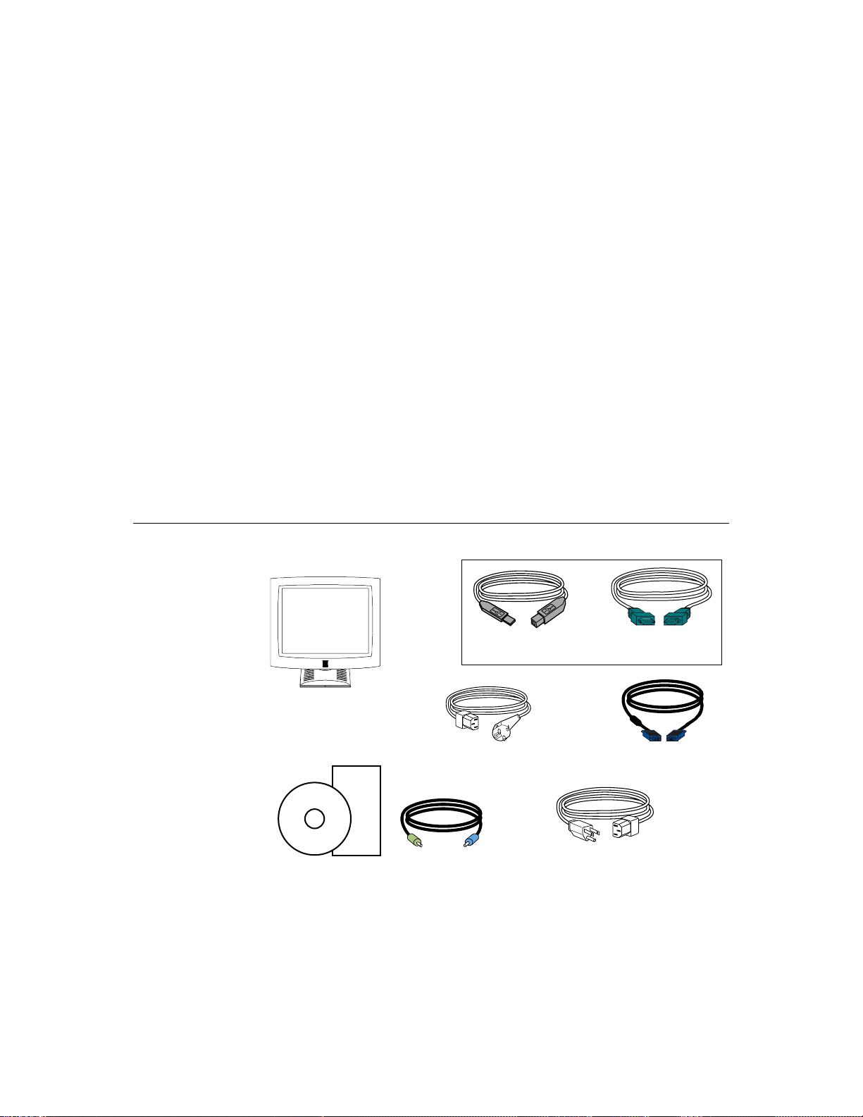
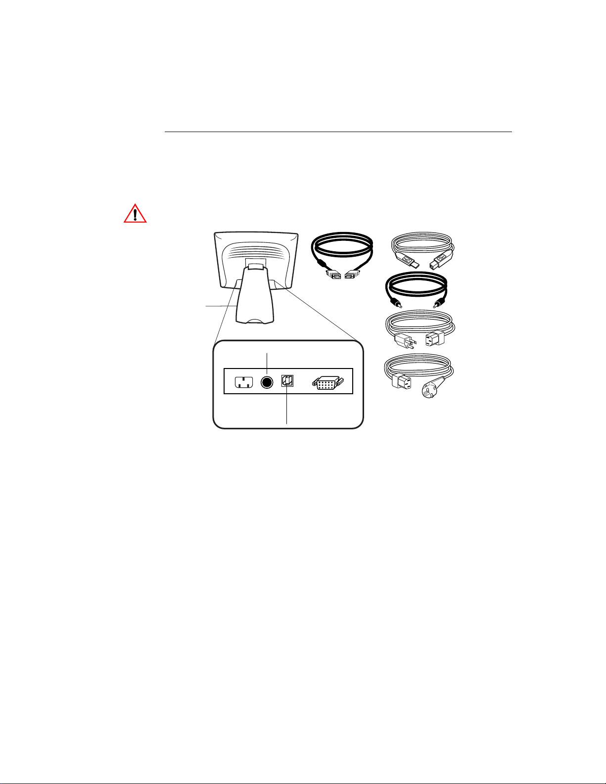
Unpac king Your Touc hm onitor
Check that the following 8 items are present and in good condition:
C HAPTER
2
S
ETUP
cable
LCD Display
European monitor power cable
Quick Install Guide
CD
Software
Speaker Cable
User Guide-on CD,
Quick Install Guide and software CD
OR
Serial touchscreenUSB touchscreen
cable
Video cable
Speaker cable
Monitor power cable
(US/Canada)
2-3
Page 7
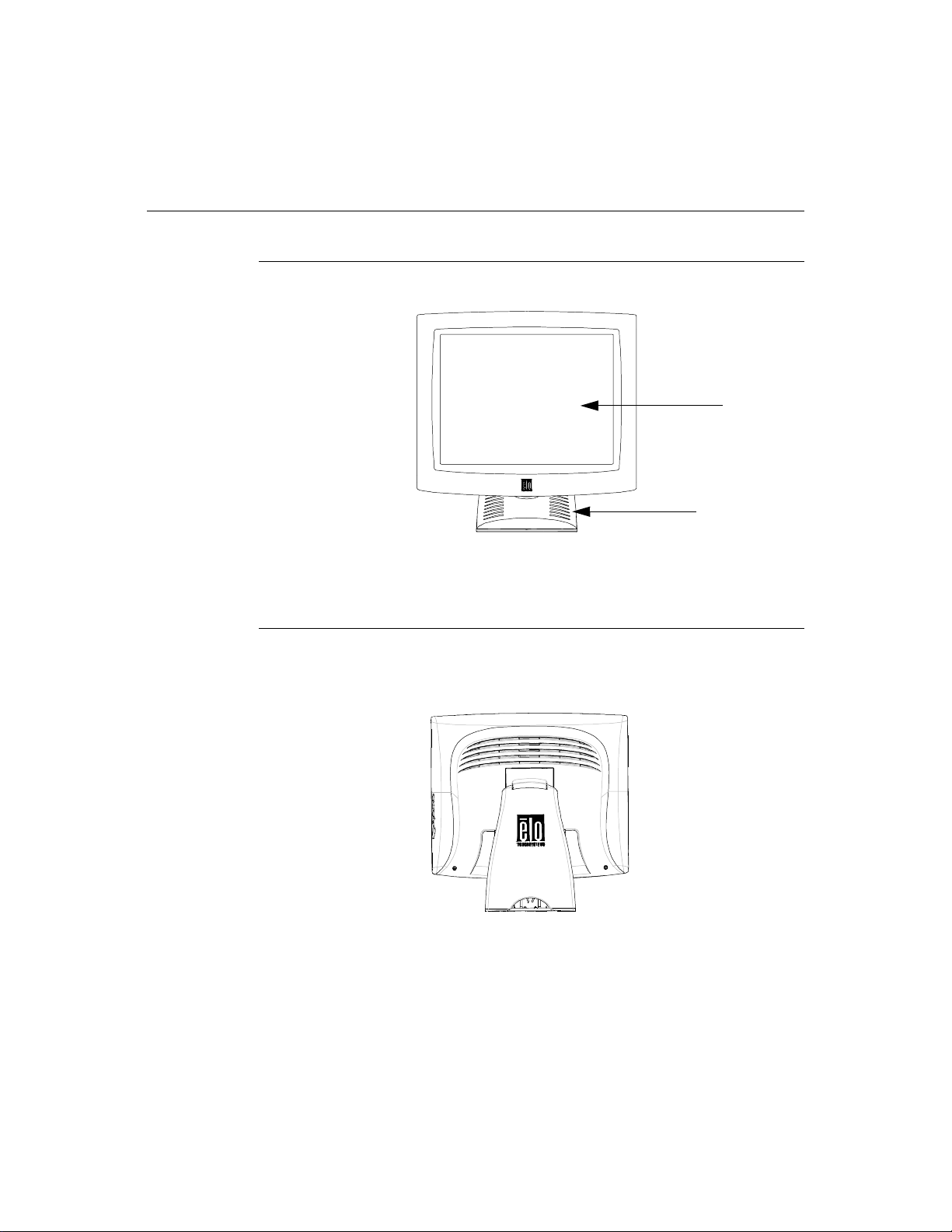
Prod uct O verview
Main Unit
Rear View
LCD Display
Stand
2-4 Elo Entuitive Touchmonitor User Guide
Page 8
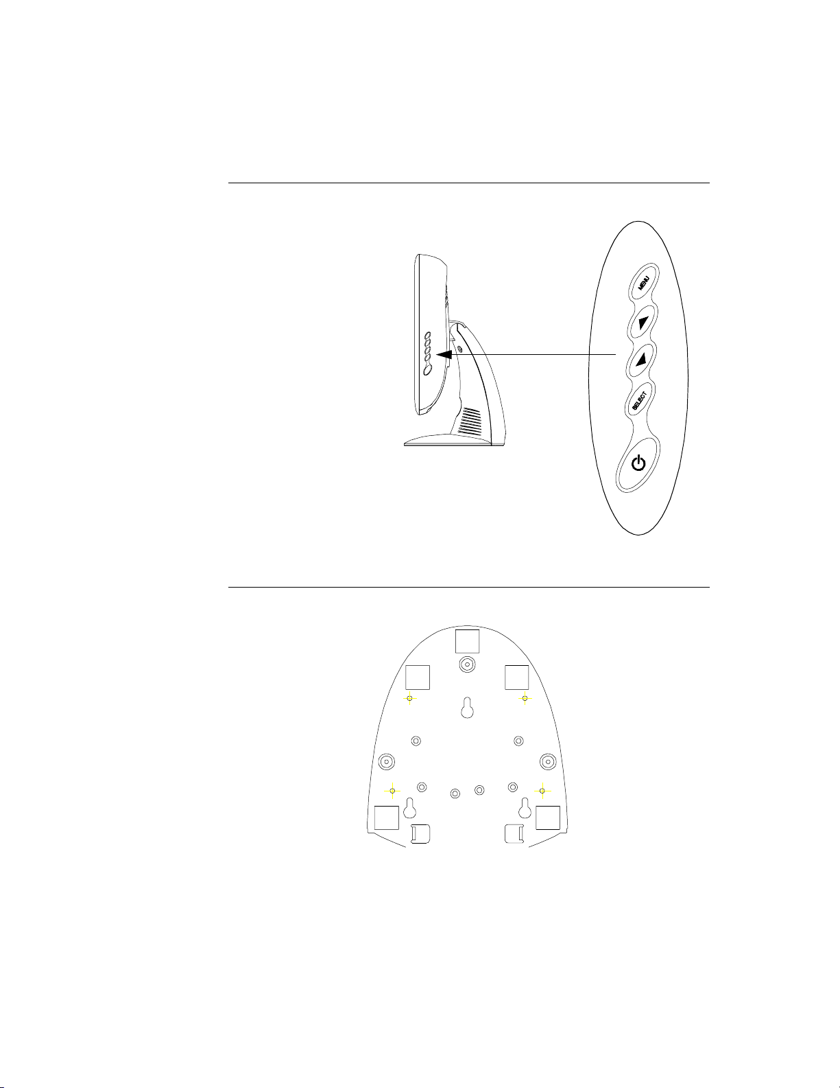
Side View
User Controls
Base Bottom View
2-5
Page 9
Touch Interface Connec tion
N
OTE
:
Your interface cables may hav e been pre-connected to y our monitor at the factory.
Your touchmonitor comes with one of the following touc hscreen connector
cables: Serial (RS-232) cable or USB cable. (For Windows 98, 2000, Me and
XP systems only.)
To set up this display, please refer to the following figures and procedures:
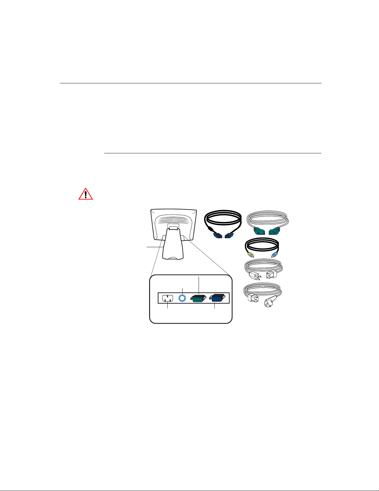
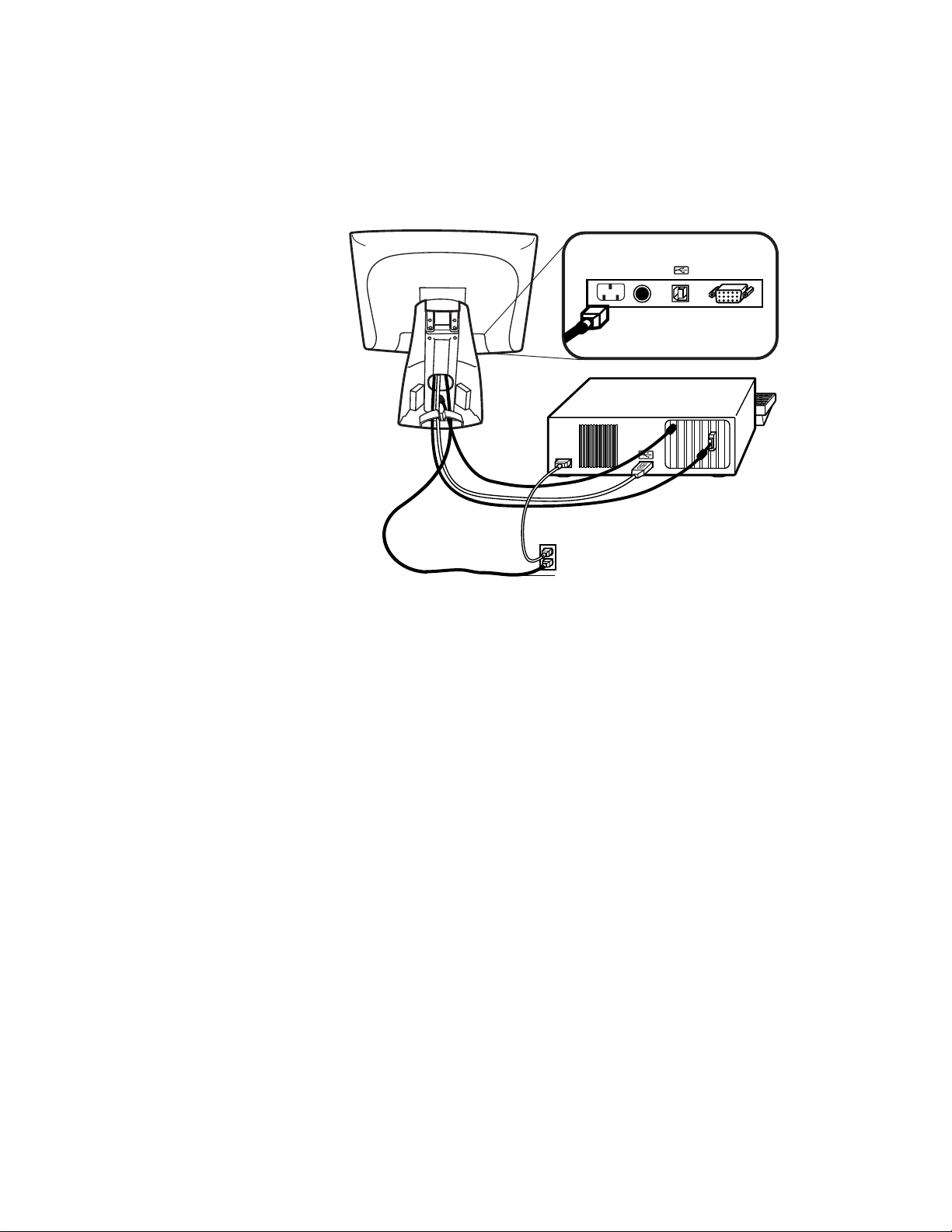
Serial Connection
The following illustrat ions guide you step by step in connecting your
touchmonitor using a serial cable connec tion.
CAU TION
Before connecting the cables to your touchmonitor and PC, be sure that the computer
and the touchmonitor are turned off.
Serial touchscreen
cable
Removable back cover
Speaker
port
Power
Connections on underside
Video cable
Female 9-pin serial
Touchscreen
connector
Female 15-pin
video
connector
Speaker
cable
Monitor
power cable
(US/Canada)
European monitor
power cable
2-6 Elo Entuitive Touchmonitor User Guide
Page 10

STEP 1-Removi ng the Back Co ver
Bottom cut-out
• The cables are routed thro ugh the back of the stand.
• To remove the back cover, place one hand at the top of the stand an d your
other hand on the bottom cut-out.
• Pull forward from the bottom cut- out an d twist the cover until it snaps off.
The cable ports are located on the underside of your touchmonitor.
2-7
Page 11
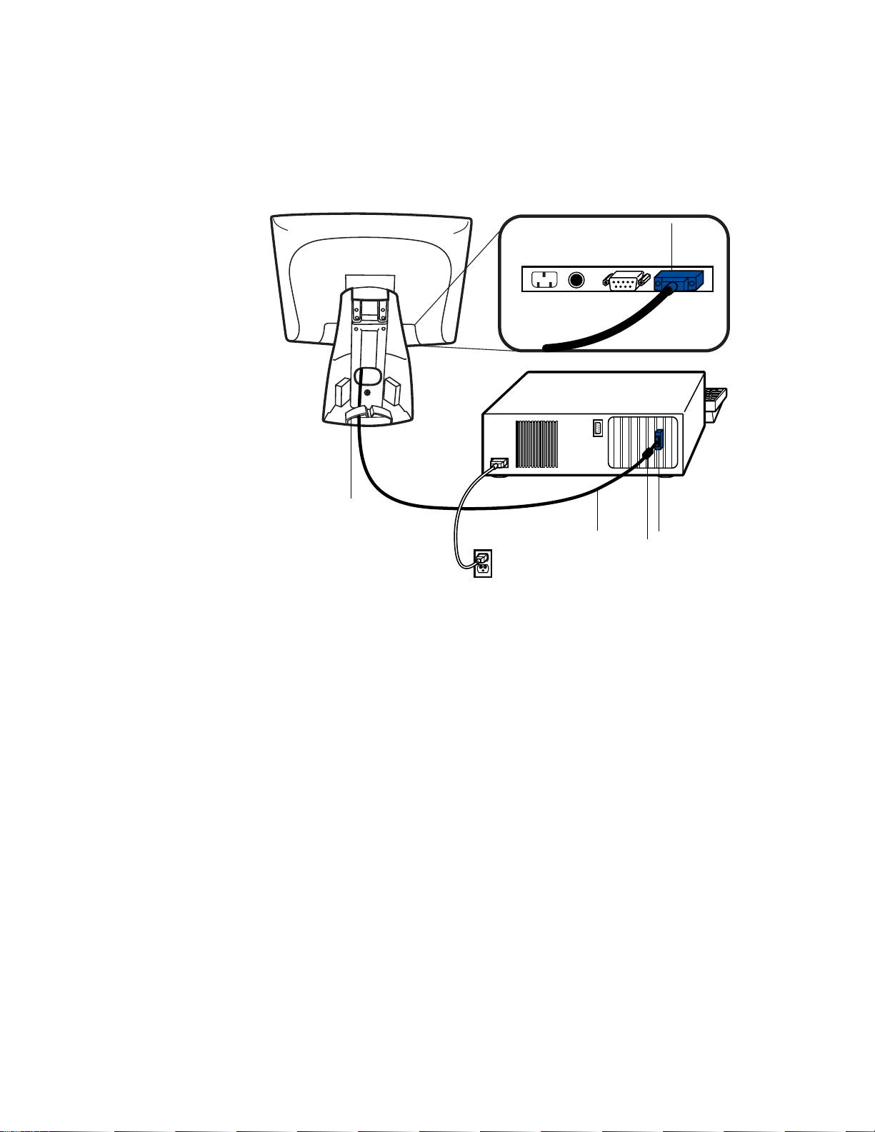
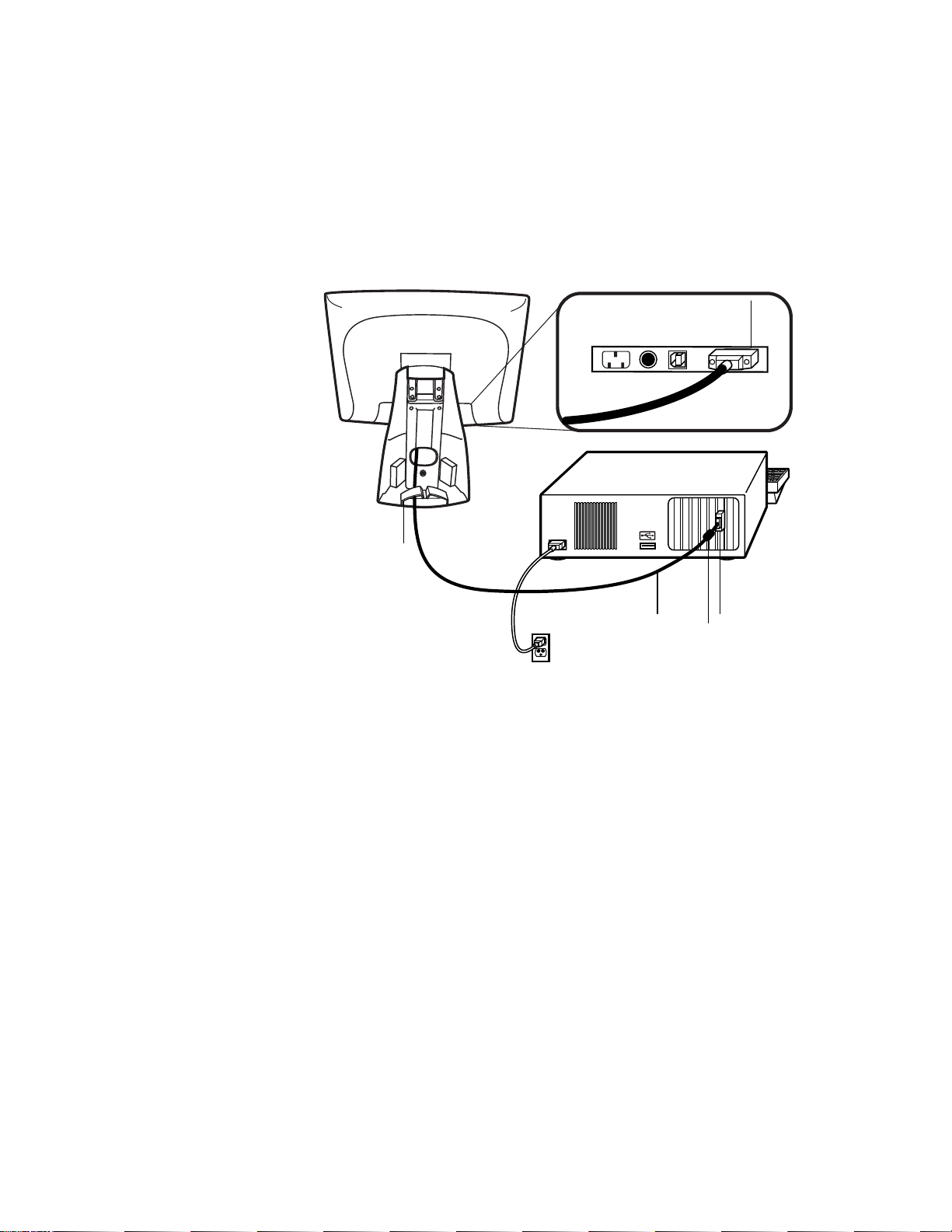
STEP 2-Connecting the Video Cable
Connections on underside
Female
video
connector
Cable management clip
Video
cable
Video
port
Ferrite bead
• Tilt the screen up and back to access the connection ports.
• Connect the 15-pin video cable (the ferrite bead end) to the video port on
your PC.
• Connect the other end of the video cable to the video connector on your
touchmonitor by routing the cable through the hole in the stand.
• Secure the cable to your touchmon itor and PC by turning the screws on the
connector clockwi se.
• Place the cable in the cable management clip.
2-8 Elo Entuitive Touchmonitor User Guide
Page 12
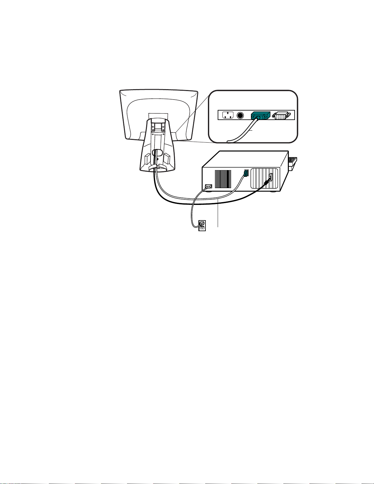
STEP 3-Connecting the S erial Touchscreen Cable
Connections on underside
Female 9-pin Serial
Touchscreen
connector
Serial
Touchscreen
cable
• Connect the female end of the serial (RS-232) cable to the serial port on the
back of your PC.
• Connect the male e nd of th e cable to t he s erial t ouchsc reen conne ctor on your
touchmonitor.
• Secure the cable to your touchmon itor and PC by turning the screws on the
connector.
• Route the cable through the cable management clip.
2-9
Page 13
N
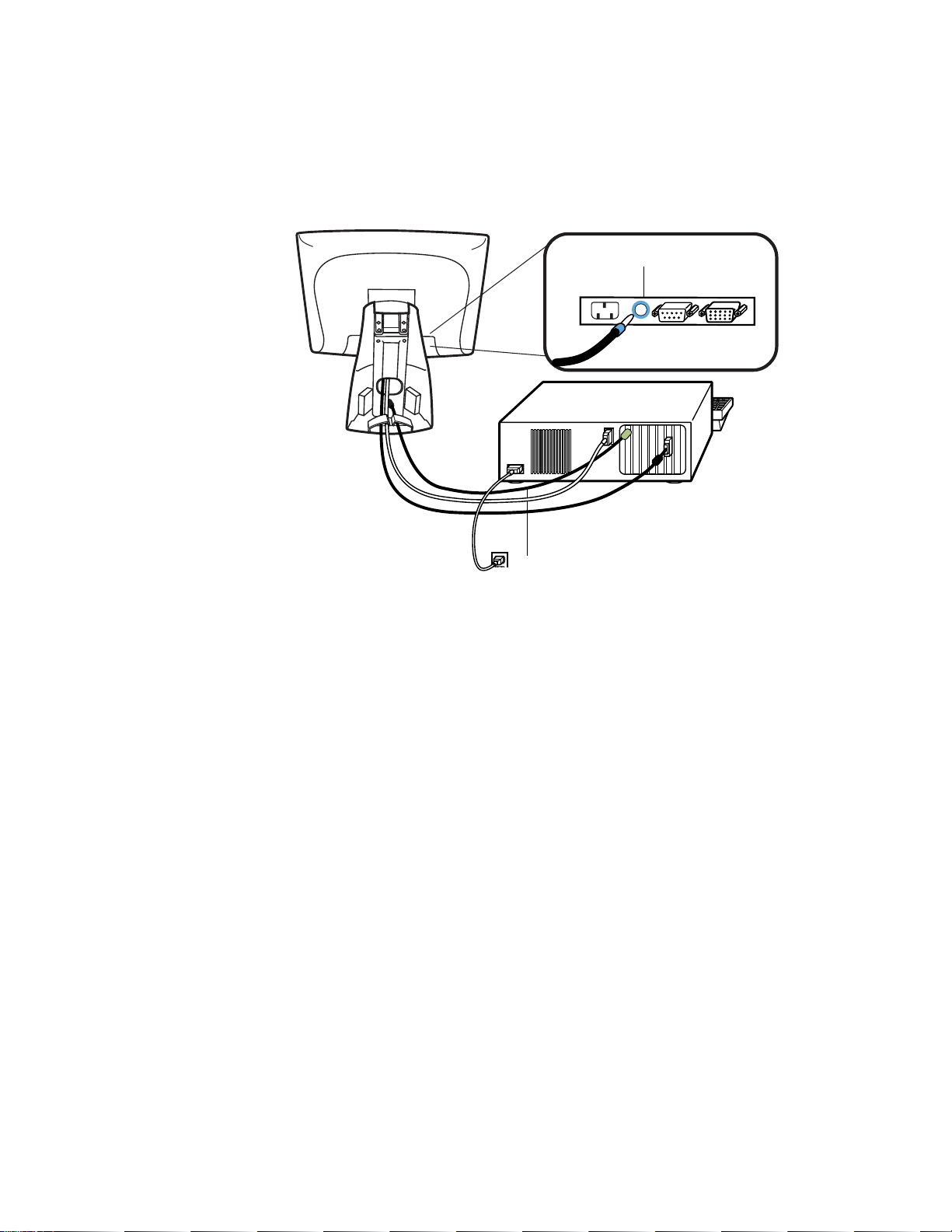
STEP 4-Connecting the S peaker Cab le
OTE
:
If you do not wish to connect the speaker cab le, go to step 5.
Speaker
cable
Connections on underside
Speaker port
• To use the built in speakers, you need to connect the speaker cable. Connect
the speaker cable to the speaker port inside the back of your touchmonitor.
• Connect the other end of the cable to the spe aker connector on your PC.
2-10 Elo Entuitive Touchmonitor User Guide
Page 14
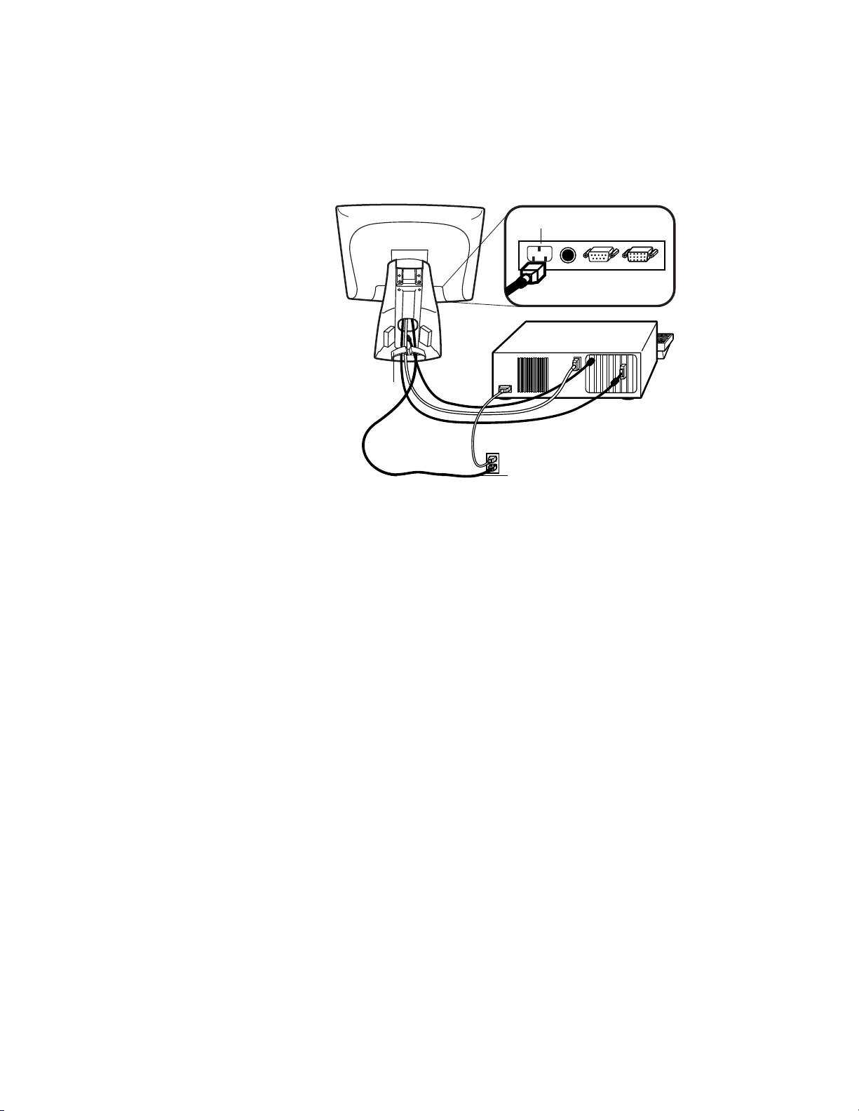
STEP 5-Connecting the Power Cable
Connections on underside
AC power cable port
Cable management clip
Power cable
Depending on where you live, you will use eit her the European or US/Canadian
power cable.
• Connect the female end of the power cable to the power port on the
touchmonitor.
N
• Route the cable through the cable management clip.
OTE
:
To protect your equipment against risk of damage from electrical surges in the power
line, plug the touchmonitor’s power cord int o a surge protector, and then connect the
surge protector to a grounded AC electrical outlet.
STEP 6-Replacing the Back Cover
When all the cables hav e been co nne ct ed:
• Replace the b ack sta nd co v er.
• Power on your PC then your touchmonitor. After a brief pause the picture
should appear.
2-11
Page 15
N
OTE
CAUT ION
USB Connection
:
A USB connection can only be used if your PC is running Windows 98, 2000, Me or XP.
The following illust rations guide you step by step in connecting your
touchmonitor using a USB cable connection.
Before connecting the cables to your touchmonitor and PC, be sure that the computer
and the touchmonitor are turned off.
USB touchscreen
cable
Removable
back cover
Speaker port
Connections on underside
USB port
Video cable
Female 15-pin
video
connector
Speaker cable
Monitor
power cable
(US/Canada)
European monitor
power cable
2-12 Elo Entuitive Touchmonitor User Guide
Page 16

STEP 1-Removi ng the Back Co ver
Bottom cut-out
• The cables are routed thro ugh the back of the stand.
• To remove the back cover, place one hand at the top of the stand an d your
other hand on the bottom cut-out.
• Pull forward from the bottom cut- out an d twist the cover until it snaps off.
The cable ports are located on the underside of your touchmonitor.
2-13
Page 17
STEP 2-Connecting the Video Cable
Connections on underside
Female 15-pin
Cable management clip
Video
cable
video
connector
Video
port
Ferrite bead
• Tilt the screen up and back to access the connection ports.
• Connect the 15-pin video cable (the ferrite bead end) to the video port on
your PC.
• Connect the other end of the video cable to the video connector on your
touchmonitor by routing the cable through the hole in the stand.
• Secure the cable to your touchmon itor and PC by turning the screws on the
connector clockwi se.
• Place the cable in the cable management clip.
2-14 Elo Entuitive Touchmonitor User Guide
Page 18
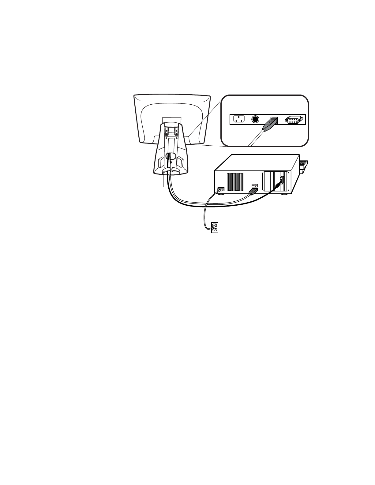
STEP 3-Connecting the U SB Touchscreen Cable
Connections on underside
USB
touchscreen
connector
Cable management clip
USB
touchscreen
cable
• Connect the USB t ouchscree n cabl e to the US B touch screen co nnector on the
touchmonitor.
• Connect the other end of the USB touchscreen cable to your PC.
• The touchscreen cabl e connector s should fit snugly into the connectors on
your touchmonitor and PC.
• Route the cable through the cable management clip.
2-15
Page 19
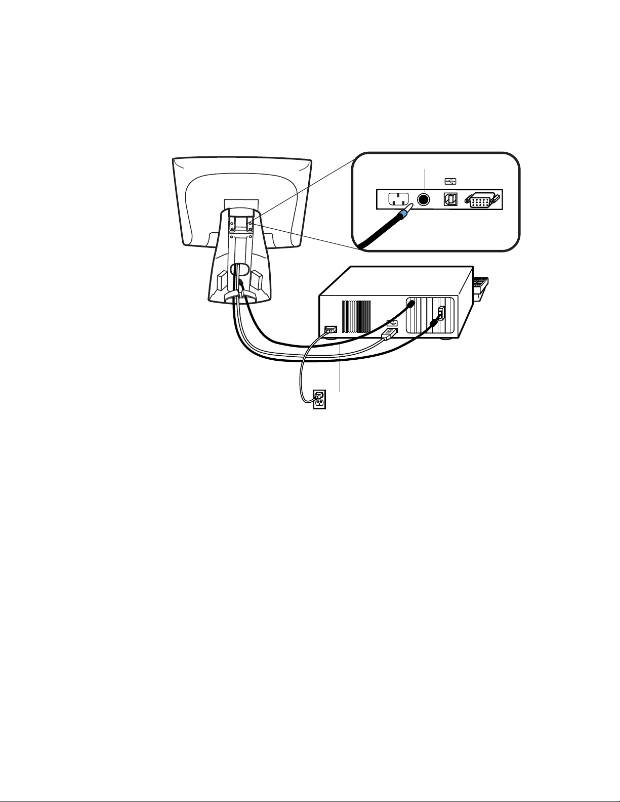
STEP 4-Connecting the S peaker Cab le
Speaker cable
Connections on underside
Speaker port
N
OTE
:
If you do not wish to connect the speaker cab le, go to step 5.
• To use the b uilt in s peake rs, you need to connect t he speaker c able. B oth ends
of the speaker cable are identical, so you can connect either end of the
speaker cable to the speaker port inside the stand of your touchmonitor.
• Connect the other end of the cable to the spe aker connector on your PC.
2-16 Elo Entuitive Touchmonitor User Guide
Page 20
STEP 5-Connecting the Power Cable
Connections on underside
Power cable
Depending on where you live, you will use eit her the European or US/Canadian
power cable.
N
• Connect the female end of the power cable into the power port on the
touchmonitor.
• Route the cable through the cable management clip.
OTE
:
To protect your equipment against risk of damage from electrical surges in the power
line, plug the touchmonitor’s power cord int o a surge protector, and then connect the
surge protector to a grounded AC electrical outlet.
STEP 6-Replacing the Back Cover
When all the cables hav e been co nne ct ed:
• Put the back stand cover on.
• Power on your PC then your touchmonitor. After a brief pause the picture
should appear.
2-17
Page 21
Optimizing the LCD Display
To ensure the LCD display works well with your compute r, configure the
display mode of your graphic card to make it less than or equal to 1024 x 768
resolution, and make sure the timi ng of the display mode is compatible with the
LCD display. Refer to Appendix A for more information about resolution.
Compatible video modes for your touchmonitor are listed in Appendix C.
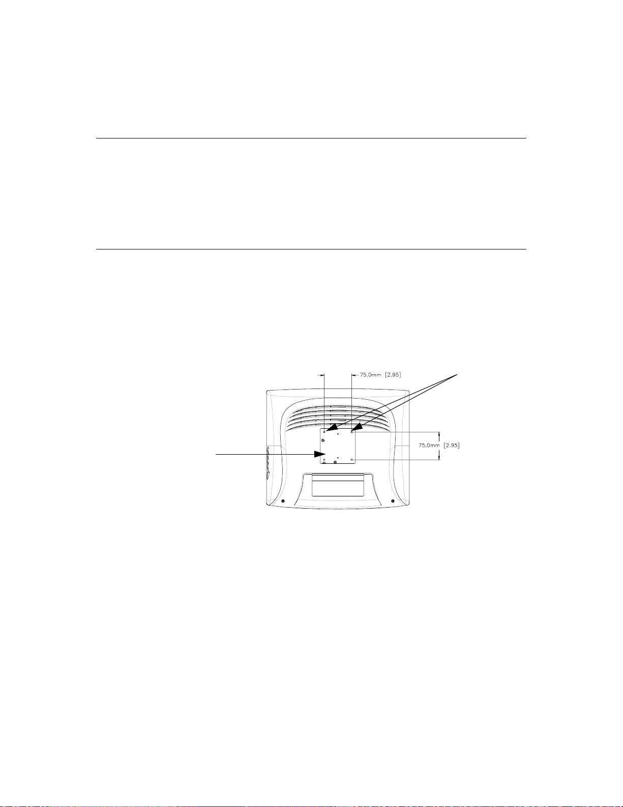
VESA M ou nt on Yo ur Touchm onitor
Your touchmonitor confo rms to the VESA Flat Panel Monitor Physical
Mounting Interface (FPMPMI™) Standard which defines a physical mounting
interface for flat panel monitors, and corresponding standards for flat panel
monitor mounting device s, suc h as wall and table arms. The VESA mounting
interface is loca ted on the back of your touchmonitor and is shipped
pre-connected to the base.
M4x0.7
threaded holes
VESA mounting
interface
N
OTE
:
The abov e drawing displays the VESA mounting interface after the removal of the
mounting cover and base.
2-18 Elo Entuitive Touchmonitor User Guide
Page 22

N
Accessing the VESA Mounting Interface
If you want to convert your desktop monitor to a wall mount or kiosk monitor,
follow the steps below to acces s the VESA mounting interface.
OTE
:
You will need a screwdriver f or the following steps.
1 Remove the back cover of the stand by pulling forward on the bottom
cut-out.
2 Carefully lay the monitor face down. At the top of the mounting screw cover
there are two slots. With a screwdriver, pry open the mounting screw cover.
The cover fit is tight so remove it carefully.
3 When you remove the mounting screw cover, you will see four screws.
Remove the screws to mount your monitor. Refer to the drawing on page 18.
The following companies provide VESA mounting devices compatible with
your touchmonitor:
Ergotron
800-888-8458
651-681-7600
www.ergotron.com
GCX
800-228-2555
707-773-1100
www.gcx.com
Mounting the B ase
You can also mount your touc hmonitor by using the keyholes in the base of the
stand. These keyholes provide easy slide on mounting. You can also bolt your
touchmonitor to a table top or other flat surface. Please refer to Appendix C for
location and dimension of the mounting holes.
Innovative Office Products
800-524-2744
610-253-9554
www.innov-office-prod.com
MRI
800-688-2414
www.mediarecovery.com
2-19
Page 23

Installing the D river Soft ware
Elo TouchSystems provides driver software that allows your touchmonitor to
work with your computer. Drivers a re located on the enc losed CD-ROM for the
following operat ing systems:
• Windows XP
• Windows 2000
• Windows Me
• Windows 98
• Windows 95
• Windows NT 4.0
Additional driver s and driver information fo r other operating systems (i ncluding
MS DOS, Windows 3.x, OS/2, Macintosh and Linux) are available on the Elo
TouchSystems web site at www.elotouch.com.
Your Elo touchmonitor is plug-a nd-play compliant. Information on the video
capabilitie s of your touchmonitor is sent to your video display adapte r when
Windows starts. If Windows detects your touchmonitor, follow the instr uctions
on the screen to install a generic plug-and-play monitor.
Refer to the appropriat e following section for driver installation instructions.
2-20 Elo Entuitive Touchmonitor User Guide
Page 24

N
Installing the Serial T o uch Driver for Windows XP,
Windows 20001, Me, 95/98 and NT 4.0
OTE
:
For Windows 2000 and NT 4.0 you must have administrator access rights to install the
driver.
1 Insert the Elo CD-ROM in your computer’s CD-ROM drive.
If the AutoStart feature for your CD-ROM drive is active, the system
automatically de tects the CD and starts the setup program.
2 Follow the directions on the screen to complete the driver setup for your
version of Windows.
If the AutoStart featu re is no t acti ve:
1 Click Start > Run.
2 Click the Browse button to locate the EloCd.exe program on the CD-ROM.
3 Click Open, then OK to run EloCd.exe.
4 Follow the directions on the screen to complete the driver setup for your
version of Windows.
1.To install Windows 2000 and Windows XP, you must use the "update driver"
method; you will not find a setup.exe fil e within the download.
2-21
Page 25

Inst a lling the Serial Touch Driver for M S-DOS and Windows 3. 1
You must have a DOS mouse driver (MOUSE.COM) installed for your mouse
if you wish to continue using your mouse along with your touchmonitor in
DOS.
To install Windows 3.x and MS-DOS from Windows 95/98, follow the
dire c t io ns be lo w:
1 Insert the Elo CD-ROM in your computer’s CD-ROM drive.
2 From DOS, type d:\EloDos_W31 to change to the correct directory on the
CD-ROM (your CD-ROM drive may be mapped to a different drive letter).
3 Type install and press Enter to start the installation.
4 Align the touchscree n.
You must have already completed Steps 1 and 2 before proceeding. Refer to
Chapter 2 of the Elo DOS and Windows Driver Guide as necessary for
additional ins tallation information.
To run the INSTALL program:
1 Type INSTALL at the DOS prompt in the directory containing the driver
inst a l l f i l e s .
2 INSTALL asks you to select the softwar e to install. Then choose
d:\EloDos_W31 from the displ ayed list.
3 INSTALL also asks you for the paths to use during ins tallation, or you may
use its defaults. INSTALL creates directories as necessary, and warns you if
they exist.
If you are updating your softwar e, you may wish to specify the paths conta ining
the earlier versi ons, and overwrite the obsolete files. All executable programs
are upward comp a tib le. Fo r a list of differences from each prev iou s ve rsion of
the drivers, be sure to select "Differences from Previous Versions" during the
installation process.
INSTALL updates your AUTOEXEC.BAT file with the drivers you select.
INSTALL makes a copy of your original AUTOEXEC.BAT file, cal led
AUTOEXEC.OLD. If you already have Elo driver commands in your
AUTOEXEC.BAT file, they will be commented out.
When INSTALL is finished, it leaves a file called GO.BAT in the subdirectory
you specified. GO loads the touchscreen driver, runs the calibration program
ELOCALIB, and gives you some final instructions.
If you are using Windows 3.1, you will also calibrate the touchscreen within
Windows 3.1 with the Touchscreen Control Panel.
2-22 Elo Entuitive Touchmonitor User Guide
Page 26

N
To install Windows 2000 and Windows XP, you must use the "update
driver" method; you will not find a setup.exe file within the download
Installing the USB Touch Driver
Installing the USB Touch Driver for Windows XP, Windows 2000,
Me and 98
1 Insert the Elo CD-ROM in your computer’s CD-ROM drive.
If Windows 98 or Windows 2000 starts the Add New Hardware Wizard:
2 Choose Next. Select “Search for the best driver for your device
(Recommended)” and choose Next.
3 When a list of search locations is displayed, place a checkmark on “Specify a
location” and use Browse to select the \EloUSB directory on the Elo
CD-ROM.
4 Choose Next. Once the Elo TouchSystems USB touchscreen driver has been
detected, choose Next again.
5 You will see several files being copied. Insert your Windows 98 CD if
prompted. Choose Finish.
If Windows 98 or Windows 2000 does not start the Add New Hardware Wizard:
OTE
:
For Windows 2000 you must have administrator access rights to install the driver.
1 Insert the Elo CD-ROM in your computer’s CD-ROM drive.
If the AutoStart feature for your CD-ROM drive is active, the system
automatically detects the CD and starts the setup program.
2 Follow the directions on the screen to complete the driver setup for your
version of Windows.
If the AutoStart feature is not active:
1 Click Start > Run.
2 Click the Browse button to locate the EloCd.exe program on the CD-ROM.
3 Click Open, then OK to run EloCd.exe.
4 Follow the directions on the screen to complete the driver setup for your
version of Windows.
2-23
Page 27

2-24 Elo Entuitive Touchmonitor User Guide
Page 28

About T ouchmonitor Adjustments
Your touchmonitor will unlikely require adjustment. Variations in video output
and application may requi re adjustments to your touchmonitor to optimize the
quality of the displa y.
For best performance, your touchmonitor should be operating in native
resolution, that is 1024 x 768 at 60-75 Hz. Use the Display control panel in
Windows to choose 1024 x 768 resolution.
C HAPTER
3
C
HAPTER
3
O
PERATION
Operating in other resolutions will degrade video performance. For further
information, please refer to Appendix A.
All adjustments you make to the controls are automatically memorized. This
feature saves you from having to rese t your choices every time you unplug or
power your touchmonitor off and on. If there is a power failure your
touchmonitor settings will not default to the factory specifications.
Using the On- Screen Displa y (OSD) M enus
All adjustments are made by using the on-screen display (OSD) menus. All
menu items can be selected by using the buttons on the side bezel.
N
OTE
:
OSD menu default is enabled.
3-25
Page 29
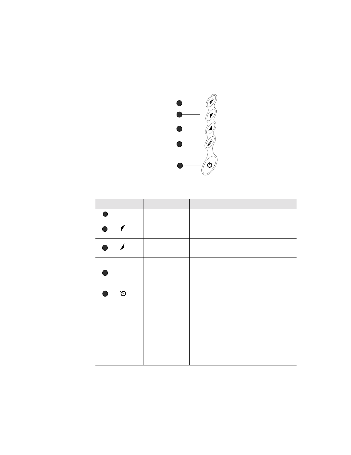
Side Be zel Butt ons
MENU
1
2
3
SELECT
4
1
2
3
4
5
Contro l Function
Menu Display on ex it the OSD menus.
Contrast/
Up/Toggle
Volume/Down
Toggle
Enter Select item
1. Shortcut to Contrast adjustment
2. Increase value of adjustment items
3. With menu on toggles OSD options
1. Shortcut to Volume adjustment
2. Decrease value of the adjustment items
3. With menu on toggles OSD options
1. Shortcut to Auto Adjust
2. Select- To select the adjustment items from the
OSD menus.
3. Auto- To act ivate the “Auto Adjustment”
function to obta in an optimum image.
5
3-26 Elo Entuitive Touchmonitor User Guide
Power Switch Switches the power on/off to your touchmonitor.
Enable/ D isable 1. Press th e U p and Down buttons at the same
time to ena ble /d is abl e the MU TE f unc ti ons . OS D
menu default is enabled
2. Press the Me nu and Up buttons at the same
time and hold for two seconds to enable/disable
the OSD functions. OSD menu default is
enabled.
3. Press the Me nu and Down buttons at the same
time and hold for two seconds to enable/disable
the power loc k function. OSD menu default is
enabled.
Page 30
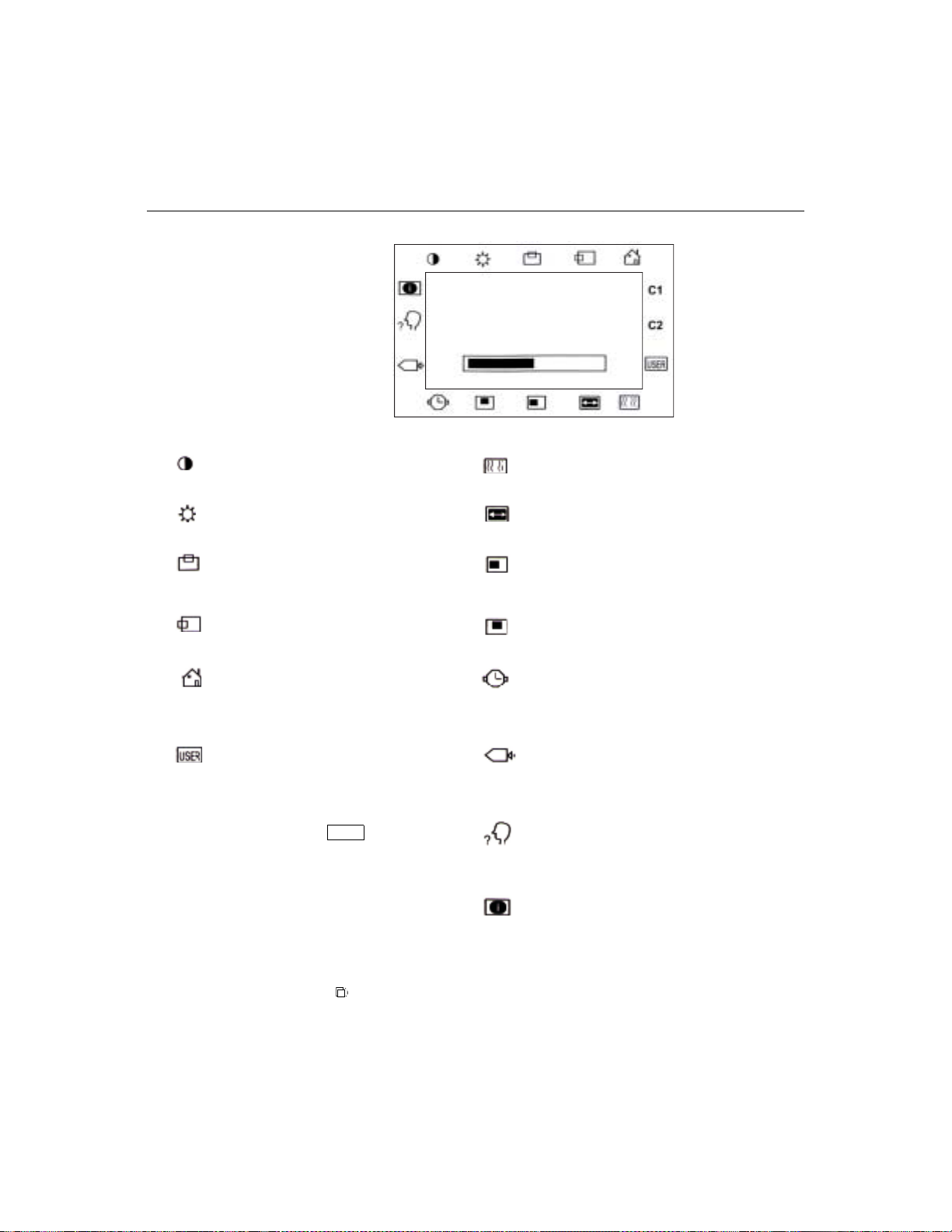
OSD M enu F unction
CONTRAST
50
Contrast
Controls the picture contrast
Brightness
Controls the picture brightness
V-Position
Controls the vertical position
H-Position
Controls the horizontal position
Recall De faults
Recalls f actory settings of the image
parameters
C1/C2/USER (Color)
Using these icons, you can select one of
the preset color temperatures (9300°K or
6500°K). Confirm your choice by
pres si ng the SELECT button. If you
want to change the color temperatu res
individually, select USER and confirm by
pressing the OSD button SELECT. Now
you can use the OSD dial to toggle
between the settings R, G and B (red,
green and bl ue foregroun d). T o change a
setting, first press the SELECT button,
then ch oo s e the desired value w ith the
OSD dial. To confirm the setting, press
the SELECT button again.
If you don’t need to adjust an y further
settings, choose the
icon to return to the OSD main menu.
Phase
Controls the vertical fine adjustment
Clock
Controls the horizontal fine adjustment
OSD H-Position
Adjusts the horizontal position of the OSD
menu
OSD V-Position
Adjust th e vertical position of the OSD men u
OSD Time
Determines how long (in seconds) the OSD
menu waits befor e cl osing au to m a tic a lly after
no action has been performed.
Auto Adjus t
Autom at ic a lly selects th e o ptional set tings for
image parameters (brightness, contrast, image
position, phase, etc.)
OSD Language
Selection of the OSD menu langu age: English,
French, Ge rm an, Spanish, Japanese.
Image Inform ation
Display s the current graphics mode.
3-27
Page 31

3-28 Elo Entuitive Touchmonitor User Guide
Page 32

If you are experiencing trouble with your touchmonitor, refer to the following
table. If the problem persists, please contact your local dealer or our service
center.
Solutions to Common Problems
Problem Suggestion(s)
C HAPTER
4
C
HAPTER
4
T
ROUBLESHOOTING
No image ap pears on screen . Check that al l the I/O and power connectors are properly
connected as described in Chapter 2.
Make sure the pins of the connectors are not cr ooked or
broken.
Test power su pply by trying different cable s, a different
wall outlet or plug another appliance into the outlet.
Make certa in the vi deo cab le is prope rl y conne ct ed a nd tha t
it is not damaged. Check for bent pins on the cable
connectors.
Ensure that your computer and video card are properly
configured. (Consult video card documentation.)
“Out of Range ” display Check to see if the resolution of your compute r is higher
than that of the LC D display.
Reconfigure the resolution of your computer to make it less
than or equal to 1024 x 768. See Appendix A for more
info rmation on res olution .
4-29
Page 33

Image has vertical flickering line bars. Use “PHASE” to make an adjustment .
Check and reco nfigure the display mode of the vertical
refresh ra te of y our gr aph ic car d t o mak e it co mpat ib le with
the LCD display.
Image is uns table and flicke ring Use “CLOC K” to m ake an adjustme nt.
Image is scrolling Make sure the VGA signal cable (or adapter) is well
connected.
Check and reco nfigure the display mode of the vertical
refresh ra te of y our gr aph ic car d t o mak e it co mpat ib le with
the LCD display.
Touch doesn’t work Make sure cable is securely attached at both ends.
4-30 Elo Entuitive Touchmonitor User Guide
Page 34

A PPENDIX
A
C
HAPTER
4
N
ATIVE
The native resolution of a monitor is the resolution level at which the LCD
panel is designed to perfor m best. For the Elo LCD touchmonitor, the native
resolution is 1024 x 768 for the XGA-15 inch siz e. In almost all cases, screen
images look best when viewed at their native resolution. You can lower the
resolution setting of a monitor but not increase it.
Input Video 15" LCD
640x480 (VGA) Transforms input format to 1024x768
800x600 (SVGA) Transforms input format to 1024x768
1024x768 (XGA) Displays in Native Resolution
R
ESOLUTION
The native resolution of an LCD is the actual number of pixels horizontally in
the LCD by the number of pixels vertical ly in the LCD. LCD resol ution is
usually represented by the following symbols:
VGA
SVGA
XGA
SXGA
UXGA
640x480
800x600
1024x768
1280x1024
1600x1200
A-31
Page 35

As an example, a SVGA resolution LCD panel has 800 pixels horizontally by
600 pixels vertically. Input video is also represented by the same terms. XGA
input video has a format of 1024 pixels hor iz ontally by 768 pixels vertically.
When the input pixels containe d in the video input format match the native
resolution of the pa nel, there i s a one to one corre spondence of mapping of input
video pixels to LCD pixels. As an example, the pixel in column 45 and row 26
of the input video is in column 45 and row 26 of the LCD. For the case when
the input vide o is a t a lowe r res oluti on than t he nat ive res oluti on of th e LCD, the
direct corresponde nce between the video pixels and the LCD pixels is lost. The
LCD controller c an compu te the correspon dence be tween video pi xels a nd LCD
pixels using algorithms contained on its controller. The accur acy of the
algorithms determines the fidelity of conversion of video pixels to LCD pixels.
Poor fideli ty conversion can result in artifacts in the LCD displayed image such
as varying width charact ers.
A-32 Elo Entuitive Touchmonitor User Guide
Page 36

A PPENDIX
B
C
HAPTER
4
T
OUCHMONITOR
This manual contains inf ormation that is important for the proper setup and
maintenance of your touc hmonitor. Befor e setti ng u p and poweri ng on your new
touchmonitor, read thr ough this manual, especia lly Chapter 2 (Insta llati on), and
Chapter 3 (Ope rati o n).
1 To reduce the risk of electric shock, follow all safety notices and never open
the touchmonitor case.
2 Turn off the product before cleaning
S
AFE TY
3 Your new touchmonitor is equipped with a 3-wire, grounding power cord.
The power cord plug will onl y fit into a grounde d outlet. Do not a ttempt to fit
the plug into an outlet that has not been confi gured for this purpose. Do not
use a damaged power cord. Use only the power cord that comes with your
Elo TouchSystems Touchmonitor. Use of an unauthorized power cord may
invalidate your warranty.
4 The slots located on the sides and top of the touchmo nitor case are for
ventilatio n. Do not bloc k or insert anything inside the ventilati on slots.
5 It is important that your touchmonitor remains dry. Do not pour liquid int o or
onto your touchmonitor . If your touchmo nitor becomes wet do not attempt to
repair it yourself.
B-33
Page 37

Care an d Handling of Your T o uchm onitor
The following tips will help keep your Elo Entuitive touchmonitor functioning
at the optimal level.
• To avoid risk of electric shock, do not disassemble the brick supply or
display unit cabine t. The unit is not user serviceable. Remember to unplug
the display unit from the power outlet before cleaning.
• Do not use alcohol (methyl, ethyl or isopropyl) or any strong dissolvent. Do
not use thinner or benzene, abra sive cleaners or compressed air.
• To clean the display unit cabinet , use a cloth lightly dampened with a mild
detergent.
• Avoid getting liquids inside your touchmonitor. If liquid does get inside,
have a qualified servi ce te chnician check it before you power it on again.
• Do not wipe the screen with a cloth or sponge that could scratch the surface.
• To clean the touchscreen, use window or glass cleaner. Put the cleaner on the
rag and wipe the touchscreen . Never apply the cleaner directly on the
touchscreen
B-34 Elo Entuitive Touchmonitor User Guide
Page 38

A PPENDIX
C
C
HAPTER
4
T
ECHNICAL
Compatib le Video Modes
Your Elo Entuitive touchmon itor is compatible with the following standard
video modes:
Mode Resolution H. Frequency (kHz) V. Frequency (Hz)
IBM & VESA VGA 640 x 350 31.47 70.09
IBM & VESA VGA 640 x 400 31.47 70.09
IBM & VESA VGA 720 x 400 31.47 70.09
IBM & VESA VGA 640 x 480 31.47 59.94
IBM & VESA VGA 640 x 480 37.86 72.81
IBM & VESA VGA 640 x 480 37.50 75.00
VESA SVGA 800 x 600 35.16 56.25
VESA SVGA 800 x 600 37.88 60.32
VESA SVGA 800 x 600 48.08 72.19
VESA SVGA 800 x 600 46.88 75.00
VESA XGA 1024 x 768 48.36 60.00
VESA XGA 1024 x 768 56.48 70.07
VESA XGA 1024 x 768 60.02 75.03
Apple Macintosh LC 13” 640 x 480 34.97 66.61
Apple Macintosh II 13” 640 x 480 35.00 66.67
Apple Macintosh 16” 832 x 624 49.73 74.55
Apple Macintosh 19” 1024 x 768 60.24 75.02
NEC FC-98 series 640 x 400 24.83 56.42
NEC FC-98 series 640 x 400 31.47 70.01
NEC FC-98 series 640 x 480 31.47 59.94
S
PECIFICATIONS
C-35
Page 39

Touchm onitor Sp ecifications
Table C.1
15" LCD Touchmonitor (ET1 5-XXWA-1) Specifications
Display Type
Size
Pixel Format
Touchscreen
Colors
Display
Active matrix, thin film transistor
(TFT) , liquid cr ystal display
15-inch diagonal
304.1 x 228.1 m m useful screen
area
1024 x 768
0.125-inch IntelliTouch and
AccuTouch, anti-glare
Intelli Touch or AccuTouch
16 million with dithering
IntelliTouch: 270 cd/m² typical AccuTouch: 250 cd/m² typical
Brightness
Back-light Lamp
Life
Viewing Ang le
Contrast Ratio
Display R esponse
25,000 hou rs at 50% brightness
typical
Horizontal
Vertical
450:1 typical
13 ms (tr) /2 7 ms (tf)
Time
Environmental
Mechanical
Electrical
Speak ers
Agencies
Operating Temp
Storage Temp
Humidity
Weight
Size
Input Video
Input Power
Power Dissipation
8 ohms, 1 watt per speaker
Safety & EMC UL, cUL and TUV-GS, FCC-B,
±65 or 12 0 de gree s total
±60- 45 or 105 deg re es tota l
0°C to 40°C
-25°C to +60°C
80% non-condensing AT
95% IT
17 lbs. maximum approx. weight
for IntelliTouc h an d A cc u T ouch
See drawings on next page.
VGA/SVGA/XGA analog video
100-240 VAC, 50/60 Hz.
Universal
CE, C-Tick and VCCI
C-36 Elo Entuitive Touchmonitor User Guide
Page 40

Table C.2
Mechanical
Positional Accuracy
Touchpoint Densit y
Touch Activation
Force
Surface Durability
Expected Life
Performance
Sealin g
Optical
Light Transmission
(per ASTM D1003)
Visual Resolution
Gloss (per ASTM
D2457 using a 60degree gloss meter)
IntelliTouch Touchmonitor Specifications
Standard deviation of error is less than 0.080 in. (2.03 mm).
Equate s to les s th an ± 1%.
More than 100,000 touchpoints/in2 (15,500 touchpoints/cm2).
Typically less than 3 ounces (85 grams).
Surfac e durability is that of glass, Mohs’ hardness rating of 7.
No know n we ar -o ut mech an ism, as th ere are no layers, coating s,
or moving pa rts. Intelli T ouch technology has been opera tionally
tested to more th an 5 0 millio n to uches in o n e location w ithout
failure, using a stylus similar to a finger.
Unit is sealed to protect against splashed liquids, dirt, and dust.
90%
All measurem ents made using U SA F 1951 Resolution Chart,
under 30X magnification, with test unit located approximately
1.5 in (38 mm) from surface of resolution chart.
Clear surface: Excellent, with no noticeable degradation.
Antiglare surface: 6:1 minimum.
Antiglare surface: Curved: 60 ± 20 gloss units or 75 ± 15 gloss
units.
C-37
Page 41

Environmental
Chemical Resistance
Electrostatic
Protection (per EN 61
000-4-2, 1995)
The acti ve area of the touchscreen is resistan t to all chemicals
that do no t affect glass, such as:
Acetone
Toluene
Methyl et hyl ketone
Isopropyl alcohol
Methyl alcohol
Ethyl ac etate
Ammo ni a-bas ed gl ass clea n er s
Gasoline
Kerosene
Vinegar
Meets Level 4 (15 kV air/8 kV contact discharges).
C-38 Elo Entuitive Touchmonitor User Guide
Page 42

Table C.3
AccuTouch Touchmonitor Specifications
Mechanical
Construction
Positional Accuracy
Touchpoin t Dens it y
Touch Activatio n Force
Surface Durability
Expected Life
Performance
Optical
Light Transmis s ion
(per ASTM D1003)
Visual Resolution
Haze (per ASTM D1003)
Gloss (per ASTM D2457)
Top: Pol ye s te r w ith ou ts id e har d -surfac e co a tin g wi th cle ar or
antiglare finish.
Inside: Transparent conductive coating.
Bottom: G lass substrate with uniform resistive coating. Top and
bottom la yers separated by Elo-patented separator dots.
Standard deviation of error is less than 0.080 in. (2.03 mm). This
equates to less than ±1%.
More than 100,000 touchpoints/in² (15,500 touchpoints/cm²).
Typically less than 4 ounces (113 grams).
Meets Taber Abrasion Test (ASTM D1044), CS-10F wheel, 500 g.
Meets pencil hardness 3H.
AccuTouch technology has been operationally tested to greater than
35 million touches in one location without failure, using a stylus
similar to a finger.
Typically 75% at 550-nm wavelength (visible light spectrum).
All measurements made using USAF 1951 Resolution Chart, under
30 X magnification, with test unit located approximately 1.5 in. (38
mm) from surface of resolution chart.
Antiglare surface: 6:1 minimum.
Antiglare surface: Less than 15%.
Antiglare surface: 90 ± 20 gloss units tested on a hard-coated front
surface.
C-39
Page 43

15" LCD Touc hmon itor (ET 15-XXWA-1) Dim ensions
C-40 Elo Entuitive Touchmonitor User Guide
Page 44

See Detail A
Detail A
C-41
Page 45

C-42 Elo Entuitive Touchmonitor User Guide
Page 46

C
HAPTER
4
R
EGULATORY INFORMATION
I. Electrical Safety Inform ation:
A) Compliance is required with respect to the voltage, frequency, and current
requirements indicated on the manufacturer’s label. Connection to a different
power source than those specified herein will likely result in improper operation,
damage to the equipment or pose a fire hazard if the limitations are not followed.
B) There are no operator serv iceable parts inside this equipment. The re are haza rdous vol tages genera ted by this equipment which constitute a safety hazard. Service
should be provided only by a qualifi ed service technician.
C) This equipment is provided with a detachable po w er cord which has an integral
safety ground wire intended for connection to a grounded safety outlet.
1) Do not substi tute the cord with othe r than the provide d approved typ e.
Under no circumstances use an adapter plug to connect to a 2-wire outlet as
this will defeat the continuity of the grounding wire.
2) The equipment requires the use of the ground wire as a part of the safety
certification, modification or misuse can provide a shock hazard that can
result in serious injury or death.
3) Contact a qualified electrician or the manufacturer if there are questions
about the installation prior to connecting the equ ipment to mains power.
II. Emissions and Immunity Information
A) Notice to Users in the United States: This equipment has been tested and found
to comply with the limits for a Class B digital device, pursuant to Part 15 of FCC
Rules. These limits are designed to provide reasonable protection against harmful
interference in a residential installation. This equipment generates, uses, and can
radiate radio frequency energy, and if not installed and used in accordance with the
instructions, ma y cause harmful interference to radio communications.
B) Noti ce to Users in Canada: This equipment complie s with the C lass B lim its for
radio noise emissions from digital apparatus as established by the Radio Interference Regulations of Industrie Canada.
C) Notic e to U se rs in th e E ur o pe an Unio n: Us e only the prov id ed power cords and
interconnecting cabling provided with the equipment. Substitution of provided
cords and cabling may compromise electrical safety or CE Mark Certification for
emission s or immunity as required by the following standards:
43
Page 47

This Inform ation T echnology Equipment (ITE) is required to have a CE Mark
on the manufacturer’s label which means that the equipment has been tested
to the following Direc tives an d Standards:
This equipment has been tested to the requirements for the CE Mark as
required by EMC Directive 89/336/EEC indicated in European Standard EN
55 022 Class B and the Low Voltage Directive 73/23/EEC as indicated in
European Standard EN 60 950.
D) General Information to all Users: This equipment generates, uses and can radiate radio frequency energy. If not installed and used according to this manual the
equipment may cause interference with radio and television communications.
There is, however, no guarantee that interference will not occur in any particular
instal lation due to site-specific factors.
1) In order to meet emission and immunity requirements, the user must
observe the following:
a) Use only the provided I/O cables to connect this digital device with
any computer.
b) To ensure compliance , use only th e provided manufacturer’ s approve d
line cord.
c) The user is cautioned that changes or modifications to the equipment
not expressly approved by the party responsible for compliance could
void the user’s authority to operate the equipment.
2) If this e quipment appear s to cause interference with radio or television
reception, or any other device:
a) Verify as an emission source by turning the equipme nt off and on.
b) If you de te r m in e th a t th is equ i pm e n t is cau s in g the int er fe rence, tr y to
correct the interference by using one or m ore of the following measures:
i) Move the digital device away from th e affecte d receiver.
ii) Reposition (turn) the digital device with respect to the affected
receiver.
iii) Reorient the affected re ceiver’s antenna.
iv) Plug the digital device into a different AC outlet so the digital
device and the receiver are on different branch circuits.
v) Disconnect and remove any I/O cables that the digital device
does not use. (Unterminated I/O cables are a potential source of
high RF emission levels. )
vi) Plug the digital device into only a grounded outlet receptacle.
Do not u se AC adap ter plugs. (Re moving or cuttin g the line cord
ground may increase RF emission levels and may also present a
lethal shock hazard to the user.)
If you need additional help, consult your dealer, manufacturer, or an experienced radio or television technician.
44 Elo Entuitive Touchmonitor User Guide
Page 48

N10051
45
Page 49

46 Elo Entuitive Touchmonitor User Guide
Page 50

C
HAPTER
4
W
ARRANTY
Except as otherwise stated herein or in an order acknowledgment delivered to
Buyer, Seller warrants to Buyer that the Product shall be free of defects in
materials and workmanship. The warranty for the touchmonitors and
components of the product is 1
Seller makes no warranty regarding the model life of components. Seller’s
suppliers may at any time and from time to time make change s in the
components deliver ed as Products or components.
Buyer shall notify Seller in writing promptly (and in no case later than thirty
(30) days after discov ery) of the failure of any Product to conform to the
warranty set forth above; shall describe in commercially reasonable detail in
such notice the symptoms assoc iated with such failure; and shall provide to
Seller the opportun ity to inspect such Products as installed, if possible. The
notice must be received by Selle r during the Warranty Period for such product,
unless otherwise directed in writing by the Seller. Within thirty (30) days after
submitting such noti ce, Bu yer shall package the allegedly defective Product in
its original ship ping carton(s) or a functional equivalent a nd shall ship to Seller
at Buyer’s expense and risk.
Within a reasonable time after receipt of the allegedly defective Product and
verification by Seller that the Product fails to meet the warranty set forth above ,
Seller shall corr ect such failure by, at Seller’s options, either (i) modifying or
repairing t he Product or (ii) replacing the Product. Such modification, repair, or
replacement and the return shipment of the Pro duct with minimum insurance to
Buyer shall be at Se ller’s expense. Buye r shall be ar the r isk of loss or damage in
transit, and may insure the Product. Buyer shall reimburse Seller for
transportat ion cost incurred for Product returned but not found by Seller to be
defective. Modifi cation or repair , of Products may, at Seller’ s option , take place
either at Seller ’s facilities or at Buyer’s premises. If Seller is unable to modify,
repair, or replace a Product to conform to the warranty set forth above, then
Seller shall, at Seller’s option, either refund to Buyer or credit to Buyer’s
account the purchase price of the Product less depreciation calculated on a
straight-line basis over Seller’s stated Warranty Period.
year.
47
Page 51

THESE REMEDIES SHALL BE THE BUYER’S EXCLUSIVE REMEDIES
FOR BRE ACH OF WARRA NTY. EXCEPT FOR THE EXPRESS
WARRANTY SET FORTH ABOVE, SELLER GRANTS NO OTHER
WARRANTIES, EXPRESS OR IMPLIED BY STATUTE OR OTHERWISE,
REGARDING THE PRODUCTS, THEIR FITNESS FOR ANY PURPOSE,
THEIR QUALITY, THEIR MERCHANTABILITY, THEIR
NONINFRINGEMENT, OR OTHERWISE. NO EMPLOYEE OF SELLER
OR ANY OTHER PARTY IS AUTHORIZED TO MAKE ANY WARRANTY
FOR THE GOODS OTHER THAN THE WARRANTY SET FORTH
HEREIN. SELLER’S LIABILITY UNDER THE WARRANTY SHALL BE
LIMITED TO A REFUND OF THE PURCHASE PRICE OF THE PR ODUCT.
IN NO EVENT SHALL SELLER BE LIABLE FOR THE COST OF
PROCUREMENT OR INSTALLATION OF SUBSTITUTE GOODS BY
BUYER OR FOR ANY SPECIAL, CONSEQUENTIAL, INDIRECT, OR
INCIDENTAL DAMAGES.
Buyer assumes the risk and agrees to indemnify Seller against and hold Seller
harmless from all liability relating to (i) assessing the suitability for Buyer’s
intended use of the Product s and of any system design or drawing and (ii)
determining the complia nce of Buyer’s use of the Products with applicable
laws, regulations, codes, and standards. Buyer retains and accepts full
responsibil ity for all warranty and other claims relatin g to or aris ing from
Buyer’s products, which include or incorporate Products or componen ts
manufactured or supplied by Seller. Buyer is solely responsible for any and all
representations and warranties regarding the Products made or authorized by
Buyer. Buyer will indemnify Seller and hold Seller harmle ss from any liability,
claims, los s, cos t, or expe nses (inc lu ding rea sonable a tto rney’s fees) a ttribu table
to Buyer’s products or representations or warranties concerning same.
48 Elo Entuitive Touchmonitor User Guide
Page 52

INDEX
Numerics
15" LCD Tou c hm on it or (E T1 5-XXWA-1 ) Di m en si ons, 40
15” LCD To uchmo nit or (ET15 -XXW A-1) Specif icat ion s, 36
A
About the Product, 1
About Touchmonitor Adjustments, 25
Accessing the VESA Mounting Interface, 19
AccuTouch Touc hmonitor Specifications, 39
Agencies, 36
Auto Adjust, 27
B
Back-light Lamp Life, 36
Base Bottom View, 5
Brightness, 27
C
C1/C 2/USER (Color), 27
Care and Handling of Your Touchmoni tor, 34
Chemical Resistance, IntelliTouch, 38
Cleaning Your Touchmonitor, 34
Clock, 27
Colors, 36
Compatible Vid eo Modes, 35
Connecting the Power Cable, 11, 17
Connecting the Serial Touchscreen Cable,9
Connecting the Speaker Cable, 10, 16
Connecting the USB Touchscreen Cable, 15
Connecting the Video Cable, 8, 14
Construction, AccuTouch, 39
Contrast, 26, 27
Contrast Ratio, 36
Expected Life Performance, AccuTouch,39
Expected Life Performance, Intelli Touch, 37
G
Glos s, Ac cuTouc h, 39
Gloss, In tel liT ou c h, 37
H
Haze, Ac cuTouch, 39
H-Position, 27
I
Image I nformation, 27
Image problem, 29
Image, scrolling, 30
Image, unstable ,30
Image, vertical flickering, 30
Instal lation an d Setup, 3
Installing the Driver Software, 20
Installing the Serial Touch Driver, 21
Installing the Serial Touch Driver for MS-DOS and
Windo ws 3.1, 22
Instal ling th e Seria l Touch D river f or Window s 2000 , Me,
95/98 and NT 4.0, 21
Insta lling the USB Touch Driver, 23
Install ing t he US B Touc h Driv er for Windo ws 2 000, Me and
98, 23
Intelli Touch Touc hm onitor Spe c if i ca tio ns , 37
Introduction,1
L
Light Transmission, AccuTouch, 39
Light Trans mi ssi on , Inte lli To uc h, 3 7
D
Display Brightness,36
Display Response Time, 36
Display Type, 36
E
Electrical, 36
Electrical Safety Information, 43
Electrostatic Protection, IntelliTouch, 38
Emissions and Immunity Information, 43
Enable/Disable, 26
Environm e ntal, 36, 38
M
Main Unit, 4
Mechanical, 36
Mechanic al, AccuTouch, 39
Mechanical, IntelliTouch, 37
Menu, 26
Minus Cou nter-clockw ise, 26
Mounting the Base,19
N
Native Resolution, 31
Index-49
Page 53

O
Operation, 25
Optica l, A c cu Touch, 39
Optical, Int el liTouch, 37
Optimizing the LCD Dis pl ay, 18
OSD H-Position, 27
OSD Language, 27
OSD Menu Function, 27
OSD Time, 27
OSD V-Position, 27
Out of Range display, 29
Touchmonitor Safety, 33
Touchmonitor Specifications ,36
Touchpoint Density, AccuTouch, 39
Touchp oint Density, Inte lliTouch ,37
Troubleshooting, 29
U
Unpacking Your Touchmonitor,3
USB Connection,12
Using the On-Screen Display (OSD) Menus, 25
UXGA, 31
P
Phase, 27
Pixel Format, 36
Plus/Clockwise, 26
Positi onal Accur acy, AccuTou c h, 39
Positi onal Accur acy, IntelliTouch, 37
Power Switch, 26
Precautions, 1
Product Overview, 4
R
Rear View, 4
Recall Defaults, 27
Regulatory Information, 43
Removing the Back Cover, 7, 13
Replacing the Back Cover,11, 17
S
Sealing, IntelliTouch, 37
Serial Connection, 6
Side Bezel Buttons, 26
Side View, 5
Solutions to Common Problems, 29
Speakers, 36
Surfac e Dur a bi lity, Accu T o uc h , 3 9
Surface D ur a bi lit y, Intelli Touch, 37
SVGA, 31
SXGA, 31
V
VESA Mount on Your T ouchmonitor, 18
VGA, 31
Viewing Angle, 36
Visual Resolution, AccuTouch, 39
Visual Resolution, IntelliTouch, 37
Volume, 26
V-Position, 27
W
Warranty, 47
X
XGA, 31
T
Technical Specifications, 35
Touch Activation Force, AccuTouch, 39
Touch Activation Force, IntelliTouch, 37
Touch Interface Connection, 6
Touch not working, 30
Index-50
Page 54

USB (UNIVERSAL SERIAL BUS)
SWIPE READER
TECHNICAL REFERENCE MANUAL
Manual Part Number 99875191 Rev 4
AUGUST 2001
20725 South Annalee Avenue
Carson, CA 90746
Phone: (310) 631-8602
FAX: (310) 631-3956
Technical Support: (888) 624-8350
www.magtek.com
Page 55

Copyright 2001
MAG-TEK, Inc.
Printed in the United States of America
Information in this document is subject to change without notice. No part of this document may
be reproduced or transmitted in any form or by any means, electronic or mechanical, for any
purpose, without the express written permission of Mag-Tek, Inc.
Mag-Tek is a registered trademark of Mag-Tek, Inc.
USB (Universal Serial Bus) Specification is Copyright 1998 by Compaq Computer
Corporation, Intel Corporation, Microsoft Corporation, NEC Corporation.
REVISIONS
Rev Number Date Notes
1 15 Jun 01 Initial Release
2 22 Jun 01 Section 4. On Tracks 1, 2, and 3 Decode
Status delete “more than eight bits of data”
and add “data on it that is not noise.” From
Card Encode Type, Value 3, delete “This
device does not detect blank cards so this
value will never occur.”
3 25 Jul 01 Front Matter: Agency Approvals: Corrected
Class B for CE.
4 17 Aug 01 Section 4, Report Descriptor: Changed
Logical Maximum from 25 ff to 26 ff 00.
52
Page 56

Limited Warranty
Mag-Tek, Inc. (hereinafter “Mag-Tek”) warrants this Mag-Tek product IN ITS ENTIRETY, to
be in good working order for a period of one year from the date of purchase from Mag-Tek.
Should this product fail to be in good working order at any time during this warranty period,
Mag-Tek will, at its option, repair or replace this product at no additional charge except as set
forth below. Repair parts and replacement products will be furnished on an exchange basis and
will be either reconditioned or new. All replaced parts and products become the property of
Mag-Tek. This limited warranty does not include service to repair damage to the product
resulting from accident, disaster, misuse, abuse, or non-Mag-Tek modification of the product.
Limited Warranty service may be obtained by delivering the product during the warranty period
to Mag-Tek (20801 S. Annalee Ave., Carson, CA 90746). If this product is delivered by mail,
you agree to insure the product or assume the risk of loss or damage in transit, to prepay shipping
charges to the warranty service location and to use the original shipping container or equivalent.
ALL EXPRESS AND IMPLIED WARRANTIES FOR THIS PRODUCT, INCLUDING THE
WARRANTIES OF MERCHANTABILITY AND FITNESS FOR A PARTICULAR
PURPOSE, ARE LIMITED IN DURATION TO A PERIOD OF ONE YEAR FROM THE
DATE OF PURCHASE, AND NO WARRANTIES, WHETHER EXPRESS OR IMPLIED,
WILL APPLY AFTER THIS PERIOD, EXCEPT AS PROVIDED IN THE PRECEDING
SENTENCE. EACH PURCHASER UNDERSTANDS THAT THE MAG-TEK PRODUCT IS
OFFERED AS IS.
IF THIS PRODUCT IS NOT IN GOOD WORKING ORDER AS WARRANTED ABOVE,
YOUR SOLE REMEDY SHALL BE REPAIR OR REPLACEMENT AS PROVIDED ABOVE.
IN NO EVENT WILL MAG-TEK BE LIABLE TO YOU FOR ANY DAMAGES,
INCLUDING ANY LOST PROFITS, LOST SAVINGS OR OTHER INCIDENTAL OR
CONSEQUENTIAL DAMAGES ARISING OUT OF THE USE OF OR INABILITY TO USE
SUCH PRODUCT, EVEN IF MAG-TEK HAS BEEN ADVISED OF THE POSSIBILITY OF
SUCH DAMAGES, OR FOR ANY CLAIM BY ANY OTHER PARTY.
THIS WARRANTY GIVES YOU SPECIFIC LEGAL RIGHTS, AND YOU MAY ALSO
HAVE OTHER RIGHTS WHICH VARY FROM STATE TO STATE.
53
Page 57

FCC WARNING STATEMENT
This equipment has been tested and found to comply with the limits for Class B digital device, pursuant to
Part 15 of FCC Rules. These limits are designed to provide reasonable protection against harmful
interference when the equipment is operated in a residential environment. This equipment generates,
uses, and can radiate radio frequency energy and, if not installed and used in accordance with the
instruction manual, may cause harmful interference to radio communications. However, there is no
guarantee that interference will not occur in a particular installation.
FCC COMPLIANCE STATEMENT
This device complies with Part 15 of the FCC Rules. Operation of this device is subject to the following
two conditions: (1) This device may not cause harmful interference; and (2) this device must accept any
interference received, including interference that may cause undesired operation.
CANADIAN DOC STATEMENT
This digital apparatus does not exceed the Class B limits for radio noise for digital apparatus set out in the
Radio Interference Regulations of the Canadian Department of Communications.
Le présent appareil numérique n’émet pas de bruits radioélectriques dépassant les limites applicables aux
appareils numériques de las classe B prescrites dans le Réglement sur le brouillage radioélectrique édicté
par les ministère des Communications du Canada.
CE STANDARDS
Testing for compliance to CE requirements was performed by an independent laboratory. The unit under
test was found compliant to Class B.
UL/CSA
This product is recognized per Underwriter Laboratories and Canadian Underwriter Laboratories 1950.
54
Page 58

TABLE OF CONTENTS
SECTION 1. FEATURES AND SPECIFICATIONS.....................................................................................57
FEATURES...............................................................................................................................................57
CONFIGURATIONS..................................................................................................................................58
ACCESSORIES ........................................................................................................................................58
REFERENCE DOCUMENTS....................................................................................................................58
SPECIFICATIONS ....................................................................................................................................58
SECTION 2. INSTALLATION......................................................................................................................61
USB CONNECTION..................................................................................................................................61
WINDOWS PLUG AND PLAY SETUP .....................................................................................................62
MOUNTING...............................................................................................................................................62
SECTION 3. OPERATION ...........................................................................................................................65
LED INDICATOR ......................................................................................................................................65
CARD READ .............................................................................................................................................65
SECTION 4. USB COMMUNICATIONS.....................................................................................................67
HID USAGES..........................................................................................................................................67
REPORT DESCRIPTOR.........................................................................................................................68
CARD DATA ...........................................................................................................................................69
TRACK 1 DECODE STATUS .................................................................................................................70
TRACK 2 DECODE STATUS .................................................................................................................70
TRACK 3 DECODE STATUS .................................................................................................................70
TRACK 1 DATA LENGTH.......................................................................................................................70
TRACK 2 DATA LENGTH.......................................................................................................................70
TRACK 3 DATA LENGTH.......................................................................................................................70
CARD ENCODE TYPE ...........................................................................................................................71
TRACK DATA .........................................................................................................................................71
TRACK 1 DATA ......................................................................................................................................71
TRACK 2 DATA ......................................................................................................................................71
TRACK 3 DATA ......................................................................................................................................71
COMMANDS...........................................................................................................................................72
COMMAND NUMBER.............................................................................................................................72
DATA LENGTH.......................................................................................................................................72
DATA.......................................................................................................................................................72
RESULT CODE.......................................................................................................................................73
GET AND SET PROPERTY COMMANDS.............................................................................................73
SOFTWARE_ID PROPERTY .................................................................................................................74
SERIAL_NUM PROPERTY ....................................................................................................................75
POLLING_INTERVAL PROPERTY........................................................................................................75
SECTION 5. DEMO PROGRAM.................................................................................................................77
INSTALLATION.......................................................................................................................................77
OPERATION...........................................................................................................................................77
SOURCE CODE .....................................................................................................................................78
FIGURES
Figure 1-1. USB Swipe Reader-----------------------------------------------------------------------------------------------56
Figure 1-2. Dimensions---------------------------------------------------------------------------------------------------------59
Figure 2-1. Reader Cable and Connector---------------------------------------------------------------------------------- 61
Figure 2-2. Mounting Hole Dimensions For Surface -------------------------------------------------------------------- 63
TABLES
Table 1-2. Specifications------------------------------------------------------------------------------------------------------- 59
Table 2-1. 4-Pin Connector---------------------------------------------------------------------------------------------------- 61
55
Page 59
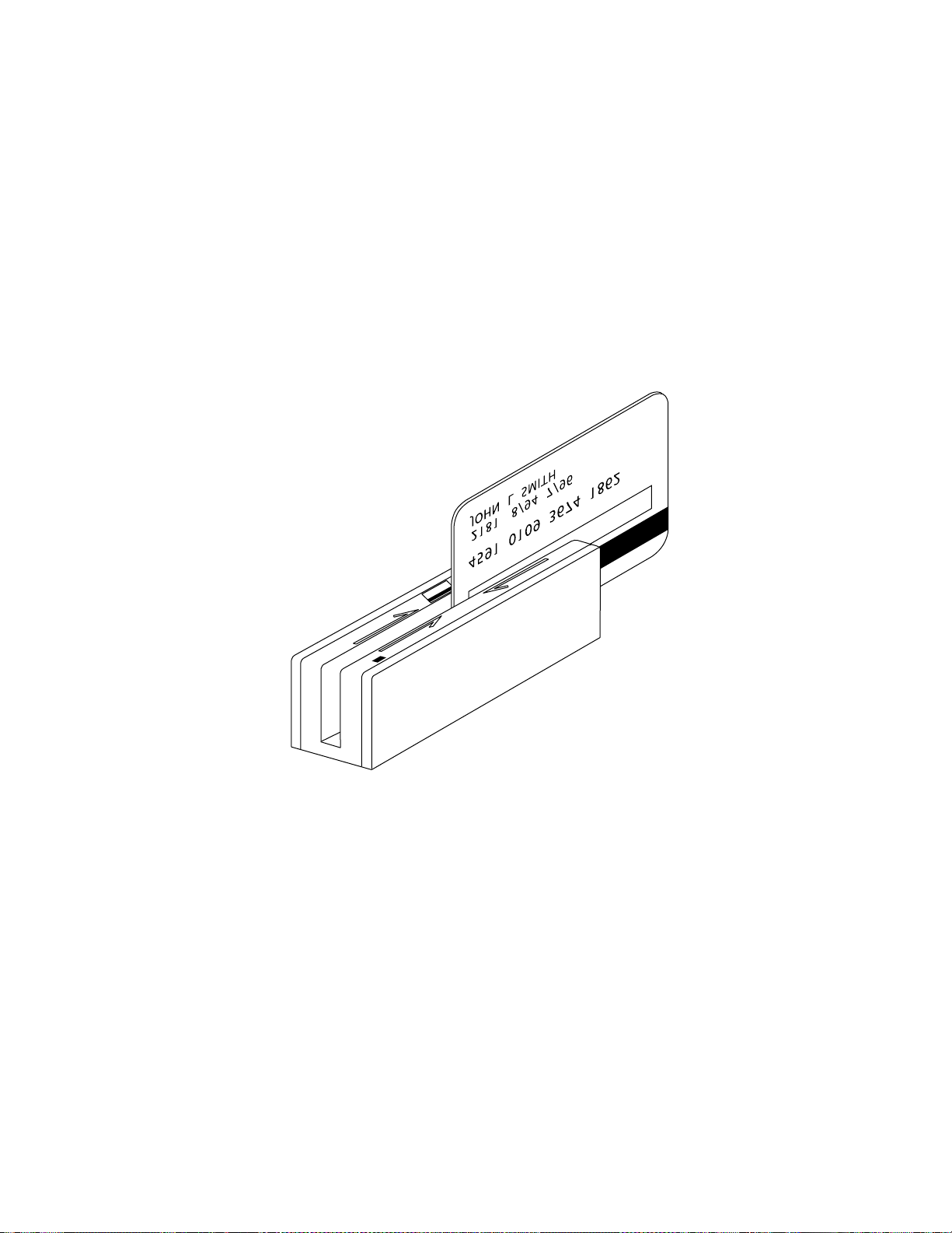
Figure 1-1. USB Swipe Reader
56
Page 60

SECTION 1. FEATURES AND SPECIFICATIONS
The USB (Universal Serial Bus) Swipe Reader is a compact magnetic stripe card reader which
conforms to ISO standards. The Reader is compatible with the PC series of personal computers
or any device with a USB interface. A card is read by sliding it, stripe down and facing the LED
side, through the slot either forward or backward.
A LED (Light Emitting Diode) indicator on the Reader panel provides the operator with
continuous status of the Reader operations.
The reader conforms to the USB Human Interface Device (HID) Class specification Version 1.1.
This allows host applications designed for the latest versions of Windows 98, Me, 2000 to easily
communicate to the device using standard Windows API calls that communicate to the device
through the HID driver that comes with Windows.
Unlike HID keyboard emulation readers, this device does not use keyboard emulation. It
behaves like a vendor defined HID device so that a direct communication path can be established
between the Host application and the device without interference such as keystrokes from other
HID devices.
A demo program with its source code is available, written in Visual Basic, that exercises the
device using the standard Windows API.
FEATURES
Major features of the Swipe Reader are as follows:
• Powered through the USB – no external power supply required
• Hardware Compatible with PC or any computer or terminal with a USB interface
• Bi-directional card reading
• Reads encoded data that meets ANSI/ISO/CDL/AAMVA standards and others such as ISO
track 1 format on track 2 or 3.
• Reads up to three tracks of card data
• LED for status
• Compatible with USB specification Revision 1.1
• Compatible with HID specification Version 1.1
• Can use standard Windows HID driver for communications. No third part device driver is
required.
• Programmable USB serial number descriptor
• Programmable USB Interrupt In Endpoint polling interval
• Non-volatile flash EEPROM memory for property storage
• Built-in 6 foot USB cable
57
Page 61

USB Swipe Reader
CONFIGURATIONS
The Configurations are as follows:
Part Number Tracks Color
P/N 21040101 TK 1,2,3 Pearl White
P/N 21040102 TK 1,2,3 Black
P/N 21040103 TK 1,2 Pearl White
P/N 21040104 TK 1,2 Black
P/N 21040105 TK 2 Pearl White
P/N 21040106 TK 2 Black
ACCESSORIES
The accessories are as follows:
Part Number Description
21042806 USB MSR Demo Program with Source Code (Diskette)
99510026 USB MSR Demo Program with Source Code (WEB)
REFERENCE DOCUMENTS
Axelson, Jan. USB Complete, Everything You Need to Develop Custom USB Peripherals, 1999.
Lakeview Research, 2209 Winnebago St., Madison WI 53704, 396pp., http://www.lvr.com.
USB Human Interface Device (HID) Class Specification Version 1.1.
USB (Universal Serial Bus) Specification, Version 1.1, Copyright 1998 by Compaq Computer
Corporation, Intel Corporation, Microsoft Corporation, NEC Corporation.
USB Implementers Forum, Inc., www.usb.org.
SPECIFICATIONS
Table 1-2 lists the specifications for the Port Powered Swipe Reader. Figure 1-2 shows the
dimensions for the standard product. Other sizes are available by special order.
58
Page 62

Section 1. Features and Specifications
Table 1-2. Specifications
Reference Standards ISO 7810 and ISO 7811/CDL/ AAMVA*
Power Input 5V From USB port
Recording Method Two-frequency coherent phase (F2F)
Message Format ASCII
Card Speed 3 to 50 IPS
MTBF Electronics: 125,000 hours. Head: 1,000,000 passes
ELECTRICAL
Current
Normal Mode
Suspend Mode
Weight 4.5 oz. (127.57 g)
Cable length 6ft.
Connector USB Type A plug
Temperature
Operating 32oF to 131oF (0oC to 55oC)
Storage -22oF to 158oF (-30oC to 70oC)
Humidity
Operating 10% to 90% noncondensing
Storage Up to 100% noncondensing
Altitude
Operating 0-10,000 ft. (0-3048 m.)
Storage 0-50,000 ft. (0-15240 m.)
* ISO (International Standards Organization), CDL (California Drivers License), and AAMVA (American
Association of Motor Vehicle Administrators).
30mA
300uA
MECHANICAL (STANDARD PRODUCT)
ENVIRONMENTAL
Figure 1-2. Dimensions
59
Page 63

USB Swipe Reader
60
Page 64

SECTION 2. INSTALLATION
This section describes the cable connection, the Windows Plug and Play Setup, and the physical
mounting of the unit.
USB CONNECTION
Connect the USB cable to a USB port on the host. The Reader, LED Indicator, and pin numbers
for the 4-pin connector are shown in Figure 2-1.
14
LED Indicator
Figure 2-1. Reader Cable and Connector
Pin numbers and signal descriptions for the cable shown in the illustration are listed in
Table 1-1.
Table 2-1. 4-Pin Connector
Pin Number Signal Cable Color
1 VCC Red
2 - Data White
3 +Data Green
4 Ground Black
61
Page 65

USB Swipe Reader
WINDOWS PLUG AND PLAY SETUP
On hosts with the Windows operating system, the first time the device is plugged into a specific
USB port, Windows will pop up a dialog box, which will guide you through the process of
installing a device driver for the device. After this process is completed once, Windows will no
longer request this process as long as the device is plugged into the same USB port. The device
driver that Windows will install for this device is the driver used for HID devices and it is part of
the Windows operating system. When the dialog box pops up, follow the instructions given to
you in the dialog box. Sometimes Windows will find all the files it needs on its own without
giving you any prompts. Other times Windows will need to know the location of the files it
needs. If Windows prompts you for the file locations, insert the CD that was used to install
Windows on your PC and point Windows to the root directory of the CD. Windows should find
all the files it needs there.
MOUNTING
The Reader may be mounted with screws or fastening tape as described below.
Caution
The Reader should be mounted such that the bottom (mounting
side) is not exposed to the user. This is because the mounting side
of the reader may be susceptible to electrostatic discharge.
1. The Reader can be mounted on a surface in three ways:
• By two screws through the surface attached to the bottom of the unit and running
the cable on the top of the surface;
• By two screws through the surface attached to the bottom of the unit and by
drilling a hole in the surface for the cable and running the cable through the hole;
• By attaching the unit to the surface with fastening tape and running the cable on
the top of the surface.
Note
The two mounting inserts are 3 mm diameter; 0.5 mm pitch; 6.4
mm deep. The length of the screws used depends on the mounting
surface thickness and the thickness of washers (if used).
The mounting dimensions are shown in Figure 2-2. Determine the method of mounting
required.
62
Page 66

Section 2. Installation
Figure 2-2. Mounting Hole Dimensions For Surface
2. Ensure the Reader is positioned on a flat, accessible surface with at least 4 inches
clearance on either end for room to swipe a card. Orient the Reader so the side with the
LED is facing the direction of intended use.
If fastening tape is to be used, clean the area that the Reader will be mounted on with
isopropyl alcohol. Remove the adhesive protective cover on the fastening tape, and
position the Reader and push down firmly.
3. Mount the Reader.
63
Page 67

USB Swipe Reader
64
Page 68

SECTION 3. OPERATION
This section describes the LED Indicator and Card Read.
LED INDICATOR
The LED indicator will be either off, red, or green. When the device is not powered, the LED
will be off. When the device is first plugged in, the LED will be red. As soon as the device is
plugged in, the host will try to enumerate the device. Once the device is enumerated the LED
will turn green indicating that the device is ready for use. When a card is being swiped, the LED
will turn off temporarily until the swipe is completed. If there are no errors decoding the card
data then the LED will turn green. If there are any errors decoding the card data, the LED will
turn red for approximately two seconds to indicate that an error occurred and then turn green.
Anytime the host puts the device into suspend mode, the LED will turn off. Once the host takes
the device out of suspend mode, the LED will return to the state it was in prior to entering
suspend mode.
CARD READ
A card may be swiped through the Reader slot when the LED is green. The magnetic stripe must
face toward the front (the side with the LED) and may be swiped in either direction. If there is
data encoded on the card, the device will attempt to decode the data and then send the results to
the host via a USB HID input report. After the results are sent to the host, the device will be
ready to read the next card.
65
Page 69

USB Swipe Reader
66
Page 70

SECTION 4. USB COMMUNICATIONS
This device conforms to the USB specification revision 1.1. This device also conforms with the
Human Interface Device (HID) class specification version 1.1. The device communicates to the
host as a vendor defined HID device. The details about how the card data and commands are
structured into HID reports follow later in this section. The latest versions of the Windows
operating systems, Windows 98, Me, and 2000, all come with a standard Windows USB HID
driver. Windows applications that communicate to this device can be easily developed. These
applications can communicate to the device using standard windows API calls that communicate
to the device using the standard Windows USB HID driver. These applications can be easily
developed using compilers such as Microsoft’s Visual Basic or Visual C++. A demonstration
program and its source code, written in Visual Basic, that communicates with this device is
available. This demo program can be used to test the device and it can be used as a guide for
developing other applications. More details about the demo program follow later in this
document.
It is strongly recommended that application software developers become familiar with the HID
specification the USB specification before attempting to communicate with this device. This
document assumes that the reader is familiar with these specifications. These specifications can
be downloaded free from www.usb.org
This is a full speed USB device. This device has a number of programmable configuration
properties. These properties are stored in non-volatile EEPROM memory. These properties can
be configured at the factory or by the end user. The device has an adjustable endpoint descriptor
polling interval value that can be set to any value in the range of 1ms to 255ms. This property
can be used to speed up or slow down the card data transfer rate. The device also has an
adjustable serial number descriptor. More details about these properties can be found later in this
document in the command section.
The device will go into suspend mode when directed to do so by the host. The device will
wakeup from suspend mode when directed to do so by the host. The device does not support
remote wakeup.
This device is powered from the USB bus. Its vendor ID is 0x0801 and its product ID is 0x0002.
HID USAGES
HID devices send data in reports. Elements of data in a report are identified by unique identifiers
called usages. The structure of the device’s reports and the device’s capabilities are reported to
the host in a report descriptor. The host usually gets the report descriptor only once, right after
the device is plugged in. The report descriptor usages identify the devices capabilities and report
structures. For example, a device could be identified as a keyboard by analyzing the device’s
report descriptor. Usages are four byte integers. The most significant two bytes are called the
usage page and the least significant two bytes are called usage IDs. Usages that are related can
share a common usage page. Usages can be standardized or they can be vendor defined.
Standardized usages such as usages for mice and keyboards can be found in the HID Usage
Tables document and can be downloaded free at www.usb.org
have a usage page in the range 0xff00 – 0xffff. All usages for this device use vendor defined
magnetic stripe reader usage page 0xff00. The usage IDs for this device are defined in the
.
. Vendor defined usages must
67
Page 71

USB Swipe Reader
following table. The usage types are also listed. These usage types are defined in the HID
Usage Tables document.
Magnetic Stripe Reader usage page 0xff00:
Usage ID
(Hex)
1 Decoding reader device Collection None
20 Track 1 decode status Data Input
21 Track 2 decode status Data Input
22 Track 3 decode status Data Input
28 Track 1 data length Data Input
29 Track 2 data length Data Input
2A Track 3 data length Data Input
30 Track 1 data Data Input
31 Track 2 data Data Input
32 Track 3 data Data Input
38 Card encode type Data Input
20 Command message Data Feature
Usage Name Usage
Type
Report
Type
REPORT DESCRIPTOR
The HID report descriptor is structured as follows:
Item Value(Hex)
Usage Page (Magnetic Stripe
Reader)
Usage (Decoding reader device) 09 01
Collection (Application) A1 01
Logical Minimum (0) 15 00
Logical Maximum (255) 26 ff 00
Report Size (8) 75 08
Usage (Track 1 decode status) 09 20
Usage (Track 2 decode status) 09 21
Usage (Track 3 decode status) 09 22
Usage (Track 1 data length) 09 28
Usage (Track 2 data length) 09 29
Usage (Track 3 data length) 09 2A
06 00 FF
(Continued)
68
Page 72

Section 4. USB Communications
Item Value(Hex)
Usage (Card encode type) 09 38
Report Count (7) 95 07
Input (Data, Variable, Absolute, Bit
Field)
Usage (Track 1 data) 09 30
Report Count (110) 95 6E
Input (Data, Variable, Absolute,
Buffered Bytes)
Usage (Track 2 data) 09 31
Report Count (110) 95 6E
Input (Data, Variable, Absolute,
Buffered Bytes)
Usage (Track 3 data) 09 32
Report Count (110) 95 6E
Input (Data, Variable, Absolute,
Buffered Bytes)
Usage (Command message) 09 20
Report Count (24) 95 18
Feature (Data, Variable, Absolute,
Buffered Bytes)
End Collection C0
81 02
82 02 01
82 02 01
82 02 01
B2 02 01
CARD DATA
Card data is only sent to the host on the Interrupt In pipe using an Input Report. The device will
send only one Input Report per card swipe. If the host requests data from the device when no
data is available, the device will send a Nak to the host to indicate that it has nothing to send.
When a card is swiped, the Input Report will be sent even if the data is not decodable. The
following table shows how the input report is structured.
Offset Usage Name
0 Track 1 decode status
1 Track 2 decode status
2 Track 3 decode status
3 Track 1 data length
4 Track 2 data length
5 Track 3 data length
6 Card encode type
7 – 116 Track 1 data
117 – 226 Track 2 data
227 - 336 Track 3 data
69
Page 73

USB Swipe Reader
TRACK 1 DECODE STATUS
Bits 7-1 0
Value Reserved Error
This is a one-byte value, which indicates the status of decoding track 1. Bit position zero
indicates there was an error decoding track 1 if the bit is set to 1. If it is zero, then no error
occurred. If a track has data on it that is not noise, and it is not decodable, then a decode error is
indicated. If a decode error is indicated, the corresponding track data length value for the track
that has the error will be set to zero and no valid track data will be supplied.
TRACK 2 DECODE STATUS
Bits 7-1 0
Value Reserved Error
This is a one-byte value, which indicates the status of decoding track 2. Bit position zero
indicates if there was an error decoding track 2 if this bit is set to one. If it is zero, then no error
occurred. If a track has data on it that is not noise, and it is not decodable, then a decode error is
indicated. If a decode error is indicated, the corresponding track data length value for the track
that has the error will be set to zero and no valid track data will be supplied.
TRACK 3 DECODE STATUS
Bits 7-1 0
Value Reserved Error
This is a one-byte value, which indicates the status of decoding track 3. Bit position zero
indicates there was an error decoding track 3 if this bit is set to one. If it is zero, then no error
occurred. If a track has data on it that is not noise, and it is not decodable, then a decode error is
indicated. If a decode error is indicated, the corresponding track data length value for the track
that has the error will be set to zero and no valid track data will be supplied.
TRACK 1 DATA LENGTH
This one byte value indicates how many bytes of decoded card data are in the track 1 data field.
This value will be zero if there was no data on the track or if there was an error decoding the
track.
TRACK 2 DATA LENGTH
This one byte value indicates how many bytes of decoded card data are in the track 2 data field.
This value will be zero if there was no data on the track or if there was an error decoding the
track.
TRACK 3 DATA LENGTH
This one byte value indicates how many bytes of decoded card data are in the track 3 data field.
This value will be zero if there was no data on the track or if there was an error decoding the
track.
70
Page 74

Section 4. USB Communications
CARD ENCODE TYPE
This one byte value indicates the type of encoding that was found on the card. The following
table defines the possible values.
Value Encode Type Description
0 ISO/ABA ISO/ABA encode format
1 AAMVA AAMVA encode format
2 CADL CADL encode format
3 Blank The card is blank.
4 Other The card has a non-standard encode format. For example,
ISO/ABA track 1 format on track 2.
5 Undetermined The card encode type could not be determined because no
tracks could be decoded.
6 None No decode has occurred. This type occurs if no magnetic stripe
data has been acquired since the data has been cleared or
since the device was powered on. This device only sends an
Input report when a card has been swiped so this value will
never occur.
TRACK DATA
If decodable track data exits for a given track, it is located in the track data field that corresponds
to the track number. The length of each track data field is fixed at 110 bytes, but the length of
valid data in each field is determined by the track data length field that corresponds to the track
number. Track data located in positions greater that the track data length field indicates are
undefined and should be ignored. The HID specification requires that reports be fixed in size,
but the number of bytes encoded on a card may vary. Therefore, the Input Report always
contains the maximum amount of bytes that can be encoded on the card and the number of valid
bytes in each track is indicated by the track data length field. The track data is decoded and
converted to ASCII. The track data includes all data starting with the start sentinel and ending
with the end sentinel.
TRACK 1 DATA
This field contains the decoded track data for track 1.
TRACK 2 DATA
This field contains the decoded track data for track 2.
TRACK 3 DATA
This field contains the decoded track data for track 3.
71
Page 75

USB Swipe Reader
COMMANDS
Most host applications do not need to send commands to the device. Most host applications
only need to obtain card data from the device as described previously in this section. This
section of the manual can be ignored by anyone who does not need to send commands to the
device.
Command requests and responses are sent to and received from the device using feature reports.
Command requests are sent to the device using the HID class specific request Set_Report. The
response to a command is retrieved from the device using the HID class specific request
Get_Report. These requests are sent over the default control pipe. When a command request is
sent, the device will Nak the Status stage of the Set_Report request until the command is
completed. This insures that as soon as the Set_Report request is completed, the Get_Report
request can be sent to get the command response. The usage ID for the command message was
shown previously in the Usage Table.
The following table shows how the feature report is structured for command requests:
Offset Field Name
0 Command Number
1 Data Length
2 – 23 Data
The following table shows how the feature report is structured for command responses.
Offset Field Name
0 Result Code
1 Data Length
2 – 23 Data
COMMAND NUMBER
This one byte field contains the value of the requested command number. The following table
lists all the existing commands.
Value Command Number Description
0 GET_PROPERTY Sets a property in the device
1 SET_PROPERTY Gets a property from the device
DATA LENGTH
This one byte field contains the length of the valid data contained in the Data field.
DATA
This multi-byte field contains command data if any. Note that the length of this field is fixed at
22 bytes. Valid data should be placed in the field starting at offset 2. Any remaining data after
the valid data should be set to zero. This entire field must always be set even if there is no valid
data. The HID specification requires that Reports be fixed in length. Command data may vary
in length. Therefore, the Report should be filled with zeros after the valid data.
72
Page 76

Section 4. USB Communications
RESULT CODE
This one byte field contains the value of the result code. There are two types of result codes:
generic result codes and command specific result codes. Generic result codes always have the
most significant bit set to zero. Generic result codes have the same meaning for all commands
and can be used by any command. Command specific result codes always have the most
significant bit set to one. Command specific result codes are defined by the command that uses
them. The same code can have different meanings for different commands. Command specific
result codes are defined in the documentation for the command that uses them. Generic result
codes are defined in the following table.
Value Result Code Description
0 SUCCESS The command completed successfully.
1 FAILURE The command failed.
2 BAD_PARAMETER The command failed due to a bad
parameter or command syntax error.
GET AND SET PROPERTY COMMANDS
The Get Property command gets a property from the device. The Get Property command
number is 0.
The Set Property command sets a property in the device. The Set Property command number
is 1.
The Get and Set Property command data fields for the requests and responses are structured as
follows:
Get Property Request Data:
Data Offset Value
0 Property ID
Get Property Response Data:
Data Offset Value
0 – n Property Value
Set Property Request Data:
Data Offset Value
0 Property ID
1 – n Property Value
Set Property Response Data:
None
The result codes for the Get and Set Property commands can be any of the codes list in the
generic result code table.
73
Page 77

USB Swipe Reader
Property ID is a one byte field that contains a value that identifies the property. The following
table lists all the current property ID values:
Value Property ID Description
0 SOFTWARE_ID The device’s software identifier
1 SERIAL_NUM The device’s serial number
2 POLLING_INTERVAL The interrupt pipe’s polling interval
The Property Value is a multiple byte field that contains the value of the property. The number
of bytes in this field depends on the type of property and the length of the property. The
following table lists all of the property types and describes them.
Property Type Description
Byte This is a one byte value. The valid values depend on the property.
String This is a multiple byte ASCII string. Its length can be zero to a
maximum length that depends on the property. The value and
length of the string does not include a terminating NUL character.
SOFTWARE_ID PROPERTY
Property ID: 0
Property Type: String
Length: Fixed at 11 bytes
Get Property: Yes
Set Property: No
Description: This is an 11 byte read only property that identifies the software part
number and version for the device. The first 8 bytes represent the part number and the last 3
bytes represent the version. For example this string might be “21042804A02”. Examples
follow:
Example Get SOFTWARE_ID property Request (Hex):
Cmd Num Data Len Prp ID
00 01 00
Example Get SOFTWARE_ID property Response (Hex):
Result Code Data Len Prp Value
00 01 32 31 30 34 32 38 30 34 41 30 32
74
Page 78

Section 4. USB Communications
SERIAL_NUM PROPERTY
Property ID: 1
Property Type: String
Length: 0 – 15 bytes
Get Property: Yes
Set Property: Yes
Default Value: The default value is no string with a length of zero.
Description: The value is an ASCII string that represents the device’s serial number.
This string can be 0 – 15 bytes long. This property is stored in non-volatile EEPROM memory
so it will not change when the unit is power cycled. The value of this property, if any, will be
sent to the host when the host requests the USB string descriptor. When this property is
changed, the unit must be power cycled to have these changes take effect for the USB descriptor.
If a value other than the default value is desired, it can be set by the factory upon request.
Examples follow.
Example Set SERIAL_NUM property Request (Hex):
Cmd Num Data Len Prp ID Prp Value
01 04 01 31 32 33
Example Set SERIAL_NUM property Response (Hex):
Result Code Data Len Data
00 00
Example Get SERIAL_NUM property Request (Hex):
Cmd Num Data Len Prp ID
00 01 01
Example Get SERIAL_NUM property Response (Hex):
Result Code Data Len Prp Value
00 03 31 32 33
POLLING_INTERVAL PROPERTY
Property ID: 2
Property Type: Byte
Length: 1 byte
Get Property: Yes
Set Property: Yes
Default Value: 10
Description: The value is a byte that represents the devices polling interval for the
Interrupt In Endpoint. The value can be set in the range of 1 – 255 and has units of milliseconds.
The polling interval tells the host how often to poll the device for card data packets. For
example, if the polling interval is set to 10, the host will poll the device for card data packets
every 10ms. This property can be used to speed up or slow down the time it takes to send card
data to the host. The trade-off is that speeding up the card data transfer rate increases the USB
bus bandwidth used by the device, and slowing down the card data transfer rate decreases the
USB bus bandwidth used by the device. This property is stored in non-volatile EEPROM
memory so it will not change when the unit is power cycled. The value of this property, if any,
75
Page 79

USB Swipe Reader
will be sent to the host when the host requests the device’s USB endpoint descriptor. When this
property is changed, the unit must be power cycled to have these changes take effect for the USB
descriptor. If a value other than the default value is desired, it can be set by the factory upon
request. Examples follow:
Example Set POLLING_INTERVAL property Request (Hex):
Cmd Num Data Len Prp ID Prp Value
01 02 02 0A
Example Set POLLING_INTERVAL property Response (Hex):
Result Code Data Len Data
00 00
Example Get POLLING_INTERVAL property Request (Hex):
Cmd Num Data Len Prp ID
00 01 02
Example Get POLLING_INTERVAL property Response (Hex):
Result Code Data Len Prp Value
00 01 0A
76
Page 80

SECTION 5. DEMO PROGRAM
The demo program, which is written in Visual Basic, can be used to do the following:
• Read cards from the device and view the card data
• Send command requests to the device and view the command responses
• Guide application developers in their application development by providing examples, in
source code, of how to properly communicate with the device using the standard Windows
APIs
The part numbers for the demo program can be found in this document in Section 1 under
Accessories.
INSTALLATION
To install the demo program, run the setup.exe file and follow the instructions given on the
screen.
OPERATION
To operate the demo program perform the following steps:
• Plug the device into a USB port on the host
• If this is the first time the device has been plugged into the host, then follow the instructions
on the screen for installing the Windows HID device driver. This is explained in more detail
in the installation section of this document.
• Run the demo program.
• To read cards and view the card data, click on the Read Cards button and swipe a card when
prompted to do so.
• When finished reading cards, close the dialog box.
• To send commands to the device, click on the send commands button.
• Enter a command in the Message edit box. All data entered should be in hexadecimal bytes
with a space between each byte. Enter the command number followed by the command data
if there is any. The application will automatically calculate and send the command data
length for you. For example, to send the GET_PROPERTY command for property
SOFTWARE_ID enter 00 00.
• Press Enter or click on Send message to send the command and receive the result.
• The command request and the command result will be displayed in the Communications
Dialog edit box.
• The Clear Dialog button clears the Communication Dialog edit box.
77
Page 81

USB Swipe Reader
SOURCE CODE
Source code is included with the demo program. It can be used as a guide for application
development. It is described in detail, with comments, to assist developers. The book USB
Complete by Jan Axelson is also a good guide for application developers, especially the chapter
on Human Interface Device Host Applications (see “Reference Documents” in Section 1).
78
Page 82

MAGTEK DEVICE DRIVERS
FOR WINDOWS
PROGRAMMING REFERENCE MANUAL
Manual Part Number: 99875125 Rev 6
NOVEMBER 2001
20725 South Annalee Avenue
Carson, CA 90746
Phone: (310) 631-8602
FAX: (310) 631-3956
Technical Support: (888) 624-8350
www.MagTek.com
Page 83

Copyright 1996-2001
MAG-TEK, Inc.
Printed in the United States of America
Information in this document is subject to change without notice. No part of this document may
be reproduced or transmitted in any form or by any means, electronic or mechanical, for any
purpose, without the express written permission of Mag-Tek, Inc.
MagTek is a registered trademark of Mag-Tek, Inc.
Microsoft, MS, MSDOS, MSCOMM and Microsoft Visual Basic are registered trademarks of
Microsoft Corporation; Windows and Windows 95 are trademarks of Microsoft Corporation.
REVISIONS
Rev
Number
1 20 Nov 98 Initial Release
2 16 Feb 99 Sec 1: Editorial comments for clarification; Sec 2: Added c_wr_secure
3 27 Apr 99 Global: Changed names of Mt-211 and MT-215 to port powered
4 21 Oct 99 Sec 1: added: part numbers of media, special commands, MICR
5 14 Dec 99 Appendix A: Added statement about "Long File Names" under "Adding
6 30 Nov 01 Editorial changes throughout and added Software Version MTD 1.10,
Date Notes
and trks 1, 2, and 3; Sec 3: Editorial comments for clarification;
Appendix A: Added MT-85 and clarified tables; Appendix D: Added
c_wr_secure and tks 1, 2, and 3 and MT-85 Encoder sheet.
readers; Sec 3: Added card insertion note to event; Sec 4: Added this
section, Data Parsing. Appendix A: Changed file names. Appendix D.
Changed names.
material; Sec 2: changed properties table; Sec 3: added errors 45 and
60 to write command; Sec 4: added descriptions to language format;
updated default formats; Sec 5: replaced Visual Basic example;
Appendix A; Completely revised; Appendix D: added applied_fmt to all
forms.
MagTek Device Drivers" General Notes number 4; added statement to
"Completing the Installation" about sharing a single port; Edited
"Removing the Drivers"; added "Configuration Examples of NT Drivers."
Appendix D: Under IntelliPIN PINPad and MSR, added statement under
Remarks about IntelliPIN driver; under MiniWedge MSR added
statement about ASCII and Character Conversion.
which includes Windows ME/2000/XP.
80
Page 84

Limited Warranty
Mag-Tek, Inc. (hereinafter “Mag-Tek”) warrants this Mag-Tek product IN ITS ENTIRETY, to be in good
working order for a period of 90 days from the date of purchase from Mag-Tek. Should this product fail
to be in good working order at any time during this warranty period, Mag-Tek will, at its option, repair or
replace this product at no additional charge except as set forth below. Repair parts and replacement
products will be furnished on an exchange basis and will be either reconditioned or new. All replaced
parts and products become the property of Mag-Tek. This limited warranty does not include service to
repair damage to the product resulting from accident, disaster, misuse, abuse, or non-Mag-Tek
modification of the product.
Limited Warranty service may be obtained by delivering the product during the warranty period to MagTek (20725 S. Annalee Ave., Carson, CA 90746). If this product is delivered by mail, you agree to insure
the product or assume the risk of loss or damage in transit, to prepay shipping charges to the warranty
service location and to use the original shipping container or equivalent.
ALL EXPRESS AND IMPLIED WARRANTIES FOR THIS PRODUCT, INCLUDING THE
WARRANTIES OF MERCHANTABILITY AND FITNESS FOR A PARTICULAR PURPOSE, ARE
LIMITED IN DURATION TO A PERIOD OF 90 DAYS FROM THE DATE OF PURCHASE, AND
NO WARRANTIES, WHETHER EXPRESS OR IMPLIED, WILL APPLY AFTER THIS PERIOD,
EXCEPT AS PROVIDED IN THE PRECEDING SENTENCE. EACH PURCHASER UNDERSTANDS
THAT THE MAG-TEK PRODUCT IS OFFERED AS IS.
IF THIS PRODUCT IS NOT IN GOOD WORKING ORDER AS WARRANTED ABOVE, YOUR
SOLE REMEDY SHALL BE REPAIR OR REPLACEMENT AS PROVIDED ABOVE. IN NO EVENT
WILL MAG-TEK BE LIABLE TO YOU FOR ANY DAMAGES, INCLUDING ANY LOST PROFITS,
LOST SAVINGS OR OTHER INCIDENTAL OR CONSEQUENTIAL DAMAGES ARISING OUT OF
THE USE OF OR INABILITY TO USE SUCH PRODUCT, EVEN IF MAG-TEK HAS BEEN
ADVISED OF THE POSSIBILITY OF SUCH DAMAGES, OR FOR ANY CLAIM BY ANY OTHER
PARTY.
THIS WARRANTY GIVES YOU SPECIFIC LEGAL RIGHTS, AND YOU MAY ALSO HAVE
OTHER RIGHTS WHICH VARY FROM STATE TO STATE.
81
Page 85

TABLE OF CONTENTS
SECTION 1. OVERVIEW ..............................................................................................................87
PROBLEMS WITH CONTROLLING DEVICES.........................................................................87
BENEFITS OF A CONTROL LANGUAGE AND DRIVER.........................................................88
LANGUAGE OVERVIEW...........................................................................................................89
Properties...............................................................................................................................89
COMMANDS..............................................................................................................................90
TYPICAL OPERATION..............................................................................................................91
Open a device........................................................................................................................91
Query the device’s capabilities ..............................................................................................91
Prepare the device for work...................................................................................................91
Use the device .......................................................................................................................91
Close the device ....................................................................................................................92
METHODS OF ACCESSING THE DEVICE ..............................................................................92
Obtaining access to the device..............................................................................................92
Interacting with the device .....................................................................................................93
Releasing access to the device .............................................................................................94
ERRORS AND ERROR PROCESSING....................................................................................94
HANDLING SPECIAL COMMANDS..........................................................................................95
FILE PROPERTIES ...................................................................................................................95
INSTALLATION..........................................................................................................................96
MICR Format Numbers..........................................................................................................96
SECTION 2. PROPERTIES ..........................................................................................................97
account_no ............................................................................................................................97
amount...................................................................................................................................97
applied_fmt ............................................................................................................................97
c_card_stat ............................................................................................................................97
c_keypress.............................................................................................................................97
c_keystring.............................................................................................................................97
c_magnetic.............................................................................................................................97
c_mechanics..........................................................................................................................97
c_pin.......................................................................................................................................97
c_smart ..................................................................................................................................97
c_tracks..................................................................................................................................97
c_write....................................................................................................................................98
c_wr_secure...........................................................................................................................98
capitalize ................................................................................................................................98
card_stat ................................................................................................................................98
chk_account...........................................................................................................................98
chk_amount ...........................................................................................................................98
chk_bankid.............................................................................................................................98
chk_data ................................................................................................................................98
chk_format .............................................................................................................................98
chk_mod10 ............................................................................................................................98
chk_number ...........................................................................................................................98
chk_routing ............................................................................................................................98
chk_status..............................................................................................................................98
chk_transit..............................................................................................................................98
cmd_pending .........................................................................................................................98
dblpinentry .............................................................................................................................98
dev_status..............................................................................................................................98
dev_version............................................................................................................................98
enable_cmc7..........................................................................................................................98
82
Page 86

enc_key..................................................................................................................................99
enc_key_sn............................................................................................................................99
enc_mode ..............................................................................................................................99
entry_echo .............................................................................................................................99
entry_len ................................................................................................................................99
entry_tout...............................................................................................................................99
events_on ..............................................................................................................................99
invalcmdrsp............................................................................................................................99
key_parity...............................................................................................................................99
lasterr .....................................................................................................................................99
max_pin_len...........................................................................................................................99
msg1 - msg4 ..........................................................................................................................99
oper_tout................................................................................................................................100
pin_blk_fmt.............................................................................................................................100
pinfilldig ..................................................................................................................................100
port_name..............................................................................................................................100
pwroffdelay.............................................................................................................................100
s_down_tout...........................................................................................................................100
track1ss..................................................................................................................................100
trivpinchk................................................................................................................................100
trk_enable ..............................................................................................................................100
trk1data..................................................................................................................................100
trk2data..................................................................................................................................100
trk3data..................................................................................................................................100
visa_mac1..............................................................................................................................100
visa_mac2..............................................................................................................................100
visa_mac3..............................................................................................................................100
wr_coer ..................................................................................................................................100
wr_secure ..............................................................................................................................100
xact_type................................................................................................................................100
SECTION 3. COMMANDS............................................................................................................101
DATA FORMAT .........................................................................................................................101
RESPONSES.............................................................................................................................101
Notation Conventions.............................................................................................................102
COMMAND DESCRIPTIONS ....................................................................................................102
cancel.....................................................................................................................................102
display....................................................................................................................................103
echo .......................................................................................................................................103
event ......................................................................................................................................104
get ..........................................................................................................................................104
load_key.................................................................................................................................105
rawrecv ..................................................................................................................................106
rawsend .................................................................................................................................107
rawxact...................................................................................................................................107
read........................................................................................................................................108
Read Arguments .......................................................................................................................109
reset .......................................................................................................................................112
set ..........................................................................................................................................112
ver ..........................................................................................................................................112
write........................................................................................................................................113
SECTION 4. MAGNETIC CARD DATA PARSING ......................................................................115
GOALS.......................................................................................................................................115
ASSUMPTIONS.........................................................................................................................115
83
Page 87

DESCRIPTION...........................................................................................................................116
LANGUAGE FORMAT...............................................................................................................117
Format Name.........................................................................................................................117
Format Template....................................................................................................................117
Format Rules .........................................................................................................................117
DEFAULT FORMATS ................................................................................................................121
EXAMPLE ..................................................................................................................................122
Retrieving properties from a magnetic card...........................................................................122
SECTION 5. EXAMPLE APPLICATIONS ....................................................................................125
PROGRAMMING HINTS ...........................................................................................................125
VISUAL BASIC EXAMPLE.........................................................................................................125
C++ EXAMPLE ..........................................................................................................................131
POWER BUILDER EXAMPLE...................................................................................................136
APPENDIX A. INSTALLATION AND SETUP..............................................................................139
INSTALLING DEVICE DRIVERS (W95/98/ME) ........................................................................140
Adding the First Device Driver (W95/98/ME).........................................................................141
Adding Another Device Driver (W95/98/ME) .........................................................................141
Updating an Installed Device Driver (W95/98/ME)................................................................142
Completing the Installation (W95/98/ME) ..............................................................................142
Modifying A Device Driver's Settings (W95/98/ME)...............................................................143
Removing The Drivers (W95/98/ME).....................................................................................145
INSTALLING DEVICE DRIVERS (WNT)...................................................................................149
Installing the Driver Binaries (WNT) ......................................................................................150
Uninstalling the Drivers (WNT) ..............................................................................................150
INSTALLING DEVICE DRIVERS (W2000/XP)..........................................................................151
Installing the Driver Binaries (W2000/XP) .............................................................................152
Uninstalling the Drivers (W2000/XP) .....................................................................................153
Uninstalling the Keyboard Hook Driver – (W2000/XP)..........................................................153
WINDOWS NT/W2000/XP CONFIGURATION UTILITY...........................................................154
Adding a Keyboard Device (WNT/2000/XP)..........................................................................154
Adding a Serial Device (WNT/W2000/XP).............................................................................155
Adding an ‘IntelliPIN MICR Aux’ Device (WNT/W2000/XP) ..................................................155
Viewing the List of Configured Devices (WNT/W2000/XP) ...................................................156
Using the MTCFG Utility (WNT/W2000/XP) ..........................................................................156
Command syntax summary...................................................................................................157
Displaying Configuration Information (WNT/W2000/XP).......................................................157
Adding New Devices (WNT/W2000/XP)................................................................................157
Configuration Examples of NT/W2000/XP ............................................................................157
Modifying a Device Driver's Settings (WNT/W2000/XP) .......................................................158
Removing a Device (WNT/W2000/XP)).................................................................................159
APPENDIX B. COMMAND LIST SUMMARY...............................................................................161
APPENDIX C. STATUS CODES ..................................................................................................163
APPENDIX D. DEVICE DRIVER SUMMARIES ...........................................................................165
INTELLIPIN PINPAD & MSR .....................................................................................................166
MAGWEDGE SWIPE READER.................................................................................................167
MINIWEDGE MSR.....................................................................................................................168
MICR+ CHECK READER & MSR..............................................................................................169
MINI MICR CHECK READER & MSR .......................................................................................170
PORT-POWERED RS-232 SWIPE READER ...........................................................................171
PORT-POWERED RS-232 INSERTION READER ...................................................................172
MT-85 LOCO ENCODER...........................................................................................................173
84
Page 88

MT-95 HICO ENCODER............................................................................................................174
INDEX.............................................................................................................................................175
FIGURES
Figure 1-1. MagTek Devices and Device Drivers for Windows.....................................................86
Figure A-1. Properties Settings, Windows 95 ................................................................................144
Figure A-2. Advanced Settings, Windows 95.................................................................................144
85
Page 89

MTD
MagTek
Device Drivers
for Windows
Figure 1-1. MagTek Devices and Device Drivers for Windows
86
Page 90

SECTION 1. OVERVIEW
The MagTek Device (MTD) Drivers for Windows is a collection of individual drivers that
support a number of MagTek products. These drivers provide a uniform application interface for
controlling a wide range of MagTek devices. The drivers, combined with a device control
language, solve many of the difficulties application developers face when attempting to control
hardware devices. The difficulties mount when faced with the task of developing an application
that supports an entire product line of devices.
Part Numbers for the MTD are as follows:
Part Number Windows Version Medium
30037385 All CD
99510030 9X/ME Internet* (MTD110-9x-ME)
99510031 NT (MTD110-NT)
99510032 2000/XP (MTD110-2K-XP)
*www.magtek.com
PROBLEMS WITH CONTROLLING DEVICES
The major problems with developing an application that supports an entire product line of
devices are as follows:
• Each MagTek device has a unique set of commands. The commands usually perform
similar functions on a particular class of devices but either differ in syntax or have small
variations in their functionality. An application would have to implement a custom
mechanism to control each device it supported–much like DOS applications had to do to
support various printers.
• Most MagTek devices communicate via data streams, not packets. This means that an
application receives data from the device one character at a time; it only receives partial
command responses. It would be the application’s responsibility to collect the incoming
data and parse it into individual responses.
• Responses from MagTek devices are inherently asynchronous. When an application
sends a command that requires a response, the response from the device arrives (or
worse, begins to arrive) long after the command is sent. The application would have to
either poll the device until all of the response is collected or implement a callback
mechanism to collect and receive it.
• Most MagTek devices maintain a communication protocol of some kind. In addition to
this, the protocols differ between devices. For example, some devices frame responses
with STX and ETX control characters and others simply use a CR or require a checksum
in the frame. To deal with this, an application would have to recognize and implement all
of the various protocols for the devices it supports.
87
Page 91

MagTek Device Drivers for Windows
• MagTek devices are attached to the host in different ways. MagTek devices may be
attached to a serial port, parallel port, to another device or even to the keyboard port. All
these ports differ greatly in nature and would all have to be accessed by the application.
Additionally, meaningful communication with a device attached to the keyboard port
would be tricky at best. This is because the operating system does not provide a means to
send data to the keyboard port nor any mechanism to discriminate between the device
data and manual keystrokes.
BENEFITS OF A CONTROL LANGUAGE AND DRIVER
A device control language is defined to support most of the functionality of all MagTek devices.
As noted previously, most devices of a particular class have similar functionality. The control
language defines a common set of commands that perform these functions in the same way for
all MagTek devices, thus eliminating device-specific coding for most applications. If the need
arises to perform an operation on a device not covered by the common command set, a “raw”
send and receive command can be used to communicate directly with the device, effectively
eliminating any limitations on the amount of control you have over the device.
The control language is based on a simple property/command model. This model is familiar to
most developers who deal with properties and methods in development environments such as
Visual Basic or Delphi. You set up the device by getting and setting properties and operate it by
invoking commands.
The command set presents a synchronous interface to the application even though the device
operates asynchronously, greatly simplifying the effort in retrieving responses from a device.
The pattern is simple: send a command to the device and invoke a read command, which will not
complete until after the entire response is received from the device.
The control language is implemented by a driver, which completes the solution for the
application developer. The driver adds the following benefits:
• Gives easy access to the device. All MagTek devices are presented uniformly as a virtual
serial port, regardless of how they are actually attached to the host.
• Hides the communication protocol. Adding and stripping frames, performing
checksums, detecting and correcting communication errors, etc, are handled completely
by the driver. The application sees only the data that it is interested in and can be assured
that it is free from transport errors.
• Converts the incoming data stream into complete responses. The application receives
data from the device in easy to use packets. The entire response to a command is
received in a single operation.
• Makes it easier to upgrade to a new device. The driver shields you from differences in
the new device’s commands or interface. When upgrading the device, an application can
88
Page 92

Section 1. Overview
usually remain unchanged, even though the new device may be very different from the
old one.
The features of a driver that implement a device control language completely shield an
application developer from the complexities of device-specific functionality.
LANGUAGE OVERVIEW
The device control language is text based and designed to utilize the read and write file I/O
facilities of the underlying operating system. All commands, their responses and properties
consist of text strings that are written to or read from the driver using basic file I/O. The control
language is based on a property/command model that is similar to the notions of properties and
methods as accepted in environments such as Visual Basic or Delphi.
Properties
All properties are accessed in a uniform way: by using a
get (/get prop) or set(/set prop)
command. Properties are either read/write or read only. A set command with a read only
property will fail. All properties are identified by a string name and use strings for their
arguments. Properties defined by the control language fall into the following three groups:
• Capability properties – These properties contain information about the capabilities of a
particular device and are generally read only. They allow an application to query a
device’s capabilities to determine if the device is suitable for a particular task. Included
in this category are
c_check
).
c_cardwpin, c_check, c_pin, and c_magnetic (e. g., /get
• Configuration properties – These properties configure a device for different modes of
operation or may alter the way some commands behave. Because of this, they are usually
readable and writable. They give an application the ability to set up a device for a particular
task that requires a specific, non-default mode of operation. Included in this category are
capitalize, dev_version, and port_name (e.g., /set capitalize 1).
• Device-specific properties −These properties cover configuration requirements that are
not common among MagTek devices, even if the devices belong to the same class. An
application can determine if a particular set of device-specific properties is available by
first querying the device’s capabilities or version. Refer to Appendix D, Device Driver
Summaries, for a particular driver to see how these properties are affected with an
individual device.
Properties can be “action” properties. That is, the driver may execute an action on the device
when a property is set. For example, an application can enable or disable magnetic stripe tracks
by setting the
the device to enable or disable the desired tracks.
trk_enable property. The driver responds by sending one or more commands to
89
Page 93

MagTek Device Drivers for Windows
COMMANDS
Like properties, commands are identified by a string name and have string arguments. All
commands are terminated by line feed <LF> or a carriage return. To invoke a command, an
application simply writes it to the driver in the same manner as writing to a file or serial port. If
the command has a response defined for it, the application reads it from the driver using the same
I/O handle as in the write.
Four types of commands are defined by the device control language:
• Non-interactive – These commands manipulate the device without requiring any
interaction with the user. The property commands
examples of this type.
get and set, reset and ver are
• Interactive – These commands interact with the user. They do not necessarily require the
user to do anything but may only prompt the user to do something.
example of such a command. Others, such as read or write, however, require user
interaction to complete. For example, the user must either swipe a card or cancel the
operation in order to complete a read command.
display is an
• Device-specific – These commands give access to device-specific features. For example,
load_key command is available for MagTek devices that use keys to encrypt data
the
before sending it to the host.
• Raw – These are effectively escape commands. They allow the application to bypass the
driver to perform device-specific operations that are not included in the driver syntax and
not supported elsewhere. With these commands, an application has no limitations on the
amount of control it has over a device. The raw commands can be formatted exactly as
specified in the device documentation. The command bracketing will be inserted by the
driver if required (e.g., <stx> and <etx> will be inserted for certain devices). Three
commands are defined for this type:
data directly to the device, and
the first two.
A small set of interactive and non-interactive commands is all that is required for an application
to perform the most common tasks with these devices. Device-specific or raw commands should
rarely ever be needed.
rawsend and rawrecv, used to send and receive
rawxact, a transactional version that is a combination of
90
Page 94

Section 1. Overview
TYPICAL OPERATION
This section describes a typical pattern that an application developer may use to operate a device.
Although it is the most typical pattern, it is by no means the only viable one. Refer to Section 5,
Example Applications, to see how to use the drivers in various applications.
Open a device
Access to the device is obtained by opening the comxx: port that the device was installed as.
This is not the hardware port that the device may be attached to, but a virtual comxx : port
presented by the driver (e.g., COM5 or higher). A handle is returned by the open function and is
required for all subsequent interactions with the driver. When opened, the driver initializes itself
and, where required, the device.
Some drivers support automatic settings. In this mode, the driver first attempts to communicate
with the device at the previous setting or at the default setting if it is the first time. (The setting
for the initial attempt is grayed out in the manual settings fields.) If the driver does not receive a
response, it will adjust the settings and try again. This sequence continues until the device
responds or until all possible settings have been attempted.
If the driver is set for the automatic mode, it may take considerably longer for the device driver
to detect an error. In particular, if the device is not connected to the specified port or if its power
is off, the device driver may take several seconds attempting all possible settings before it returns
an error. The application program should be tolerant of this delay.
Query the device’s capabilities
The application now queries the device to determine if it can perform the required task. The
capability properties (
c_xxx) are provided for this purpose. For example, if an application
requires the ability to read checks, it can get the c_check property to determine if the device
can read checks.
Prepare the device for work
The device is prepared for operation by setting one or more of the configuration properties. Its
mode of operation and other features are set up by these properties. Setting the
capitalize
property to 1 to cause all data written to or read from a card’s magnetic strip to be capitalized is
an example of this type of initialization. In some cases, modifying a property may cause the
driver to execute functions on the device.
Use the device
The device is now fully initialized ready for operation. Because most tasks with the device
require interaction with the user, the application operates the device using primarily the
interactive commands. A typical scenario is when, in response to some event, the user is
prompted to swipe a card by using the display command, followed by a read command to
91
Page 95

MagTek Device Drivers for Windows
instruct the device to return the card data when swiped. All the facilities of the driver are utilized
during this stage of operation.
Close the device
When the application is finished with the device, it simply closes the port using the handle
obtained when it opened it. The driver shuts down the device if required.
Note
In some cases with Windows 95, the Driver may not be closed
properly. This will leave the port open and will prevent further
communications with that device until the computer is rebooted.
METHODS OF ACCESSING THE DEVICE
This section describes how to use control language commands in a Visual Basic development
environment using the MSComm (Microsoft Communication) component.
Obtaining access to the device
If the MSComm (Microsoft Communication) ActiveX component is used to access the device,
set the
CommPort property to the com port number of the device. Then, set the PortOpen
property to True to open it. The following example shows how:
‘set error handling
On Error Resume Next
‘open the port
Comm.CommPort = 5
Comm.PortOpen = True
If Err.Number <> 0 Then
<<process error>>
End If
on error goto 0
Note
After issuing an Open command, the computer may spend several
seconds attempting to communicate with the device. During this
time the computer will appear to be hung up.
If file I/O access is desired, you have the option of using either the device’s friendly name, such
as
\\.\micr+ (where \\.\ specifies to Windows that this is a device and not a file) or its port
name, COM<5..15>. The friendly name is more intuitive and easier to remember than a port
number; however, the serial method gives the programmer better control of the device. The port
number can be found in the operating system’s device UI. For example, open Control
Panel/System/Device Manager/MagTek and select a specific driver. Under Properties, select the
92
Page 96

Section 1. Overview
Settings tab. This gives both the Friendly Name and the port name (
COM<5-15>). It also
identifies the physical port that will be used to communicate with the device.
Open the device using either of the previous names. Use whatever facility is provided by your
development environment for opening files. For Visual Basic, do the following:
'set error handling
On Error Resume Next
‘open the port for binary access
Open “\\.\micr+” For Binary Access Read Write As #1
If Err.Number <> 0 Then
<<process error>>
End If
on error goto 0
Note
The friendly name of the device, as found in the operating system’s
device UI (Device Manager in Windows 95, for example), must be
prefixed with “\\.\” in order to open the device. If the previous
example did not have the prefix, it would create a file named
micr+ in the current directory–clearly not the desired result.
Interacting with the device
An application interacts with the device by sending commands to the device and reading its
responses. Commands are sent by writing to the opened port and responses from the device or
property requests are retrieved by reading from the port.
To interact with the device using the MSComm component, invoke a command by assigning it to
MSComm’s Output property. The response is received by MSComm’s OnComm event handler
as a comEvReceive event or by directly polling the port. The entire response to a command or
property request is received as a single event.
'submit echo command
Comm.Output = "/echo Hello" + Chr$(10)
Private Sub Comm_OnComm()
‘return if not a receive event
If Comm.CommEvent = comEvReceive Then
‘process received data
a$ = Comm.Input ‘get echo data
Else
<<process non-read event>>
End If
End Sub
If using file I/O access, interaction with the device is indistinguishable from writing to or reading
from a file.
93
Page 97

MagTek Device Drivers for Windows
‘set up error handling
On Error Resume Next
‘submit echo command
Put #1, , "/echo Hello" + Chr$(10)
‘declare an input buffer
a$ = String(2000, Chr$(0))
‘read echo response from device
Get #1, , a$
If Err.Number <> 0 Then
<<process error>>
End If
Note
File I/O interaction with the device is synchronous; the read operation
will block until a response is received from the device or is returned by
the driver (as in a property request). This means that a read command
cannot be canceled because the computer will not accept any new
commands while one is pending. The only exception to this is when the
development environment provides access to the Win32 API, giving the
application the ability to use overlapped file I/O.
Releasing access to the device
Releasing access to the device is very simple. If using MSComm, close the device by setting its
PortOpen property to False:
‘close the port
mscomm1.PortOpen = FALSE
If opened as a file, close it as in the following:
‘close the port
Close #1
ERRORS AND ERROR PROCESSING
A command’s execution status is returned to an application in the command’s response, if it has
one. The status value is a two digit numeric field located at positions 23 and 24 of the response
(refer to Appendix C. Status Codes for a description of all error conditions) .
Errors are processed differently for property manipulation. If an error occurs while getting a
property, the response will be returned with an empty property value. No status is returned when
setting a property because the
set command has no response defined for it.
If a command returns a non-zero status, indicating an error, an application can typically respond
in the following manner:
94
Page 98

Section 1. Overview
1. It can prompt the user to repeat the action and re-submit the command. This is typical if
the status does not indicate a failure, per se, but that the device may not be ready yet or
first needs some other interaction by the user.
2. It can reset the device and prompt the user to repeat the action. Typically, this action is
necessary if the device’s state or configuration has been corrupted, but is otherwise
functioning correctly.
3. Finally, the application can refuse to continue operation of the device. An application
should do this only if the returned status indicates that the device is malfunctioning.
HANDLING SPECIAL COMMANDS
Some devices such as the IntelliPIN PLUS support a set of commands that are not standard
and/or do not follow the usual protocol. The Generic Driver can be used to support these
commands. It does not know how to communicate with any device and does not support any
protocol. The Generic Driver allows the application to send any string to a device. When the
Generic Driver is used, the application must form the command, insert packet characters, and
compute a check character where required.
In particular, the IntelliPIN PLUS supports a set of commands that require <SI> and <SO> as
command brackets instead of the usual <stx> and <etx> characters. These special commands
cannot be used with the IntelliPIN PLUS drivers. If the <SI>/<SO> commands are required in
an application, the Generic Driver can be used to formulate the commands and recognize the
responses.
For example, in order to select one of the Multi-Master keys in the IntelliPIN PLUS, the format
of the command is:
<SI>08[address]<SO>{LRC}
The IntelliPIN PLUS driver cannot generate this command since all commands supported by the
driver begin with <stx> and end with <etx>. To solve the problem, open the Generic Driver and
send the following command to select master key number 3:
/rawsend \x0F083\x0E\x35
where <SI> is 0x0F and <SO> is 0x0E.
The Generic Driver can be used whenever a deviation from the standard protocol is required or
when no protocol exists at all. However, the Generic Driver does not support any properties like
all of the other drivers. It is only available to support those cases that cannot be handled with the
standard drivers.
FILE PROPERTIES
When updating the MagTek Device Drivers, discussing performance characteristics, or reporting
errors, it will be important to identify the part number and version of the associated file(s). In
order to determine which version is installed, use Windows Explorer and go to the
\Windows\System directory. Right click on the associated “VXD” driver file (see Appendix A.
95
Page 99

MagTek Device Drivers for Windows
Installation And Setup) and select Properties. Click on the Version tab. Note the File Version,
Part Number, and Description.
INSTALLATION
The drivers are installed by means of the Windows “Add New Hardware” facility in Windows
95/98/ME and the "INF" installation feature in Windows NT/2000/XP. Refer to "Appendix A.
Installation And Setup" for a full description of the installation procedure.
MICR Format Numbers
In order to retrieve the built-in check properties (chk_***), the driver automatically configures
the MICR units to format number 6500. However, there are some cases, especially outside the
United States, where the check information is not consistent with format number 6500. In these
cases, the installer has the option of modifying the format number string in the OEMSETUP.INF
file.
The format number can be changed to another value (e.g., 7700 to allow use of a flex format) by
editing the field following the format number entry (%CheckFormatCodeName%) in the
OEMSETUP.INF file. This must be changed in three places depending on which drivers are to
be used (MICR+, MiniMICR RS232, and MiniMICR Wedge). By defining a flex format that
would duplicate the 6500 output format, the driver will still be able to parse the check data and
present the individual properties (e.g., chk_account, chk_amount, chk_number, and chk_transit).
If a suitable format cannot be developed to present the individual properties, the driver will still
be able to present the check data (chk_data) as received from the MICR reader. If the existing
format number in the MICR device is suitable, set the %CheckFormatCodeName% entry to null
(i.e., “”), so it will not be modified by the Driver.
Refer to the appropriate MICR Technical Reference Manual for more information about the use
of format numbers and available MICR fields.
96
Page 100

SECTION 2. PROPERTIES
This section lists the properties that are used in the MagTek Drivers. Properties can be
interrogated by issuing a
Commands for complete description and examples of all commands.
c_xxx properties are set by the driver and reflect the device’s capabilities. However, the
The
c_xxx properties do not indicate the configuration of the device. For example, a device may be
capable of reading all three magnetic tracks but be configured to only read two tracks or a MICR
reader, while often configured with a magnetic stripe reader, may not have an MSR installed.
Unless otherwise noted, 1 means the capability is available, 0 or null (i.e., the value is not
present) means that the capability is not available.
In this table, the Access information indicates whether the property can be modified (Read/Write
–R/W) or merely accessed (Read Only–R).
Property Access Description
account_no
amount
applied_fmt
c_card_stat
c_cardwpin
c_check
c_events
c_keypress
c_keystring
c_magnetic
c_mechanics
c_pin
c_smart
c_tracks
get command and modified with a set command. Refer to Section 3.
R/W Cardholder account number, including check digit. It is set by the
application to be used in PIN encryption commands (IntelliPIN).
R/W Transaction amount in cents, without punctuation (IntelliPIN).
R Indicates which format template was used to parse the magnetics
data. If no template or rule is applied, this property returns a null.
R
1 indicates that the driver supports retrieval of card sensor status
(e.g., PPINSERT)
R
1 if the device supports reading of a card and a PIN in response to
a single command (e.g., IntelliPIN).
R
R
1 if the device can read checks (e.g., MICR devices).
1 indicates that the driver supports unsolicited event notification
(e.g., PPINSERT).
R
R
1 if the device supports retrieval of a key press (e.g., IntelliPIN).
1 if the device supports retrieval of a sequence of key presses (e.g.,
IntelliPIN).
R
1 if the device can read magnetic cards.
R This value indicates how the card reader’s mechanism operates:
0 – manually operated device or no card reader
1 – device is mechanized and supports “eject”
2 – device is mechanized and supports “eject” and “confiscate”
R
R
1 if the device supports reading of PINs (e.g., IntelliPIN).
1 if the device supports smart cards.
R A three-character string, representing the tracks supported by the
device. The left-most position indicates track 1. Thus
110
indicates that the device can access tracks 1 and 2 but not track 3.
trk_enable to determine which tracks are enabled.
See
 Loading...