

Page 1

USER MANUAL
Elo Touch Solutions
EloPOS Pack
Page 2

Copyright © 2019 Elo Touch Solutions, Inc. All Rights Reserved.
No part of this publication may be reproduced, transmitted, transcribed, stored in a retrieval system, or translated into any language or computer language, in any
form or by any means, including, but not limited to, electronic, magnetic, optical, chemical, manual, or otherwise without prior written permission of Elo Touch
Solutions, Inc.
Disclaimer
The information in this document is subject to change without notice. Elo Touch Solutions, Inc. and its Affiliates (collectively “Elo”) makes no representations or
warranties with respect to the contents herein, and specifically disclaims any implied warranties of merchantability or fitness for a particular purpose. Elo reserves the
right to revise this publication and to make changes from time to time in the content hereof without obligation of Elo to notify any person of such revisions or
changes.
Trademark Acknowledgments
Elo, Elo (logo), Elo Touch, Elo Touch Solutions and EloPOS are trademarks of Elo and its Affiliates. Windows is a trademark of Microsoft Corporation.
User Manual: EloPOS Pack
UM600363 Rev A, page 2 of 37
Page 3

Table of Contents
Section 1: Introduction ......................................................................................................................................................................................................... 4
Section 2: Installation ........................................................................................................................................................................................................... 9
Section 3: Operation .......................................................................................................................................................................................................... 11
Section 4: Options and Upgrades .................................................................................................................................................................................... 20
Section 5: Technical Support ............................................................................................................................................................................................ 21
Section 6: Safety & Maintenance .................................................................................................................................................................................... 22
Section 7: Regulatory Information .................................................................................................................................................................................... 25
Section 8: Warranty Information ....................................................................................................................................................................................... 35
User Manual: EloPOS Pack
UM600363 Rev A, page 3 of 37
Page 4

Section 1: Introduction
Product Description
The EloPOS Pack combines modern aesthetics, modular flexibility and commercial-grade reliability with powerful Intel processing. All models include
TPM 2.0, with the i5 models offering additional support for vPro - providing maximum system security and manageability. The EloPOS Pack delivers
the durability needed for continuous public use and is backed by Elo’s standard 3-year warranty.
Precautions
Follow all warnings, precautions and maintenance tips as recommended in this user manual to maximize the life of your unit and prevent risks to user
safety. See Chapter 6 for more information on safety.
This manual contains information that is important for the proper setup and maintenance. Before setting up and powering on your unit, please read
through this manual in detail.
User Manual: EloPOS Pack
UM600363 Rev A, page 4 of 37
Page 5
Connector Panel & Interfaces
User Manual: EloPOS Pack
UM600363 Rev A, page 5 of 37
Page 6

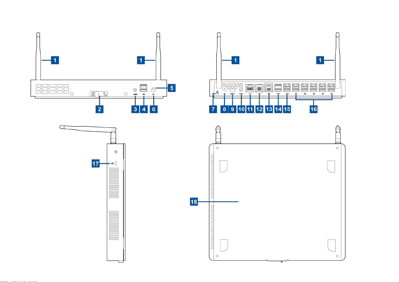
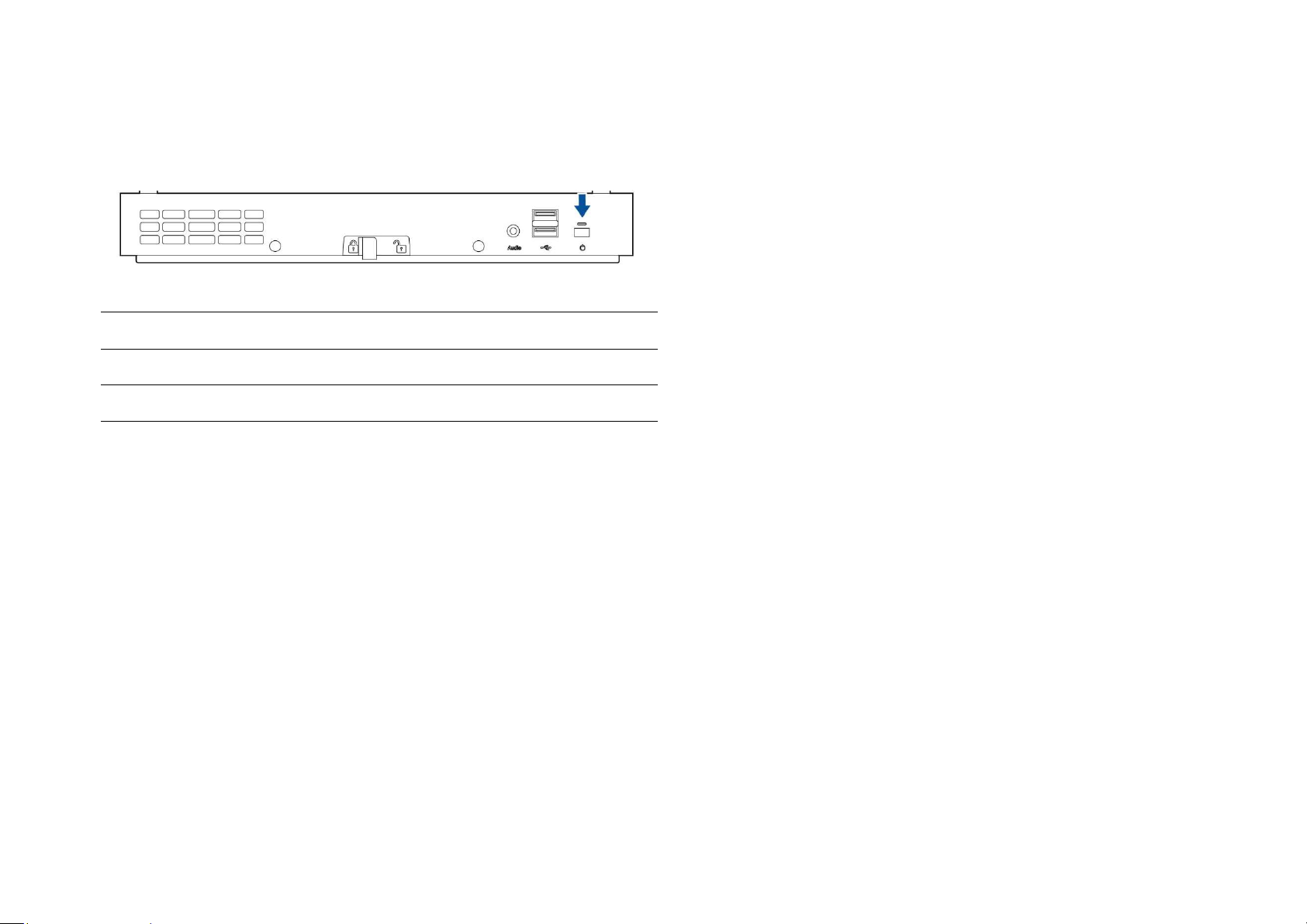
1 Wifi Antenna 10 HDMI Port
2 Mounting Bracket Release Latch 11 Serial Port (COM/RJ-50)
3 Headset 12 Cash Drawer Port (A/B)
4 USB 3.0 Port (0.9A) 13 Ethernet LAN Port
5 Power Indicator LED 14 USB 3.0 Port (0.9A)
6 Power Button 15 +24 Volts Powered USB Port
7 Kensington Nano Lock 16 +12 Volts Powered USB Port
8 Power Connector (DC-IN) 17 Kensington Lock
9 USB Type-C Port 18 Mounting Bracket
1. Wifi Antenna
Attach the supplied antennae to the EloPOS Pack when Wifi is needed. The antenna is compatible with 2.4G and 5GHz bands.
2. Mounting Bracket Release Latch
Sliding the latch to the right will release the mounting bracket from the EloPOS Pack.
3. Headset
The audio port is designed for headset and microphone connectivity.
4. USB 3.0 Port (0.9A)
Two standard Super Speed USB 3.0 ports are available on the front panel of the EloPOS Pack.
5. Power Indicator LED
The power indicator LED shows the state of the EloPOS Pack. See Section 3 for more details.
6. Power Button
Press the power button to turn on/off the EloPOS Pack.
User Manual: EloPOS Pack
UM600363 Rev A, page 6 of 37
Page 7
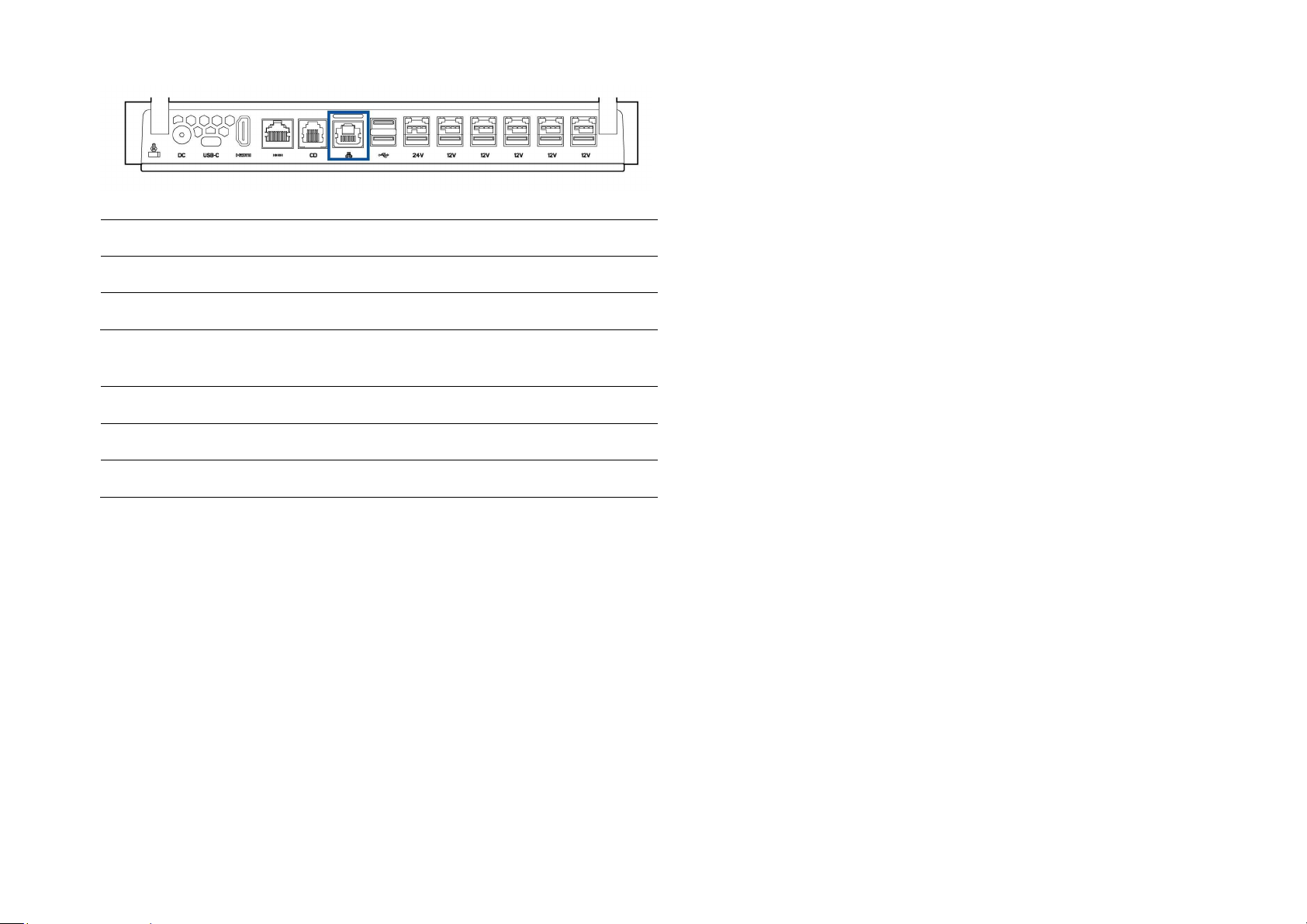
7. Kensington Nano Lock
Kensington Nano Lock is an ultra-slim sized anti-theft mechanism to secure the EloPOS Pack to the desired mounting location. The Kensington
cable lock is not included.
8. Power Connector (DC-IN)
To power up the EloPOS Pack, plug the DC connector of the AC/DC power adaptor kit into the power connection on the device.
9. USB Type-C Port
The USB Type-C port allows connection to other type-C compatible devices (Up to 27W).
10. HDMI Port
The HDMI port allows connection to a display equipped with HDMI input.
11. Serial Port (COM/RJ-50)
The serial port is a native RS-232 specification for RJ-50 interface connection.
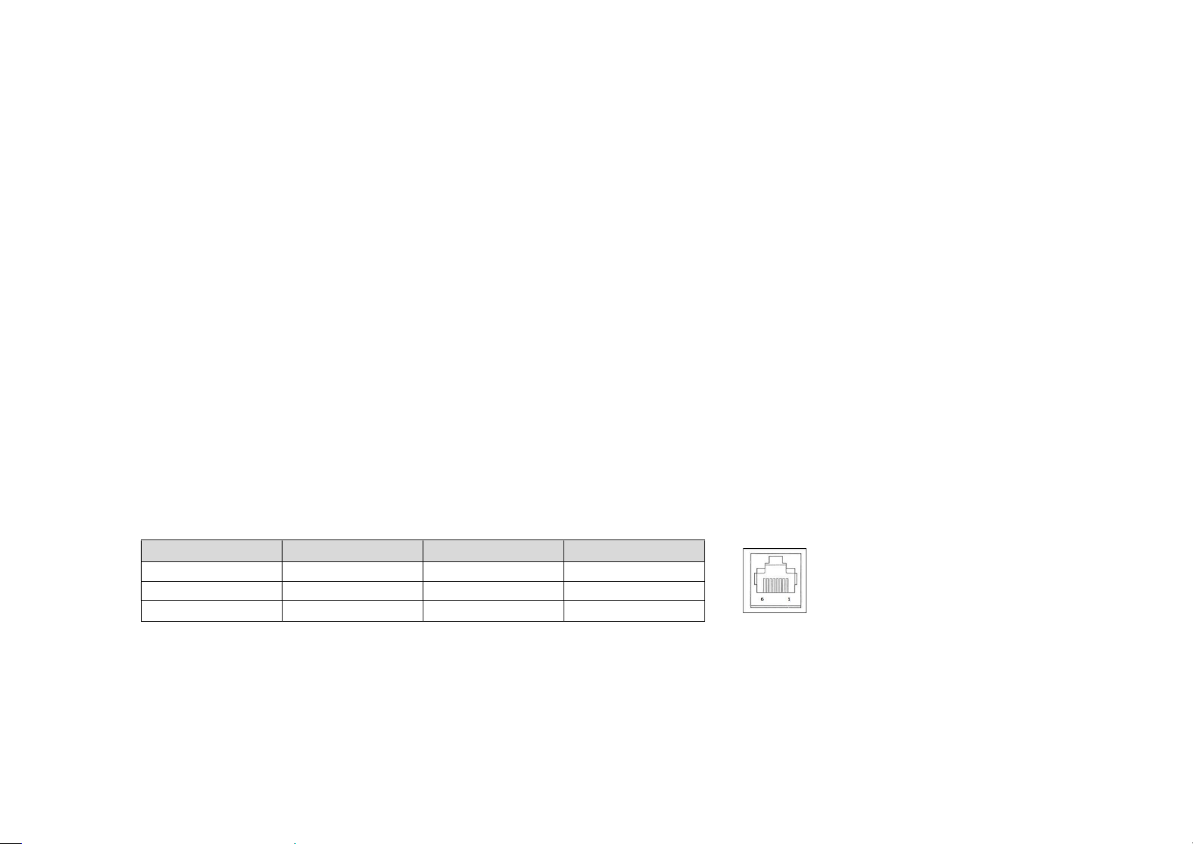
12. Cash Drawer Port (A/B)
The main cash drawer port is a RJ-12 interface and provides switchable operation at +12 Volts and +24 Volts. The default setting is at +24 Volts
and the settings are adjustable from the bottom of the EloPOS Pack.
a. Cash Drawer Port Pin assignment
Pin# Signal Name Pin# Signal Name
1 GND 2 CD13 CD1 Sense 4 CD Drive (+24/12V)
5 CD2- 6 Reserve
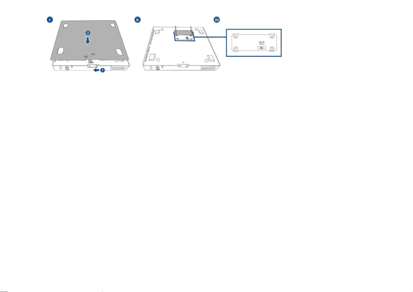
b. Switching between the +12 Volts and +24 Volts
i. Slide the latch to release mounting bracket from the EloPOS Pack, then slide the EloPOS Pack back to separate it from the bracket.
ii. Remove the cover from the bottom of the EloPOS Pack to reveal the switch.
iii. Slide the switch between 24V or 12V for the cash drawer power.
User Manual: EloPOS Pack
UM600363 Rev A, page 7 of 37
Page 8
13. Ethernet LAN Port
The Ethernet LAN Port provides up to 1 Gbps speed capability for networking.
14. USB 3.0 Port (0.9A)
Two standard Super Speed USB 3.0 ports are available on the rear side.
15. +24 Volts Powered USB Port
The +24 Volts Powered USB Port is included on all models. The maximum power rating of the +24 Volts Powered USB is 24 Volts at 0.5 Amps. If
your EloPOS Pack is running at 100% load and all I/O ports, except 24V Powered USB port are connected, at the maximum power load of each
port, DO NOT use the +24 Volts Powered USB port, use an external power adapter for the +24 Volts Powered peripheral.
Please ensure your overall peripheral power consumption does not exceed the following (assuming the EloPOS Pack is running at max power
consumption):
a. Do not exceed 145W for EPS00E2 models.
b. Do not exceed 130W for EPS00E3 models.
c. Do not exceed 124W for EPS00E5 models.
16. +12 Volts Powered USB Port
The maximum power rating of the +12 Volts Powered USB is 12 Volts at 1 Amps.
17. Kensington Lock
Kensington Lock is a standard anti-theft mechanism to secure the EloPOS Pack to the desired mounting location. The Kensington cable lock is
not included.
18. Mounting Bracket
The bracket has four holes to mount on a table by using four M4 or #8 mounting screws. The screw head height must be 3.0 mm (0.118”) or less.
When mounting on a wall, it is recommended using four M3 or #8 screws. The screw length must be longer than 25 mm, and the screw head
height must be 3.0 mm (0.118”) or less.
User Manual: EloPOS Pack
UM600363 Rev A, page 8 of 37
Page 9
User Manual: EloPOS Pack
Section 2: Installation
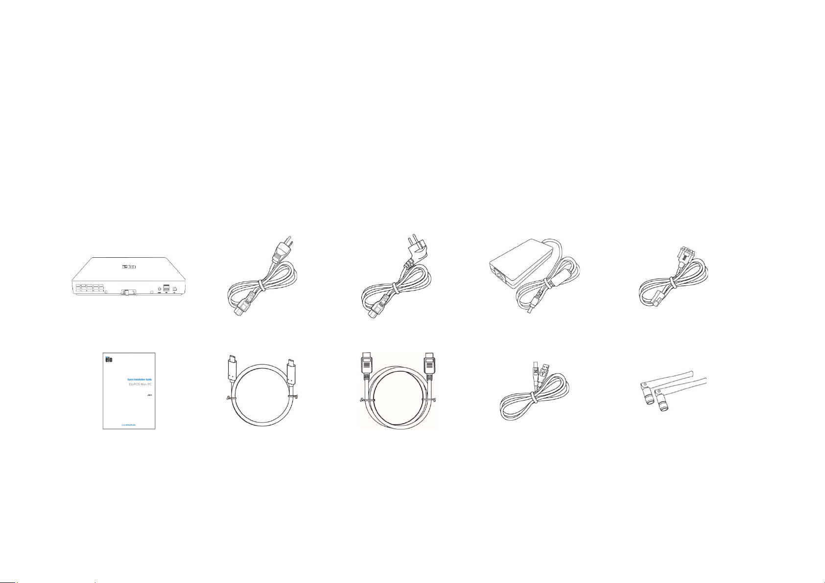
Unpacking the EloPOS Pack
Open the carton and verify that the following items are present:
EloPOS Pack
Power Cable US/Canada
Power Cable Europe
+24 Volts Power Adaptor
RJ50 to DB9 Serial Cable
EloPOS Pack
Quick Install Guide
USB Type-C Cable
HDMI Cable
USB Cable
SMA Antenna (2 pcs)
Power Cable US/Canada Power Cable Europe +24 Volts Power Adaptor RJ50 to DB9 Serial Cable
Quick Install Guide
USB Type-C Cable
HDMI Cable USB Cable SMA Antenna (2 pcs)
UM600363 Rev A, page 9 of 37
Page 10

Mounting the EloPOS Pack
The EloPOS Pack can be mounted with the supplied mounting bracket. Refer to the picture below to ensure it is installed in correct orientation.
User Manual: EloPOS Pack
UM600363 Rev A, page 10 of 37
Page 11
Section 3: Operation
Power LED
The EloPOS Pack has a Power LED indicating the state of the power. The table below shows LED state and corresponding color.
Status LED Light
AC off Off
Off mode Red
Sleep mode Orange
On Green
When the EloPOS Pack is connected to peripherals such as a touch screen, mouse, or keyboard, touching the screen, moving the mouse, or pressing
a keyboard key will bring the system out of SLEEP mode.
User Manual: EloPOS Pack
UM600363 Rev A, page 11 of 37
Page 12
Ethernet LAN LED
LAN Speed Status LAN LED Status
10 Mbps No Color
100 Mbps Orange Color
1 Gbps Green Color
Activity Status ACT LED Status
No Link No Color
Linked Solid (Green Color)
Data Activity Blinking (Green Color)
Setting Up the Operating System
To set up the operating system, you need to connect the EloPOS Pack to a display, plug in an external keyboard and/or mouse into its connector
panel to execute these steps
If the EloPOS Pack is configured with an operating system, the initial setup of the operating system takes approximately 5-10 minutes. Additional time
may be needed depending on the hardware configurations and connected devices.
To set up the Microsoft® Windows® Operating System for the EloPOS Pack, turn it on by pressing the power button, and then follow the on-screen
instructions.
Elo has taken time to ensure all drivers are correct and loaded for your Windows operating system. If you decide to create your own image, be sure
to start with the Elo image and Elo driver packs. Or contact our support team for help.
User Manual: EloPOS Pack
UM600363 Rev A, page 12 of 37
Page 13

Creating the Recovery Flash Drive
All Windows 10 models come with the built-in Elo Restore Utility on the Windows Desktop. The utility is able to create a recovery flash drive based on
the operating system you purchased. Please create your recovery flash drive immediately. In the event the HDD/SSD recovery partition is
accidentally deleted or becomes inaccessible, you will need to use the recovery flash drive to recover your system.
The following procedures demonstrate how to use the utility to create a recovery flash drive.
1. Right-click the EloRestoreUtility icon on the Desktop and select “Run as administrator”.
2. Click “Start” button to begin the process.
3. Once completed, you shall see a pop-up window to ask to insert a blank flash drive to any of available USB ports on your EloPOS Pack.
User Manual: EloPOS Pack
UM600363 Rev A, page 13 of 37
Page 14

4. After the flash drive is inserted, you shall see a window as shown below. Click “Format Drive” to continue the process. PLEASE NOTE THAT ALL
DATA WILL BE LOST DURING THIS PROCESS.
5. Click “Create Restore Media” to proceed. This step will take 10-20 minutes depending on the configurations and flash drive performance.
User Manual: EloPOS Pack
UM600363 Rev A, page 14 of 37
Page 15

6. Once the message shows "Creation Restore Media success...", please remove the flash drive and click "Exit" to exit the program.
7. In case the system crashed and you have to use the recovery flash drive, reboot the EloPOS Pack and press F11 several times to enter
DeviceBoot Menu. Then, choose “boot from flash drive”.
8. When the following User Interface (UI) is presented, click “Install Recovery Solution” button.
User Manual: EloPOS Pack
UM600363 Rev A, page 15 of 37
Page 16

9. Follow the on-screen instructions to complete the installation process and then exit the program.
Note: All data is deleted during the recovery process. The user must back up files when necessary. Elo Touch Solutions does not accept liability for
lost data or software.
Note: The end user must adhere to Microsoft's Licensing Agreement.
User Manual: EloPOS Pack
UM600363 Rev A, page 16 of 37
Page 17

Recovering the Operating System
If for any reason the operating system needs to be recovered to FACTORY SETTINGS, you can recover your system by following the procedures
below. PLEASE NOTE THAT ALL CUSTOMER SETTINGS AND DATA WILL BE LOST DURING THIS PROCESS. Please be sure to completely backup all of your
data, settings, and customer-installed software before proceeding.
1. Power off your EloPOS Pack completely.
2. Power on your EloPOS Pack.
3. When the following screen appears, tap to select “UEFI – Recover Operating System”.
User Manual: EloPOS Pack
UM600363 Rev A, page 17 of 37
Page 18

4. The following User Interface (UI) will be presented.
5. Select Restore OS. The system will test your hardware automatically. Once the process completes, click Start button to perform the system
recovery function.
User Manual: EloPOS Pack
UM600363 Rev A, page 18 of 37
Page 19

User Manual: EloPOS Pack
6. The following process will reformat the primary hard drive. Please back up your data before performing the recovery process.
7. Once completed, click the Close button. The system will return to the main menu of the Elo Recovery Solution. Then click the Exit button to
restart your system.
NOTE: All data is deleted during the recovery process. The user must back up files when necessary. Elo Touch Solutions does not accept liability
for lost data or software.
NOTE: The end user must adhere to Microsoft's Licensing Agreement.
UM600363 Rev A, page 19 of 37
Page 20

Section 4: Options and Upgrades
Adding Optional Upgrades
Elo has qualified the following to work seamlessly with your unit. The complete installation and setup instructions are provided with the fieldinstallable kits. Please see your Elo authorized distributor or value-added partner for pricing.
KIT, 2ND DDR4 SODIMM, 4GB 2666MHZ (E264186)
KIT, 2ND DDR4 SODIMM, 8GB 2666MHZ (E264375)
KIT, 2ND DDR4 SODIMM, 16GB 2666MHZ (E263989)
KIT, 2ND SSD, M.2 SATA 128GB (E206352)
KIT, 2ND SSD, M.2 SATA 256GB (E206556)
User Manual: EloPOS Pack
UM600363 Rev A, page 20 of 37
Page 21

Section 5: Technical Support
er button
If you are experiencing trouble with your EloPOS Pack, refer to the following suggestions. If the problem persists, please contact your local
dealer or Elo Customer Service. Worldwide technical support phone numbers are available on the last page of this user manual.
Solutions to Common Problems
Problem Suggested Troubleshooting
1. Check that the AC/DC power adaptor is properly connected.
The unit won’t power up.
Monitor connected to the EloPOS
Pack has a blank screen.
No Bootable Device Found
Technical Assistance
Technical Specifications
Visit www.elotouch.com/products
for technical specifications for this device
2. Verify the AC power source is functioning.
3. Make sure the power button is not broken.
1. If the Power Status LED is orange/red, the unit may be in SLEEP/HIBERNATE mode. Press the pow
to see if the display comes back.
2. Check the internal cable connections and look for missing or damaged electrical components.
1. Confirm the product has loaded the OS.
2. Storage device damage - Try to swap with another new blank drive.
Support
Visit https://www.elotouch.com/support/technical-support
for technical support
See this user manual's last page for worldwide technical support phone numbers.
User Manual: EloPOS Pack
UM600363 Rev A, page 21 of 37
Page 22

Section 6: Safety & Maintenance
Safety
To avoid risk of electric shock, follow all safety notices and do not disassemble the EloPOS Pack. They are not user-serviceable.
Do not block or insert anything inside the ventilation slots.
The EloPOS Pack is equipped with an AC/DC power adaptor. Do not use a damaged AC/DC power adaptor. Use only the AC/DC power
adaptor supplied by Elo. Use of an unauthorized AC/DC power adaptor may void your warranty.
Ensure that the EloPOS Pack is maintained and runs within the specified environmental conditions listed below.
Be sure to disconnect the power source before disassemble cover from the bottom of the EloPOSPack to reveal the switch. The cover from the
bottom must be completely assembled while restoring the power input. Wait one-half hour after switching off before handling parts.
Environmental conditions for operating and storage
Temperature:
Operating 0°C to 40°C
Storage -20°C to 60°C
Humidity (non-condensing):
Operating 10% to 90%
Storage 0% to 95%
Altitude:
Operating 0 to 3,048 m
Storage 0 to 12,192 m
Power ratings
24 Volts, 7.5 Amps max
User Manual: EloPOS Pack
UM600363 Rev A, page 22 of 37
Page 23

Power Adaptor Support Notice
The following information will help with management of power supply and usage on your EloPOS Pack.
The +24 Volts 180W power adaptor (E511572/E511766) can’t support all full I/O port specs at the same time; it will limited to configuration by +12
Power USB (5 Ports/1A) and +24 Power USB (1 Port/0.5A), unless great care is taken to check the total wattage of the system.
Do not exceed a total of 180 watts. Take the wattage below and add the Elo Peripherals or your other devices and check that you are under 180
watts. If you need help with the power requirements for your application, please contact Elo support to help you with the set up and
calculations.
The Elo PNs corresponding power adaptor model name list as below table.
Configuration ELO PN Part Description
EPS00E2/EPS00E3/EPS00E5
E511572 AIO POWER BRICK, 24VOLT 180W, DELTA
Care and Handling
The following tips will help keep your EloPOS Pack functioning at an optimal level:
Disconnect the AC power cable before cleaning.
To clean the unit, use a clean cloth lightly dampened with a mild detergent.
It is important that your unit remains dry. Do not get liquids on or inside the unit. If liquid does get inside, turn the unit off and have a qualified
service technician checks it before you power it on again
Ensure the environmental temperature and humidity are maintained within specification and do not block ventilation slots.
The unit is not designed for the outdoors.
User Manual: EloPOS Pack
UM600363 Rev A, page 23 of 37
Page 24

User Manual: EloPOS Pack
Waste Electrical & Electronic Equipment Directive (WEEE)
This product should not be disposed of with household waste. It should be deposited at a facility that enables recovery and recycling. Ensure
that product is disposed at the end of its useful life according to local laws and regulations. Elo has put in place recycling arrangements in
certain parts of the world. For information on how you can access these arrangements, please visit.
https://www.elotouch.com/e-waste-recycling-program
UL Directive
The EloPOS Pack has a lithium battery included on the motherboard. There is a risk of explosion if battery is replaced by an incorrect type. Please
dispose of used batteries according the region instructions.
Warning
It is important that your EloPOS Pack remains dry, do not pour liquid into or onto it. If it becomes wet, do not attempt to repair it yourself. Contact
Elo Customer Service for instructions.
UM600363 Rev A, page 24 of 37
Page 25

Section 7: Regulatory Information
Electrical Safety Information
Compliance is required with respect to the voltage, frequency, and current requirements indicated on
the manufacturer's label. Connection to a different power source than those specified herein will likely
result in improper operation, damage to the equipment or pose a fire hazard if the limitations are not
followed.
There are no operator serviceable parts inside this equipment. There are hazardous voltages generated
by this equipment which constitute a safety hazard. Service shall be provided only by a qualified service
technician.
Contact a qualified electrician or the manufacturer if there are questions about the installation prior to
connecting the equipment to mains power.
Emissions and Immunity Information
Notice to Users in the United States for FCC compliance:
This device complies with part 15 of the FCC Rules. Operation is subject to the following two conditions:
(1) This device may not cause harmful interference, and (2) this device must accept any interference
received, including interference that may cause undesired operation of the device.
Changes or modifications not expressly approved by the party responsible for compliance could void
the user‘s authority to operate the equipment.
NOTE: This equipment has been tested and found to comply with the limits for a Class B digital device,
pursuant to part 15 of the FCC Rules. These limits are designed to provide reasonable protection against
harmful interference in a residential installation. This equipment generates, uses and can radiate radio
frequency energy and, if not installed and used in accordance with the instructions, may cause harmful
interference to radio communications. However, there is no guarantee that interference will not occur
in a particular installation. If this equipment does cause harmful interference to radio or television
reception, which can be determined by turning the equipment off and on, the user is encouraged to
try to correct the interference by one or more of the following measures:
—Reorient or relocate the receiving antenna.
User Manual: EloPOS Pack
UM600363 Rev A, page 25 of 37
Page 26

—Increase the separation between the equipment and receiver.
—Connect the equipment into an outlet on a circuit different from that to which the receiver is
connected.
—Consult the dealer or an experienced radio/TV technician for help.
This equipment should be installed and operated to ensure a minimum of 20 cm spacing to any person.
Notice to Users in Canada for IC compliance:
This equipment complies with the Class B limits for radio noise emissions from digital apparatus as established
by the Radio Interference Regulations of Industrial Canada.
CAN ICES3 (B)/NMB3(B)
This device contains license-exempt transmitter(s)/receiver(s) that comply with Innovation, Science and
Economic Development Canada’s license-exempt RSS(s). Operation is subject to the following two
conditions:
1. This device may not cause interference.
2. This device must accept any interference, including interference that may cause undesired
operation of the device.
L’émetteur/récepteur exempt de licence contenu dans le présent appareil est conforme aux CNR
d’Innovation, Sciences et Développement économique Canada applicables aux appareils radio exempts
de licence. L’exploitation est autorisée aux deux conditions suivantes:
1. L’appareil ne doit pas produire de brouillage;
2. L’appareil doit accepter tout brouillage radioélectrique subi, même si le brouillage est susceptible
d’en compromettre le fonctionnement.
Notice to Users in the European Union:
Use only the provided power cords and interconnecting cabling provided with the equipment.
Substitution of provided cords and cabling may compromise electrical safety or CE Mark Certification
for emissions or immunity as required by the following standards:
This Information Technology Equipment (ITE) is required to have a CE Mark on the Manufacturer’s label
which means that the equipment has been tested to the following Directives and Standards: This
equipment has been tested to the requirements for the CE Mark as required by EMC Directive 2014/30/
User Manual: EloPOS Pack
UM600363 Rev A, page 26 of 37
Page 27

EU as indicated in European Standard EN 55032 Class B and the Low Voltage Directive 2014/35/EU as
indicated in European Standard EN 60950-1.
Classification of Certificate
Series Configuration Classification
Documentation
EloPOS Pack
EPS00E2/EPS00E3/EPS00E5
Class B MD600104 DECLARATIONS OF CONFORMITY, EloPOS Pack
Radio Equipment Directive
Elo hereby declares that the radio equipment type, EloPOS Pack, is in compliance with Directive
2014/53/EU. The full text of the EU Declaration of Conformity is available at the following internet
address: www.elotouch.com
This device is designed and intended for indoor use only.
AT BE BG HR CY CZ DK
EE FI FR DE EL HU IE
IT LV LT LU MT NL PL
PT RO SK SI ES SE UK
Operation frequency and radio-frequency power are listed as below:
o WLAN 802.11a/b/g/n/ac 2400MHz ≤ 20 dBm EIRP
5150 – 5250MHz ≤ 23 dBm EIRP
o Bluetooth 2.4GHz ≤ 9.5 dBm
User Manual: EloPOS Pack
UM600363 Rev A, page 27 of 37
Page 28

ECC/DEC/ (04)08:
The use of the frequency band 5 150-5 350 MHz is restricted to indoor operation because of the
protection requirements of satellite services
EC R&TTE Directive
EU Directive 2014/53/EU of the European Parliament and of the Council of 16 April 2014 on the
harmonization of the laws of the Member States relating to the making available on the market of
radio equipment and repealing Directive 1999/5/EC Text with EEA relevance.
Identification mark
The relevant technical documentation is held at: Elo Touch Solutions, Inc.
670 N. McCarthy Boulevard Suite 100
Milpitas, CA 95035
USA.
USA
FCC ID: PD99260NG
Canada
IC ID: 1000M-9260NG
Japan
RF 003‐170125
TEL D170079003
Argentina
CNC: C-20821
Brazil
Anatel: 05831-17-04423
Este equipamento não tem direito à proteção contra interferência prejudicial e não pode causar interferência em sistemas devidamente
autorizados.
User Manual: EloPOS Pack
UM600363 Rev A, page 28 of 37
Page 29

Mexico
WLAN Module installed inside this computer
IFETEL Certification number: RCPIN9517-1585
Brand name of the approved module: Intel
Model name of the approved module: 9260NGW
Información México La operación de este equipo está sujeta a las siguientes dos condiciones:
1) es posible que este equipo o dispositivo no cause interferencia perjudicial y
2) este equipo debe aceptar cualquier interferencia, incluyendo la que pueda causar su operación no deseada.
RF Exposure Information (SAR)
This device has been tested and meets applicable limits for Radio Frequency (RF) exposure. Specific Absorption Rate (SAR) refers to the rate at
which the body absorbs RF energy. Tests for SAR are conducted using standard operating positions with the device transmitting at its highest
certified power level in all tested frequency bands. This device was tested with a separation distance of 20cm. Always keep this device away from
your body to ensure exposure levels remain at or below the as-tested levels.
General Information to all Users:
This equipment generates, uses and can radiate radio frequency energy. If not installed and used
according to this manual the equipment may cause interference with radio and television
communications. There is, however, no guarantee that interference will not occur in any particular
installation due to site-specific factors.
1. In order to meet emission and immunity requirements, the user must observe the following:
a. Use only the provided I/O cables to connect this digital device with any computer.
b. To ensure compliance, use only the provided manufacturer’s approved line cord.
c. The user is cautioned that changes or modifications to the equipment not expressly approved
by the party responsible for compliance could void the user’s authority to operate the
equipment.
2. If this equipment appears to cause interference with radio or television reception, or any other device:
a. Verify as an emission source by turning the equipment off and on. If you determine that this
equipment is causing the interference, try to correct the interference by using one or more of
the following measures:
i. Move the digital device away from the affected receiver.
ii. Reposition (turn) the digital device with respect to the affected receiver.
iii. Reorient the affected receiver’s antenna.
iv. Plug the digital device into a different AC outlet so the digital device and the receiver
are on different branch circuits.
User Manual: EloPOS Pack
UM600363 Rev A, page 29 of 37
Page 30

v. Disconnect and remove any I/O cables that the digital device does not use.
(Unterminated I/O cables are a potential source of high RF emission levels.)
vi. Plug the digital device into only a grounded outlet receptacle. Do not use AC
adapter plugs. (Removing or cutting the line cord ground may increase RF emission
levels and may also present a lethal shock hazard to the user.)
If you need additional help, consult your dealer, manufacturer, or an experienced radio or television
technician.
User Manual: EloPOS Pack
UM600363 Rev A, page 30 of 37
Page 31

User Manual: EloPOS Pack
UM600363 Rev A, page 31 of 37
Page 32

Agency Certifications
The following certifications and marks have been issued or declared for this system:
United State FCC, UL , Energy Star®
Canada IC
Europe CE, CB
Australia RCM
Japan VCCI
Argentina S-Mark
Brazil, ANATEL
China CCC, SRRC
Mexico NOM
User Manual: EloPOS Pack
UM600363 Rev A, page 32 of 37
Page 33

Explanation of Markings
1. In accordance with the SJ/T11364-2006 requirement, the electronic information products are marked with the following pollution control
logo. The Environment-Friendly Use Period for this product is 10 years. The product will not leak or mutate under normal operating
conditions listed below, so that the use of this electronic information product will not result in any severe environmental pollution, any bodily
injury, or damage to any assets.
Operating Temperature: 0-35 / Humidity: 20%-80% (non-condensing).
Storage Temperature: -20~60 / umidity:10%~95% (non-condensing).
2. It is encouraged and recommended that this product be recycled and reused according to local laws. The product should not be
thrown away casually.
China RoHS
In accordance to Chinese law (Management Methods for the Restriction of the Use of Hazardous Substances in Electrical and
Electronic Products), the section below lists out the name and amount of the toxic and/or hazardous materials that this product may
contain.
Component Name Toxic or Hazardous Substances and Elements
Lead (Pb) Mercury (Hg) Cadmium (Cd)
Plastic Parts O O O O O O
Metal Parts X O O O O O
Wire and Cable
PCBA X O O O O O
X O O O O O
Hexavalent
Chromium (Cr6+)
Polybrominated
Biphenyls (PBB)
Polybrominated Diphenyl
Ethers (PBDE)
User Manual: EloPOS Pack
UM600363 Rev A, page 33 of 37
Page 34

中国 RoHS (China RoHS)
(Cr6+)
(PBB)
(PBDE)
根据中国法律《电器电子产品有害物质限制使用管理办法》,以下部分列出了产品中可能包含的有害物质的名称和含量。
中国电子电气产品环境信息
有毒或有害物质与元素
部件名称
铅 (Pb) 汞 (Hg) 镉 (Cd) 六价铬
多溴联苯
多溴联苯醚
塑料部件
O O O O O O
金属零件 X O O O O O
电线和电缆
组件
印制线路板
X O O O O O
X O O O O O
本表格依据 SJ/T 11364 的规定编制.
〇: 表示该有害物质在该部件所有均质材料中的含量均在 GB/T 26572 规定的限量要求以下.
X: 表示该有害物质至少在该部件的某一均质材料中的含量超出GB/T 26572规定的限量要求.对于带X的项
目,已经根据欧洲RoHS认证豁免。
标志说明
(1) 根据 SJ/T 11364 的要求,电子信息产品标有以下污染控制标识。 此产品在 10 年内不会对环境产生影响。
(2) 绿色产品标识
User Manual: EloPOS Pack
UM600363 Rev A, page 34 of 37
Page 35

Section 8: Warranty Information
For warranty information, go online to https://www.elotouch.com/support/warranty
User Manual: EloPOS Pack
UM600363 Rev A, page 35 of 37
Page 36

Notes
______________________________________________________________________________________________________________________
______________________________________________________________________________________________________________________
______________________________________________________________________________________________________________________
______________________________________________________________________________________________________________________
______________________________________________________________________________________________________________________
______________________________________________________________________________________________________________________
______________________________________________________________________________________________________________________
______________________________________________________________________________________________________________________
______________________________________________________________________________________________________________________
______________________________________________________________________________________________________________________
______________________________________________________________________________________________________________________
______________________________________________________________________________________________________________________
______________________________________________________________________________________________________________________
______________________________________________________________________________________________________________________
______________________________________________________________________________________________________________________
______________________________________________________________________________________________________________________
______________________________________________________________________________________________________________________
______________________________________________________________________________________________________________________
______________________________________________________________________________________________________________________
User Manual: EloPOS Pack
UM600363 Rev A, page 36 of 37
Page 37

www.elotouch.com
Visit our website for the latest
Product Information
Specifications
Upcoming Events
Press Releases
Software Drivers
Touch Monitor Newsletter
To find out more about our extensive range of Elo touch solutions, go to www.elotouch.com, or call the office nearest you.
North America
Tel +1 408 597 8000
Fax +1 408 597 8001
elosales.na@elotouch.com
Europe
Tel +32 (0)16 70 45 00
Fax +32 (0)16 70 45 49
elosales@elotouch.com
Asia-Pacific
Tel +86 (21) 3329 1385
Fax +86 (21) 3329 1400
www.elotouch.com.cn
Latin America
Tel +52 55 2281-6958
elosales.latam@elotouch.com
© 2019 Elo Touch Solutions, Inc. All rights reserved.
 Loading...