

Page 1

www.elotouch.com
Installation Guide
Wall Mount Kit for
Elo 3202/4202/4602 IDS Monitors
Revision A
P/N UM600076
Page 2

© 2016 Elo Touch Solutions, Inc. All rights reserved.
Elo Touch Solutions Technical Support
Online self-help: www.elotouch.com/go/websupport
Technical Support contacts in your region:
www.elotouch.com/go/contactsupport
The information in this document is subject to change without notice. Elo Touch Solutions, Inc. and its Afliates (collectively
“Elo”) makes no representations or warranties with respect to the contents herein, and specically disclaims any implied
warranties of merchantability or tness for a particular purpose. Elo reserves the right to revise this publication and to
make changes from time to time in the content hereof without obligation of Elo to notify any person of such revisions or
changes.
No part of this publication may be reproduced, transmitted, transcribed, stored in a retrieval system, or translated into
any language or computer language, in any form or by any means, including, but not limited to, electronic, magnetic,
optical, chemical, manual, or otherwise without prior written permission of Elo Touch Solutions, Inc.
Elo (logo) and Elo Touch Solutions are trademarks of Elo and its Afliates.
North America
Elo Touch Solutions
1033 McCarthy Boulevard
Milpitas, CA 95035
800-ELO-TOUCH
Tel +1 408 597 8000
Fax +1 408 597 8050
customerservice@elotouch.com
Europe
Tel +32 (0)16 70 45 00
Fax +32 (0)16 70 45 49
elosales@elotouch.com
Asia-Pacic
Tel +86 (21) 3329 1385
Fax +86 (21) 3329 1400
www.elotouch.com.cn
Latin America
Tel 786-923-0251
Fax 305-931-0124
www.elotouch.com
Safety Warning:
Do not install this equipment on any wall or structure that is not capable of supporting four times
the weight of the IDS Display, brackets, and any accessories attached to it.
The 3202L monitor weighs in excess of 37lbs (17kg) with the optional Elo computer module.
37lbs x 4 = 148lbs (68kg).
The 4202L monitor weighs in excess of 55lbs (25kg) with the optional Elo computer module.
55lbs x 4 = 220lbs (100kg).
The 4602L monitor weighs in excess of 60lbs (27kg) with the optional Elo computer module.
60lbs x 4 = 240lbs (108kg).
Do not leave out any required parts or leave the monitor on the wall unattended without securely
fastening all brackets and screws as instructed in this document. Failure to follow all installation
instructions can result in an unsafe installation. Serious injury can occur if the IDS Display unexpectedly falls due to improper installation.
Caution: This wall mount is intended for use only with the maximum weights indicated. Use with
heavier than the maximum weights indicated may allow the IDS Display to fall and cause injury.
Page 3
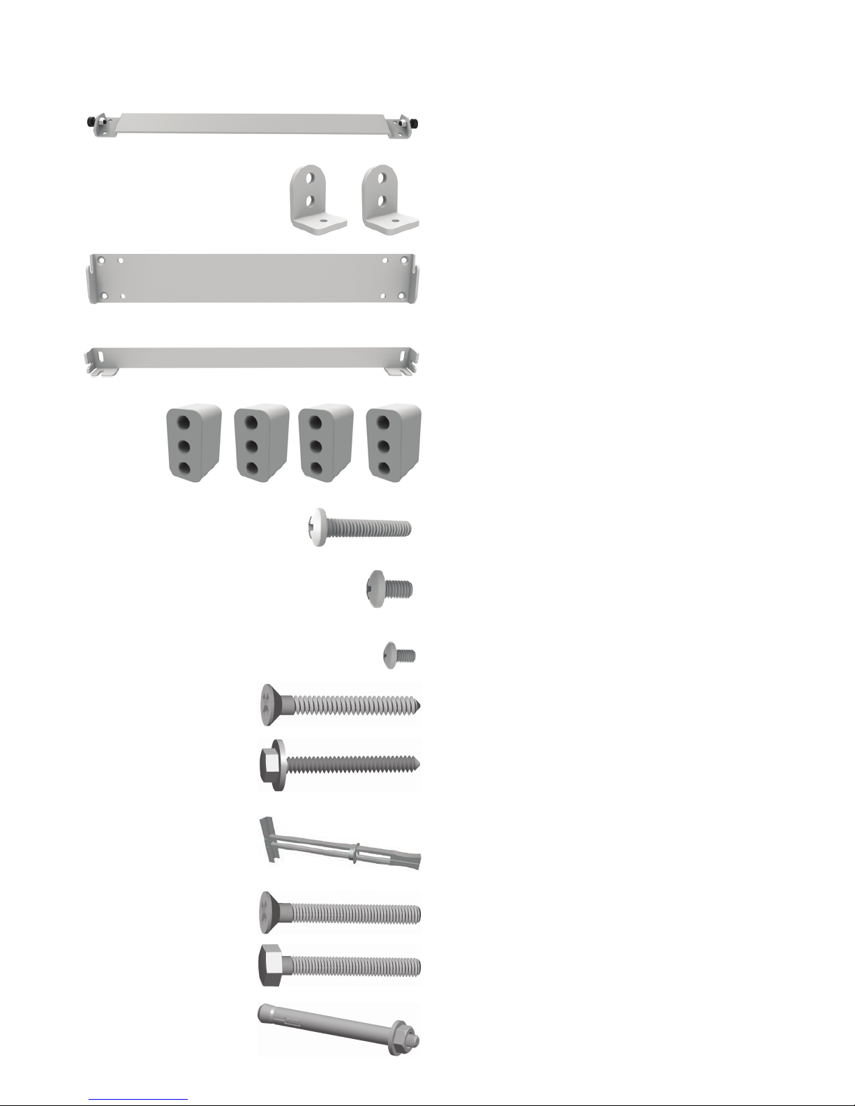
Kit Contents
(Landscape and portrait installation templates, dimensional drawings, and the below hardware)
Upper Wall Bracket, (x1)
Lower Wall Bracket, (x1)
ECM Spacer, (x4)
M6X34 Phillips head screw (x8)
For IDS with ECM
M6X8 Phillips head screw (x8)
For IDS without ECM
1/4” x 2-1/2” at head wood screw (x6)
1/4” x 1-/2” hex head wood screw (x6)
1/4” Heavy Duty Toggle Anchor (x6)
(Additional anchors available P/N Toggler 25014)
1/4-20 x 2-1/2” at head machine screw (x4)
1/4-20 x 2-1/2” hex head machine screw (x2)
5/16” x 2-1/2” Concrete Sleeve Anchor (x6)
Minimum pullout strength rating = 1500lbs
M4X10 Phillips head screw (x2)
Lower Display Bracket, (x2)
Upper Display Bracket, (x1)
Page 4
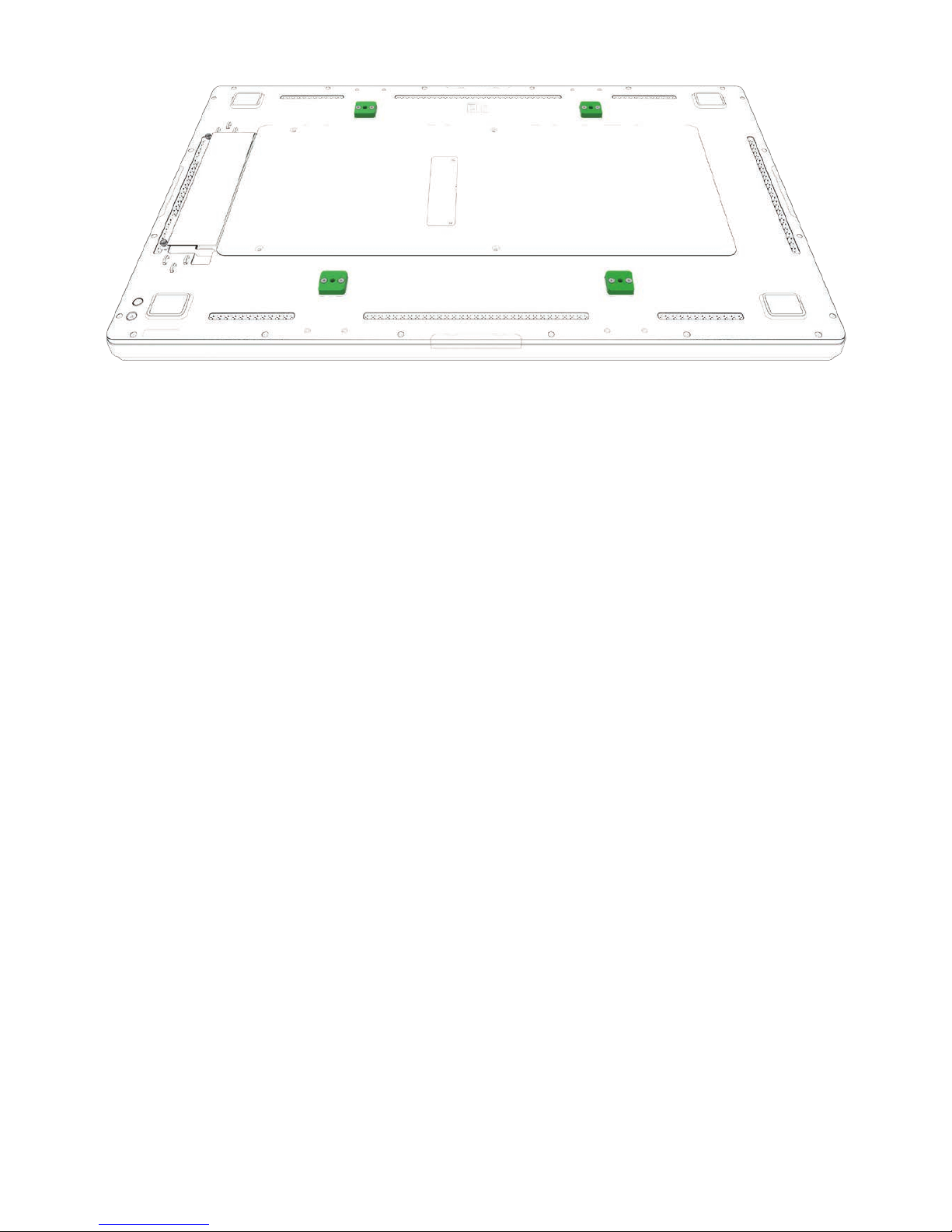
Step 1:
Remove the four (4) VESA mount covers to expose the wall mount bracket mounting pads. These
covers are not reused with this wall mount kit.
Step 2:
For mounting an IDS in landscape orientation, go to step 3a.
For mounting an IDS in portrait orientation, go to step 3b.
For mounting an IDS with ECM in landscape orientation, install the ECM kit following instructions
provided with it and go to step 3c.
For mounting an IDS with ECM in portrait orientation, install the ECM kit following instructions provided with it and go to step 3d.
Page 5

Step 3a: Attach upper and lower display brackets (Landscape orientation)
• Secure the upper display bracket to the upper mounting pads using four M6x8 screws.
• Secure each of the lower display brackets to the other two mounting pads using two M6x8
screws. Ensure the lower brackets are installed according to notes 1-2 below.
• Proceed to step 4.
Upper Display Bracket
Lower Display Bracket
Mounting Pads
I/O Connections
The lower display brackets must be installed using the upper two
mounting holes on the mounting pad.
Loosely install an M4 screw
into each of the lower brackets as shown. The head of the
M4 screw should have at least
5mm (1/4”) of space under it.
1/4” (5mm)
Note 1
Note 2
Page 6

The lower display brackets must be installed using the center
mounting hole of the mounting pad and the left/right mounting
hole.
Upper Display Bracket
I/O Connections must point towards
the oor when wall mounted
Step 3b: Attach upper and lower display brackets (Portrait orientation)
• Secure the upper display bracket to the upper mounting pads using four M6x8 screws.
• Secure each of the lower display brackets to the other two mounting pads using two M6x8
screws. Ensure the lower brackets are installed according to notes 3-4 below.
• Proceed to step 4.
Loosely install an M4 screw into
each lower bracket as shown.
Leave about 5mm (1/4”) of
space under the head. The M4
screw on the left bracket should
point left and the M4 screw on
the lower right bracket should
point right.
Note 3 Note 4
Mounting pads
1/4” (5mm)
Lower Display Bracket
Page 7

Note 5 Note 6
Step 3c: Attach upper and lower display brackets (Landscape orientation with ECM)
• Secure the upper display bracket to the upper mounting pads using two ECM spacers and four
M6x34 screws.
• Secure lower display brackets to the other two mounting pads using one ECM spacer and two
M6x34 screws. Ensure lower brackets are installed according to notes 5-6 below.
• Proceed to step 4.
Upper Display Bracket
Mounting pads with
ECM spacers
I/O Connections
The lower display brackets must be installed using the upper two
mounting holes on the mounting pad.
Loosely install an M4 screw
into each of the lower brackets as shown. The head of the
M4 screw should have at least
5mm (1/4”) of space under it.
1/4” (5mm)
Lower Display Bracket
Page 8

The lower display brackets must be installed using the center
mounting hole of the mounting pad and the left/right mounting
hole.
Upper Display Bracket
I/O Connections must point towards
the oor when wall mounted
Step 3d: Attach upper and lower display brackets (Portrait orientation with ECM)
• Secure the upper display bracket to the upper mounting pads using two ECM spacers and four
M6x34 screws.
• Secure lower display brackets to the other two mounting pads using one ECM spacer and two
M6x34 screws. Ensure the lower brackets are installed according to notes 7-8 below.
• Proceed to step 4.
Note 7 Note 8
Mounting pads with
ECM spacers
1/4” (5mm)
Loosely install an M4 screw into
each lower bracket as shown.
Leave about 5mm (1/4”) of
space under the head. The m4
screw on the left bracket should
point left and the M4 screw on
the lower right bracket should
point right.
Lower Display Bracket
Page 9

Step 4: Attach upper and lower wall brackets (All congurations)
• The upper wall bracket must be secured with four 1/4” or M6 screws.
• The lower wall bracket must be secured with two 1/4” or M6 screws.
• The wall mount kit includes screws for wood and metal stud walls, concrete, and solid wood.
Both brackets must be mounted to structurally sound parts of the wall. Do not install on drywall without proper structure behind it. Installer must follow all applicable building codes when
installing this kit. Install all anchors and fasteners according to manufacturers instructions.
• Reference the installation template and included dimensional drawings for detailed dimensions
and mounting hole placement.
Flat head
screws only
Flat head
screws only
Hex head
screws only
Hex head
screws only
Hex head
screws only
Hex head
screws only
16.0”
(406.4mm)
13.98”
(355.0mm)
13.23”
(336.0 mm)
Page 10

Step 5: Attach IDS Display to wall brackets (all congurations)
• Elo recommends at least two people lift the IDS display onto the wall mount brackets.
• Tilt the monitor slightly back while lifting it onto the upper wall bracket. Ensure both pivot
screws on the upper monitor bracket are engaged in the hooks on the upper wall bracket. You
should be able to pivot the IDS Display forward a few inches when correctly installed.
• As the IDS Display pivots back against the wall, ensure both M4 screws installed on the lower
monitor brackets engages the slots on the lower wall bracket. If the M4 screws do not engage
the slots on the lower wall bracket, adjust the height of the lower wall bracket as needed to allow the screws to engage the slots.
Page 11

Step 6: Secure IDS Display to lower wall bracket (all congurations)
• Use a long Phillips head screw driver to tighten the M4 screws from the bottom side of the IDS
display when mounted in landscape orientation. (Portrait mounted IDS Displays require access
from the left and right side)
Tighten both screws to secure
the IDS Display
Page 12

Removing the IDS Display from the wall bracket (all congurations)
• Use a long Phillips head screw driver to loosen the M4 screws from the bottom side of the IDS
display when mounted in landscape orientation. (Portrait mounted IDS Displays require access
from the left and right side)
• Tilt the bottom of the IDS Display forward a few inches while lifting up and off the wall bracket.
Loosen both screws to remove
the IDS Display
 Loading...