

Page 1
www.elotouch.com
© 2016 Elo Touch Solutions, Inc. All rights reserved.
Elo Touch Solutions Technical Support
Online self-help: www.elotouch.com/go/websupport
Technical Support contacts in your region:
www.elotouch.com/go/contactsupport
The information in this document is subject to change without notice. Elo Touch Solutions, Inc. and its Afliates (collectively “Elo”) makes
no representations or warranties with respect to the contents herein, and specically disclaims any implied warranties of merchantability or
tness for a particular purpose. Elo reserves the right to revise this publication and to make changes from time to time in the content hereof
without obligation of Elo to notify any person of such revisions or changes.
No part of this publication may be reproduced, transmitted, transcribed, stored in a retrieval system, or translated into any language or
computer language, in any form or by any means, including, but not limited to, electronic, magnetic, optical, chemical, manual, or otherwise
without prior written permission of Elo Touch Solutions, Inc.
Elo (logo) and Elo Touch Solutions are trademarks of Elo and its Afliates.
North America
Elo Touch Solutions
1033 McCarthy Boulevard
Milpitas, CA 95035
800-ELO-TOUCH
Tel +1 408 597 8000
Fax +1 408 597 8050
customerservice@elotouch.com
Europe
Tel +32 (0)16 70 45 00
Fax +32 (0)16 70 45 49
elosales@elotouch.com
Asia-Pacic
Tel +86 (21) 3329 1385
Fax +86 (21) 3329 1400
www.elotouch.com.cn
Latin America
Tel 786-923-0251
Fax 305-931-0124
www.elotouch.com
Quick Installation Guide
Elo Expansion Module
Compatible with following products:
E021201 (15” I-Series Android)
E021388 (22” I-Series Android)
Revision A
P/N E231725
*E231725 REV.A*
Page 2
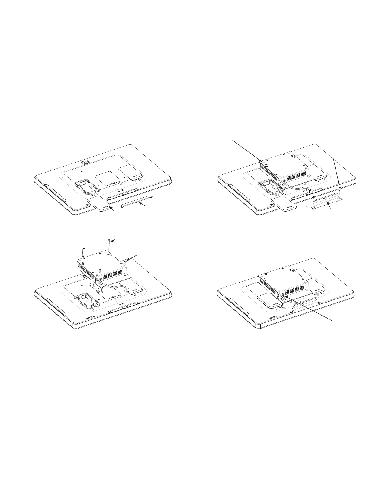
M4X32mm LONG,
QTY. 2
M4X7mm LONG,
QTY. 2
M3X8mm LONG,
QTY. 2
100x100mm M4 thread
VESA mount on back of expansion module
1. Remove DC power cover (D) and bottom peripheral cover (E). 3. Assemble micro-USB bracket using screws (C).
2. Assemble expansion module to VESA mount on back of i-Series using screws (A) and
(B). Connect the DC power and micro-USB connections as shown.
4. Connect power supply provided with expansion module to the DC jack on expansion module. Continue installation of i-Series Display as desired using stands and mounts available at
www.elotouch.com.
D
E
B
A
C
Micro-USB Bracket
DC Jack
 Loading...