

Page 1
Page 2

Elo Entuitive Touchmonitor
User Guide
17" LCD Desktop Touchmonitor
with Magnetic Swipe Reader
1725L Series
Revision A
P/N 008583
Elo TouchSystems, Inc.
1-800-ELOTOUCH
www.elotouch.com
Page 3

Copyright © 2004 Elo TouchSystems, Inc. All Rights Reserved.
No part of this publication may be reproduced, transmitted, transcribed, stored in a retrieval system,
or translated into any language or computer language, in any form or by any means, including, but not
limited to, electronic, magnetic, optical, chemical, manual, or otherwise without prior written
permission of Elo TouchSystems.
Disclaimer
The information in this document is subject to change without notice. Elo TouchSystems makes no
representations or warranties with respect to the contents hereof, and specifically disclaims any
implied warranties of merchantability or fitness for a particular purpose. Elo TouchSystems reserves
the right to revise this publication and to make changes from time to time in the content hereof
without obligation of Elo TouchSystems to notify any person of such revisions or changes.
Trademark Acknowledgments
IntelliTouch, SecureTouch, AccuTouch, Entuitive, and MonitorMouse are trademarks of Elo
TouchSystems, Inc.
Other product names mentioned herein may be trademarks or registered trademarks of their
respective companies. Elo TouchSystems claims no interest in trademarks other than its own.
iii
Page 4

Table of Contents
Chapter 1
Introduction 1
Precautions . . . . . . . . . . . . . . . . . . . . 1
About the Product . . . . . . . . . . . . . . . . . 1
Chapter 2
Installation and Setup 3
Unpacking Your Touchmonitor. . . . . . . . . . . 3
Product Overview . . . . . . . . . . . . . . . . . 4
Main Unit . . . . . . . . . . . . . . . . . . . . 4
Rear View . . . . . . . . . . . . . . . . . . . 4
Side View. . . . . . . . . . . . . . . . . . . . 5
Base Bottom View . . . . . . . . . . . . . . . 5
Touch Interface Connection . . . . . . . . . . . . 6
Serial or USB Connection . . . . . . . . . . . 6
Removing the Back Cover . . . . . . . . . 7
Routing the Cables . . . . . . . . . . . . . 8
Connecting the Video Cable or DVI-D Video
Cable . . . . . . . . . . . . . . . . . . . . 9
Connecting the Serial or USB Touchscreen
Cable . . . . . . . . . . . . . . . . . . . 10
Connecting the Speaker Cable . . . . . . 11
Connecting the Power Cable . . . . . . . 12
Replacing the Back Cover . . . . . . . . 12
Optimizing the LCD Display . . . . . . . . . . . 13
VESA Mount on Your Touchmonitor . . . . . . . 13
Accessing the VESA Mounting Interface. . . 14
Mounting the Base . . . . . . . . . . . . . . . 14
Installing the Driver Software . . . . . . . . . . 15
Installing the Serial Touch Driver for Windows
XP, Windows 2000, Me, 95/98 and NT 4.0 . 16
Installing the Serial Touch Driver for MS-DOS
and Windows 3.1 . . . . . . . . . . . . . 17
Installing the USB Touch Driver . . . . . . . 18
Installing the USB Touch Driver for Windows
XP, Windows 2000, Me and 98 . . . . . . 18
Chapter 4
Troubleshooting 23
Solutions to Common Problems . . . . . . . . 23
Appendix A
Native Resolution 25
Appendix B
Touchmonitor Safety 27
Care and Handling of Your Touchmonitor. . . . 28
Appendix C
Technical Specifications 29
Compatible Video Modes . . . . . . . . . . . . 29
Touchmonitor Specifications . . . . . . . . . . 30
17" LCD Touchmonitor (ET17-XXWF-1)
Specifications . . . . . . . . . . . . . . . 30
IntelliTouch Touchmonitor Specifications . . 31
AccuTouch Touchmonitor Specifications. . . 32
17" LCD Touchmonitor Dimensions. . . . . . . 33
Regulatory Information 35
Warranty 39
Index 41
MSR Serial Reference Manual 43
MSR USB Reference Manual 76
Programming Reference Manual 131
Chapter 3
Operation 19
About Touchmonitor Adjustments . . . . . . . . 19
Using the On-Screen Display (OSD) Menus . . 19
Side Bezel Buttons . . . . . . . . . . . . . . . 20
OSD Menu Function. . . . . . . . . . . . . . . 21
iv
Page 5

Congratulations on your purchase of an Elo TouchSystems Entuitive
touchmonitor. Your new touchmonitor combines the reliable performance of
Elo’s touch technology with the latest advances in LCD display design. This
combination of features creates a natural flow of information between a user
and your touchmonitor.
Precautions
C HAPTER
1
C
HAPTER
1
I
NTRODUCTION
Follow all warnings, precautions and maintenance as recommended in this
user’s manual to maximize the life of your unit. See Appendix B for more
information on touchmonitor safety.
About the Product
Your LCD Desktop Touchmonitor is a 17" XGA TFT color display with the
following features:
• Direct analog RGB input
• 17" diagonal screen size
• 16.7 million displayable colors
• 1280 x 1024 resolution
• SXGA/XGA/ SVGA/ VGA/VESA/ Mac compatible
• 30kHz~80 horizontal scan
• 56~75Hz refresh rate
1-1
Page 6

• Auto adjustment capability
• High quality full screen re-scaling
• Multilingual OSD menus in six languages: English, French, German,
Spanish, Italian and Japanese
• Serial or USB touch interface (USB requires Windows 98, 2000, Me and
XP.)
• Built in speakers with volume, treble, bass And balance control thorough
OSD
• Patented touch technology of Elo TouchSystems
• VESA DDC 1/2B data communication
• VESA DPMS power saving
• Stand with minimum 95° angle of tilt.
• Cable management device
• VESA flat panel monitor physical mounting interface (Both 75 & 100mm)
• OSD and Power button lockouts
• Wall mountable with existing stand
• VESA 100 mm M5 threaded holes on bottom of stand for securing to desk or
other surface, i.e. table top
• Cable strain reliefs for all cables
For full Product Specifications refer to Appendix C.
1-2 Elo Entuitive Touchmonitor User Guide
Page 7
C
HAPTER
2
I
NSTALLATION AND
This chapter discusses how to install your LCD touchmonitor and how to install
Elo TouchSystems driver software.
Unpacking Your Touchmonitor
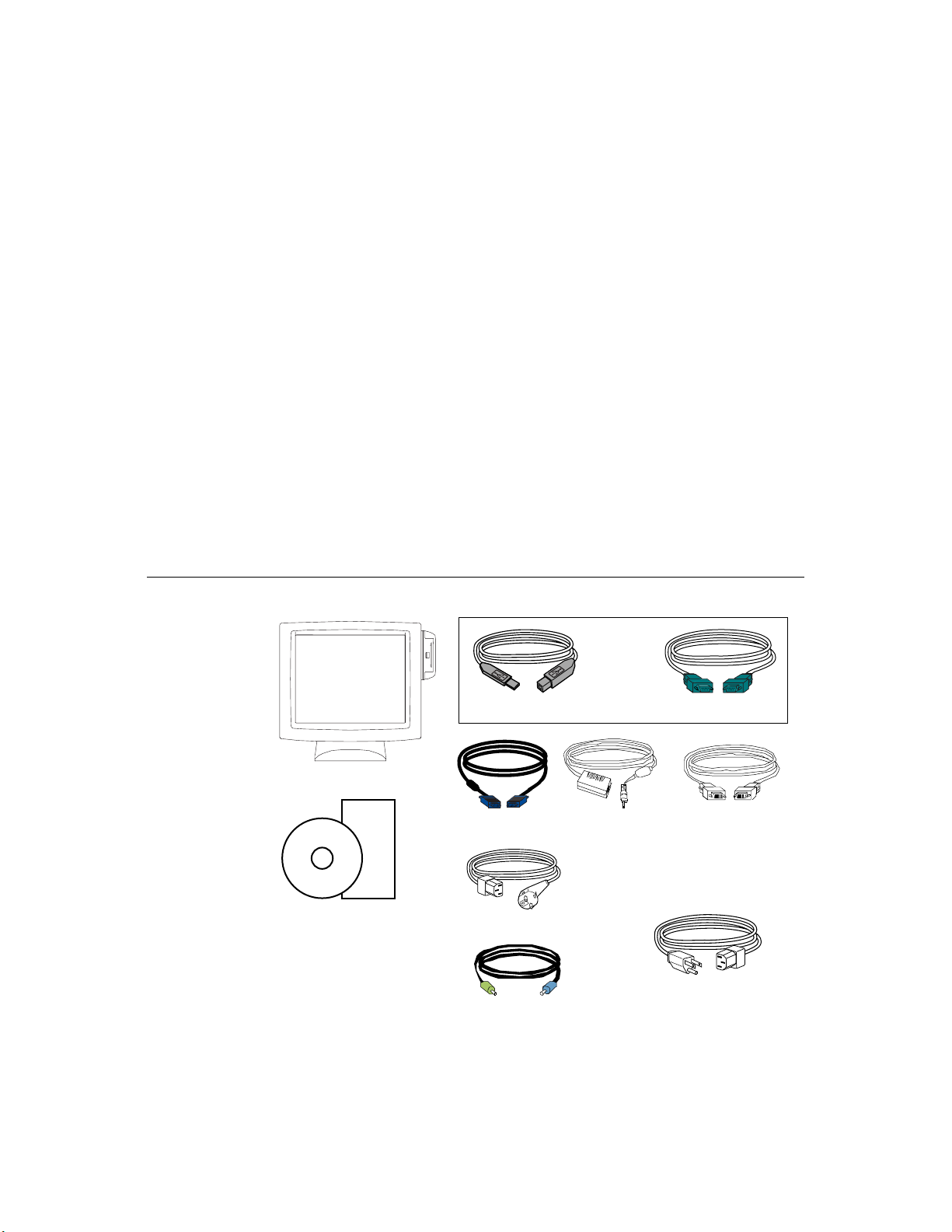
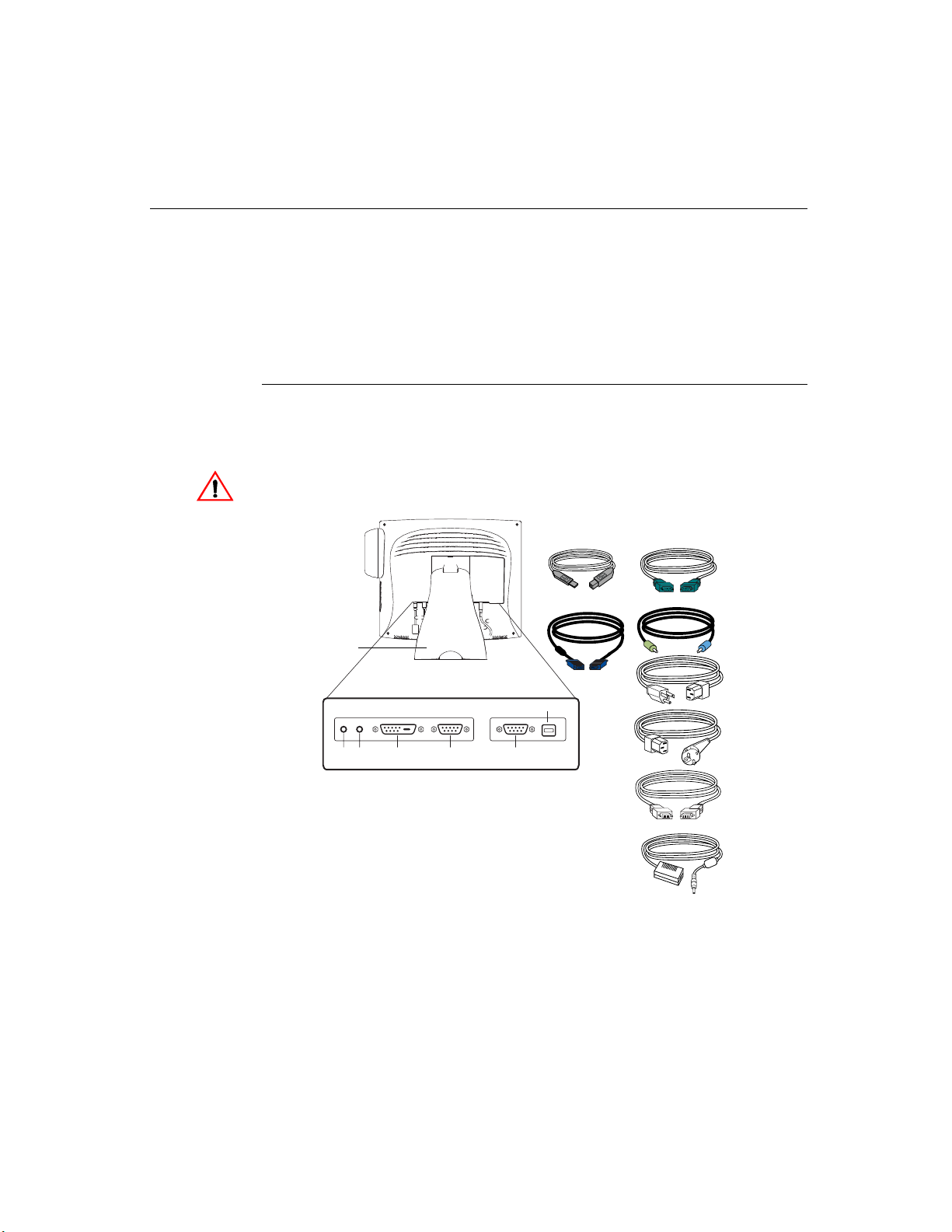
Check that the following 9 items are present and in good condition:
C HAPTER
2
S
ETUP
LCD Display
Quick Install Guide
CD
Software
User Guide-on CD,
Quick Install Guide
and software CD
OR
Video cable
European monitor power cable
Speaker Cable
Adapter
Serial cableUSB touchscreen cable
DVI-D video
cable
Monitor power cable
(US/Canada)
2-3
Page 8
Product Overview
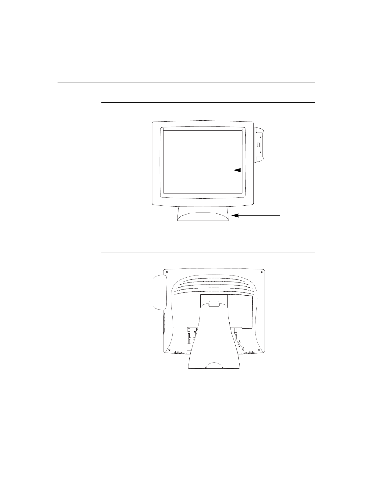
Main Unit
Rear View
LCD Display
Stand
2-4 Elo Entuitive Touchmonitor User Guide
Page 9
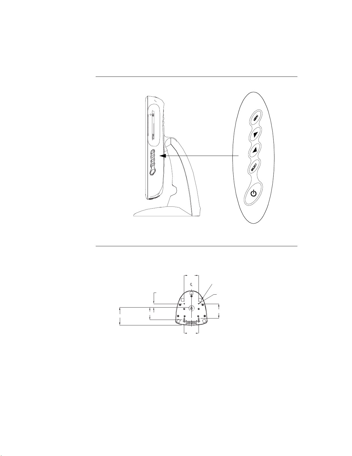
Side View
User Controls
Base Bottom View
123.2
86.6
23.6
100
5X Stability Pad
M5 Mounting Holes (4X)
100
100
Base Bottom
Scale 1:4
2-5
Page 10
Touch Interface Connection
N
OTE
:
Your interface cables may have been pre-connected to your monitor at the factory.
Your touchmonitor comes with one of the following touchscreen connector
cables: Serial (RS-232) cable or USB cable. (For Windows 98, 2000, Me and
XP systems only.)
To set up this display, please refer to the following figures and procedures:
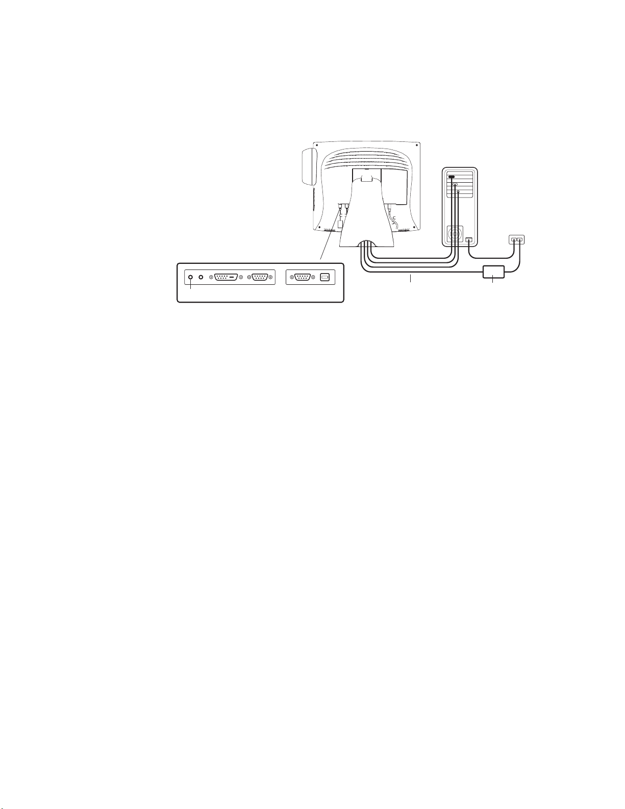
Serial or USB Connection
The following illustrations guide you step by step in connecting your
touchmonitor using a serial cable connection.
CAUTION
Before connecting the cables to your touchmonitor and PC, be sure that the computer
and the touchmonitor are turned off.
Removable back cover
USB cable
OR
Serial touchscreen
cable
Speaker cable
Connections on underside
Power Speaker
port
Female DVI-D
video connector
Female 15-pin
video connector
2-6 Elo Entuitive Touchmonitor User Guide
USB connector
Female 9-pin serial
Touchscreen connector
Video cable
Monitor
power cable
(US/Canada)
European monitor
pow
er cable
DVI-D cable
Adapter
Page 11

Removing the Back Cover
Bottom cut-out
• The cables are routed through the back of the stand.
• To remove the back cover, place one hand at the top of the stand and your
other hand on the bottom cut-out.
• Pull forward from the bottom cut-out and twist the cover until it snaps off.
The cable ports are located on the underside of your touchmonitor.
2-7
Page 12

Routing the Cables
• The cables are routed through the cable management channel in the stand.
2-8 Elo Entuitive Touchmonitor User Guide
Page 13
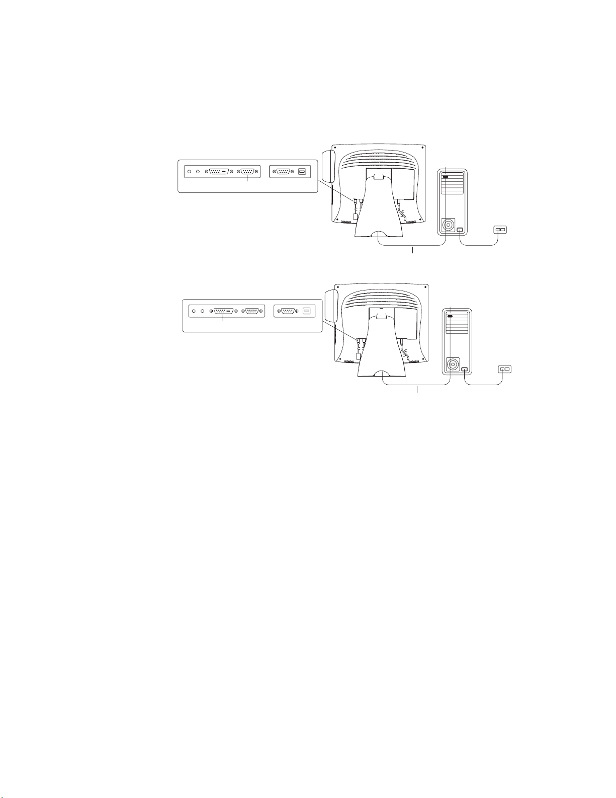
Connecting the Video Cable or DVI-D Video Cable
Connections on underside
Female 15 pin Video connector
Connections on underside
Female DVI-D Video connector
OR
Video cable
Video cable
Video cable
Video port
• Tilt the screen up and out (away from the stand) to access the connection
ports.
• Connect the 15-pin video cable (the ferrite bead end) or the 24-pin DVI-D
cable to the video port on your PC.
• Connect the other end of the video cable to the video connector on your
touchmonitor by routing the cable through the hole in the stand.
• Secure the cable to your touchmonitor and PC by turning the screws on the
connector clockwise.
• Place the cable in the cable management clip.
2-9
Page 14
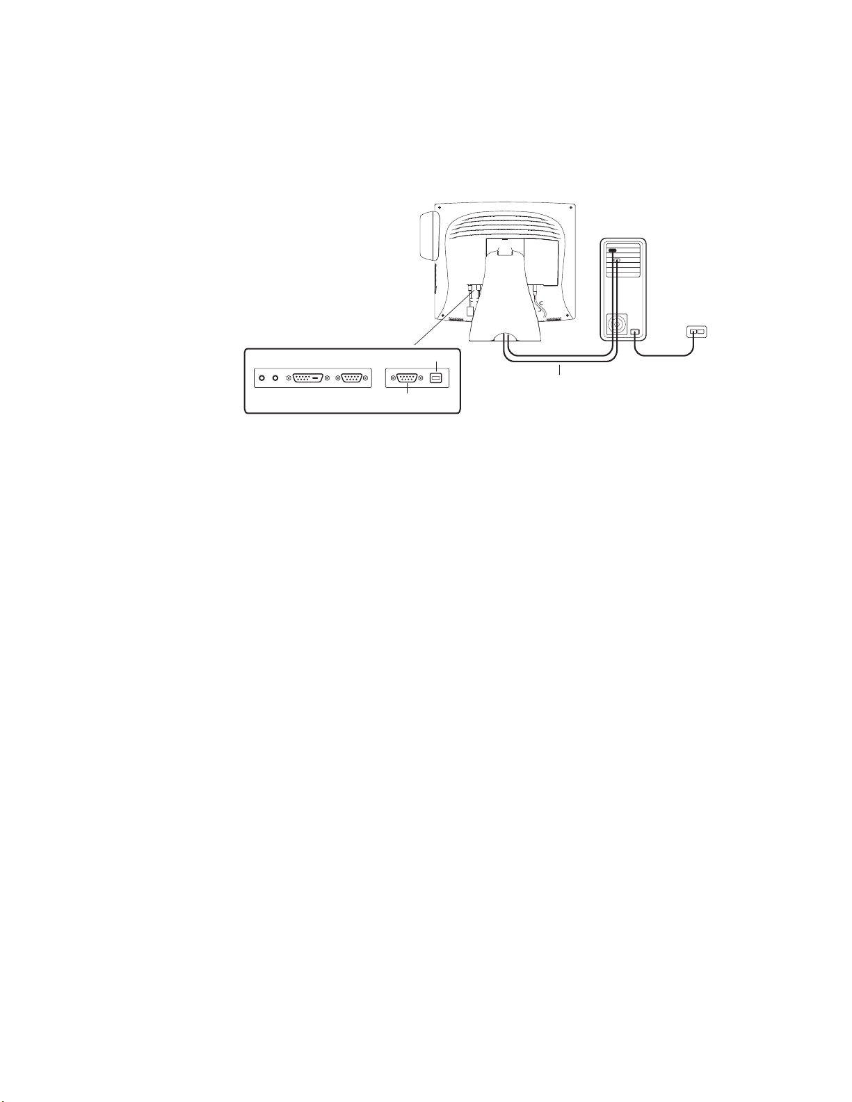
Connecting the Serial or USB Touchscreen Cable
Connections on underside
USB Touchscreen connector
Serial Touchscreen cable
Female 9-pin serial
Touchscreen connector
• Connect the female end of the serial (RS-232) cable to the serial port on the
back of your PC, or connect the USB touchscreen cable to the USB
touchscreen connector on the back of your touchmonitor.
• Connect the male end of the cable to the serial touchscreen connector on your
touchmonitor, or connect the other end of the USB touchscreen cable to your
PC.
• Secure the cable to your touchmonitor and PC by turning the screws on the
connector.
• Route the cable through the cable management clip.
2-10 Elo Entuitive Touchmonitor User Guide
Page 15
N
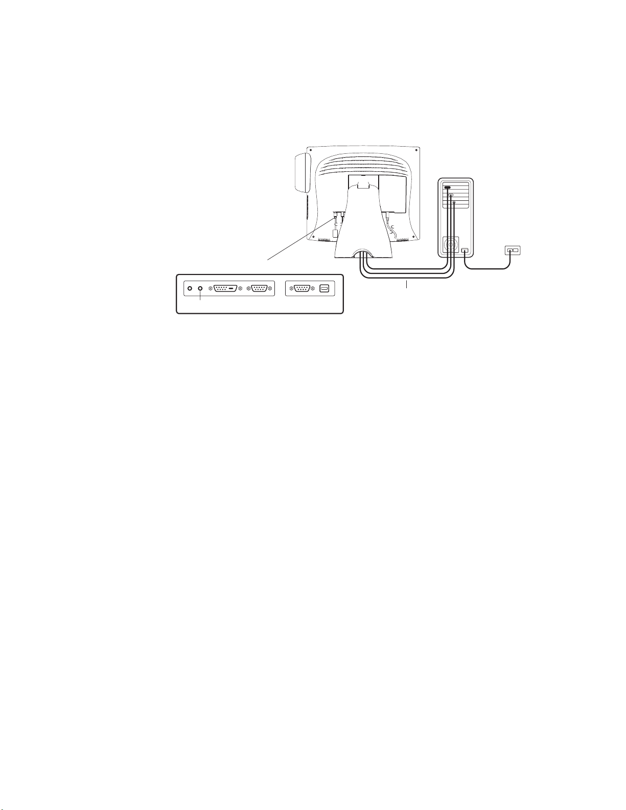
Connecting the Speaker Cable
CONNECTIONS ON UNDERSIDE
SPEAKER CABLE
Speaker port
OTE
:
If you do not wish to connect the speaker cable, go to step 5.
• To use the built in speakers, you need to connect the speaker cable. Connect
the light blue end of the speaker cable to thelight blue speaker port of the
touchmonitor (audio in).
• Connect the lime (light green) end of the speaker cable to the lime speaker
port on your PC (audio out).
2-11
Page 16
Connecting the Power Cable
Connections on Underside
N
Powe r
Power Ca ble
Depending on where you live, you will use either the European or US/Canadian
power cable.
• Connect the female end of the power cable to theBrick power supply.
• Connect the Brick power cable into the power port on the touchmonitor.
• Route the cable through the cable management clip.
OTE
:
To protect your equipment against risk of damage from electrical surges in the power
line, plug the touchmonitor’s power cord into a surge protector, and then connect the
surge protector to a grounded AC electrical outlet.
Replacing the Back Cover
When all the cables have been connected:
• Replace the back stand cover.
• Power on your PC then your touchmonitor. After a brief pause the picture
should appear.
• Tilt the screen up and back to access the connection ports.
• Connect the 15-pin video cable (the ferrite bead end) to the video port on
your PC.
Brick Power Supply
• Connect the other end of the video cable to the video connector on your
touchmonitor by routing the cable through the hole in the stand.
• Secure the cable to your touchmonitor and PC by turning the screws on the
connector clockwise.
• Place the cable in the cable management clip.
• Connect the other end of the USB touchscreen cable to your PC.
2-12 Elo Entuitive Touchmonitor User Guide
Page 17
Optimizing the LCD Display
To ensure the LCD display works well with your computer, configure the
display mode of your graphic card to make it less than or equal to 1024 x 768
resolution, and make sure the timing of the display mode is compatible with the
LCD display. Refer to Appendix A for more information about resolution.
Compatible video modes for your touchmonitor are listed in Appendix C.
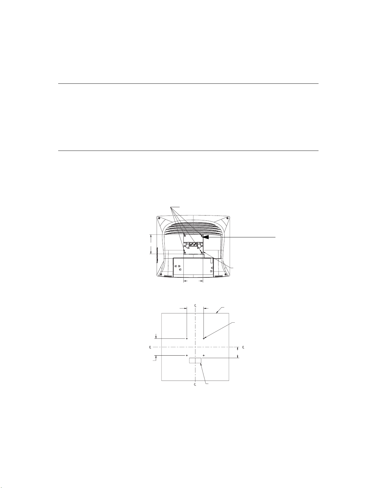
VESA Mount on Your Touchmonitor
Your touchmonitor conforms to the VESA Flat Panel Monitor Physical
Mounting Interface (FPMPMI™) Standard which defines a physical mounting
interface for flat panel monitors, and corresponding standards for flat panel
monitor mounting devices, such as wall and table arms. The VESA mounting
interface is located on the back of your touchmonitor and is shipped
pre-connected to the base.
Remove these four screws
(retain for reassembly)
115
VESA mounting
interface
N
VESA mounting surface is located
12mm below the surface of the
plastic.
115
Wall mount/Surface mount template
100
100
OTE
:
The above drawing displays the VESA mounting interface after the removal of the
Customer wall
(4X) M5
clearance hole
65
70 X 30 cable access hole
mounting cover and base.
2-13
Page 18

N
Accessing the VESA Mounting Interface
If you want to convert your desktop monitor to a wall mount or kiosk monitor,
follow the steps below to access the VESA mounting interface.
OTE
:
You will need a screwdriver for the following steps.
1 Remove the back cover of the stand by pulling forward on the bottom
cut-out.
2 Carefully lay the monitor face down. At the top of the mounting screw cover
there are two slots. With a screwdriver, pry open the mounting screw cover.
The cover fit is tight so remove it carefully.
3 When you remove the mounting screw cover, you will see four screws.
Remove the screws to mount your monitor. Refer to the drawing on page 18.
The following companies provide VESA mounting devices compatible with
your touchmonitor:
Ergotron
800-888-8458
651-681-7600
www.ergotron.com
GCX
800-228-2555
707-773-1100
www.gcx.com
Mounting the Base
You can also mount your touchmonitor by using the keyholes in the base of the
stand. These keyholes provide easy slide on mounting. You can also bolt your
touchmonitor to a tabletop or other flat surface. Please refer to Appendix C for
location and dimension of the mounting holes.
Innovative Office Products
800-524-2744
610-253-9554
www.innov-office-prod.com
MRI
800-688-2414
www.mediarecovery.com
2-14 Elo Entuitive Touchmonitor User Guide
Page 19

Installing the Driver Software
Elo TouchSystems provides driver software that allows your touchmonitor to
work with your computer. Drivers are located on the enclosed CD-ROM for the
following operating systems:
• Windows XP
• Windows 2000
• Windows Me
• Windows 98
• Windows 95
• Windows NT 4.0
Additional drivers and driver information for other operating systems are
available on the Elo TouchSystems web site at www.elotouch.com.
Your Elo touchmonitor is plug-and-play compliant. Information on the video
capabilities of your touchmonitor is sent to your video display adapter when
Windows starts. If Windows detects your touchmonitor, follow the instructions
on the screen to install a generic plug-and-play monitor.
Refer to the appropriate following section for driver installation instructions.
2-15
Page 20

N
Installing the Serial Touch Driver for Windows XP,
Windows 20001, Me, 95/98 and NT 4.0
OTE
:
For Windows 2000 and NT 4.0 you must have administrator access rights to install the
driver.
1 Insert the Elo CD-ROM in your computer’s CD-ROM drive.
If the AutoStart feature for your CD-ROM drive is active, the system
automatically detects the CD and starts the setup program.
2 Follow the directions on the screen to complete the driver setup for your
version of Windows.
If the AutoStart feature is not active:
1 Click Start > Run.
2 Click the Browse button to locate the EloCd.exe program on the CD-ROM.
3 Click Open, then OK to run EloCd.exe.
4 Follow the directions on the screen to complete the driver setup for your
version of Windows.
1.To install Windows 2000 and Windows XP, you must use the "update driver"
method; you will not find a setup.exe file within the download.
2-16 Elo Entuitive Touchmonitor User Guide
Page 21

Installing the Serial Touch Driver for MS-DOS and
Windows 3.1
You must have a DOS mouse driver (MOUSE.COM) installed for your mouse
if you wish to continue using your mouse along with your touchmonitor in
DOS.
To install Windows 3.x and MS-DOS from Windows 95/98, follow the
directions below:
1 Insert the Elo CD-ROM in your computer’s CD-ROM drive.
2 From DOS, type d:\EloDos_W31 to change to the correct directory on the
CD-ROM (your CD-ROM drive may be mapped to a different drive letter).
3 Type install and press Enter to start the installation.
4 Align the touchscreen.
You must have already completed Steps 1 and 2 before proceeding. Refer to
Chapter 2 of the Elo DOS and Windows Driver Guide as necessary for
additional installation information.
To run the INSTALL program:
1 Type INSTALL at the DOS prompt in the directory containing the driver
install files.
2 INSTALL asks you to select the software to install. Then choose
d:\EloDos_W31 from the displayed list.
3 INSTALL also asks you for the paths to use during installation, or you may
use its defaults. INSTALL creates directories as necessary, and warns you if
they exist.
If you are updating your software, you may wish to specify the paths containing
the earlier versions, and overwrite the obsolete files. All executable programs
are upward compatible. For a list of differences from each previous version of
the drivers, be sure to select "Differences from Previous Versions" during the
installation process.
INSTALL updates your AUTOEXEC.BAT file with the drivers you select.
INSTALL makes a copy of your original AUTOEXEC.BAT file, called
AUTOEXEC.OLD. If you already have Elo driver commands in your
AUTOEXEC.BAT file, they will be commented out.
When INSTALL is finished, it leaves a file called GO.BAT in the subdirectory
you specified. GO loads the touchscreen driver, runs the calibration program
ELOCALIB, and gives you some final instructions.
If you are using Windows 3.1, you will also calibrate the touchscreen within
Windows 3.1 with the Touchscreen Control Panel.
2-17
Page 22

Installing the USB Touch Driver
N
Installing the USB Touch Driver for Windows XP,
2
Windows 2000
1 Insert the Elo CD-ROM in your computer’s CD-ROM drive.
If Windows 98, Windows Me or Windows 2000 starts the Add New
Hardware Wizard:
2 Choose Next. Select “Search for the best driver for your device
(Recommended)” and choose Next.
3 When a list of search locations is displayed, place a checkmark on “Specify a
location” and use Browse to select the \EloUSB directory on the Elo
CD-ROM.
4 Choose Next. Once the Elo TouchSystems USB touchscreen driver has been
detected, choose Next again.
5 You will see several files being copied. Insert your Windows 98 CD if
prompted. Choose Finish.
If Windows 98, Windows Me or Windows 2000 does not start the Add New
Hardware Wizard:
OTE
:
For Windows 2000 you must have administrator access rights to install the driver.
1 Insert the Elo CD-ROM in your computer’s CD-ROM drive.
If the AutoStart feature for your CD-ROM drive is active, the system
automatically detects the CD and starts the setup program.
, Me and 98
2 Follow the directions on the screen to complete the driver setup for your
version of Windows.
If the AutoStart feature is not active:
1 Click Start > Run.
2 Click the Browse button to locate the EloCd.exe program on the CD-ROM.
3 Click Open, then OK to run EloCd.exe.
4 Follow the directions on the screen to complete the driver setup for your
version of Windows.
2.To install Windows 2000 and Windows XP, you must use the "update driver"
method; you will not find a setup.exe file within the download.
2-18 Elo Entuitive Touchmonitor User Guide
Page 23

About Touchmonitor Adjustments
Your touchmonitor will unlikely require adjustment. Variations in video output
and application may require adjustments to your touchmonitor to optimize the
quality of the display.
For best performance, your touchmonitor should be operating in native
resolution, that is 1280 x 1024 at 60-75 Hz. Use the Display control panel in
Windows to choose 1280 x 1024 resolution.
C HAPTER
3
C
HAPTER
3
O
PERATION
Operating in other resolutions will degrade video performance. For further
information, please refer to Appendix A.
All adjustments you make to the controls are automatically memorized. This
feature saves you from having to reset your choices every time you unplug or
power your touchmonitor off and on. If there is a power failure your
touchmonitor settings will not default to the factory specifications.
Using the On-Screen Display (OSD) Menus
All adjustments are made by using the on-screen display (OSD) menus. All
menu items can be selected by using the buttons on the side bezel.
N
OTE
:
OSD menu default is enabled.
3-19
Page 24
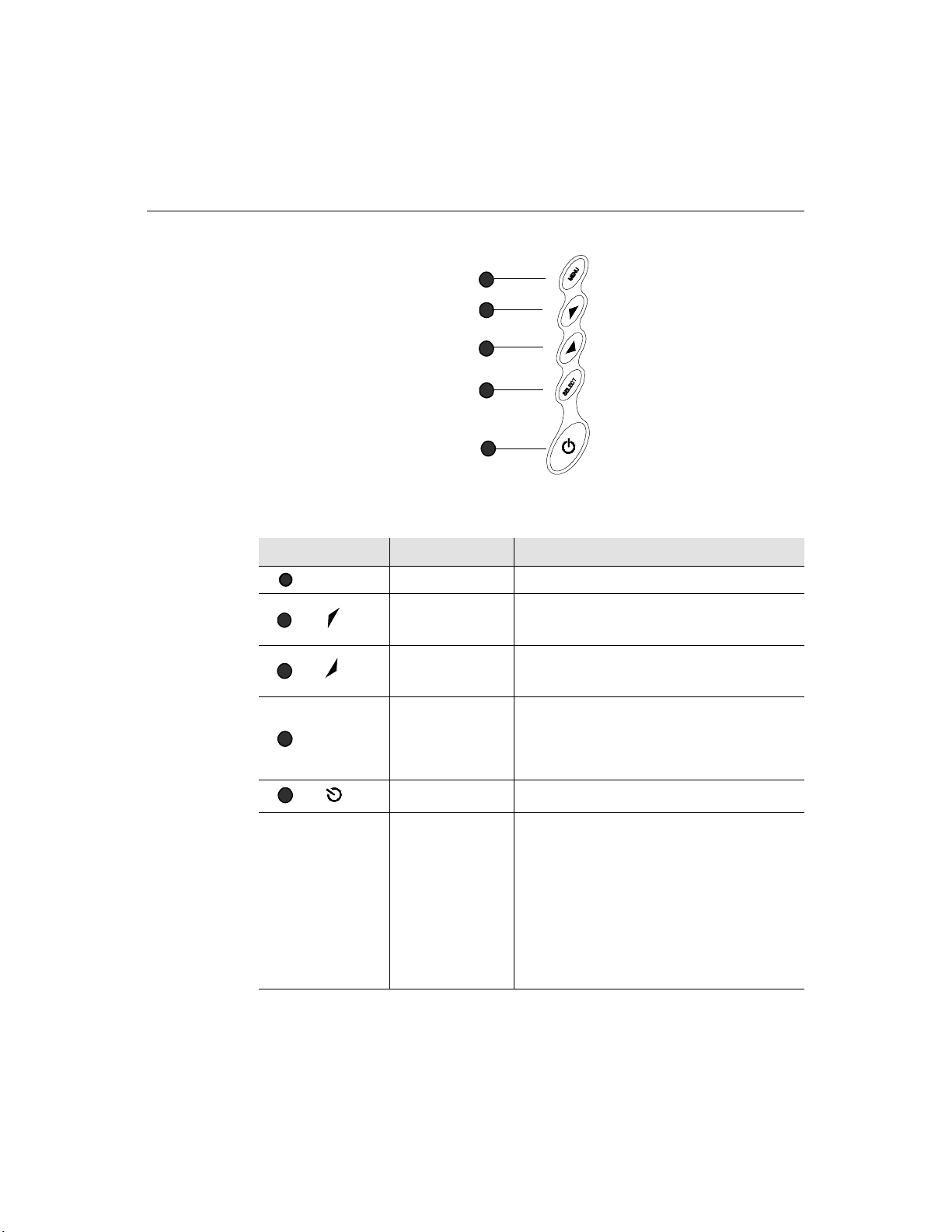
Side Bezel Buttons
MENU
1
2
3
SELECT
4
1
2
3
4
5
Control Function
Menu Display on exit the OSD menus.
Contrast/
Up/Toggle
Volume/Down
Toggle
Enter Select item
1. Shortcut to Contrast adjustment
2. Increase value of adjustment items
3. With menu on toggles OSD options
1. Shortcut to Volume adjustment
2. Decrease value of the adjustment items
3. With menu on toggles OSD options
1. Shortcut to Auto Adjust
2. Select- To select the adjustment items from the
OSD menus.
3. Auto- To activate the “Auto Adjustment”
function to obtain an optimum image.
5
3-20 Elo Entuitive Touchmonitor User Guide
Power Switch Switches the power on/off to your touchmonitor.
Enable/Disable 1. Press the Up and Down buttons at the same
time to enable/disable the MUTE functions. OSD
menu default is enabled
2. Press the Menu and Up buttons at the same
time and hold for two seconds to enable/disable
the OSD functions. OSD menu default is
enabled.
3. Press the Menu and Down buttons at the same
time and hold for two seconds to enable/disable
the power lock function. OSD menu default is
enabled.
Page 25
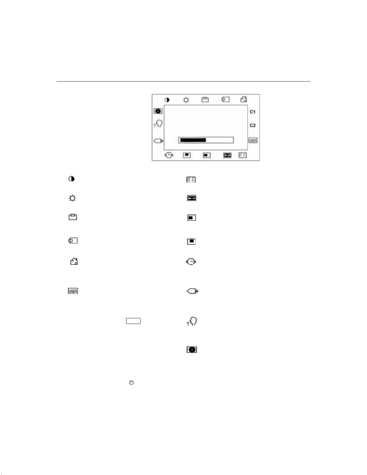
OSD Menu Function
CONTRAST
50
Contrast
Controls the picture contrast
Brightness
Controls the picture brightness
V-Position
Controls the vertical position
H-Position
Controls the horizontal position
Recall Defaults
Recalls factory settings of the image
parameters
C1/C2/USER (Color)
Using these icons, you can select one of
the preset color temperatures (9300°K or
6500°K). Confirm your choice by
pressing the SELECT button. If you
want to change the color temperatures
individually, select USER and confirm by
pressing the OSD button SELECT. Now
you can use the OSD dial to toggle
between the settings R, G and B (red,
green and blue foreground). To change a
setting, first press the SELECT button,
then choose the desired value with the
OSD dial. To confirm the setting, press
the SELECT button again.
If you don’t need to adjust any further
settings, choose the
icon to return to the OSD main menu.
Phase
Controls the vertical fine adjustment
Clock
Controls the horizontal fine adjustment
OSD H-Position
Adjusts the horizontal position of the OSD
menu
OSD V-Position
Adjust the vertical position of the OSD menu
OSD Time
Determines how long (in seconds) the OSD
menu waits before closing automatically after
no action has been performed.
Auto Adjust
Automatically selects the optional settings for
image parameters (brightness, contrast, image
position, phase, etc.)
OSD Language
Selection of the OSD menu language: English,
French, German, Spanish, Japanese.
Image Information
Displays the current graphics mode.
3-21
Page 26

3-22 Elo Entuitive Touchmonitor User Guide
Page 27

If you are experiencing trouble with your touchmonitor, refer to the following
table. If the problem persists, please contact your local dealer or our service
center.
Solutions to Common Problems
Problem Suggestion(s)
C HAPTER
4
C
HAPTER
4
T
ROUBLESHOOTING
No image appears on screen. Check that all the I/O and power connectors are properly
“Out of Range” display Check to see if the resolution of your computer is higher
connected as described in Chapter 2.
Make sure the pins of the connectors are not crooked or
broken.
Test power supply by trying different cables, a different
wall outlet or plug another appliance into the outlet.
Make certain the video cable is properly connected and that
it is not damaged. Check for bent pins on the cable
connectors.
Ensure that your computer and video card are properly
configured. (Consult video card documentation.)
than that of the LCD display.
Reconfigure the resolution of your computer to make it less
than or equal to
information on resolution.
1280 x 1024. See Appendix A for more
4-23
Page 28

Image has vertical flickering line bars. Use “PHASE” to make an adjustment.
Check and reconfigure the display mode of the vertical
refresh rate of your graphic card to make it compatible with
the LCD display.
Image is unstable and flickering Use “CLOCK” to make an adjustment.
Image is scrolling Make sure the VGA signal cable (or adapter) is well
connected.
Check and reconfigure the display mode of the vertical
refresh rate of your graphic card to make it compatible with
the LCD display.
Touch doesn’t work Make sure cable is securely attached at both ends.
4-24 Elo Entuitive Touchmonitor User Guide
Page 29

A PPENDIX
A
C
HAPTER
4
N
ATIVE
The native resolution of a monitor is the resolution level at which the LCD
panel is designed to perform best. For the Elo LCD touchmonitor, the native
resolution is 1280 x 1024 for the SXGA-17 inch size. In almost all cases, screen
images look best when viewed at their native resolution. You can lower the
resolution setting of a monitor but not increase it.
Input Video 17" LCD
640x480 (VGA) Transforms input format to 1280x1024
800x600 (SVGA) Transforms input format to 1280x1024
1024x768 (XGA) Transforms input format to 1280x1024
1280x1024 (SXGA) Displays in Native Resolution
R
ESOLUTION
The native resolution of an LCD is the actual number of pixels horizontally in
the LCD by the number of pixels vertically in the LCD. LCD resolution is
usually represented by the following symbols:
VGA
SVGA
XGA
SXGA
UXGA
640x480
800x600
1024x768
1280x1024
1600x1200
A-25
Page 30

As an example, a SVGA resolution LCD panel has 800 pixels horizontally by
600 pixels vertically. Input video is also represented by the same terms. XGA
input video has a format of 1024 pixels horizontally by 768 pixels vertically.
When the input pixels contained in the video input format match the native
resolution of the panel, there is a one to one correspondence of mapping of input
video pixels to LCD pixels. As an example, the pixel in column 45 and row 26
of the input video is in column 45 and row 26 of the LCD. For the case when
the input video is at a lower resolution than the native resolution of the LCD, the
direct correspondence between the video pixels and the LCD pixels is lost. The
LCD controller can compute the correspondence between video pixels and LCD
pixels using algorithms contained on its controller. The accuracy of the
algorithms determines the fidelity of conversion of video pixels to LCD pixels.
Poor fidelity conversion can result in artifacts in the LCD displayed image such
as varying width characters.
A-26 Elo Entuitive Touchmonitor User Guide
Page 31

A PPENDIX
B
C
HAPTER
4
T
OUCHMONITOR
This manual contains information that is important for the proper setup and
maintenance of your touchmonitor. Before setting up and powering on your new
touchmonitor, read through this manual, especially Chapter 2 (Installation), and
Chapter 3 (Operation).
1 To reduce the risk of electric shock, follow all safety notices and never open
the touchmonitor case.
2 Turn off the product before cleaning
S
AFETY
3 Your new touchmonitor is equipped with a 3-wire, grounding power cord.
The power cord plug will only fit into a grounded outlet. Do not attempt to fit
the plug into an outlet that has not been configured for this purpose. Do not
use a damaged power cord. Use only the power cord that comes with your
Elo TouchSystems Touchmonitor. Use of an unauthorized power cord may
invalidate your warranty.
4 The slots located on the sides and top of the touchmonitor case are for
ventilation. Do not block or insert anything inside the ventilation slots.
5 It is important that your touchmonitor remains dry. Do not pour liquid into or
onto your touchmonitor. If your touchmonitor becomes wet do not attempt to
repair it yourself.
B-27
Page 32

Care and Handling of Your Touchmonitor
The following tips will help keep your Elo Entuitive touchmonitor functioning
at the optimal level.
• To avoid risk of electric shock, do not disassemble the brick supply or
display unit cabinet. The unit is not user serviceable. Remember to unplug
the display unit from the power outlet before cleaning.
• Do not use alcohol (methyl, ethyl or isopropyl) or any strong dissolvent. Do
not use thinner or benzene, abrasive cleaners or compressed air.
• To clean the display unit cabinet, use a cloth lightly dampened with a mild
detergent.
• Avoid getting liquids inside your touchmonitor. If liquid does get inside,
have a qualified service technician check it before you power it on again.
• Do not wipe the screen with a cloth or sponge that could scratch the surface.
• To clean the touchscreen, use window or glass cleaner. Put the cleaner on the
rag and wipe the touchscreen. Never apply the cleaner directly on the
touchscreen
B-28 Elo Entuitive Touchmonitor User Guide
Page 33

A PPENDIX
C
C
HAPTER
0
T
ECHNICAL
Compatible Video Modes
Your Elo Entuitive touchmonitor is compatible with the following standard
video modes:
Mode Resolution H. Frequency (kHz) V. Frequency (Hz)
IBM & VESA VGA 720 x 400 31.47 70.09
IBM & VESA VGA 640 x 480 31.47 59.94
IBM & VESA VGA 640 x 480 37.86 72.81
IBM & VESA VGA 640 x 480 37.50 75.00
VESA SVGA 800 x 600 35.16 56.25
VESA SVGA 800 x 600 37.88 60.32
VESA SVGA 800 x 600 48.08 72.19
VESA SVGA 800 x 600 46.88 75.00
VESA XGA 1024 x 768 48.36 60.00
VESA XGA 1024 x 768 56.48 70.07
VESA XGA 1024 x 768 60.02 75.03
VESA SXGA 1280 x 1024 64 60
VESA SXGA 1280 x 1024 80 75
VESA SXGA 1152 x 864 67.5 75
Apple Macintosh 16” 832 x 624 49.73 74.55
NEC FC-98 series 640 x 400 24.83 56.42
NEC FC-98 series 640 x 400 31.47 70.01
NEC FC-98 series 640 x 480 31.47 59.94
S
PECIFICATIONS
C-29
Page 34

Touchmonitor Specifications
17" LCD Touchmonitor (ET17-XXWF-1) Specifications
Display Type
Size
Pixel Format
Touchscreen
Colors
Display Brightness
Back-light Lamp Life
Viewing Angle
(typical) (CR=10)
Viewing Angle
(typical) (CR=5)
Contrast Ratio
Display Response
Time
Environmental
Humidity
Mechanical
Active matrix, thin film transistor
(TFT), liquid crystal display
17-inch diagonal Horizontal: 13.3” (338mm) useful screen
area
Vertical: 10.6” (270mm) useful screen
area
1280 x 1024
0.125-inch IntelliTouch and
AccuTouch, anti-glare
IntelliTouch or AccuTouch
16.7 million with dithering, 6 bits
per color data
250 cd/m² typical AccuTouch: 205 cd/m² typical
IntelliTouch: 230 cd/m² typical
typical 40,000 hours to half
brightness
Horizontal
Vertical
Horizontal
Vertical
450:1 typical
16 msec (typical)
Operating Temp
Storage Temp
Operating Temp
Storage Temp
Weight 21.6 lbs. (9.82 kg.) maximum approx.
Size See drawings in this Appendix.
±70° or 140° total
±70° or 140° total
±80° or 160° total
±80° or 160° total
0°C to 40°C
-20°C to +60°C
20%-80%
5%-95% noncondensing
weight for IntelliTouch and AccuTouch
Electrical
Speakers
Agencies
C-30 Elo Entuitive Touchmonitor User Guide
Input Video
Input Power
Power Dissipation
8 ohms, 1 watt per speaker
Safety & EMC UL, cUL, FCC-B, IC, CE, TÜV-GS,
Analog (no proprietary video card
needed); Digital Video Input (DVI-D)
100-240 VAC, 50/60 Hz.
45 W max.
VCCI, and C-Tick
Page 35

IntelliTouch Touchmonitor Specifications
Mechanical
Positional Accuracy
Touchpoint Density
Touch Activation Force
Surface Durability
Expected Life Performance
Sealing
Optical
Light Transmission (per ASTM
D1003)
Visual Resolution
Gloss (per ASTM D2457 using a
60-degree gloss meter)
Environmental
Chemical Resistance
Electrostatic Protection
(per EN 61 000-4-2, 1995)
Standard deviation of error is less than 0.080 in. (2.03 mm). Equates to
less than ±1%.
More than 100,000 touchpoints/in2 (15,500 touchpoints/cm2).
Typically less than 3 ounces (85 grams).
Surface durability is that of glass, Mohs’ hardness rating of 7.
No known wear-out mechanism, as there are no layers, coatings, or
moving parts. IntelliTouch technology has been operationally tested to
more than 50 million touches in one location without failure, using a
stylus similar to a finger.
Unit is sealed to protect against splashed liquids, dirt, and dust.
90%
All measurements made using USAF 1951 Resolution Chart, under 30X
magnification, with test unit located approximately 1.5 in (38 mm) from
surface of resolution chart.
Clear surface: Excellent, with no noticeable degradation.
Antiglare surface: 6:1 minimum.
Antiglare surface: Curved: 60 ± 20 gloss units or 75 ± 15 gloss units.
The active area of the touchscreen is resistant to all chemicals that do
not affect glass, such as:
Acetone
Toluene
Methyl ethyl ketone
Isopropyl alcohol
Methyl alcohol
Ethyl acetate
Ammonia-based glass cleaners
Gasoline
Kerosene
Vinegar
Meets Level 4 (15 kV air/8 kV contact discharges).
C-31
Page 36

AccuTouch Touchmonitor Specifications
Mechanical
Construction
Positional Accuracy
Touchpoint Density
Touch Activation Force
Surface Durability
Expected Life
Performance
Optical
Light Transmission
(per ASTM D1003)
Visual Resolution
Haze (per ASTM D1003)
Gloss (per ASTM D2457)
Top: Polyester with outside hard-surface coating with clear or antiglare
finish.
Inside: Transparent conductive coating.
Bottom: Glass substrate with uniform resistive coating. Top and bottom
layers separated by Elo-patented separator dots.
Standard deviation of error is less than 0.080 in. (2.03 mm). This equates to
less than ±1%.
More than 100,000 touchpoints/in² (15,500 touchpoints/cm²).
Typically less than 4 ounces (113 grams).
Meets Taber Abrasion Test (ASTM D1044), CS-10F wheel, 500 g. Meets
pencil hardness 3H.
AccuTouch technology has been operationally tested to greater than 35
million touches in one location without failure, using a stylus similar to a
finger.
Typically 75% at 550-nm wavelength (visible light spectrum).
All measurements made using USAF 1951 Resolution Chart, under 30 X
magnification, with test unit located approximately 1.5 in. (38 mm) from
surface of resolution chart.
Antiglare surface: 6:1 minimum.
Antiglare surface: Less than 15%.
Antiglare surface: 90 ± 20 gloss units tested on a hard-coated front surface.
C-32 Elo Entuitive Touchmonitor User Guide
Page 37

17" LCD Touchmonitor Dimensions
478
434
338
429
370
43
270.3
219
C-33
Page 38

67.7
See Detail A
123.2
See Detail A
86.6
23.6
100
100
Base Bottom
Scale 1:4
239
5X Stability Pad
M5 Mounting Holes (4X)
100
279
10.8
Detail A
Detail A
Scale 1:1
6.5
R3.25
R6.25
C-34 Elo Entuitive Touchmonitor User Guide
Page 39

C
HAPTER
0
R
EGULATORY INFORMATION
I. Electrical Safety Information:
A) Compliance is required with respect to the voltage, frequency, and current
requirements indicated on the manufacturer’s label. Connection to a different
power source than those specified herein will likely result in improper operation,
damage to the equipment or pose a fire hazard if the limitations are not followed.
B) There are no operator serviceable parts inside this equipment. There are hazardous voltages generated by this equipment which constitute a safety hazard. Service
should be provided only by a qualified service technician.
C) This equipment is provided with a detachable power cord which has an integral
safety ground wire intended for connection to a grounded safety outlet.
1) Do not substitute the cord with other than the provided approved type.
Under no circumstances use an adapter plug to connect to a 2-wire outlet as
this will defeat the continuity of the grounding wire.
2) The equipment requires the use of the ground wire as a part of the safety
certification, modification or misuse can provide a shock hazard that can
result in serious injury or death.
3) Contact a qualified electrician or the manufacturer if there are questions
about the installation prior to connecting the equipment to mains power.
II. Emissions and Immunity Information
A) Notice to Users in the United States: This equipment has been tested and found
to comply with the limits for a Class B digital device, pursuant to Part 15 of FCC
Rules. These limits are designed to provide reasonable protection against harmful
interference in a residential installation. This equipment generates, uses, and can
radiate radio frequency energy, and if not installed and used in accordance with the
instructions, may cause harmful interference to radio communications.
B) Notice to Users in Canada: This equipment complies with the Class B limits for
radio noise emissions from digital apparatus as established by the Radio Interference Regulations of Industrie Canada.
C) Notice to Users in the European Union: Use only the provided power cords and
interconnecting cabling provided with the equipment. Substitution of provided
cords and cabling may compromise electrical safety or CE Mark Certification for
emissions or immunity as required by the following standards:
35
Page 40

This Information Technology Equipment (ITE) is required to have a CE Mark
on the manufacturer’s label which means that the equipment has been tested
to the following Directives and Standards:
This equipment has been tested to the requirements for the CE Mark as
required by EMC Directive 89/336/EEC indicated in European Standard EN
55 022 Class B and the Low Voltage Directive 73/23/EEC as indicated in
European Standard EN 60 950.
D) General Information to all Users: This equipment generates, uses and can radiate radio frequency energy. If not installed and used according to this manual the
equipment may cause interference with radio and television communications.
There is, however, no guarantee that interference will not occur in any particular
installation due to site-specific factors.
1) In order to meet emission and immunity requirements, the user must
observe the following:
a) Use only the provided I/O cables to connect this digital device with
any computer.
b) To ensure compliance, use only the provided manufacturer’s approved
line cord.
c) The user is cautioned that changes or modifications to the equipment
not expressly approved by the party responsible for compliance could
void the user’s authority to operate the equipment.
2) If this equipment appears to cause interference with radio or television
reception, or any other device:
a) Verify as an emission source by turning the equipment off and on.
b) If you determine that this equipment is causing the interference, try to
correct the interference by using one or more of the following measures:
i) Move the digital device away from the affected receiver.
ii) Reposition (turn) the digital device with respect to the affected
receiver.
iii) Reorient the affected receiver’s antenna.
iv) Plug the digital device into a different AC outlet so the digital
device and the receiver are on different branch circuits.
v) Disconnect and remove any I/O cables that the digital device
does not use. (Unterminated I/O cables are a potential source of
high RF emission levels.)
vi) Plug the digital device into only a grounded outlet receptacle.
Do not use AC adapter plugs. (Removing or cutting the line cord
ground may increase RF emission levels and may also present a
lethal shock hazard to the user.)
If you need additional help, consult your dealer, manufacturer, or an experienced radio or television technician.
36 Elo Entuitive Touchmonitor User Guide
Page 41

N10051
37
Page 42

38 Elo Entuitive Touchmonitor User Guide
Page 43

C
HAPTER
0
W
ARRANTY
Except as otherwise stated herein or in an order acknowledgment delivered to
Buyer, Seller warrants to Buyer that the Product shall be free of defects in
materials and workmanship. The warranty for the touchmonitors and
components of the product is 1 year.
Seller makes no warranty regarding the model life of components. Seller’s
suppliers may at any time and from time to time make changes in the
components delivered as Products or components.
Buyer shall notify Seller in writing promptly (and in no case later than thirty
(30) days after discovery) of the failure of any Product to conform to the
warranty set forth above; shall describe in commercially reasonable detail in
such notice the symptoms associated with such failure; and shall provide to
Seller the opportunity to inspect such Products as installed, if possible. The
notice must be received by Seller during the Warranty Period for such product,
unless otherwise directed in writing by the Seller. Within thirty (30) days after
submitting such notice, Buyer shall package the allegedly defective Product in
its original shipping carton(s) or a functional equivalent and shall ship to Seller
at Buyer’s expense and risk.
Within a reasonable time after receipt of the allegedly defective Product and
verification by Seller that the Product fails to meet the warranty set forth above,
Seller shall correct such failure by, at Seller’s options, either (i) modifying or
repairing the Product or (ii) replacing the Product. Such modification, repair, or
replacement and the return shipment of the Product with minimum insurance to
Buyer shall be at Seller’s expense. Buyer shall bear the risk of loss or damage in
transit, and may insure the Product. Buyer shall reimburse Seller for
transportation cost incurred for Product returned but not found by Seller to be
defective. Modification or repair, of Products may, at Seller’s option, take place
either at Seller’s facilities or at Buyer’s premises. If Seller is unable to modify,
repair, or replace a Product to conform to the warranty set forth above, then
Seller shall, at Seller’s option, either refund to Buyer or credit to Buyer’s
account the purchase price of the Product less depreciation calculated on a
straight-line basis over Seller’s stated Warranty Period.
39
Page 44

THESE REMEDIES SHALL BE THE BUYER’S EXCLUSIVE REMEDIES
FOR BREACH OF WARRANTY. EXCEPT FOR THE EXPRESS
WARRANTY SET FORTH ABOVE, SELLER GRANTS NO OTHER
WARRANTIES, EXPRESS OR IMPLIED BY STATUTE OR OTHERWISE,
REGARDING THE PRODUCTS, THEIR FITNESS FOR ANY PURPOSE,
THEIR QUALITY, THEIR MERCHANTABILITY, THEIR
NONINFRINGEMENT, OR OTHERWISE. NO EMPLOYEE OF SELLER
OR ANY OTHER PARTY IS AUTHORIZED TO MAKE ANY WARRANTY
FOR THE GOODS OTHER THAN THE WARRANTY SET FORTH
HEREIN. SELLER’S LIABILITY UNDER THE WARRANTY SHALL BE
LIMITED TO A REFUND OF THE PURCHASE PRICE OF THE PRODUCT.
IN NO EVENT SHALL SELLER BE LIABLE FOR THE COST OF
PROCUREMENT OR INSTALLATION OF SUBSTITUTE GOODS BY
BUYER OR FOR ANY SPECIAL, CONSEQUENTIAL, INDIRECT, OR
INCIDENTAL DAMAGES.
Buyer assumes the risk and agrees to indemnify Seller against and hold Seller
harmless from all liability relating to (i) assessing the suitability for Buyer’s
intended use of the Products and of any system design or drawing and (ii)
determining the compliance of Buyer’s use of the Products with applicable
laws, regulations, codes, and standards. Buyer retains and accepts full
responsibility for all warranty and other claims relating to or arising from
Buyer’s products, which include or incorporate Products or components
manufactured or supplied by Seller. Buyer is solely responsible for any and all
representations and warranties regarding the Products made or authorized by
Buyer. Buyer will indemnify Seller and hold Seller harmless from any liability,
claims, loss, cost, or expenses (including reasonable attorney’s fees) attributable
to Buyer’s products or representations or warranties concerning same.
40 Elo Entuitive Touchmonitor User Guide
Page 45

Index
Numerics
17" LCD Touchmonitor (ET17-XXWF-1) Specifications, 30
17" LCD Touchmonitor Dimensions, 33
A
About the Product, 1
About Touchmonitor Adjustments, 19
Accessing the VESA Mounting Interface, 14
AccuTouch Touchmonitor Specifications, 32
Agencies, 30
Auto Adjust, 21
B
Back-light Lamp Life, 30
Base Bottom View, 5
Brightness, 21
C
C1/C2/USER (Color), 21
Care and Handling of Your Touchmonitor, 28
Chemical Resistance, IntelliTouch, 31
Cleaning Your Touchmonitor, 28
Clock, 21
Colors, 30
Compatible Video Modes, 29
Connecting the Power Cable, 12
Connecting the Serial or USB Touchscreen Cable, 10
Connecting the Speaker Cable, 11
Connecting the Video Cable or DVI-D Video Cable, 9
Construction, AccuTouch, 32
Contrast, 20, 21
Contrast Ratio, 30
D
Display Brightness, 30
Display Response Time, 30
Display Type, 30
E
Electrical, 30
Electrical Safety Information, 35
Electrostatic Protection, IntelliTouch, 31
Emissions and Immunity Information, 35
Enable/Disable, 20
Environmental, 30, 31
Ergotron, 14
Expected Life Performance, AccuTouch, 32
Expected Life Performance, IntelliTouch, 31
G
GCX, 14
Gloss, AccuTouch, 32
Gloss, IntelliTouch, 31
H
Haze, AccuTouch, 32
H-Position, 21
Humidity, 30
I
Image Information, 21
Image problem, 23
Image, scrolling, 24
Image, unstable, 24
Image, vertical flickering, 24
Innovative Office Products, 14
Installation and Setup, 3
Installing the Driver Software, 15
Installing the Serial Touch Driver for MS-DOS and
Windows 3.1, 17
Installing the Serial Touch Driver for Windows XP,
Windows 2000, Me, 95/98 and NT 4.0, 16
Installing the USB Touch Driver, 18
Installing the USB Touch Driver for Windows XP, Windows
2000, Me and 98, 18
IntelliTouch Touchmonitor Specifications, 31
Introduction, 1
L
Light Transmission, AccuTouch, 32
Light Transmission, IntelliTouch, 31
M
Main Unit, 4
Mechanical, 30
Mechanical, AccuTouch, 32
Mechanical, IntelliTouch, 31
Menu, 20
Minus Counter-clockwise, 20
Mounting the Base, 14
MRI, 14
Index-41
Page 46

N
Native Resolution, 25
O
Operation, 19
Optical, AccuTouch, 32
Optical, IntelliTouch, 31
Optimizing the LCD Display, 13
OSD H-Position, 21
OSD Language, 21
OSD Menu Function, 21
OSD Time, 21
OSD V-Position, 21
Out of Range display, 23
P
Phase, 21
Pixel Format, 30
Plus/Clockwise, 20
Positional Accuracy, AccuTouch, 32
Positional Accuracy, IntelliTouch, 31
Power Switch, 20
Precautions, 1
Product Overview, 4
R
Rear View, 4
Recall Defaults, 21
Regulatory Information, 35
Removing the Back Cover, 7
Replacing the Back Cover, 12
Routing the Cables, 8
Surface Durability, AccuTouch, 32
Surface Durability, IntelliTouch, 31
SVGA, 25
SXGA, 25
T
Technical Specifications, 29
Touch Activation Force, AccuTouch, 32
Touch Activation Force, IntelliTouch, 31
Touch Interface Connection, 6
Touch not working, 24
Touchmonitor Safety, 27
Touchmonitor Specifications, 30
Touchpoint Density, AccuTouch, 32
Touchpoint Density, IntelliTouch, 31
Touchscreen, 30
Troubleshooting, 23
U
Unpacking Your Touchmonitor, 3
Using the On-Screen Display (OSD) Menus, 19
UXGA, 25
V
VESA Mount on Your Touchmonitor, 13
VGA, 25
Viewing Angle (typical) (CR=10), 30
Viewing Angle (typical) (CR=5), 30
Visual Resolution, AccuTouch, 32
Visual Resolution, IntelliTouch, 31
Volume, 20
V-Position, 21
S
Sealing, IntelliTouch, 31
Serial or USB Connection, 6
Side Bezel Buttons, 20
Side View, 5
Solutions to Common Problems, 23
Speakers, 30
W
Warranty, 39
X
XGA, 25
Index-42
Page 47

PORT POWERED
SWIPE READER
TECHNICAL REFERENCE MANUAL
Manual Part Number 99875094 Rev 10
JULY 2001
20725 South Annalee Avenue
Carson, CA 90746
Phone: (310) 631-8602
FAX: (310) 631-3956
Technical Support: (888) 624-8350
www.magtek.com
Page 48

Copyright 1997-2001
MAG-TEK, Inc.
Printed in the United States of America
Information in this document is subject to change without notice. No part of this document may
be reproduced or transmitted in any form or by any means, electronic or mechanical, for any
purpose, without the express written permission of Mag-Tek, Inc.
Mag-Tek is a registered trademark of Mag-Tek, Inc.
Procomm is a registered trademark of Datastorm Technologies, Inc.
REVISIONS
Rev Number Date Notes
1 11 Dec 97 Initial Release
2 18 Dec 97 Sec 1 Changed spec Dimensions; Sec 1, 3 Changed illustrations
for clarity.
3 11 May 98 Sections 1, 2, and 3 revised to reflect latest firmware revisions.
Sec 4 deleted.
4 15 Jun 98 Two part numbers added.
5 1 Mar 99 Sec 1, Added 3 part numbers, changed specs, Changed
Dimensions Figure 1-3, removed Figure 1-4, Mounting
Dimensions, added Mag-Tek Windows Drivers; Added note to
Table 1-1.
Section 2, added mounting instructions and Figure 2-1, Mounting
Dimensions. Section 3, added 3 track symbols to Table 3-1 and
3 sign-on configurations to 3-2.
6 14 Jun 99 Title change, Removed MT-211 and RS-232; Sec 1, Table 1-1,
added Pin List for Cable 21040077, added RS-232
Communication; Sec 2, added Demo Program from Net; Sec 3,
Clarified Fig 3-1, Described firmware P/Ns and revisions.
7 1 Dec 99 Section 1: Added P/N 21040084, Updated table for 9- and 25-pin
connectors; Section 3: Added P/N 21040084 to Sign-on table.
8 21 Sep 00 Editorial changes throughout. Sec 1: Configuration list expanded
and moved to Sec 3; Specification weight changed from 5.9 oz to
5.8oz, Converted symbols to Metric System [SI]. Sec 3: Added 5
new part numbers with firmware, tracks, and configurations.
9 09 Mar 01 Front Matter: Corrected Agency Approvals to include
Class B for FCC and Class B for CE. Changed RMA Warranty
address to 20801 S. Annalee. Section 3: Removed “Track 3 – 7
bit” line from Table 3-1. Added 094 and 096 configurations in
Table 3-2.
10 25 Jul 01 Front Matter: Agency Approvals: Corrected Class B for CE and
Corrected UL and CUL . Copyright 2001 added.
ii
Page 49

Limited Warranty
Mag-Tek, Inc. (hereinafter “Mag-Tek”) warrants this Mag-Tek product IN ITS ENTIRETY, to
be in good working order for a period of one year from the date of purchase from Mag-Tek.
Should this product fail to be in good working order at any time during this warranty period,
Mag-Tek will, at its option, repair or replace this product at no additional charge except as set
forth below. Repair parts and replacement products will be furnished on an exchange basis and
will be either reconditioned or new. All replaced parts and products become the property of
Mag-Tek. This limited warranty does not include service to repair damage to the product
resulting from accident, disaster, misuse, abuse, or non-Mag-Tek modification of the product.
Limited Warranty service may be obtained by delivering the product during the warranty period
to Mag-Tek (20801 S. Annalee Ave., Carson, CA 90746). If this product is delivered by mail,
you agree to insure the product or assume the risk of loss or damage in transit, to prepay shipping
charges to the warranty service location and to use the original shipping container or equivalent.
ALL EXPRESS AND IMPLIED WARRANTIES FOR THIS PRODUCT, INCLUDING THE
WARRANTIES OF MERCHANTABILITY AND FITNESS FOR A PARTICULAR
PURPOSE, ARE LIMITED IN DURATION TO A PERIOD OF ONE YEAR FROM THE
DATE OF PURCHASE, AND NO WARRANTIES, WHETHER EXPRESS OR IMPLIED,
WILL APPLY AFTER THIS PERIOD, EXCEPT AS PROVIDED IN THE PRECEDING
SENTENCE. EACH PURCHASER UNDERSTANDS THAT THE MAG-TEK PRODUCT IS
OFFERED AS IS.
IF THIS PRODUCT IS NOT IN GOOD WORKING ORDER AS WARRANTED ABOVE,
YOUR SOLE REMEDY SHALL BE REPAIR OR REPLACEMENT AS PROVIDED ABOVE.
IN NO EVENT WILL MAG-TEK BE LIABLE TO YOU FOR ANY DAMAGES,
INCLUDING ANY LOST PROFITS, LOST SAVINGS OR OTHER INCIDENTAL OR
CONSEQUENTIAL DAMAGES ARISING OUT OF THE USE OF OR INABILITY TO USE
SUCH PRODUCT, EVEN IF MAG-TEK HAS BEEN ADVISED OF THE POSSIBILITY OF
SUCH DAMAGES, OR FOR ANY CLAIM BY ANY OTHER PARTY.
THIS WARRANTY GIVES YOU SPECIFIC LEGAL RIGHTS, AND YOU MAY ALSO
HAVE OTHER RIGHTS WHICH VARY FROM STATE TO STATE.
iii
Page 50

FCC WARNING STATEMENT
This equipment has been tested and found to comply with the limits for Class B digital device, pursuant to
Part 15 of FCC Rules. These limits are designed to provide reasonable protection against harmful
interference when the equipment is operated in a residential environment. This equipment generates,
uses, and can radiate radio frequency energy and, if not installed and used in accordance with the
instruction manual, may cause harmful interference to radio communications. However, there is no
guarantee that interference will not occur in a particular installation.
FCC COMPLIANCE STATEMENT
This device complies with Part 15 of the FCC Rules. Operation of this device is subject to the following
two conditions: (1) This device may not cause harmful interference; and (2) this device must accept any
interference received, including interference that may cause undesired operation.
CANADIAN DOC STATEMENT
This digital apparatus does not exceed the Class B limits for radio noise for digital apparatus set out in the
Radio Interference Regulations of the Canadian Department of Communications.
Le présent appareil numérique n’émet pas de bruits radioélectriques dépassant les limites applicables
aux appareils numériques de las classe B prescrites dans le Réglement sur le brouillage radioélectrique
édicté par les ministère des Communications du Canada.
CE STANDARDS
Testing for compliance to CE and FCC requirements was performed by an independent laboratory. The
unit under test was found compliant to Class B.
UL/CSA
This product is recognized per Underwriter Laboratories and Canadian Underwriter Laboratories 1950.
iv
Page 51

TABLE OF CONTENTS
SECTION 1. FEATURES AND SPECIFICATIONS --------------------------------------------------------------------- 1
MAG-TEK DEVICE DRIVERS FOR WINDOWS ---------------------------------------------------------------------- 1
FEATURES--------------------------------------------------------------------------------------------------------------------- 1
CONFIGURATION------------------------------------------------------------------------------------------------------------ 2
SPECIFICATIONS ------------------------------------------------------------------------------------------------------------ 3
SECTION 2. INSTALLATION ------------------------------------------------------------------------------------------------ 5
REQUIREMENTS------------------------------------------------------------------------------------------------------------- 5
MOUNTING--------------------------------------------------------------------------------------------------------------------- 5
INSTALLATION AND TEST ------------------------------------------------------------------------------------------------ 6
SECTION 3. OPERATION ----------------------------------------------------------------------------------------------------- 9
LED INDICATOR-------------------------------------------------------------------------------------------------------------- 9
CARD READ ------------------------------------------------------------------------------------------------------------------- 9
READER TO HOST MESSAGE FORMAT ----------------------------------------------------------------------------- 9
TIMING FOR ID SIGN ON -------------------------------------------------------------------------------------------------10
FIGURES
Figure 1-1. Port-Powered Swipe Reader-----------------------------------------------------------------------------------vi
Figure 1-2. Reader Cable and Optional Adapter ------------------------------------------------------------------------- 2
Figure 1-3. Dimensions---------------------------------------------------------------------------------------------------------4
Figure 2-1. Mounting Hole Dimensions For Surface -------------------------------------------------------------------- 6
Figure 3-1. Timing For ID Sign-on and Transmission Bursts. --------------------------------------------------------10
TABLES
Table 1-1. OEM and 9-Pin Connectors and 25-Pin Adapter ---------------------------------------------------------- 2
Table 1-2. Specifications------------------------------------------------------------------------------------------------------- 3
Table 3-1. SS and ES Track Symbols -------------------------------------------------------------------------------------- 9
Table 3-2. Sign-on ID for Configurations----------------------------------------------------------------------------------11
v
Page 52

vi
Figure 1-1. Port-Powered Swipe Reader
Page 53

SECTION 1. FEATURES AND SPECIFICATIONS
The Port Powered Swipe Reader is a compact magnetic stripe card reader which conforms to
ISO/ANSI standards. The Reader is compatible with the PC series of personal computers or any
device with a serial RS-232 interface. A card is read by sliding it, stripe down and facing the
LED side, through the slot either forward or backward.
A green LED (Light Emitting Diode) indicator on the Reader panel provides the operator with
continuous status of the Reader operations.
When power is applied, the Reader transmits a sign-on ID message. About 150 milliseconds
after DTR is applied, the Reader sends the part number of the firmware in the following form:
21088819A01 <CR>. The first 8 characters indicate the firmware number; the letter is the
revision, which is followed by a revision sublevel of 01 to 99. The <CR> indicates carriage
return (0x0D). The sign-on messages for part numbers are listed in Section 3. Timing is also
shown in Section 3.
Since the input voltage is supplied by a relatively low source of power, the Reader depends on its
input capacitor to maintain proper charge during all operations. In order to reduce the drain on
this internal power source during data transmission, the output data is transmitted in 5 to 6
millisecond bursts with a 10-millisecond gap between bursts to allow the capacitor to recharge.
The PC software should be able to tolerate this 10-millisecond space between characters. The
Timing is shown is Section 3, Figure 3-1. Configurations, including part numbers, firmware,
tracks, and unit configuration, are listed in Section 3, Table 3-2.
MAG-TEK DEVICE DRIVERS FOR WINDOWS
The Mag-Tek Device Drivers for Windows, Part Number 30037385, may be used with the Port
Powered Swipe Reader. When this program is used, refer to Mag-Tek Device Driver for
Windows, Programming Reference Manual, Part Number 99875125.
FEATURES
Major features of the Swipe Reader are as follows:
• Powered through the RS-232 serial port – no external power supply required
• Hardware Compatible with PC or any computer or terminal with an RS-232 interface
• Software Compatible with Procomm, or any RS-232 communications program
• Bidirectional card reading
• Reads encoded data that meets ANSI/ISO/CDL/AAMVA standards
• Green LED for status
1
Page 54

Port Powered Swipe Reader
CONFIGURATION
The Reader, LED Indicator, pin numbers for the 9-pin connector, and the Adapter are shown in
Figure 1-2.
Figure 1-2. Reader Cable and Optional Adapter
Pin numbers and signal descriptions for the 9-pin (DE9) cable and 25-pin (DB25) adapter shown
in the illustration are listed in Table 1-1. Also listed is the pin list OEM version, P/N 21040077.
Table 1-1. OEM and 9-Pin Connectors and 25-Pin Adapter
Connector for OEM
Version 21040077
J2 on the PCB
- 1 NC*
1 3 2 RXD (to PC)
2 2 3 TXD** (from PC)
3 20 4 DTR (from PC)
4 7 5 GND
- 6-9 NC*
* No Connection
** Pin must be connected to TXD (or DTR if TXD not available).
25-pin
Adapter
DE9-pin
Connector
Signal
2
Page 55

Section 1. Features and Specifications
SPECIFICATIONS
Table 1-2 lists the specifications for the Port Powered Swipe Reader. Figure 1-3 shows the
dimensions for the standard product. Other sizes are available by special order.
Table 1-2. Specifications
OPERATING
Reference Standards ISO/ANSI/ CDL/ AAMVA*
Power Input From RS-232 interface
Recording Method Two-frequency coherent phase (F2F)
Message Format ASCII
Card Speed 3 to 50 IPS
MTBF Electronics: 125,000 hours. Head: 1,000,000 passes
ELECTRICAL
DTR Voltage 5 to 15 VDC
Current
Quiescent
Transmitting
Peak at Power On
RS-232 Communication 9600 bps, no parity, 8 data bits, 1 stop bit
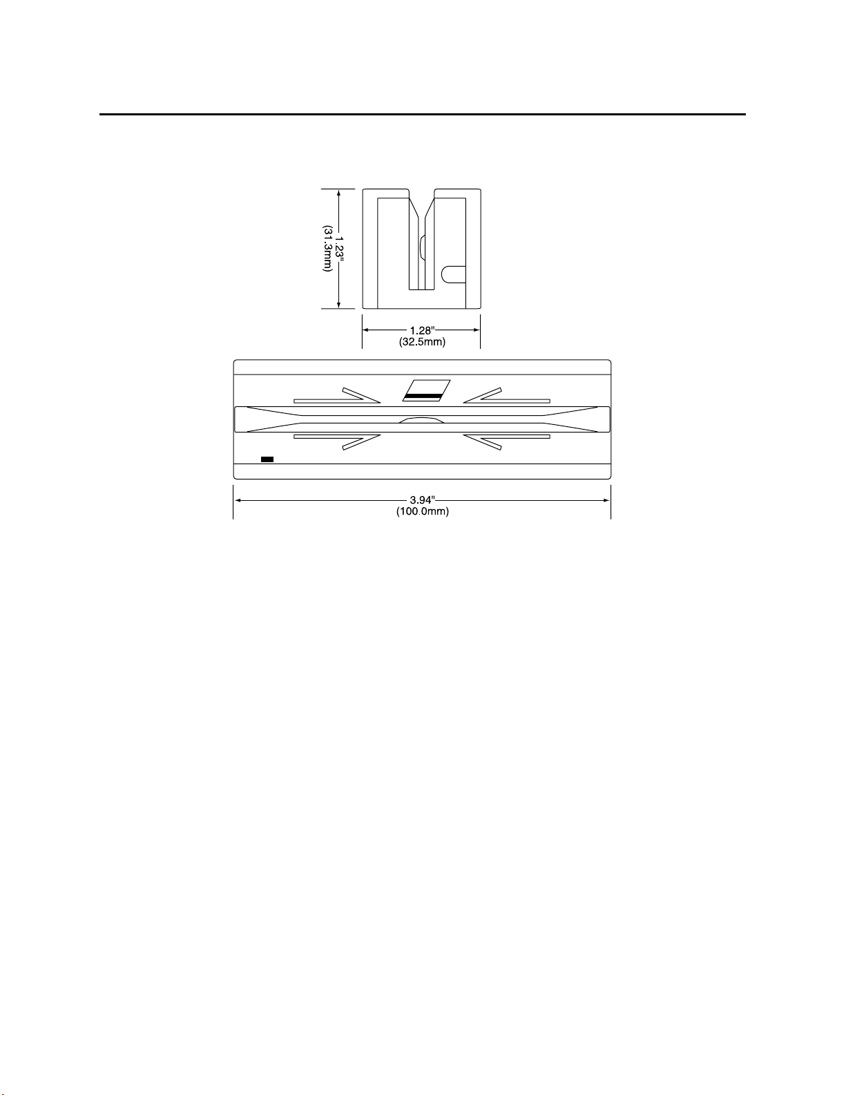
Dimensions Length: 3.94” (100.0 mm),
Weight Reader 5.8 oz. (165 gr.)
Cable length 5 Ft. (1.5 m)
Connector 9 pin D female (May require a 25-pin adapter)
Temperature
Operating 32oF to 131oF (0oC to 55oC)
Storage -22oF to 158oF (-30oC to 70oC)
Humidity
Operating 10% to 90% noncondensing
Storage Up to 100% noncondensing
Altitude
Operating 0-10,000 ft. (0-3048 m.)
Storage 0-50,000 ft. (0-15240 m.)
1 to 2 mA typical (continuous)
8 to 9 mA typical (5 ms duration)
12 mA
MECHANICAL (STANDARD PRODUCT)
Width: 1.28” (32.5 mm)
Height: 1.23” (31.3 mm)
ENVIRONMENTAL
* ISO (International Standards Organization), ANSI (American National Standards Institute), CDL
(California Drivers License), and AAMVA (American Association of Motor Vehicle Administrators).
3
Page 56
Port Powered Swipe Reader
Figure 1-3. Dimensions
4
Page 57

SECTION 2. INSTALLATION
The hardware installation consists of plugging the cable into the PC and optional adapter, if
required, Com Port setup, and testing the Reader.
REQUIREMENTS
• Port Powered Swipe Reader
• Optional 9- to 25-pin Adapter, P/N 78200018
• PC with Com Port
• Procomm, Hyper Terminal, Mag-Tek Windows Drivers, or other RS-232 communications
program
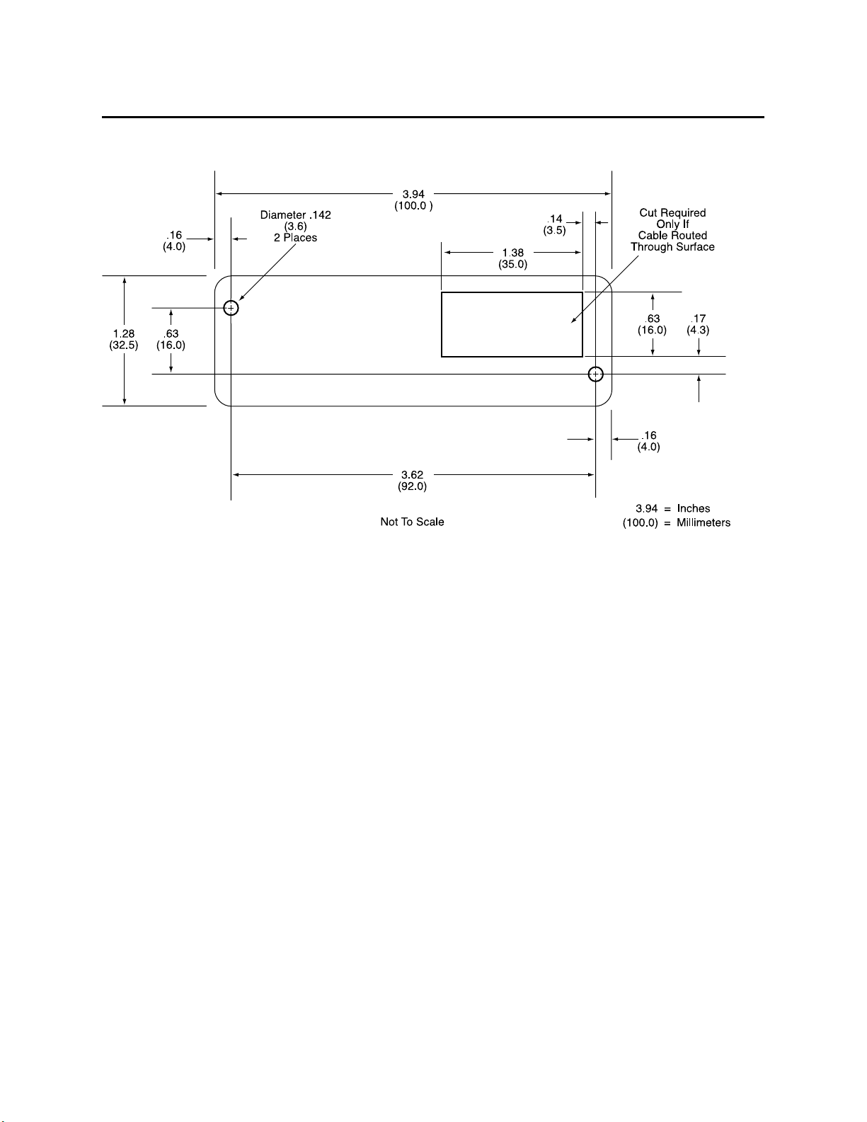
MOUNTING
1. The Reader can be mounted on a surface in three ways:
• By two screws through the surface attached to the bottom of the unit and running the
cable on the top of the surface;
• By two screws through the surface attached to the bottom of the unit and by drilling a
hole in the surface for the cable and running the cable through the hole;
• By attaching the unit to the surface with fastening tape and running the cable on the top
of the surface.
Note
The two mounting inserts are 3 mm diameter; 0.5 mm pitch; 6.4
mm deep. The length of the screws used depends on the mounting
surface thickness and the thickness of washers (if used).
The mounting dimensions are shown in Figure 2-1. Determine the method of mounting
required.
2. Ensure the Reader is positioned on a flat, accessible surface with at least 4 inches
clearance on either end for room to swipe a card. Orient the Reader so the side with the
LED is facing the direction of intended use.
If fastening tape is to be used, clean the area that the Reader will be mounted on with
isopropyl alcohol. Remove the adhesive protective cover on the fastening tape, and
position the Reader and push down firmly.
5
Page 58
Port Powered Swipe Reader
Figure 2-1. Mounting Hole Dimensions For Surface
3. Mount the Reader.
INSTALLATION AND TEST
To install the Swipe Reader, perform the following steps:
1. Connect the Swipe Reader cable connector into a 9-pin serial Com Port on the PC. If a
25-pin Adapter is required, plug the 9-pin connector on the Reader into the Adapter, and
the adapter into the PC.
2. Open a communications program such as the Mag-Tek Encoder/Reader Demonstration
Program, which may be obtained from the Internet at www.magtek.com. Navigate to the
Demo Programs and select Reader & Encoder Demos (Win 95/98/NT).
3. On the program, select the Com Port the Reader is connected to.
4. If the Com Port selected is correct, the green LED on the Reader will light; if the wrong
Com Port is selected, the LED will not light.
5. Select the baud rate of 9600.
Page 59

Section 2. Installation
6. Select 8 data bits, no parity, 1 stop bit.
7. With the LED on, swipe a card. The data on the screen will show Track 1 beginning with
“%” and ending with “?”. Track 2 begins with “;” and ends with “?”. Track 3 begins
with “+” (normal) or "!" (CDL) and ends with “?”. The following is an example:
%B123^Smith/Joann^9812101000?;112222333333444444444?<0x0D>
If a track cannot be read, an E will appear in place of the track data; for example, if
Track 2 is bad and Tracks 1 and 3 are good, the display will be similar to the following:
%11111111111111111111?;E?+3333333333333333333?<0x0D>
If Tracks 1 and 3 are bad and Track 2 is good, the display will be similar to the following:
%E?;22222222222222222222?+E?<0x0D>
8. If the data on the screen is not numeric or alphanumeric similar to the above, check the
communications rate. If the alphanumeric characters are similar to the above, the unit is
ready for operation.
7
Page 60

Port Powered Swipe Reader
8
Page 61

SECTION 3. OPERATION
Included in this section are Indicator, Card Read, Reader to Host Message Format, and a timing
diagram of sign-on ID.
LED INDICATOR
A green LED indicator on the panel gives the operator the status of the Reader. If the cabling is
correct and the correct Com Port is selected, the indicator will be on. If the indictor does not
come on, check the cabling and the Com Port. The LED is turned off during a card swipe and
while the unit is transmitting.
CARD READ
A card may be swiped through the Reader slot when the green LED is lit. The magnetic stripe
must face toward the front (the side with the LED) and may be swiped in either direction.
READER TO HOST MESSAGE FORMAT
Track data is sent in the following order: SS, Card Data, ES.
The format in which data is transmitted (in track order) after a card is read successfully is as
follows:
SS CARD DATA ES CR
Carriage Return
End Sentinel
Card Data or "E" (for Error)
Start Sentinel Character
Table 3-1 lists Start Sentinel and End Sentinel symbols.
Table 3-1. SS and ES Track Symbols
Start Sentinel End Sentinel Description
% ? Track 1
; ? Track 2
+ ? Track 3 - ISO
# ? Track 3 - AAMVA
! ? Track 3 - CDL
9
Page 62
Port Powered Swipe Reader
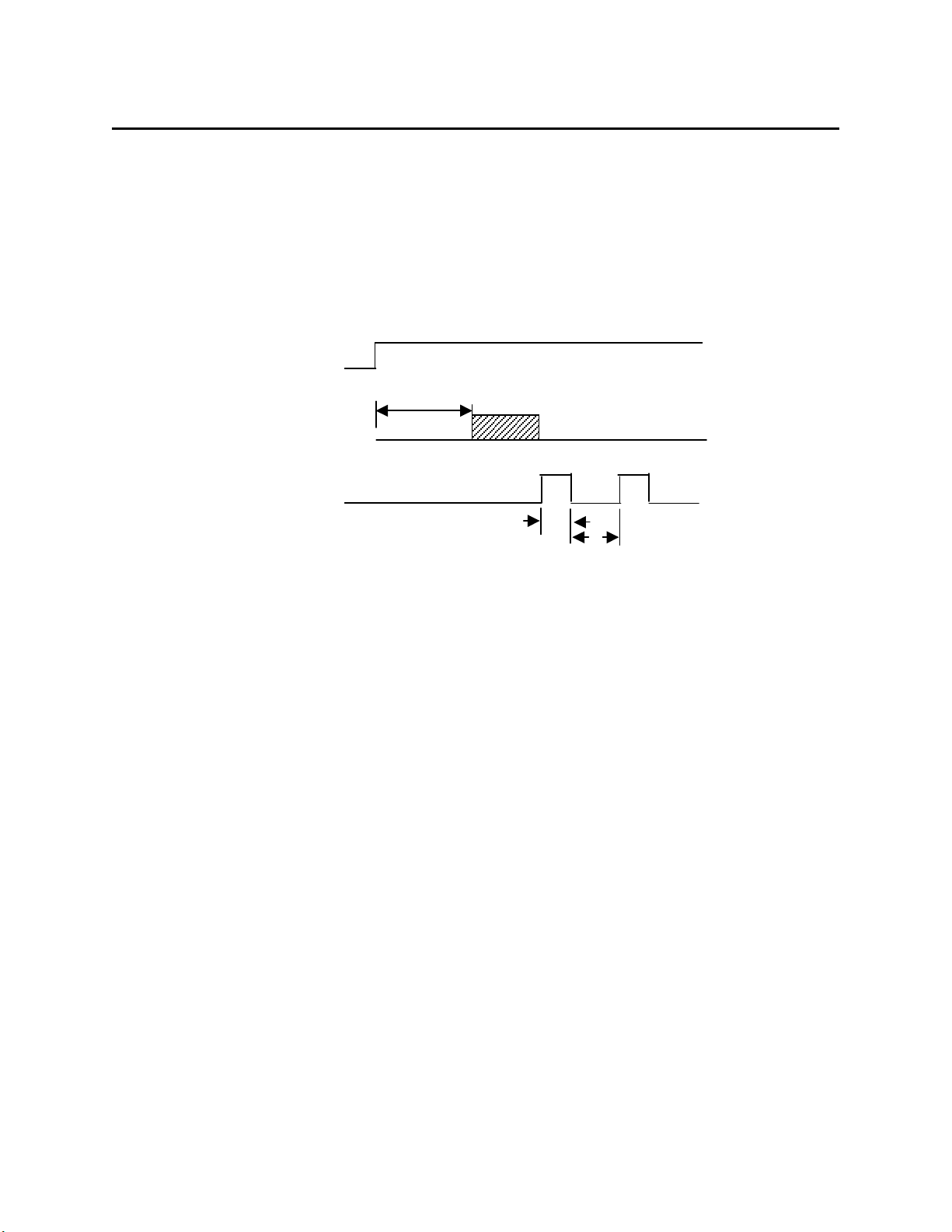
TIMING FOR ID SIGN ON
Timing for the ID Sign-on and transmission bursts (5 ms with 10 ms between bursts) are shown
in Figure 3-1.
DTR
150 ms
Sign-on ID
Transmission
Burst
5 ms
10 ms
Figure 3-1. Timing For ID Sign-on and Transmission Bursts.
The firmware controls the operation of Sign-on ID and Transmission bursts in the following
format:
210888xxLnn <CR>
Where:
the first 8 digits are the firmware part number (xx represents the Swipe Reader series),
L is the alpha revision,
nn is the number sub-revision.
<CR> is 0x0D.
10
Page 63

Section 3. Operation
Table 3-2 lists the available part number, firmware, and configuration.
Table 3-2. Sign-on ID for Configurations
Part Number Firmware Track Configuration Configuration*
21040071 21088811 1,2 Pearl White
21040073 21088812 2,3 Pearl White
21040074 21088817 1,2,3 Pearl White
21040075 21088814 2 Pearl White
21040077 21088817 1,2,3 Black, No Cover, No Cable
21040079 21088811 1,2 Black
21040080 21088814 2 Black
21040081 21088811 1,2 Black (150 mm)
21040082 21088817 1,2,3 Black
21040084 21088811 1,2 Pearl White
(with STX and ETX)
21040086 21088817 1,2,3 Pearl White, No Cover, 12" Cable, 6-pin
21040088 21088824 1,2,3 Pearl White, 4800/7O, 10' cable
21040089 21088811 1,2 Pearl White, 10' cable
21040091 21088811 1,2 Black, No Cover, 5.9" Cable, 4-pin
21040092 21088817 1,2,3 Pearl White, 5 m cable
21040094 21068811 1,2 Pearl White, No Cover
21040096 21088811 1,2 Black, 4” Cable, 4-pin
*All cables are 6' DE9 unless otherwise specified.
11
Page 64

USB (UNIVERSAL SERIAL BUS)
SWIPE READER
TECHNICAL REFERENCE MANUAL
Manual Part Number 99875191 Rev 4
AUGUST 2001
20725 South Annalee Avenue
Carson, CA 90746
Phone: (310) 631-8602
FAX: (310) 631-3956
Technical Support: (888) 624-8350
www.magtek.com
Page 65

Copyright 2001
MAG-TEK, Inc.
Printed in the United States of America
Information in this document is subject to change without notice. No part of this document may
be reproduced or transmitted in any form or by any means, electronic or mechanical, for any
purpose, without the express written permission of Mag-Tek, Inc.
Mag-Tek is a registered trademark of Mag-Tek, Inc.
USB (Universal Serial Bus) Specification is Copyright¤ 1998 by Compaq Computer
Corporation, Intel Corporation, Microsoft Corporation, NEC Corporation.
REVISIONS
Rev Number Date Notes
1 15 Jun 01 Initial Release
2 22 Jun 01 Section 4. On Tracks 1, 2, and 3 Decode
Status delete “more than eight bits of data”
and add “data on it that is not noise.” From
Card Encode Type, Value 3, delete “This
device does not detect blank cards so this
value will never occur.”
3 25 Jul 01 Front Matter: Agency Approvals: Corrected
Class B for CE.
4 17 Aug 01 Section 4, Report Descriptor: Changed
Logical Maximum from 25 ff to 26 ff 00.
ii
Page 66

Limited Warranty
Mag-Tek, Inc. (hereinafter “Mag-Tek”) warrants this Mag-Tek product IN ITS ENTIRETY, to
be in good working order for a period of one year from the date of purchase from Mag-Tek.
Should this product fail to be in good working order at any time during this warranty period,
Mag-Tek will, at its option, repair or replace this product at no additional charge except as set
forth below. Repair parts and replacement products will be furnished on an exchange basis and
will be either reconditioned or new. All replaced parts and products become the property of
Mag-Tek. This limited warranty does not include service to repair damage to the product
resulting from accident, disaster, misuse, abuse, or non-Mag-Tek modification of the product.
Limited Warranty service may be obtained by delivering the product during the warranty period
to Mag-Tek (20801 S. Annalee Ave., Carson, CA 90746). If this product is delivered by mail,
you agree to insure the product or assume the risk of loss or damage in transit, to prepay shipping
charges to the warranty service location and to use the original shipping container or equivalent.
ALL EXPRESS AND IMPLIED WARRANTIES FOR THIS PRODUCT, INCLUDING THE
WARRANTIES OF MERCHANTABILITY AND FITNESS FOR A PARTICULAR
PURPOSE, ARE LIMITED IN DURATION TO A PERIOD OF ONE YEAR FROM THE
DATE OF PURCHASE, AND NO WARRANTIES, WHETHER EXPRESS OR IMPLIED,
WILL APPLY AFTER THIS PERIOD, EXCEPT AS PROVIDED IN THE PRECEDING
SENTENCE. EACH PURCHASER UNDERSTANDS THAT THE MAG-TEK PRODUCT IS
OFFERED AS IS.
IF THIS PRODUCT IS NOT IN GOOD WORKING ORDER AS WARRANTED ABOVE,
YOUR SOLE REMEDY SHALL BE REPAIR OR REPLACEMENT AS PROVIDED ABOVE.
IN NO EVENT WILL MAG-TEK BE LIABLE TO YOU FOR ANY DAMAGES,
INCLUDING ANY LOST PROFITS, LOST SAVINGS OR OTHER INCIDENTAL OR
CONSEQUENTIAL DAMAGES ARISING OUT OF THE USE OF OR INABILITY TO USE
SUCH PRODUCT, EVEN IF MAG-TEK HAS BEEN ADVISED OF THE POSSIBILITY OF
SUCH DAMAGES, OR FOR ANY CLAIM BY ANY OTHER PARTY.
THIS WARRANTY GIVES YOU SPECIFIC LEGAL RIGHTS, AND YOU MAY ALSO
HAVE OTHER RIGHTS WHICH VARY FROM STATE TO STATE.
iii
Page 67

FCC WARNING STATEMENT
This equipment has been tested and found to comply with the limits for Class B digital device, pursuant to
Part 15 of FCC Rules. These limits are designed to provide reasonable protection against harmful
interference when the equipment is operated in a residential environment. This equipment generates,
uses, and can radiate radio frequency energy and, if not installed and used in accordance with the
instruction manual, may cause harmful interference to radio communications. However, there is no
guarantee that interference will not occur in a particular installation.
FCC COMPLIANCE STATEMENT
This device complies with Part 15 of the FCC Rules. Operation of this device is subject to the following
two conditions: (1) This device may not cause harmful interference; and (2) this device must accept any
interference received, including interference that may cause undesired operation.
CANADIAN DOC STATEMENT
This digital apparatus does not exceed the Class B limits for radio noise for digital apparatus set out in the
Radio Interference Regulations of the Canadian Department of Communications.
Le présent appareil numérique n’émet pas de bruits radioélectriques dépassant les limites applicables aux
appareils numériques de las classe B prescrites dans le Réglement sur le brouillage radioélectrique édicté
par les ministère des Communications du Canada.
CE STANDARDS
Testing for compliance to CE requirements was performed by an independent laboratory. The unit under
test was found compliant to Class B.
UL/CSA
This product is recognized per Underwriter Laboratories and Canadian Underwriter Laboratories 1950.
iv
Page 68

TABLE OF CONTENTS
SECTION 1. FEATURES AND SPECIFICATIONS .....................................................................................1
FEATURES ...............................................................................................................................................1
CONFIGURATIONS.................................................................................................................................. 2
ACCESSORIES ........................................................................................................................................2
REFERENCE DOCUMENTS.................................................................................................................... 2
SPECIFICATIONS ....................................................................................................................................2
SECTION 2. INSTALLATION ......................................................................................................................5
USB CONNECTION..................................................................................................................................5
WINDOWS PLUG AND PLAY SETUP .....................................................................................................6
MOUNTING...............................................................................................................................................6
SECTION 3. OPERATION ...........................................................................................................................9
LED INDICATOR ......................................................................................................................................9
CARD READ .............................................................................................................................................9
SECTION 4. USB COMMUNICATIONS .....................................................................................................11
HID USAGES ..........................................................................................................................................11
REPORT DESCRIPTOR.........................................................................................................................12
CARD DATA ...........................................................................................................................................13
TRACK 1 DECODE STATUS .................................................................................................................14
TRACK 2 DECODE STATUS .................................................................................................................14
TRACK 3 DECODE STATUS .................................................................................................................14
TRACK 1 DATA LENGTH....................................................................................................................... 14
TRACK 2 DATA LENGTH....................................................................................................................... 14
TRACK 3 DATA LENGTH....................................................................................................................... 14
CARD ENCODE TYPE ...........................................................................................................................15
TRACK DATA .........................................................................................................................................15
TRACK 1 DATA ......................................................................................................................................15
TRACK 2 DATA ......................................................................................................................................15
TRACK 3 DATA ......................................................................................................................................15
COMMANDS ........................................................................................................................................... 16
COMMAND NUMBER.............................................................................................................................16
DATA LENGTH ....................................................................................................................................... 16
DATA.......................................................................................................................................................16
RESULT CODE.......................................................................................................................................17
GET AND SET PROPERTY COMMANDS............................................................................................. 17
SOFTWARE_ID PROPERTY .................................................................................................................18
SERIAL_NUM PROPERTY ....................................................................................................................19
POLLING_INTERVAL PROPERTY ........................................................................................................19
SECTION 5. DEMO PROGRAM.................................................................................................................21
INSTALLATION.......................................................................................................................................21
OPERATION ........................................................................................................................................... 21
SOURCE CODE .....................................................................................................................................22
FIGURES
Figure 1-1. USB Swipe Reader----------------------------------------------------------------------------------------------- vi
Figure 1-2. Dimensions---------------------------------------------------------------------------------------------------------3
Figure 2-1. Reader Cable and Connector---------------------------------------------------------------------------------- 5
Figure 2-2. Mounting Hole Dimensions For Surface -------------------------------------------------------------------- 7
TABLES
Table 1-2. Specifications------------------------------------------------------------------------------------------------------- 3
Table 2-1. 4-Pin Connector---------------------------------------------------------------------------------------------------- 5
v
Page 69

vi
Figure 1-1. USB Swipe Reader
Page 70

SECTION 1. FEATURES AND SPECIFICATIONS
The USB (Universal Serial Bus) Swipe Reader is a compact magnetic stripe card reader which
conforms to ISO standards. The Reader is compatible with the PC series of personal computers
or any device with a USB interface. A card is read by sliding it, stripe down and facing the LED
side, through the slot either forward or backward.
A LED (Light Emitting Diode) indicator on the Reader panel provides the operator with
continuous status of the Reader operations.
The reader conforms to the USB Human Interface Device (HID) Class specification Version 1.1.
This allows host applications designed for the latest versions of Windows 98, Me, 2000 to easily
communicate to the device using standard Windows API calls that communicate to the device
through the HID driver that comes with Windows.
Unlike HID keyboard emulation readers, this device does not use keyboard emulation. It
behaves like a vendor defined HID device so that a direct communication path can be established
between the Host application and the device without interference such as keystrokes from other
HID devices.
A demo program with its source code is available, written in Visual Basic, that exercises the
device using the standard Windows API.
FEATURES
Major features of the Swipe Reader are as follows:
• Powered through the USB – no external power supply required
• Hardware Compatible with PC or any computer or terminal with a USB interface
• Bi-directional card reading
• Reads encoded data that meets ANSI/ISO/CDL/AAMVA standards and others such as ISO
track 1 format on track 2 or 3.
• Reads up to three tracks of card data
• LED for status
• Compatible with USB specification Revision 1.1
• Compatible with HID specification Version 1.1
• Can use standard Windows HID driver for communications. No third part device driver is
required.
• Programmable USB serial number descriptor
• Programmable USB Interrupt In Endpoint polling interval
• Non-volatile flash EEPROM memory for property storage
• Built-in 6 foot USB cable
1
Page 71

USB Swipe Reader
CONFIGURATIONS
The Configurations are as follows:
Part Number Tracks Color
P/N 21040101 TK 1,2,3 Pearl White
P/N 21040102 TK 1,2,3 Black
P/N 21040103 TK 1,2 Pearl White
P/N 21040104 TK 1,2 Black
P/N 21040105 TK 2 Pearl White
P/N 21040106 TK 2 Black
ACCESSORIES
The accessories are as follows:
Part Number Description
21042806 USB MSR Demo Program with Source Code (Diskette)
99510026 USB MSR Demo Program with Source Code (WEB)
REFERENCE DOCUMENTS
Axelson, Jan. USB Complete, Everything You Need to Develop Custom USB Peripherals, 1999.
Lakeview Research, 2209 Winnebago St., Madison WI 53704, 396pp., http://www.lvr.com.
USB Human Interface Device (HID) Class Specification Version 1.1.
USB (Universal Serial Bus) Specification, Version 1.1, Copyright¤ 1998 by Compaq Computer
Corporation, Intel Corporation, Microsoft Corporation, NEC Corporation.
USB Implementers Forum, Inc., www.usb.org.
SPECIFICATIONS
Table 1-2 lists the specifications for the Port Powered Swipe Reader. Figure 1-2 shows the
dimensions for the standard product. Other sizes are available by special order.
2
Page 72
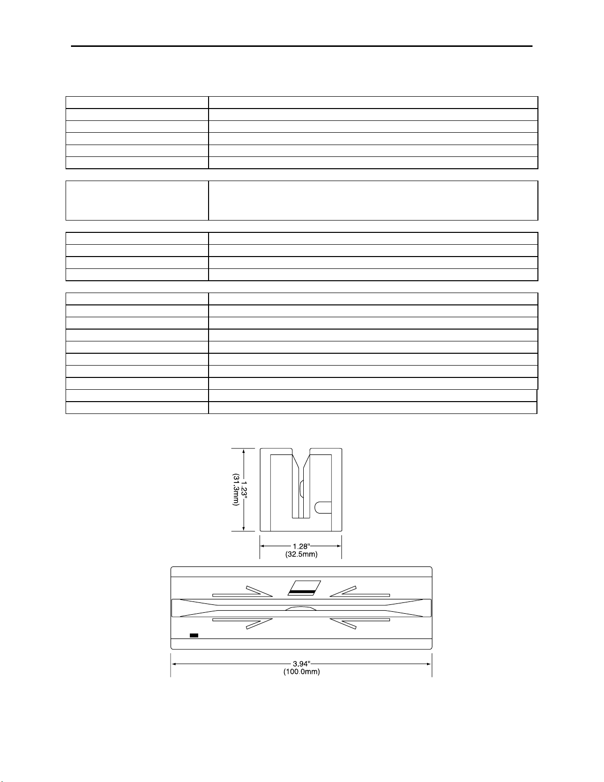
Section 1. Features and Specifications
Table 1-2. Specifications
Reference Standards ISO 7810 and ISO 7811/CDL/ AAMVA*
Power Input 5V From USB port
Recording Method Two-frequency coherent phase (F2F)
Message Format ASCII
Card Speed 3 to 50 IPS
MTBF Electronics: 125,000 hours. Head: 1,000,000 passes
ELECTRICAL
Current
Normal Mode
Suspend Mode
Weight 4.5 oz. (127.57 g)
Cable length 6ft.
Connector USB Type A plug
Temperature
Operating 32oF to 131oF (0oC to 55oC)
Storage -22oF to 158oF (-30oC to 70oC)
Humidity
Operating 10% to 90% noncondensing
Storage Up to 100% noncondensing
Altitude
Operating 0-10,000 ft. (0-3048 m.)
Storage 0-50,000 ft. (0-15240 m.)
30mA
300uA
MECHANICAL (STANDARD PRODUCT)
ENVIRONMENTAL
* ISO (International Standards Organization), CDL (California Drivers License), and AAMVA (American
Association of Motor Vehicle Administrators).
Figure 1-2. Dimensions
3
Page 73

USB Swipe Reader
4
Page 74
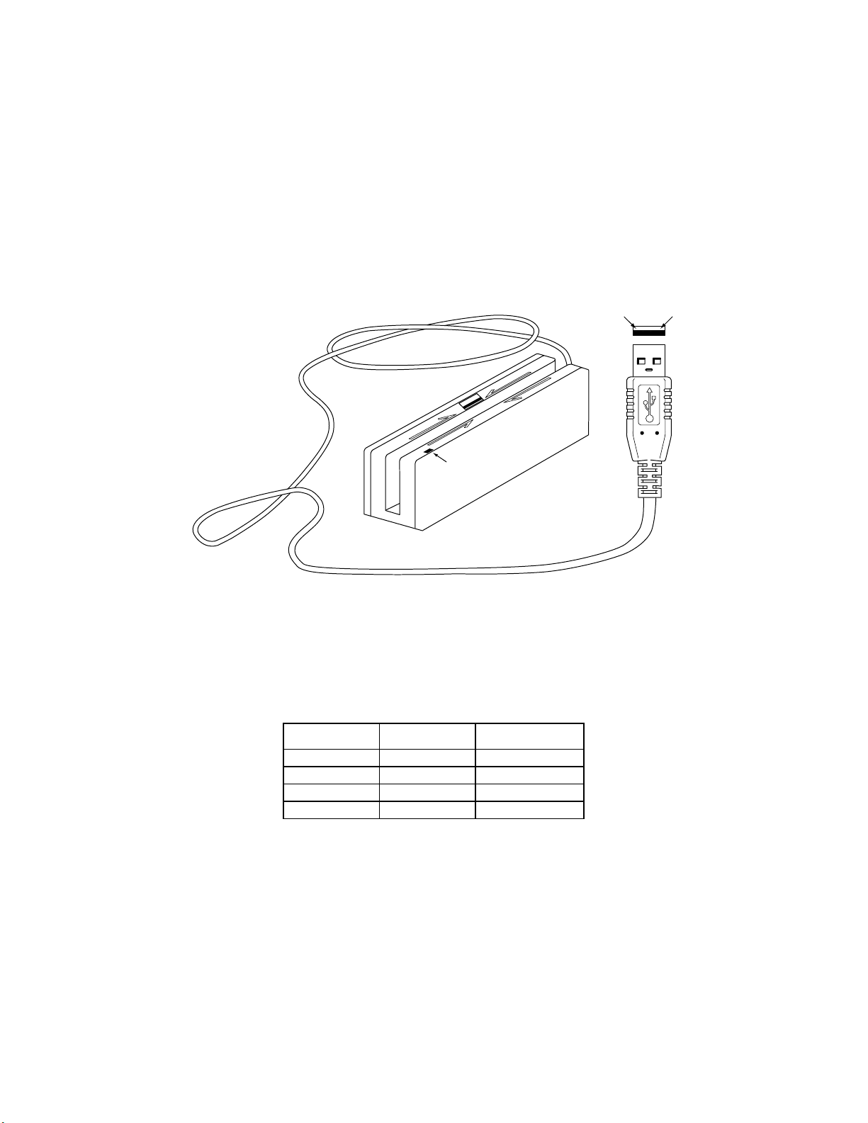
SECTION 2. INSTALLATION
This section describes the cable connection, the Windows Plug and Play Setup, and the physical
mounting of the unit.
USB CONNECTION
Connect the USB cable to a USB port on the host. The Reader, LED Indicator, and pin numbers
for the 4-pin connector are shown in Figure 2-1.
14
LED Indicator
Figure 2-1. Reader Cable and Connector
Pin numbers and signal descriptions for the cable shown in the illustration are listed in
Table 1-1.
Table 2-1. 4-Pin Connector
Pin Number Signal Cable Color
1 VCC Red
2 - Data White
3 +Data Green
4 Ground Black
5
Page 75

USB Swipe Reader
WINDOWS PLUG AND PLAY SETUP
On hosts with the Windows operating system, the first time the device is plugged into a specific
USB port, Windows will pop up a dialog box, which will guide you through the process of
installing a device driver for the device. After this process is completed once, Windows will no
longer request this process as long as the device is plugged into the same USB port. The device
driver that Windows will install for this device is the driver used for HID devices and it is part of
the Windows operating system. When the dialog box pops up, follow the instructions given to
you in the dialog box. Sometimes Windows will find all the files it needs on its own without
giving you any prompts. Other times Windows will need to know the location of the files it
needs. If Windows prompts you for the file locations, insert the CD that was used to install
Windows on your PC and point Windows to the root directory of the CD. Windows should find
all the files it needs there.
MOUNTING
The Reader may be mounted with screws or fastening tape as described below.
Caution
The Reader should be mounted such that the bottom (mounting
side) is not exposed to the user. This is because the mounting side
of the reader may be susceptible to electrostatic discharge.
1. The Reader can be mounted on a surface in three ways:
• By two screws through the surface attached to the bottom of the unit and running
the cable on the top of the surface;
• By two screws through the surface attached to the bottom of the unit and by
drilling a hole in the surface for the cable and running the cable through the hole;
• By attaching the unit to the surface with fastening tape and running the cable on
the top of the surface.
Note
The two mounting inserts are 3 mm diameter; 0.5 mm pitch; 6.4
mm deep. The length of the screws used depends on the mounting
surface thickness and the thickness of washers (if used).
The mounting dimensions are shown in Figure 2-2. Determine the method of mounting
required.
6
Page 76

Section 2. Installation
Figure 2-2. Mounting Hole Dimensions For Surface
2. Ensure the Reader is positioned on a flat, accessible surface with at least 4 inches
clearance on either end for room to swipe a card. Orient the Reader so the side with the
LED is facing the direction of intended use.
If fastening tape is to be used, clean the area that the Reader will be mounted on with
isopropyl alcohol. Remove the adhesive protective cover on the fastening tape, and
position the Reader and push down firmly.
3. Mount the Reader.
7
Page 77

USB Swipe Reader
8
Page 78

SECTION 3. OPERATION
This section describes the LED Indicator and Card Read.
LED INDICATOR
The LED indicator will be either off, red, or green. When the device is not powered, the LED
will be off. When the device is first plugged in, the LED will be red. As soon as the device is
plugged in, the host will try to enumerate the device. Once the device is enumerated the LED
will turn green indicating that the device is ready for use. When a card is being swiped, the LED
will turn off temporarily until the swipe is completed. If there are no errors decoding the card
data then the LED will turn green. If there are any errors decoding the card data, the LED will
turn red for approximately two seconds to indicate that an error occurred and then turn green.
Anytime the host puts the device into suspend mode, the LED will turn off. Once the host takes
the device out of suspend mode, the LED will return to the state it was in prior to entering
suspend mode.
CARD READ
A card may be swiped through the Reader slot when the LED is green. The magnetic stripe must
face toward the front (the side with the LED) and may be swiped in either direction. If there is
data encoded on the card, the device will attempt to decode the data and then send the results to
the host via a USB HID input report. After the results are sent to the host, the device will be
ready to read the next card.
9
Page 79

USB Swipe Reader
10
Page 80

SECTION 4. USB COMMUNICATIONS
This device conforms to the USB specification revision 1.1. This device also conforms with the
Human Interface Device (HID) class specification version 1.1. The device communicates to the
host as a vendor defined HID device. The details about how the card data and commands are
structured into HID reports follow later in this section. The latest versions of the Windows
operating systems, Windows 98, Me, and 2000, all come with a standard Windows USB HID
driver. Windows applications that communicate to this device can be easily developed. These
applications can communicate to the device using standard windows API calls that communicate
to the device using the standard Windows USB HID driver. These applications can be easily
developed using compilers such as Microsoft’s Visual Basic or Visual C++. A demonstration
program and its source code, written in Visual Basic, that communicates with this device is
available. This demo program can be used to test the device and it can be used as a guide for
developing other applications. More details about the demo program follow later in this
document.
It is strongly recommended that application software developers become familiar with the HID
specification the USB specification before attempting to communicate with this device. This
document assumes that the reader is familiar with these specifications. These specifications can
be downloaded free from www.usb.org
This is a full speed USB device. This device has a number of programmable configuration
properties. These properties are stored in non-volatile EEPROM memory. These properties can
be configured at the factory or by the end user. The device has an adjustable endpoint descriptor
polling interval value that can be set to any value in the range of 1ms to 255ms. This property
can be used to speed up or slow down the card data transfer rate. The device also has an
adjustable serial number descriptor. More details about these properties can be found later in this
document in the command section.
.
The device will go into suspend mode when directed to do so by the host. The device will
wakeup from suspend mode when directed to do so by the host. The device does not support
remote wakeup.
This device is powered from the USB bus. Its vendor ID is 0x0801 and its product ID is 0x0002.
HID USAGES
HID devices send data in reports. Elements of data in a report are identified by unique identifiers
called usages. The structure of the device’s reports and the device’s capabilities are reported to
the host in a report descriptor. The host usually gets the report descriptor only once, right after
the device is plugged in. The report descriptor usages identify the devices capabilities and report
structures. For example, a device could be identified as a keyboard by analyzing the device’s
report descriptor. Usages are four byte integers. The most significant two bytes are called the
usage page and the least significant two bytes are called usage IDs. Usages that are related can
share a common usage page. Usages can be standardized or they can be vendor defined.
Standardized usages such as usages for mice and keyboards can be found in the HID Usage
Tables document and can be downloaded free at www.usb.org
have a usage page in the range 0xff00 – 0xffff. All usages for this device use vendor defined
magnetic stripe reader usage page 0xff00. The usage IDs for this device are defined in the
. Vendor defined usages must
11
Page 81

USB Swipe Reader
following table. The usage types are also listed. These usage types are defined in the HID
Usage Tables document.
Magnetic Stripe Reader usage page 0xff00:
Usage ID
(Hex)
1 Decoding reader device Collection None
20 Track 1 decode status Data Input
21 Track 2 decode status Data Input
22 Track 3 decode status Data Input
28 Track 1 data length Data Input
29 Track 2 data length Data Input
2A Track 3 data length Data Input
30 Track 1 data Data Input
31 Track 2 data Data Input
32 Track 3 data Data Input
38 Card encode type Data Input
20 Command message Data Feature
Usage Name Usage
Type
Report
Type
REPORT DESCRIPTOR
The HID report descriptor is structured as follows:
Item Value(Hex)
Usage Page (Magnetic Stripe
Reader)
Usage (Decoding reader device) 09 01
Collection (Application) A1 01
Logical Minimum (0) 15 00
Logical Maximum (255) 26 ff 00
Report Size (8) 75 08
Usage (Track 1 decode status) 09 20
Usage (Track 2 decode status) 09 21
Usage (Track 3 decode status) 09 22
Usage (Track 1 data length) 09 28
Usage (Track 2 data length) 09 29
Usage (Track 3 data length) 09 2A
(Continued)
06 00 FF
12
Page 82

Section 4. USB Communications
Item Value(Hex)
Usage (Card encode type) 09 38
Report Count (7) 95 07
Input (Data, Variable, Absolute, Bit
Field)
Usage (Track 1 data) 09 30
Report Count (110) 95 6E
Input (Data, Variable, Absolute,
Buffered Bytes)
Usage (Track 2 data) 09 31
Report Count (110) 95 6E
Input (Data, Variable, Absolute,
Buffered Bytes)
Usage (Track 3 data) 09 32
Report Count (110) 95 6E
Input (Data, Variable, Absolute,
Buffered Bytes)
Usage (Command message) 09 20
Report Count (24) 95 18
Feature (Data, Variable, Absolute,
Buffered Bytes)
End Collection C0
81 02
82 02 01
82 02 01
82 02 01
B2 02 01
CARD DATA
Card data is only sent to the host on the Interrupt In pipe using an Input Report. The device will
send only one Input Report per card swipe. If the host requests data from the device when no
data is available, the device will send a Nak to the host to indicate that it has nothing to send.
When a card is swiped, the Input Report will be sent even if the data is not decodable. The
following table shows how the input report is structured.
Offset Usage Name
0 Track 1 decode status
1 Track 2 decode status
2 Track 3 decode status
3 Track 1 data length
4 Track 2 data length
5 Track 3 data length
6 Card encode type
7 – 116 Track 1 data
117 – 226 Track 2 data
227 - 336 Track 3 data
13
Page 83

USB Swipe Reader
TRACK 1 DECODE STATUS
Bits 7-1 0
Value Reserved Error
This is a one-byte value, which indicates the status of decoding track 1. Bit position zero
indicates there was an error decoding track 1 if the bit is set to 1. If it is zero, then no error
occurred. If a track has data on it that is not noise, and it is not decodable, then a decode error is
indicated. If a decode error is indicated, the corresponding track data length value for the track
that has the error will be set to zero and no valid track data will be supplied.
TRACK 2 DECODE STATUS
Bits 7-1 0
Value Reserved Error
This is a one-byte value, which indicates the status of decoding track 2. Bit position zero
indicates if there was an error decoding track 2 if this bit is set to one. If it is zero, then no error
occurred. If a track has data on it that is not noise, and it is not decodable, then a decode error is
indicated. If a decode error is indicated, the corresponding track data length value for the track
that has the error will be set to zero and no valid track data will be supplied.
TRACK 3 DECODE STATUS
Bits 7-1 0
Value Reserved Error
This is a one-byte value, which indicates the status of decoding track 3. Bit position zero
indicates there was an error decoding track 3 if this bit is set to one. If it is zero, then no error
occurred. If a track has data on it that is not noise, and it is not decodable, then a decode error is
indicated. If a decode error is indicated, the corresponding track data length value for the track
that has the error will be set to zero and no valid track data will be supplied.
TRACK 1 DATA LENGTH
This one byte value indicates how many bytes of decoded card data are in the track 1 data field.
This value will be zero if there was no data on the track or if there was an error decoding the
track.
TRACK 2 DATA LENGTH
This one byte value indicates how many bytes of decoded card data are in the track 2 data field.
This value will be zero if there was no data on the track or if there was an error decoding the
track.
TRACK 3 DATA LENGTH
This one byte value indicates how many bytes of decoded card data are in the track 3 data field.
This value will be zero if there was no data on the track or if there was an error decoding the
track.
14
Page 84

Section 4. USB Communications
CARD ENCODE TYPE
This one byte value indicates the type of encoding that was found on the card. The following
table defines the possible values.
Value Encode Type Description
0 ISO/ABA ISO/ABA encode format
1 AAMVA AAMVA encode format
2 CADL CADL encode format
3 Blank The card is blank.
4 Other The card has a non-standard encode format. For example,
ISO/ABA track 1 format on track 2.
5 Undetermined The card encode type could not be determined because no
tracks could be decoded.
6 None No decode has occurred. This type occurs if no magnetic stripe
data has been acquired since the data has been cleared or
since the device was powered on. This device only sends an
Input report when a card has been swiped so this value will
never occur.
TRACK DATA
If decodable track data exits for a given track, it is located in the track data field that corresponds
to the track number. The length of each track data field is fixed at 110 bytes, but the length of
valid data in each field is determined by the track data length field that corresponds to the track
number. Track data located in positions greater that the track data length field indicates are
undefined and should be ignored. The HID specification requires that reports be fixed in size,
but the number of bytes encoded on a card may vary. Therefore, the Input Report always
contains the maximum amount of bytes that can be encoded on the card and the number of valid
bytes in each track is indicated by the track data length field. The track data is decoded and
converted to ASCII. The track data includes all data starting with the start sentinel and ending
with the end sentinel.
TRACK 1 DATA
This field contains the decoded track data for track 1.
TRACK 2 DATA
This field contains the decoded track data for track 2.
TRACK 3 DATA
This field contains the decoded track data for track 3.
15
Page 85

USB Swipe Reader
COMMANDS
Most host applications do not need to send commands to the device. Most host applications
only need to obtain card data from the device as described previously in this section. This
section of the manual can be ignored by anyone who does not need to send commands to the
device.
Command requests and responses are sent to and received from the device using feature reports.
Command requests are sent to the device using the HID class specific request Set_Report. The
response to a command is retrieved from the device using the HID class specific request
Get_Report. These requests are sent over the default control pipe. When a command request is
sent, the device will Nak the Status stage of the Set_Report request until the command is
completed. This insures that as soon as the Set_Report request is completed, the Get_Report
request can be sent to get the command response. The usage ID for the command message was
shown previously in the Usage Table.
The following table shows how the feature report is structured for command requests:
Offset Field Name
0 Command Number
1 Data Length
2 – 23 Data
The following table shows how the feature report is structured for command responses.
Offset Field Name
0 Result Code
1 Data Length
2 – 23 Data
COMMAND NUMBER
This one byte field contains the value of the requested command number. The following table
lists all the existing commands.
Value Command Number Description
0 GET_PROPERTY Sets a property in the device
1 SET_PROPERTY Gets a property from the device
DATA LENGTH
This one byte field contains the length of the valid data contained in the Data field.
DATA
This multi-byte field contains command data if any. Note that the length of this field is fixed at
22 bytes. Valid data should be placed in the field starting at offset 2. Any remaining data after
the valid data should be set to zero. This entire field must always be set even if there is no valid
data. The HID specification requires that Reports be fixed in length. Command data may vary
in length. Therefore, the Report should be filled with zeros after the valid data.
16
Page 86

Section 4. USB Communications
RESULT CODE
This one byte field contains the value of the result code. There are two types of result codes:
generic result codes and command specific result codes. Generic result codes always have the
most significant bit set to zero. Generic result codes have the same meaning for all commands
and can be used by any command. Command specific result codes always have the most
significant bit set to one. Command specific result codes are defined by the command that uses
them. The same code can have different meanings for different commands. Command specific
result codes are defined in the documentation for the command that uses them. Generic result
codes are defined in the following table.
Value Result Code Description
0 SUCCESS The command completed successfully.
1 FAILURE The command failed.
2 BAD_PARAMETER The command failed due to a bad
parameter or command syntax error.
GET AND SET PROPERTY COMMANDS
The Get Property command gets a property from the device. The Get Property command
number is 0.
The Set Property command sets a property in the device. The Set Property command number
is 1.
The Get and Set Property command data fields for the requests and responses are structured as
follows:
Get Property Request Data:
Data Offset Value
0 Property ID
Get Property Response Data:
Data Offset Value
0 – n Property Value
Set Property Request Data:
Data Offset Value
0 Property ID
1 – n Property Value
Set Property Response Data:
None
The result codes for the Get and Set Property commands can be any of the codes list in the
generic result code table.
17
Page 87

USB Swipe Reader
Property ID is a one byte field that contains a value that identifies the property. The following
table lists all the current property ID values:
Value Property ID Description
0 SOFTWARE_ID The device’s software identifier
1 SERIAL_NUM The device’s serial number
2 POLLING_INTERVAL The interrupt pipe’s polling interval
The Property Value is a multiple byte field that contains the value of the property. The number
of bytes in this field depends on the type of property and the length of the property. The
following table lists all of the property types and describes them.
Property Type Description
Byte This is a one byte value. The valid values depend on the property.
String This is a multiple byte ASCII string. Its length can be zero to a
maximum length that depends on the property. The value and
length of the string does not include a terminating NUL character.
SOFTWARE_ID PROPERTY
Property ID: 0
Property Type: String
Length: Fixed at 11 bytes
Get Property: Yes
Set Property: No
Description: This is an 11 byte read only property that identifies the software part
number and version for the device. The first 8 bytes represent the part number and the last 3
bytes represent the version. For example this string might be “21042804A02”. Examples
follow:
Example Get SOFTWARE_ID property Request (Hex):
Cmd Num Data Len Prp ID
00 01 00
Example Get SOFTWARE_ID property Response (Hex):
Result Code Data Len Prp Value
00 01 32 31 30 34 32 38 30 34 41 30 32
18
Page 88

Section 4. USB Communications
SERIAL_NUM PROPERTY
Property ID: 1
Property Type: String
Length: 0 – 15 bytes
Get Property: Yes
Set Property: Yes
Default Value: The default value is no string with a length of zero.
Description: The value is an ASCII string that represents the device’s serial number.
This string can be 0 – 15 bytes long. This property is stored in non-volatile EEPROM memory
so it will not change when the unit is power cycled. The value of this property, if any, will be
sent to the host when the host requests the USB string descriptor. When this property is
changed, the unit must be power cycled to have these changes take effect for the USB descriptor.
If a value other than the default value is desired, it can be set by the factory upon request.
Examples follow.
Example Set SERIAL_NUM property Request (Hex):
Cmd Num Data Len Prp ID Prp Value
01 04 01 31 32 33
Example Set SERIAL_NUM property Response (Hex):
Result Code Data Len Data
00 00
Example Get SERIAL_NUM property Request (Hex):
Cmd Num Data Len Prp ID
00 01 01
Example Get SERIAL_NUM property Response (Hex):
Result Code Data Len Prp Value
00 03 31 32 33
POLLING_INTERVAL PROPERTY
Property ID: 2
Property Type: Byte
Length: 1 byte
Get Property: Yes
Set Property: Yes
Default Value: 10
Description: The value is a byte that represents the devices polling interval for the
Interrupt In Endpoint. The value can be set in the range of 1 – 255 and has units of milliseconds.
The polling interval tells the host how often to poll the device for card data packets. For
example, if the polling interval is set to 10, the host will poll the device for card data packets
every 10ms. This property can be used to speed up or slow down the time it takes to send card
data to the host. The trade-off is that speeding up the card data transfer rate increases the USB
bus bandwidth used by the device, and slowing down the card data transfer rate decreases the
USB bus bandwidth used by the device. This property is stored in non-volatile EEPROM
memory so it will not change when the unit is power cycled. The value of this property, if any,
19
Page 89

USB Swipe Reader
will be sent to the host when the host requests the device’s USB endpoint descriptor. When this
property is changed, the unit must be power cycled to have these changes take effect for the USB
descriptor. If a value other than the default value is desired, it can be set by the factory upon
request. Examples follow:
Example Set POLLING_INTERVAL property Request (Hex):
Cmd Num Data Len Prp ID Prp Value
01 02 02 0A
Example Set POLLING_INTERVAL property Response (Hex):
Result Code Data Len Data
00 00
Example Get POLLING_INTERVAL property Request (Hex):
Cmd Num Data Len Prp ID
00 01 02
Example Get POLLING_INTERVAL property Response (Hex):
Result Code Data Len Prp Value
00 01 0A
20
Page 90

SECTION 5. DEMO PROGRAM
The demo program, which is written in Visual Basic, can be used to do the following:
• Read cards from the device and view the card data
• Send command requests to the device and view the command responses
• Guide application developers in their application development by providing examples, in
source code, of how to properly communicate with the device using the standard Windows
APIs
The part numbers for the demo program can be found in this document in Section 1 under
Accessories.
INSTALLATION
To install the demo program, run the setup.exe file and follow the instructions given on the
screen.
OPERATION
To operate the demo program perform the following steps:
• Plug the device into a USB port on the host
• If this is the first time the device has been plugged into the host, then follow the instructions
on the screen for installing the Windows HID device driver. This is explained in more detail
in the installation section of this document.
• Run the demo program.
• To read cards and view the card data, click on the Read Cards button and swipe a card when
prompted to do so.
• When finished reading cards, close the dialog box.
• To send commands to the device, click on the send commands button.
• Enter a command in the Message edit box. All data entered should be in hexadecimal bytes
with a space between each byte. Enter the command number followed by the command data
if there is any. The application will automatically calculate and send the command data
length for you. For example, to send the GET_PROPERTY command for property
SOFTWARE_ID enter 00 00.
• Press Enter or click on Send message to send the command and receive the result.
• The command request and the command result will be displayed in the Communications
Dialog edit box.
• The Clear Dialog button clears the Communication Dialog edit box.
21
Page 91

USB Swipe Reader
SOURCE CODE
Source code is included with the demo program. It can be used as a guide for application
development. It is described in detail, with comments, to assist developers. The book USB
Complete by Jan Axelson is also a good guide for application developers, especially the chapter
on Human Interface Device Host Applications (see “Reference Documents” in Section 1).
22
Page 92

MAGTEK DEVICE DRIVERS
FOR WINDOWS
PROGRAMMING REFERENCE MANUAL
Manual Part Number: 99875125 Rev 6
NOVEMBER 2001
20725 South Annalee Avenue
Carson, CA 90746
Phone: (310) 631-8602
FAX: (310) 631-3956
Technical Support: (888) 624-8350
www.MagTek.com
Page 93

Copyright 1996-2001
MAG-TEK, Inc.
Printed in the United States of America
Information in this document is subject to change without notice. No part of this document may
be reproduced or transmitted in any form or by any means, electronic or mechanical, for any
purpose, without the express written permission of Mag-Tek, Inc.
MagTek is a registered trademark of Mag-Tek, Inc.
Microsoft, MS, MSDOS, MSCOMM and Microsoft Visual Basic are registered trademarks of
Microsoft Corporation; Windows and Windows 95 are trademarks of Microsoft Corporation.
REVISIONS
Rev
Number
1 20 Nov 98 Initial Release
2 16 Feb 99 Sec 1: Editorial comments for clarification; Sec 2: Added c_wr_secure
3 27 Apr 99 Global: Changed names of Mt-211 and MT-215 to port powered
4 21 Oct 99 Sec 1: added: part numbers of media, special commands, MICR
5 14 Dec 99 Appendix A: Added statement about "Long File Names" under "Adding
630Nov 01 Editorial changes throughout and added Software Version MTD 1.10,
Date Notes
and trks 1, 2, and 3; Sec 3: Editorial comments for clarification;
Appendix A: Added MT-85 and clarified tables; Appendix D: Added
c_wr_secure and tks 1, 2, and 3 and MT-85 Encoder sheet.
readers; Sec 3: Added card insertion note to event; Sec 4: Added this
section, Data Parsing. Appendix A: Changed file names. Appendix D.
Changed names.
material; Sec 2: changed properties table; Sec 3: added errors 45 and
60 to write command; Sec 4: added descriptions to language format;
updated default formats; Sec 5: replaced Visual Basic example;
Appendix A; Completely revised; Appendix D: added applied_fmt to all
forms.
MagTek Device Drivers" General Notes number 4; added statement to
"Completing the Installation" about sharing a single port; Edited
"Removing the Drivers"; added "Configuration Examples of NT Drivers."
Appendix D: Under IntelliPIN PINPad and MSR, added statement under
Remarks about IntelliPIN driver; under MiniWedge MSR added
statement about ASCII and Character Conversion.
which includes Windows ME/2000/XP.
ii
Page 94

Limited Warranty
Mag-Tek, Inc. (hereinafter “Mag-Tek”) warrants this Mag-Tek product IN ITS ENTIRETY, to be in good
working order for a period of 90 days from the date of purchase from Mag-Tek. Should this product fail
to be in good working order at any time during this warranty period, Mag-Tek will, at its option, repair or
replace this product at no additional charge except as set forth below. Repair parts and replacement
products will be furnished on an exchange basis and will be either reconditioned or new. All replaced
parts and products become the property of Mag-Tek. This limited warranty does not include service to
repair damage to the product resulting from accident, disaster, misuse, abuse, or non-Mag-Tek
modification of the product.
Limited Warranty service may be obtained by delivering the product during the warranty period to MagTek (20725 S. Annalee Ave., Carson, CA 90746). If this product is delivered by mail, you agree to insure
the product or assume the risk of loss or damage in transit, to prepay shipping charges to the warranty
service location and to use the original shipping container or equivalent.
ALL EXPRESS AND IMPLIED WARRANTIES FOR THIS PRODUCT, INCLUDING THE
WARRANTIES OF MERCHANTABILITY AND FITNESS FOR A PARTICULAR PURPOSE, ARE
LIMITED IN DURATION TO A PERIOD OF 90 DAYS FROM THE DATE OF PURCHASE, AND
NO WARRANTIES, WHETHER EXPRESS OR IMPLIED, WILL APPLY AFTER THIS PERIOD,
EXCEPT AS PROVIDED IN THE PRECEDING SENTENCE. EACH PURCHASER UNDERSTANDS
THAT THE MAG-TEK PRODUCT IS OFFERED AS IS.
IF THIS PRODUCT IS NOT IN GOOD WORKING ORDER AS WARRANTED ABOVE, YOUR
SOLE REMEDY SHALL BE REPAIR OR REPLACEMENT AS PROVIDED ABOVE. IN NO EVENT
WILL MAG-TEK BE LIABLE TO YOU FOR ANY DAMAGES, INCLUDING ANY LOST PROFITS,
LOST SAVINGS OR OTHER INCIDENTAL OR CONSEQUENTIAL DAMAGES ARISING OUT OF
THE USE OF OR INABILITY TO USE SUCH PRODUCT, EVEN IF MAG-TEK HAS BEEN
ADVISED OF THE POSSIBILITY OF SUCH DAMAGES, OR FOR ANY CLAIM BY ANY OTHER
PARTY.
THIS WARRANTY GIVES YOU SPECIFIC LEGAL RIGHTS, AND YOU MAY ALSO HAVE
OTHER RIGHTS WHICH VARY FROM STATE TO STATE.
iii
Page 95

TABLE OF CONTENTS
SECTION 1. OVERVIEW ................................................................................................................1
PROBLEMS WITH CONTROLLING DEVICES ...........................................................................1
BENEFITS OF A CONTROL LANGUAGE AND DRIVER ...........................................................2
LANGUAGE OVERVIEW .............................................................................................................3
Properties.................................................................................................................................3
COMMANDS ................................................................................................................................4
TYPICAL OPERATION ................................................................................................................5
Open a device ..........................................................................................................................5
Query the device’s capabilities ................................................................................................5
Prepare the device for work.....................................................................................................5
Use the device .........................................................................................................................5
Close the device ......................................................................................................................6
METHODS OF ACCESSING THE DEVICE ................................................................................6
Obtaining access to the device................................................................................................6
Interacting with the device .......................................................................................................7
Releasing access to the device ...............................................................................................8
ERRORS AND ERROR PROCESSING ......................................................................................8
HANDLING SPECIAL COMMANDS............................................................................................9
FILE PROPERTIES .....................................................................................................................9
INSTALLATION..........................................................................................................................10
MICR Format Numbers..........................................................................................................10
SECTION 2. PROPERTIES ..........................................................................................................11
account_no ............................................................................................................................11
amount ...................................................................................................................................11
applied_fmt ............................................................................................................................11
c_card_stat ............................................................................................................................11
c_keypress.............................................................................................................................11
c_keystring .............................................................................................................................11
c_magnetic.............................................................................................................................11
c_mechanics ..........................................................................................................................11
c_pin.......................................................................................................................................11
c_smart ..................................................................................................................................11
c_tracks..................................................................................................................................11
c_write....................................................................................................................................12
c_wr_secure...........................................................................................................................12
capitalize ................................................................................................................................12
card_stat ................................................................................................................................12
chk_account ...........................................................................................................................12
chk_amount ...........................................................................................................................12
chk_bankid .............................................................................................................................12
chk_data ................................................................................................................................12
chk_format .............................................................................................................................12
chk_mod10 ............................................................................................................................12
chk_number ...........................................................................................................................12
chk_routing ............................................................................................................................12
chk_status ..............................................................................................................................12
chk_transit..............................................................................................................................12
cmd_pending .........................................................................................................................12
dblpinentry .............................................................................................................................12
dev_status..............................................................................................................................12
dev_version............................................................................................................................12
enable_cmc7..........................................................................................................................12
iv
Page 96

enc_key..................................................................................................................................13
enc_key_sn ............................................................................................................................13
enc_mode ..............................................................................................................................13
entry_echo .............................................................................................................................13
entry_len ................................................................................................................................13
entry_tout ...............................................................................................................................13
events_on ..............................................................................................................................13
invalcmdrsp ............................................................................................................................13
key_parity...............................................................................................................................13
lasterr .....................................................................................................................................13
max_pin_len...........................................................................................................................13
msg1 - msg4 ..........................................................................................................................13
oper_tout ................................................................................................................................14
pin_blk_fmt.............................................................................................................................14
pinfilldig ..................................................................................................................................14
port_name..............................................................................................................................14
pwroffdelay.............................................................................................................................14
s_down_tout...........................................................................................................................14
track1ss..................................................................................................................................14
trivpinchk ................................................................................................................................14
trk_enable ..............................................................................................................................14
trk1data ..................................................................................................................................14
trk2data ..................................................................................................................................14
trk3data ..................................................................................................................................14
visa_mac1 ..............................................................................................................................14
visa_mac2 ..............................................................................................................................14
visa_mac3 ..............................................................................................................................14
wr_coer ..................................................................................................................................14
wr_secure ..............................................................................................................................14
xact_type................................................................................................................................14
SECTION 3. COMMANDS............................................................................................................15
DATA FORMAT .........................................................................................................................15
RESPONSES .............................................................................................................................15
Notation Conventions.............................................................................................................16
COMMAND DESCRIPTIONS ....................................................................................................16
cancel.....................................................................................................................................16
display ....................................................................................................................................17
echo .......................................................................................................................................17
event ......................................................................................................................................18
get ..........................................................................................................................................18
load_key.................................................................................................................................19
rawrecv ..................................................................................................................................20
rawsend .................................................................................................................................21
rawxact...................................................................................................................................21
read ........................................................................................................................................22
Read Arguments .......................................................................................................................23
reset .......................................................................................................................................26
set ..........................................................................................................................................26
ver ..........................................................................................................................................26
write........................................................................................................................................27
SECTION 4. MAGNETIC CARD DATA PARSING ......................................................................29
GOALS .......................................................................................................................................29
ASSUMPTIONS .........................................................................................................................29
v
Page 97

DESCRIPTION...........................................................................................................................30
LANGUAGE FORMAT ...............................................................................................................31
Format Name .........................................................................................................................31
Format Template....................................................................................................................31
Format Rules .........................................................................................................................31
DEFAULT FORMATS ................................................................................................................35
EXAMPLE ..................................................................................................................................36
Retrieving properties from a magnetic card ...........................................................................36
SECTION 5. EXAMPLE APPLICATIONS ....................................................................................39
PROGRAMMING HINTS ...........................................................................................................39
VISUAL BASIC EXAMPLE.........................................................................................................39
C++ EXAMPLE ..........................................................................................................................45
POWER BUILDER EXAMPLE ...................................................................................................50
APPENDIX A. INSTALLATION AND SETUP ..............................................................................53
INSTALLING DEVICE DRIVERS (W95/98/ME) ........................................................................54
Adding the First Device Driver (W95/98/ME).........................................................................55
Adding Another Device Driver (W95/98/ME) .........................................................................55
Updating an Installed Device Driver (W95/98/ME) ................................................................56
Completing the Installation (W95/98/ME) ..............................................................................56
Modifying A Device Driver's Settings (W95/98/ME)...............................................................57
Removing The Drivers (W95/98/ME).....................................................................................59
INSTALLING DEVICE DRIVERS (WNT) ...................................................................................61
Installing the Driver Binaries (WNT) ......................................................................................62
Uninstalling the Drivers (WNT) ..............................................................................................62
INSTALLING DEVICE DRIVERS (W2000/XP) ..........................................................................63
Installing the Driver Binaries (W2000/XP) .............................................................................64
Uninstalling the Drivers (W2000/XP) .....................................................................................65
Uninstalling the Keyboard Hook Driver – (W2000/XP) ..........................................................65
WINDOWS NT/W2000/XP CONFIGURATION UTILITY ...........................................................66
Adding a Keyboard Device (WNT/2000/XP)..........................................................................66
Adding a Serial Device (WNT/W2000/XP).............................................................................67
Adding an ‘IntelliPIN MICR Aux’ Device (WNT/W2000/XP) ..................................................67
Viewing the List of Configured Devices (WNT/W2000/XP) ...................................................68
Using the MTCFG Utility (WNT/W2000/XP) ..........................................................................68
Command syntax summary ...................................................................................................69
Displaying Configuration Information (WNT/W2000/XP).......................................................69
Adding New Devices (WNT/W2000/XP) ................................................................................69
Configuration Examples of NT/W2000/XP ............................................................................71
Modifying a Device Driver's Settings (WNT/W2000/XP) .......................................................72
Removing a Device (WNT/W2000/XP)).................................................................................73
APPENDIX B. COMMAND LIST SUMMARY...............................................................................75
APPENDIX C. STATUS CODES ..................................................................................................77
APPENDIX D. DEVICE DRIVER SUMMARIES ...........................................................................79
INTELLIPIN PINPAD & MSR .....................................................................................................80
MAGWEDGE SWIPE READER.................................................................................................81
MINIWEDGE MSR .....................................................................................................................82
MICR+ CHECK READER & MSR..............................................................................................83
MINI MICR CHECK READER & MSR .......................................................................................84
PORT-POWERED RS-232 SWIPE READER ...........................................................................85
PORT-POWERED RS-232 INSERTION READER ...................................................................86
MT-85 LOCO ENCODER...........................................................................................................87
vi
Page 98

MT-95 HICO ENCODER ............................................................................................................88
INDEX.............................................................................................................................................89
FIGURES
Figure 1-1. MagTek Devices and Device Drivers for Windows.....................................................viii
Figure A-1. Properties Settings, Windows 95 ................................................................................58
Figure A-2. Advanced Settings, Windows 95 ................................................................................. 58
vii
Page 99

MTD
MagTek
Device Drivers
for Windows
viii
Figure 1-1. MagTek Devices and Device Drivers for Windows
Page 100

SECTION 1. OVERVIEW
The MagTek Device (MTD) Drivers for Windows is a collection of individual drivers that
support a number of MagTek products. These drivers provide a uniform application interface for
controlling a wide range of MagTek devices. The drivers, combined with a device control
language, solve many of the difficulties application developers face when attempting to control
hardware devices. The difficulties mount when faced with the task of developing an application
that supports an entire product line of devices.
Part Numbers for the MTD are as follows:
Part Number Windows Version Medium
30037385 All CD
99510030 9X/ME Internet* (MTD110-9x-ME)
99510031 NT (MTD110-NT)
99510032 2000/XP (MTD110-2K-XP)
*www.magtek.com
PROBLEMS WITH CONTROLLING DEVICES
The major problems with developing an application that supports an entire product line of
devices are as follows:
• Each MagTek device has a unique set of commands. The commands usually perform
similar functions on a particular class of devices but either differ in syntax or have small
variations in their functionality. An application would have to implement a custom
mechanism to control each device it supported–much like DOS applications had to do to
support various printers.
• Most MagTek devices communicate via data streams, not packets. This means that an
application receives data from the device one character at a time; it only receives partial
command responses. It would be the application’s responsibility to collect the incoming
data and parse it into individual responses.
• Responses from MagTek devices are inherently asynchronous. When an application
sends a command that requires a response, the response from the device arrives (or
worse, begins to arrive) long after the command is sent. The application would have to
either poll the device until all of the response is collected or implement a callback
mechanism to collect and receive it.
• Most MagTek devices maintain a communication protocol of some kind. In addition to
this, the protocols differ between devices. For example, some devices frame responses
with STX and ETX control characters and others simply use a CR or require a checksum
in the frame. To deal with this, an application would have to recognize and implement all
of the various protocols for the devices it supports.
1
 Loading...