

Page 1
ModularFlatPanel
Mountingand
Environments
Guide
CARROLLTOUCH
TOUCHPRODUCTS
ancompanyAMP
Page 2
Modular Flat
Modular Flat
Panel Mounting
Panel Mounting
and Environments
and Environments
Guide
Guide
CARROLL TOUCH
TOUCH PRODUCTS
an AMP company
November 1996
Page 3

Copyright
Copyright ©1996 Carroll Touch. All rights reserved.
Disclaimer
Carroll Touch has a policy of continually improving products as new
technology becomes available. Carroll Touch reserves the right to make
changes and improvements to the specifications of this equipment at any
time without notice.
Carroll Touch has made every attempt to ensure that the information in
this document is accurate and complete. Carroll Touch assumes no
liability for any damages that result from the use of this manual or the
equipment it documents. Carroll Touch reserves the right to make
changes to this document at any time without notice.
Trademarks
All brand and product names are trademarks or registered trademarks of
their respective holders.
Page 4

CARROLL TOUCH Table of Contents
Table of Contents
Welcome . . . . . . . . . . . . . . . . . . . . . . . . . . . . . . . . . . . . iii
Purpose . . . . . . . . . . . . . . . . . . . . . . . . . . . . . . . . . . . . . . . . iii
Audience . . . . . . . . . . . . . . . . . . . . . . . . . . . . . . . . . . . . . . . iv
Organization . . . . . . . . . . . . . . . . . . . . . . . . . . . . . . . . . . . . iv
Conventions. . . . . . . . . . . . . . . . . . . . . . . . . . . . . . . . . . . . . iv
1. Introduction . . . . . . . . . . . . . . . . . . . . . . . . . . . . . . 1-1
Technological Overview . . . . . . . . . . . . . . . . . . . . . . . . . . 1-2
Environmental Factors. . . . . . . . . . . . . . . . . . . . . . . . . . . . 1-3
Temperature. . . . . . . . . . . . . . . . . . . . . . . . . . . . . . . . . 1-3
Shock and Vibration . . . . . . . . . . . . . . . . . . . . . . . . . . 1-4
Chemicals . . . . . . . . . . . . . . . . . . . . . . . . . . . . . . . . . . 1-4
Moisture. . . . . . . . . . . . . . . . . . . . . . . . . . . . . . . . . . . . 1-4
Ambient Light . . . . . . . . . . . . . . . . . . . . . . . . . . . . . . . 1-5
Particulates. . . . . . . . . . . . . . . . . . . . . . . . . . . . . . . . . . 1-6
Application Environments. . . . . . . . . . . . . . . . . . . . . . . . . 1-6
2. Mounting Techniques . . . . . . . . . . . . . . . . . . . . . . 2-1
Simplest Mounting Method. . . . . . . . . . . . . . . . . . . . . . . . 2-2
Typical NEMA4 Mounting Method . . . . . . . . . . . . . . . . . 2-3
Anti-Shock/Vibration Mounting Method . . . . . . . . . . . . . 2-5
Industrial or Medical Mounting Method . . . . . . . . . . . . . . 2-6
3. Bezel/Filter Assembly . . . . . . . . . . . . . . . . . . . . . . . 3-1
Component Materials . . . . . . . . . . . . . . . . . . . . . . . . . . . . 3-2
Polycarbonate Chemical Resistance . . . . . . . . . . . . . . . . . 3-2
4. Sealing and Coating . . . . . . . . . . . . . . . . . . . . . . . . 4-1
Sealing. . . . . . . . . . . . . . . . . . . . . . . . . . . . . . . . . . . . . . . . 4-2
Coating. . . . . . . . . . . . . . . . . . . . . . . . . . . . . . . . . . . . . . . . 4-3
Glossary . . . . . . . . . . . . . . . . . . . . . . . . . . . . . . . . . . .GL-1
Index. . . . . . . . . . . . . . . . . . . . . . . . . . . . . . . . . . . . . . IN-1
i
Page 5

Table of Contents CARROLL TOUCH
List of Figures
Figure 1-1. Scanning Infrared Technology . . . . . . . . . . . . . . . . . . 1-2
Figure 1-2. Modular Flat Panel Touch System Components . . . . 1-3
Figure 1-3. Mounting to Prevent Moisture Accumulation . . . . . . 1-5
Figure 2-1. Simplest Mounting Method (Front View) . . . . . . . . . 2-2
Figure 2-2. Simplest Mounting Method (Side View) . . . . . . . . . . 2-3
Figure 2-3. Typical NEMA4 Mounting Method (Front View) . . 2-4
Figure 2-4. Typical NEMA4 Mounting Method (Side View) . . . 2-5
Figure 2-5. Anti-Shock/Vibration Mounting Method . . . . . . . . . 2-6
Figure 2-6. Industrial or Medical Mounting Method . . . . . . . . . . 2-7
Figure 4-1. Modular Flat Panel Touch System Sealing . . . . . . . . 4-2
List of Tables
Table 1-1. Environmental Light Strengths . . . . . . . . . . . . . . . . . . 1-5
Table 1-2. Application/Operating Environments . . . . . . . . . . . . . 1-6
Table 3-1. Effects of Chemical Classes on Polycarbonates . . . . . 3-3
ii
Page 6

WelcomeWelcome
A
s computers become a part of daily life, a technology that makes
them easier to use has become a necessity. Carroll Touch provides
the solution through the power of touch.
Because pointing or touching is a natural means of indicating choice,
touch systems are ideal for selection-based applications where
easy-to-follow menus guide a user through a series of steps or choices.
Touch is well accepted by the casual user because its simple, natural
interface hides the complexity of computer systems.
Purpose
The modular flat panel touch system is especially well-suited to rugged
environments, such as industrial settings where exposure to chemicals
is likely, medical settings where the system must be scrubbed after
every use, and public settings (such as kiosks) that subject the system
to repeated, possibly abusive use.
Thank you for your interest in Carroll Touch products!
This guide explains the operation of a scanning infrared (IR) touch
system and reviews the types of mounting, sealing and coating
techniques to adapt an IR touch system to various environmental and
chemical factors.
Modular Flat Panel Mounting and Environments Guide iii
Page 7

Welcome CARROLL TOUCH
Audience
This guide is intended for analysts who need to determine how to use
and/or adapt an infrared scanning touch system to the needs of their
particular application.
Organization
Chapter 1, “Introduction,” contains a brief technological overview of
the ways in which scanning infrared touch systems function. The
chapter goes on to list environmental factors affecting touch, such as
temperature, ambient light, chemicals, particulate contaminants,
moisture, shock and vibration.
Chapter 2, “Flat Panel Mounting Techniques,” illustrates four separate
mounting schemes, each of which is designed to increase the
functionality of the touch system in reaction to a different environment.
The mounting methods include simple, typical NEMA/4,
anti-shock/vibration, and industrial/medical.
Conventions
Chapter 3, “Bezel/Filter Assembly,” shows the modular flat panel bezel
and filter and its standard manufacturing material, along with its
chemical properties.
Chapter 4, “Sealing and Coating,” discusses the concept of sealing,
along with an explanation of how to seal the modular flat panel touch
system. The concept of coating and reasons for it are explained, along
with Carroll Touch conformal coating.
The Glossary defines terms that are unique or whose usage is unique to
touch.
For clarity, this guide uses certain conventions to visually distinguish
different types of information. The conventions are:
• Bold is used to emphasize a word or phrase, including definitions
of important concepts.
• Information of particular importance or actions that may have
undesirable results if performed improperly are included under the
headings
Note and Caution.
iv Modular Flat Panel Mounting and Environments Guide
Page 8

1
T
Introduction
Introduction
his chapter contains a brief technological overview of scanning
infrared touch systems and describes the environmental factors
that affect touch, such as temperature, shock and vibration, chemicals,
moisture, ambient light, and particulates. A brief analysis of the
environmental factors present in various locations is also included.
The topics covered include:
• Technological Overview.
• Environmental Factors.
• Application Environments.
Modular Flat Panel Mounting and Environments Guide 1-1
Page 9
Chapter 1 - Introduction CARROLL TOUCH
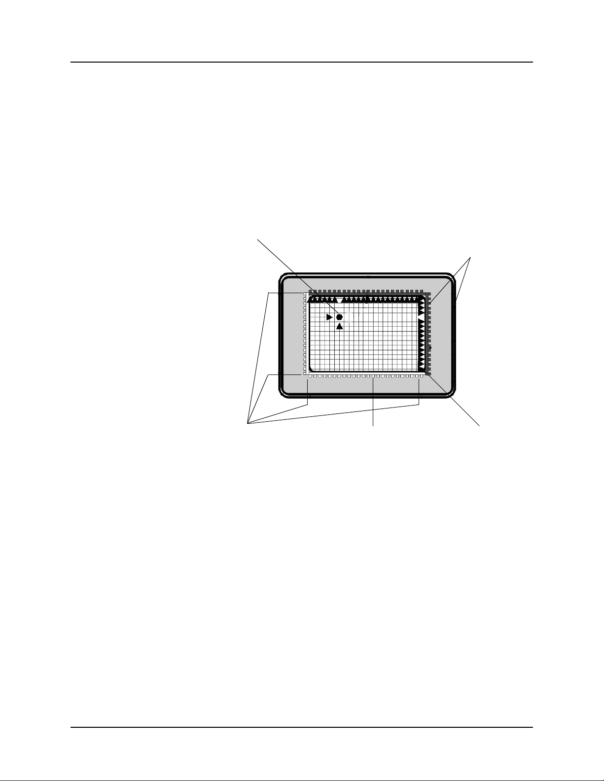
Technological Overview
The operation of all scanning infrared (IR) touch systems is based on
the creation of a grid of IR light beams above the viewing surface of a
CRT monitor or flat panel display and the recognition of the location at
which individual beams within the grid are interrupted. To create such
a grid, IR light emitting diodes (LEDs) are paired with phototransistors,
each set constituting an opto-pair or physical beam, to create a
horizontal (x-axis) and a vertical (y-axis) array of beams. The two
arrays of beams and their circuitry make up an opto-matrix frame, as
shown in Figure 1-1.
Touch Activation Inside and Outside Edges of
Infrared-Transparent Bezel
Grid of Infrared Light Opto-Matrix Frame
Inside Bezel
Edge of Active
Display Area
Figure 1-1. Scanning Infrared Technology
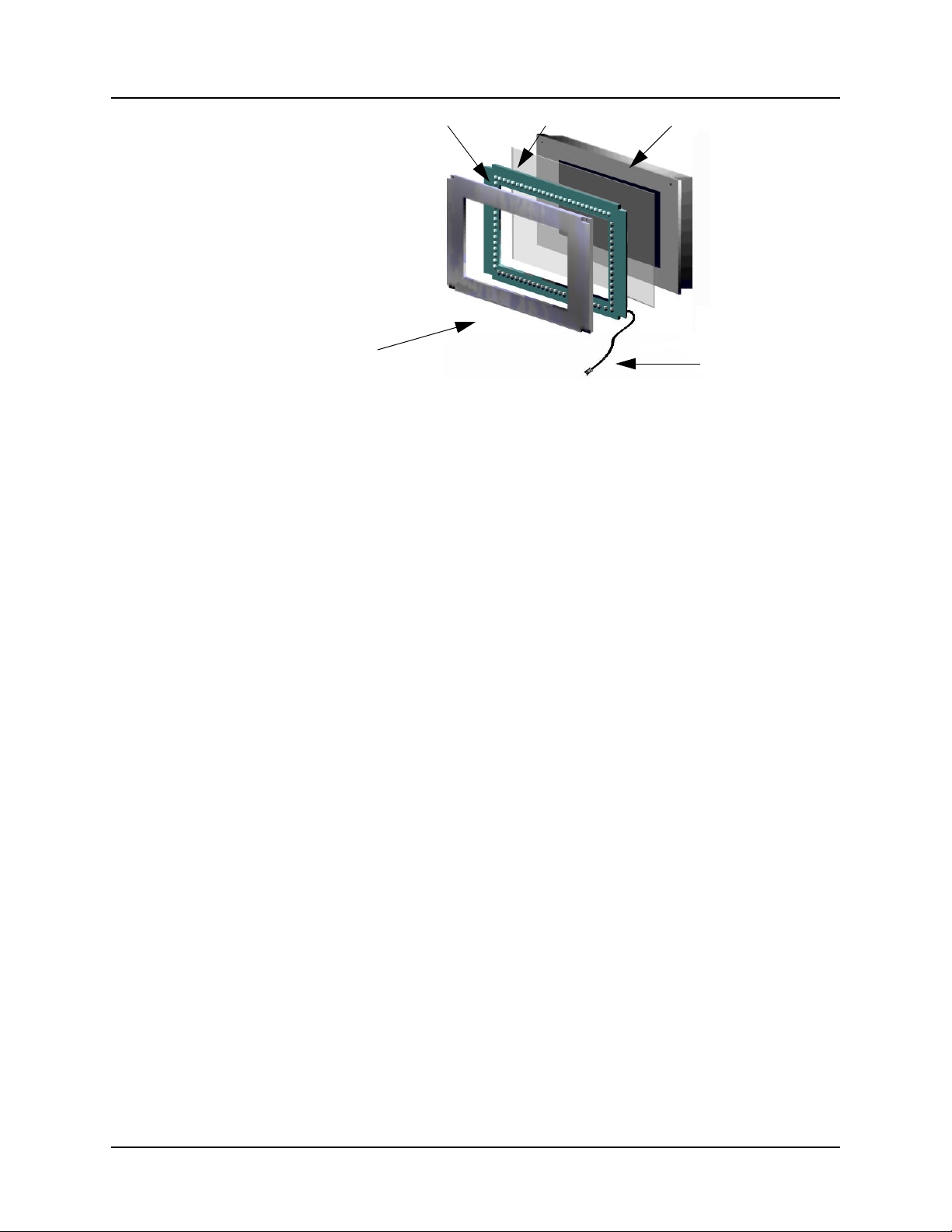
As shown in Figure 1-2, a Carroll Touch modular touch frame designed
to function with a flat panel is composed of an opto-matrix frame, an
IR-transparent protective bezel, and a transparent filter. To complete
the touch system, the modular touch frame is linked to a modular touch
controller via the modular digital interface (MDI), which is a standard
8-pin telephone-type plug attached to the touch frame by an 8-pin cable.
1-2 Modular Flat Panel Mounting and Environments Guide
Page 10
CARROLL TOUCH Chapter 1 - Introduction
Flat Panel DisplayFilterOpto-Matrix Frame
Bezel 8-Pin Telephone-
Type Cable
Figure 1-2. Modular Flat Panel Touch System Components
Environmental Factors
Traditionally, the successful implementation of a scanning IR touch
system has required that certain factors in the operational environment
be addressed. Historically, the environmental factors that could
influence the operation of a touch system were temperature, shock and
vibration, chemicals, moisture, ambient light, and particulate
contaminants (dust, dirt, etc.). Today’s Carroll Touch modular touch
systems with their improved hardware, software and firmware,
compensate for these environmental conditions, along with such factors
as misalignment or degradation of the opto-electronic devices, reducing
their ability to affect touch system operations.
Temperature
Carroll Touch’s use of solid state electronics and its ASIC-based
modular circuitry enables the touch system to withstand and adapt to
temperature extremes as well or better than the host display and system.
The standard Carroll Touch modular flat panel system is designed to
function in the temperature range from 0° C to 50° C (32° F to 122° F)
and can be stored in the range from -20° C to 75° C (-4° F to 167° F).
Customer systems have been designed to function at temperatures from
-55° C to 125° C (-67° F to 257° F). For heat dissipation, Carroll Touch
modular touch systems are designed to operate at altitudes up to 10,000
feet (3,048 meters) and at 0% to 95% non-condensing humidity, over
the full temperature range.
Modular Flat Panel Mounting and Environments Guide 1-3
Page 11

Chapter 1 - Introduction CARROLL TOUCH
Shock and Vibration
Carroll Touch modular flat panel touch systems can more than
withstand shock and vibration conditions that will disable a typical flat
panel display. The lightweight solid state circuit card assemblies,
because of their low mass, are relatively immune to shock and
vibration, as are the other components of the system.
In the unlikely event that a beam is lost to severe local shock, fault
tolerance begins and the touch system continues to function by virtue
of its failed beam algorithms while reporting the beam loss.
Chemicals
The modular touch system relies on the basic properties of the materials
from which it is manufactured for environmental protection. The
polycarbonate resins from which the touch system components are
manufactured and their resistance to harsh chemicals and
environmental extremes are discussed in Chapter 3.
If chemical factors make your operating environment unsuitable for
some components of the touch system, other materials and coatings for
touch systems and their components are available. These materials and
coatings, along with tips on sealing the touch system, are discussed in
Chapter 4.
Moisture
Carroll Touch modular flat panel touch system are designed to function
at up to 95% non-condensing humidity. In addition, modular flat panel
systems can be sealed, making the touch system impervious to
precipitated moisture, such as rain, dousing, or sprinkling, as long as it
is mounted in a vertical position. As shown in Figure 1-3, an improperly
mounted system can permit water to pool in the face of the modular
system, absorbing a portion of the IR beam strength. The
programmable gain features built into the ASIC and firmware will
compensate for losses of beam strength in the range of 50-90% with no
system failure.
1-4 Modular Flat Panel Mounting and Environments Guide
Page 12

CARROLL TOUCH Chapter 1 - Introduction
Figure 1-3. Mounting to Prevent Moisture Accumulation
Ambient Light
Since IR touch systems operate using the IR portion of light, ambient
light, the light in the touch environment, has long been a source of
concern. Ambient light has varying levels of IR radiation, depending on
whether the source of visible light is IR rich, as is sunlight, or IR poor,
as is fluorescent light commonly used in offices. A high ambient light
level in the well lit office would have little effect on the functionality of
a scanning IR touch system.
Carroll Touch has developed advanced design techniques that allow the
modular flat panel touch system to adjust to high levels of ambient
light. These methods involve hardware design and the use of patented
signal processing circuitry and algorithms, which can handle very high
ambient light levels. Carroll Touch modular flat panel touch systems
can tolerate well over 7,500 footcandles, and operate in full sunlight
with only minor modification. Typical ambient light measurements are
given in Table 1-1.
Table 1-1. Environmental Light Strengths
Ambient Light Footcandles Ambient Light Footcandles
Direct sunlight 10,000 Twilight 1
Indirect sunlight 4,000 Well lit office 80
Overcast day 100 Well lit factory 70
Dark overcast day 10
Modular Flat Panel Mounting and Environments Guide 1-5
Page 13

Chapter 1 - Introduction CARROLL TOUCH
Particulates
Particulate contaminants such as dust, powder, smoke, and other
particles found in the atmosphere of offices, manufacturing facilities,
industrial and outdoor sites, have been considered the most common
environmental hazard to IR touch systems. The two traditional places
for such buildup were on the outer surface of the protective bezel, and
on the IR LEDs and phototransistors themselves. The buildup of
particulates around the LEDs and receivers is easily prevented by basic
sealing. Today’s modular systems are so easily sealed that such buildup
is preventable at little cost. Guidelines for sealing a modular flat panel
touch system can be found in Chapter 4 of this guide.
While particulate buildup on the protective bezel can lower signal
strength in the opto-matrix grid, the integrity of the touch system is
safeguarded by programmable gain and servo-loop circuitry. This
circuitry and the attendant firmware dynamically compensates for
degradation of the opto-electronic devices and for the effects of such
environmental factors as ambient light variation and the accumulation
of particulate contaminants.
Despite this built-in protection against weakened signal strength caused
by buildup of particulates, the outer surface of the protective bezel
should be dusted and/or cleaned with a mild soapy solution as needed.
Application Environments
Table 1-2 identifies four types of application environments, gives
examples of each, and lists the environmental factors common to each.
Table 1-2. Application Environments
Application
Environment
Indoor Offices, lobbies, schools, retail Particulate contaminants
Outdoor Outdoor information kiosks,
Industrial Manufacturing facilities, laboratories,
Typical Locations Environmental Factors
Particulate contaminants, moisture,
automated teller machines (ATMs)
normal shop floor environments
chemicals, ambient light,
temperature, shock
Particulate contaminants, moisture,
chemicals
Harsh Ruggedized industrial equipment,
aircraft, vehicles, severe shop floor
environments
1-6 Modular Flat Panel Mounting and Environments Guide
Particulate contaminants, moisture,
chemicals, ambient light,
temperature, shock and vibration
Page 14
2
T
Mounting
Mounting Techniques
Techniques
his chapter describes and illustrates four separate mounting
schemes, each of which is designed to increase the functionality of
the touch system in a different environment. The mounting methods
include:
• Simplest Mounting Method.
• Typical NEMA 4 Mounting Method.
• Anti-Shock/Vibration Mounting Method.
• Industrial or Medical Mounting Method.
Modular Flat Panel Mounting and Environments Guide 2-1
Page 15

Chapter 2 - Mounting Techniques CARROLL TOUCH
Simplest Mounting Method
The simplest mounting technique provides effective sealing by merely
using industrial strength double-sided tape to adhere both the touch
system and the host display to the inside of a kiosk or enclosure
opening. Front and side views are shown in Figures 2-1 and 2-2.
Back Housing
Flat Panel Display
Filter
Gasket
Bezel
Double-Sided Tape
8-Pin TelephoneType Cable
Figure 2-1. Simplest Mounting Method (Front View)
2-2 Modular Flat Panel Mounting and Environments Guide
Page 16

CARROLL TOUCH Chapter 2 - Mounting Techniques
Bezel
Flat Panel Display
Back
Housing
Viewing
Area
Filter
Gasket
Front Panel
Contact Point of
Double-Sided Tape
Figure 2-2. Simplest Mounting Method (Side View)
Modular Flat Panel Mounting and Environments Guide 2-3
Page 17

Chapter 2 - Mounting Techniques CARROLL TOUCH
Typical NEMA 4 Mounting Method
Figures 2-3 and 2-4 show the front and side views of a typical NEMA
4 sealable mounting. For more information on gasketing materials, see
Chapter 4 of this guide.
Back Housing
Flat Panel Display
Filter
Gasket
Bezel
Front Panel Gasket
8-Pin TelephoneType Cable
Figure 2-3. Typical NEMA 4 Mounting Method (Front View)
2-4 Modular Flat Panel Mounting and Environments Guide
Page 18

CARROLL TOUCH Chapter 2 - Mounting Techniques
Bezel
Flat Panel Display
Back Housing
Viewing
Area
Filter
Front Panel
Gasket
Front Panel Gasket
Figure 2-4. Typical NEMA 4 Mounting Method (Side View)
Modular Flat Panel Mounting and Environments Guide 2-5
Page 19

Chapter 2 - Mounting Techniques CARROLL TOUCH
Anti-Shock/Vibration Mounting Method
The shock and vibration resistance of a Carroll Touch modular touch
system can be further enhanced by mounting techniques such as the one
shown in Figure 2-5. This mounting is used in commercial aircraft and
must withstand the vibration of the aircraft engines and the shock of air
turbulence and landings, which can often be measured in impacts of
multiple Gs of force.
Shock Absorbers
Back Housing
Flat Panel Display
Filter
Gasket
Touch Frame
Panel Gasket
Front Housing
Figure 2-5. Anti-Shock/Vibration Mounting Method
2-6 Modular Flat Panel Mounting and Environments Guide
Page 20

CARROLL TOUCH Chapter 2 - Mounting Techniques
Industrial or Medical Mounting Method
The sealing of a touch system is nowhere more important than in the
surgical operating room (O.R.), where the entire system must be
scrubbed between uses. The capacity to seal a system can be enhanced
by the mounting techniques shown in Figure 2-6. The use of a Carroll
Touch modular touch system and compact flat panel display in cramped
conditions such as those found in the surgical O.R. is further supported
by the touch frame’s capacity for being located up to six feet from its
host computer, connected only by a standard 8-pin telephone-type jack
and cable.
Back Housing
Flat Panel Display
Filter
Gasket
Touch Frame
Panel Gasket
Front Housing
Figure 2-6. Industrial or Medical Mounting Method
Modular Flat Panel Mounting and Environments Guide 2-7
Page 21

Chapter 2 - Mounting Techniques CARROLL TOUCH
2-8 Modular Flat Panel Mounting and Environments Guide
Page 22

3
T
Bezel/Filter
Bezel/Filter Assembly
Assembly
his chapter describes the component materials and chemical
properties of the bezel/filter assembly. Topics discussed include:
• Component Materials.
• Polycarbonate Chemical Resistance.
Modular Flat Panel Mounting and Environments Guide 3-1
Page 23

Chapter 3 - Bezel/Filter Assembly CARROLL TOUCH
Component Materials
The IR-transparent protective bezel used by Carroll Touch’s standard
modular flat panel touch systems, shown in Figure 1-2, is vacuum
formed from polycarbonate resin. This same resin in transparent grades
is used to form the standard touch system filter.
From a wide spectrum of possible manufacturing materials,
polycarbonate was chosen because it is rugged, IR-transparent and
thermoformable. Indeed, this material is so impact resistant that it is
used for bulletproof glass. Polycarbonates maintain their physical
strength far past 100° C, even under impact testing.
Modular touch system filters with special optical properties such as
polarization, anti-glare and anti-reflection are available from Carroll
Touch. Polarizing filters are more sensitive to temperature extremes
than polycarbonate filters. Contact Carroll Touch for options and
details.
Polycarbonate Chemical Resistance
Certain combinations of chemical environments, temperature, and
stress can adversely affect thermoplastic parts made from
polycarbonate resin. For this reason, lubricants, gaskets, O-rings,
cleaning solvents, or any other material that may come in contact with
the finished part should be carefully evaluated under end-use
conditions for compatibility.
Polycarbonate resin is generally stable to water, mineral acids and
organic acids.
Testing of the polycarbonate resins used in the manufacture of Carroll
Touch touch system components has yielded the results shown in Table
3-1. However, interpretation of the test results is somewhat subjective.
If a material is found to be incompatible in a short term test, it will
usually be incompatible in the field. The converse, however, is not
always true. Favorable performance is no guarantee that actual end-use
conditions have been duplicated.
Caution
The results of these tests should be used as a guide only. We
recommend that you test production parts under true end-use
conditions.
3-2 Modular Flat Panel Mounting and Environments Guide
Page 24

CARROLL TOUCH Chapter 3 - Bezel/Filter Assembly
Table 3-1. Effects of Chemical Classes on Polycarbonates
Chemical Class Effects
Acids No effect under most common conditions of concentration and temperature.
Alcohols Generally compatible at low concentration and room temperature. Higher concentrations
and elevated temperatures results in etching and attack, evidenced by decomposition.
Alkalis Generally compatible at low concentration and room temperature. Higher concentrations
Aliphatic Hydrocarbons Generally compatible.
Amines Surface crystallization and chemical attack. Avoid.
Aromatic Hydrocarbons Partial solvents and severe stress cracking agents (i.e., xylene, toluene). Avoid.
Detergents and Cleaners Mild soap solutions are compatible. Avoid strong alkaline materials.
Esters Cause severe crystallization. Partial solvents. Avoid.
Halogenated Hydrocarbons Solvents. Avoid.
Ketones Cause severe crystallization and stress cracking. Partial solvents. Avoid.
Silicone Oils and Greases Generally compatible up to 185° F. Avoid those that contain aromatic hydrocarbons.
and elevated temperatures results in etching and attack, evidenced by decomposition
Polycarbonate is dissolved by the following substances:
Chloroform Dioxane Methylene chloride Pyridine
Cresol Ethylene dichloride
Polycarbonate may not be resistant to the following substances:
Acetaldehyde Butyric acid Ethane tetrachloride Phosphorous trichloride
Acetic acid (concentrated) Carbolic acid Ethylamine Propionic acid
Acetone Carbon disulphide Ethyl ether Sodium sulfide
Acrylonitrile Carbon tetrachloride Ethylene chlorohydrin Stryrene
Ammonium fluoride Caustic potash sol (5%) Formic acid (concentrated) Sulfuryle chloride
Ammonium sulfide Caustic soda sol. (5%) Freon (refrigerant and propellant) Tetrahydronapthalene
Benzene Chlorobenzene Nitrobenzene Thiophene
Benzoic acid Cyclohexanone Nitrocellulose lacquer Toluene
Benzyl alcohol Cyclohexane Phenol Xylene
Bromobenzene Dimethyl formamide Phosphorous hydroxy chloride
Polycarbonate has limited resistance to the following substances:
Cyclohexanol Hydrochloric acid (concentrated) Nitric acid (concentrated) Sulphuric acid (concentrated)
Gasoline Milk of lime (CaOH)
Modular Flat Panel Mounting and Environments Guide 3-3
Page 25

Chapter 3 - Bezel/Filter Assembly CARROLL TOUCH
At room temperature, polycarbonate is resistant to the following
substances:
Acetic acid (20%) Cyclohexane Milk Salt solution (10%)
Aluminum chloride Decahydronapthalene Mineral heating oil Silicone oil
Aluminum sulphate Diesel oil Mineral water Silver nitrate
Ammonium chloride Ethyl alcohol (96%) Mustard Soap (soft & hard)
Ammonium nitrate Fish oil Nickel sulphate Sodium bicarbonate
Ammonium sulphate Floor polish Nitric acid (10% & 20%) Sodium bisulphate
Antimony trichloride Formic acid (10%) Oleic acid Sodium bisulphite
Arsenic acid (20%) Formalin (30%) Orange juice, peel Sodium carbonate
Axle oil Gasoline (low aromatic) Oxalic acid Sodium chlorate
Beer Glazier’s putty Paraffin oil Sodium chloride
Borax Glycerine Pentane Sodium hypochlorite
Brake fluid Glycol Petrol Sodium sulphate
Butyl alcohol Grapefruit peel, juice Petroleum ether Spindle oil
Calcium chloride Gypsum Phosphoric acid, concentrated Stannous chloride
Calcium nitrate Hydrochloric acid (10% & 20%) Potassium aluminum alum Sulphur
Castor oil Hydrogen peroxide (30%) Potassium bichromate Sulphuric acid (10% & 20%)
Cement Hydrofluoric acid (20%) Potassium bromate Tartaric acid (30%)
Chlorinated lime paste Ink Potassium bromide Tincture of iodine
Chlorinated lime sol. (2%) Iron chloride Potassium chloride Tomato juice, concentrate
Chrome alum Iron sulphate Potassium nitrate Transformer oil
Chromic acid (20%) Insulating tape Potassium perchlorade Trichloroacetic acid
Citric acid (40%) Isoamyl alcohol Potassium permanganate Turpentine
Cocoa Lactic acid Potassium persulphate Vacuum pump oil
Coffee Linseed oil & varnish Potassium sulphate Vinegar
Cognac Liqueur Propyl alcohol Vodka
Compressor oil Magnesium chloride Rapeseed oil Water
Copper chloride Magnesium sulphate Refined oil Wine
Copper sulphate Manganese sulphate Rum Zinc chloride
Cuprous chloride Mercuric chloride Salad oil Zinc sulphate
3-4 Modular Flat Panel Mounting and Environments Guide
Page 26

4
O
Sealing and
Sealing and Coating
Coating
nce an application environment is analyzed, most customers find
that they will be able to use Carroll Touch modular flat panel
touch systems without any adaptation. However, in some instances, it
may be necessary to enhance the standard touch system with additional
sealing or conformal coating.
This chapter discusses the following topics:
• Sealing.
• Coating.
Modular Flat Panel Mounting and Environments Guide 4-1
Page 27

Chapter 4 - Sealing and Coating CARROLL TOUCH
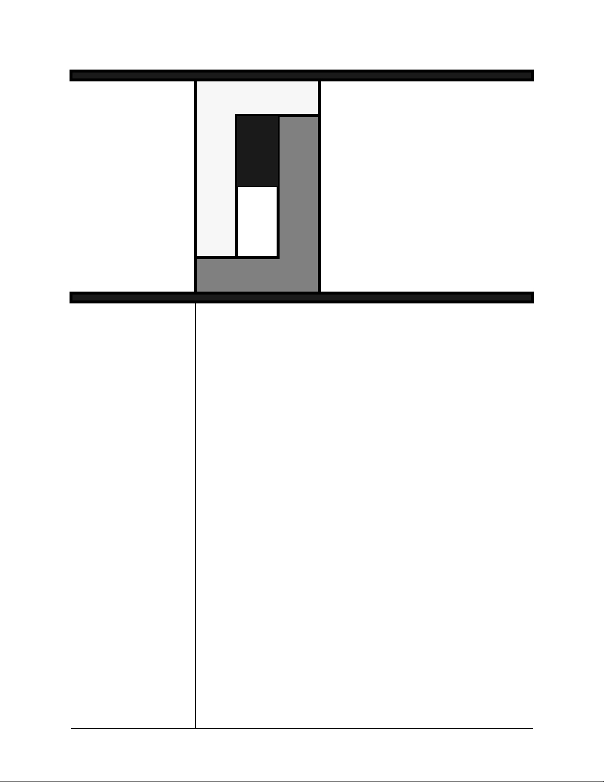
Sealing
As shown in Figure 4-1, the modular flat panel touch system is sealed
by the application of gasketing material or sealant between the two
contact edges of the IR-transparent protective bezel and the filter. This
seal provides adequate protection against accidental exposure to
liquids, such as that involved in cleaning or spillage.
Figure 4-1. Modular Flat Panel Touch System Sealing
Modular bezels are fitted with gasket material at the factory. Carroll
Touch offers enhanced sealing with assorted sealants and gasket
materials as a custom service.
With CRT touch systems, gasketing is the preferred method, since it
allows easy disassembly and efficient access for cleaning and
maintenance of the touch system. The amount of cleaning required is
dependent on the amount of dust or moisture in the environment and the
quality of the seal. Unlike CRT monitors, flat panels do not attract dust.
Therefore, the buildup of dust in the interior of a modular flat panel
touch system does not occur.
Gasket material characteristics that must be considered are
compression resilience (how the material bounces back after
compression), and moisture and chemical resistance. Recommended
gasket materials are polyester, urethane, and silicone.
Polyester and urethane are available as open cell or closed cell
materials. Open cell polyester and urethane cost less than silicone.
Closed cell sealing material is preferred in environments containing
moisture or chemicals. Polyester and urethane are resistant to ozone,
oxidation and hydrocarbons and can withstand wide temperature
variations.
4-2 Modular Flat Panel Mounting and Environments Guide
Page 28

CARROLL TOUCH Chapter 4 - Sealing and Coating
Silicone is an environmentally inert material available in sponge or
solid form. It is recommended for application environments that
involve electrostatic discharge, severely caustic or actively corrosive
chemicals, high moisture, broad temperature ranges, oxidation, or
acids.
Coating
In the case of certain high density or high current circuits, or in harsh or
explosive environments where the intent is to prevent corrosion,
erosion, arcing or sparking, or in the face of critical service issues
where the failure of a circuit could cause loss of human life, conformal
coating is used as a second method to seal a circuit. Carroll Touch has
used conformal coating only rarely in the past for extremely ruggedized
or military applications.
Conformal coating is a polyurethane resin insulating compound that is
sprayed on or washed over the printed circuit board assembly during
the manufacturing process. It may be required in outdoor information
systems, shipboard applications, industrial environments, or wherever
moisture or corrosives must be prevented from entering the system.
Conformal coating is the ultimate seal for the touch system, providing
an excellent environmental shield from fungus, thermal shock,
moisture and chemicals such as sulphuric acid.
Modular Flat Panel Mounting and Environments Guide 4-3
Page 29

Chapter 4 - Sealing and Coating CARROLL TOUCH
4-4 Modular Flat Panel Mounting and Environments Guide
Page 30

CARROLL TOUCH Glossary
Glossary
ambient light The level of light to be found in the physical environment of a
given touch application, normally measured in lux or footcandles.
axis (x-axis, y-axis) The two dimensions that make up the touch coordinate system.
The x-axis (horizontal) is composed of the vertical physical
beams or opto-pairs (the physical x-axis). The y-axis (vertical) is
composed of the horizontal physical beams or opto-pairs (the
physical y-axis).
beam The infrared light transmitted by an IR LED and received by a
phototransistor, which are set opposite each other in the touch
frame.
bezel The IR-transparent plastic protective housing of the modular flat
panel touch frame, which is fastened to the filter.
broken beam A beam in which the infrared light level received by the
IR-sensitive phototransistor falls below a threshold value set by
the touch system firmware. In normal operation, this is due to the
user’s finger obstructing the beam path from the LED to the
phototransistor. However, broken beams may also result from a
defective LED, phototransistor, or other touch system hardware,
and from other obstructions of the beam path. See also beam.
host (host system) The computer system to which the IR touch system is added.
MDI See modular digital interface (MDI).
modular digital interface
(MDI)
opto-matrix frame A rectangle, each side of which is comprised of a circuit board.
opto-pair The LED/phototransistor combination that transmits and receives
touch controller The circuitry and firmware necessary to interpret touch data for a
The frame-to-controller interface created by confining all analog
functions to the frame. The MDI makes a standard touch frame
controller-independent and reduces the touch system cabling
requirement to a simple 8-pin standard phone cable up to six feet
long.
Two adjacent circuit boards contain banks of IR LEDs, while the
second two contain banks of complementary phototransistor
receivers. The horizontal boards contain the banks of opto-pairs
that make up the x-axis of the touch screen. The vertical boards
contain the banks of opto-pairs that make up the y-axis of the
touch screen.
an IR beam. See beam.
host computer.
Modular Flat Panel Mounting and Environments Guide GL-1
Page 31

Glossary CARROLL TOUCH
touch frame The portion of the modular touch system that consists of the
opto-matrix frame, the IR-transparent protective bezel and the
modular digital interface (MDI).
touch system The collection of all the components that are necessary to detect a
touch and report it to the host. This collection usually consists of
the touch frame or screen, protective bezel, and touch frame
controller.
GL-2 Modular Flat Panel Mounting and Environments Guide
Page 32

CARROLL TOUCH Index
Index
A
altitudes . . . . . . . . . . . . . . . . . . . . . . . . . . . . . . . . . . . . . . . . . . . . . 1-3
ambient light . . . . . . . . . . . . . . . . . . . . . . . . . . . . . . . . . . 1-3, 1-5, 1-6
anti-glare filters . . . . . . . . . . . . . . . . . . . . . . . . . . . . . . . . . . . . . . . 3-2
anti-reflection filters . . . . . . . . . . . . . . . . . . . . . . . . . . . . . . . . . . . 3-2
anti-shock/vibration mounting technique . . . . . . . . . . . . . . . . . . . 2-6
application environments . . . . . . . . . . . . . . . . . . . . . . . . . . . . . . . 1-6
arcing . . . . . . . . . . . . . . . . . . . . . . . . . . . . . . . . . . . . . . . . . . . . . . 4-3
B
bezel . . . . . . . . . . . . . . . . . . . . . . . . . . . . . . . . . . . . 1-2, 1-6, 3-2, 4-2
C
chemicals . . . . . . . . . . . . . . . . . . . . . . . . . . . . . . . . 1-3, 1-4, 4-2, 4-3
commercial aircraft, mounting techniques in . . . . . . . . . . . . . . . . 2-6
conformal coating . . . . . . . . . . . . . . . . . . . . . . . . . . . . . . . . . . . . . 4-3
corrosion . . . . . . . . . . . . . . . . . . . . . . . . . . . . . . . . . . . . . . . . . . . . 4-3
D
dust . . . . . . . . . . . . . . . . . . . . . . . . . . . . . . . . . . . . . . . . . . . . .1-6, 4-2
E
effects of chemicals on polycarbonate resin . . . . . . . . . . . . . . . . . 3-2
electrostatic discharge . . . . . . . . . . . . . . . . . . . . . . . . . . . . . . . . . . 4-3
environmental factors . . . . . . . . . . . . . . . . . . . . . . . . . . . . . . . . . . 1-3
erosion . . . . . . . . . . . . . . . . . . . . . . . . . . . . . . . . . . . . . . . . . . . . . 4-3
F
filter . . . . . . . . . . . . . . . . . . . . . . . . . . . . . . . . . . . . . . . .1-2, 3-2, 4-2
fluorescent light . . . . . . . . . . . . . . . . . . . . . . . . . . . . . . . . . . . . . . 1-5
G
gasket materials . . . . . . . . . . . . . . . . . . . . . . . . . . . . . . . . . . .4-2, 4-3
gasket properties . . . . . . . . . . . . . . . . . . . . . . . . . . . . . . . . . . . . . . 4-2
Modular Flat Panel Mounting and Environments Guide IN-1
Page 33

Index CARROLL TOUCH
H
heat dissipation . . . . . . . . . . . . . . . . . . . . . . . . . . . . . . . . . . . . . . . 1-3
humidity . . . . . . . . . . . . . . . . . . . . . . . . . . . . . . . . . . . . . . . . .1-3, 1-4
I
industrial or medical mounting technique . . . . . . . . . . . . . . . . . . 2-7
infrared radiation . . . . . . . . . . . . . . . . . . . . . . . . . . . . . . . . . .1-2, 1-5
L
light emitting diodes (LEDs) . . . . . . . . . . . . . . . . . . . . . . . . .1-2, 1-6
M
modular digital interface (MDI) . . . . . . . . . . . . . . . . . . . . . . . . . . 1-2
moisture . . . . . . . . . . . . . . . . . . . . . . . . . . . . . . . . . 1-3, 1-4, 4-2, 4-3
mounting technique
anti-shock/vibration . . . . . . . . . . . . . . . . . . . . . . . . . . . . . . . . 2-6
industrial or medical . . . . . . . . . . . . . . . . . . . . . . . . . . . . . . . . 2-7
NEMA 4 . . . . . . . . . . . . . . . . . . . . . . . . . . . . . . . . . . . . . . . . . 2-4
simple . . . . . . . . . . . . . . . . . . . . . . . . . . . . . . . . . . . . . . . . . . . 2-2
N
NEMA 4 mounting technique . . . . . . . . . . . . . . . . . . . . . . . . . . . . 2-4
O
opto-matrix frame . . . . . . . . . . . . . . . . . . . . . . . . . . . . . . . . . . . . . 1-2
opto-pairs . . . . . . . . . . . . . . . . . . . . . . . . . . . . . . . . . . . . . . . . . . . 1-2
oxidation . . . . . . . . . . . . . . . . . . . . . . . . . . . . . . . . . . . . . . . . .4-2, 4-3
ozone . . . . . . . . . . . . . . . . . . . . . . . . . . . . . . . . . . . . . . . . . . . . . . . 4-2
P
particulate contaminants . . . . . . . . . . . . . . . . . . . . . . . . . . . . .1-3, 1-6
phototransistors . . . . . . . . . . . . . . . . . . . . . . . . . . . . . . . . . . . .1-2, 1-6
physical beams . . . . . . . . . . . . . . . . . . . . . . . . . . . . . . . . . . . . . . . 1-2
polarizing filter . . . . . . . . . . . . . . . . . . . . . . . . . . . . . . . . . . . . . . . 3-2
polycarbonate resins . . . . . . . . . . . . . . . . . . . . . . . . . . . . . . . .1-4, 3-2
polycarbonate resins, resistance to various substances . . . . . .3-2, 3-3
polycarbonate resins, testing . . . . . . . . . . . . . . . . . . . . . . . . . . . . . 3-2
IN-2 Modular Flat Panel Mounting and Environments Guide
Page 34

CARROLL TOUCH Index
polyester gasket . . . . . . . . . . . . . . . . . . . . . . . . . . . . . . . . . . . . . . 4-2
polyurethane resin . . . . . . . . . . . . . . . . . . . . . . . . . . . . . . . . . . . . . 4-3
powder . . . . . . . . . . . . . . . . . . . . . . . . . . . . . . . . . . . . . . . . . . . . . 1-6
S
sealing . . . . . . . . . . . . . . . . . . . . . . . . . . . . . . . . . . . 1-6, 2-2, 2-7, 4-2
shock . . . . . . . . . . . . . . . . . . . . . . . . . . . . . . . . . . . . . . . . 1-3, 1-4, 2-6
silicone gasket . . . . . . . . . . . . . . . . . . . . . . . . . . . . . . . . . . . . . . . . 4-3
simple mounting technique . . . . . . . . . . . . . . . . . . . . . . . . . . . . . . 2-2
smoke . . . . . . . . . . . . . . . . . . . . . . . . . . . . . . . . . . . . . . . . . . . . . . 1-6
sparking . . . . . . . . . . . . . . . . . . . . . . . . . . . . . . . . . . . . . . . . . . . . 4-3
sunlight . . . . . . . . . . . . . . . . . . . . . . . . . . . . . . . . . . . . . . . . . . . . . 1-5
surgical operating room, mounting techniques in . . . . . . . . . . . . 2-7
T
temperature . . . . . . . . . . . . . . . . . . . . . . . . . . . . . . . . . . . . . . . . . . 1-3
touch systems . . . . . . . . . . . . . . . . . . . . . . . . . . . . . . . . . . . . . . . . 1-2
U
urethane gasket . . . . . . . . . . . . . . . . . . . . . . . . . . . . . . . . . . . . . . . 4-2
V
vibration . . . . . . . . . . . . . . . . . . . . . . . . . . . . . . . . . . . . .1-3, 1-4, 2-6
Modular Flat Panel Mounting and Environments Guide IN-3
Page 35

Index CARROLL TOUCH
IN-4 Modular Flat Panel Mounting and Environments Guide
Page 36

CONTACTING CARROLL TOUCH:
Carroll Touch (512) 244-3500Switchboard
2800 Oakmont Drive (800) 386-8241Toll Free
Round Rock, Texas 78664 (512) 388-5643Order Assistance
(512) 388-5509Technical Support
(512) 244-7040Fax
http://www.carrolltouch.com (512) 388-5668Bulletin Board (14400K,N81)
 Loading...