

Page 1
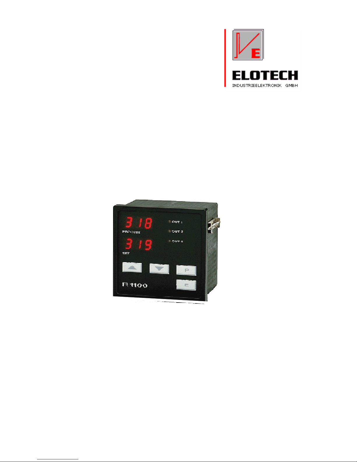
R 1100
The Temperature Controller
Heat-only Controller
Heating-off-Cooling Controller
DIN-Format: 96 x 96 mm
Installation depth: 67 mm
Microprocessor-based Temperature Controller
Description And Operating Manual
R1100-EN 09/2010
Page 2
2
I. Contents
I. Contents ......................................................................................................................................................2
II. Type Code...................................................................................................................................................2
III. Connection Diagram ................................................................................................................................3
IV. Installation Instructions ............................................................................................................................3
V. Display and Keyboard..................................................................................................................................4
VI. Operating Levels......................................................................................................................................5
VII. Configuration Level ..................................................................................................................................6
VIII. Parameter Level ......................................................................................................................................9
IX. O P E R A T I N G L E V E L .............................................................................................................12
X. Technical Data ..........................................................................................................................................13
XI. Error displays.........................................................................................................................................13
Please read this operating manual before starting up carefully.
Observe the installation and connecting instructions.
Before operation, the unit must be configurated for its intended purpose under an expert guidance.
(e.g. controller type, sensor type and range, alarm adjustment etc.)
See: „Configuration Level“ and „Parameter Level“
Attention: The „heating“- or „cooling“-outputs can be active while programming or configuring the controller.
This can cause a damage either to the plant itself or its contents.
Disclaimer of liability
We have checked the contents of the document for conformity with the hardware and software described. Nevertheless, we are unable
to preclude the possibility of deviations so that we are unable to assume warranty for full compliance. The information given in the
publication is, however, reviewed regularly. Necessary amendments are incorporated in the following editions.
We would be pleased to receive any improvement proposals which you may have.
The information contained herein is subject to change without notice.
II. Type Code
R 1100 - x - 00 - z
z: 1 Power supply: 230 V AC
z: 2 Power supply: 115V AC
z: 3 Power supply: 24V AC
z: 5 Power supply: 24V DC (+/-25%)
x: 10 Control output OUT1: Relay, control output „heating“ or „cooling“
Output OUT2: Relay, control output „cooling“ or „alarm 2“ output
Output OUT3: Relay, „alarm 3“ output
x: 20 Control output OUT1: Bist. Voltage, control output „heating“ or „cooling“
Output OUT2: Relay, control output „cooling“ or „alarm 2“ output
Output OUT3: Relay, „alarm 3“ output
Page 3
3
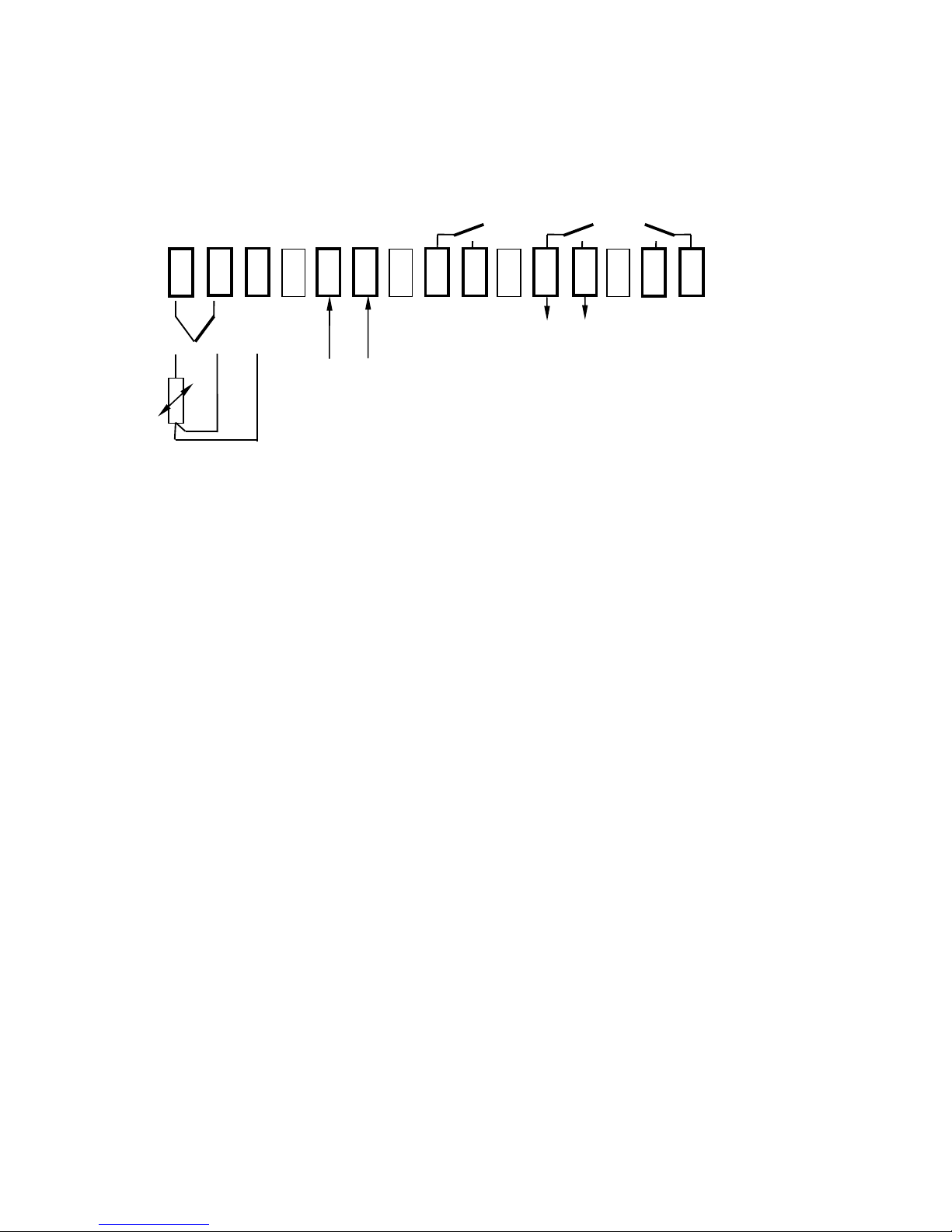
III. Connection Diagram
OUT 2 OUT 1 OUT 3
cooling or heating or
alarm 2 cooling alarm 3
relay relay relay
1 2 3 4 5 6 7 8 9 10 11
+ TC - +
bist.
N L voltage output
power supply types R 1100-20
- +
DC
Pt 100 / RTD
It is not permitted to connect the grounds of the sensor- and bist. voltage-outputs with each other.
Control output OUT 1:
2-point-controller: "Heating" e.g „Cooling“
3-point-controller (heating-off-cooling): „Heating“
Control- or alarm output OUT 2:
2-point-controller: "Alarm 2“
3-point-controller: „Cooling“
Alarm Output OUT 3: „Alarm 3“
IV. Installation Instructions
Make certain that the devices described here are used only for the intended purpose.
They are intended for installation in control panels. The controller must be installed so that it is
protected against impermissible humidity and severe contamination.
In addition, make sure that the permitted ambient temperature is not exceeded.
The electrical connections must be made according to the relevant locally applicable regulations.
If using a thermocouple sensor, the compensation cables must be laid directly to the controller
terminals.
Transducers must be connected only in compliance with the programmed range.
Transducer cables and signal lines (e.g. logic or linear voltage outputs) must be laid physically
separated from control lines and mains voltage supply cables (power cables) and must be shielded.
Spatial separation between controller and inductive loads is recommneded.
Interference from contactor coils must be suppressed by connecting adapted RC-combinations
parallel to the coils. Control circuits (e.g. for contactors) should not be connected to the mains power
supply terminals of the controller.
IMPORTANT:
Before operation, the unit must be configurated for its intended purpose
(e.g. controller type, sensor type and range, alarm adjustment etc.).
Please see „Configuration Level“.
Page 4
4
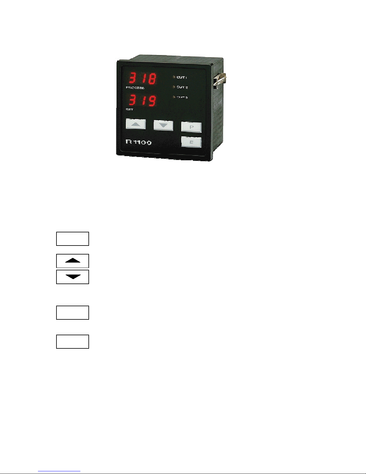
V. Display and Keyboard
Display PROCESS : Process Value
Display SET : Setpoint Value
LED OUT 1: Output OUT1 active: Control Output
LED OUT 2: Output OUT2 active: Control Output or Alarm Output A2
LED OUT 3: Output OUT3 active: Alarm Output A3
P
Parameter key
Adjustment of chosen parameter (e.g. setpoint) to higher or lower values.
Short operation: single-step adjustment
Longer operation: quick-scanning
When the parameter adjustments have been altered but not with key „E“ entered,
the display will flash bright/dark.
E
Confirmation and storage of the pre-selected values
The display will shortly be switched dark as a control of this function.
P
Sets the parameter back to the originally stored value.
Any altrations made to the parameters, that are not confirmed (E-key) within
30 seconds, will not be accepted and the parameter will return to ist originally
stored value.
Page 5

5
P
P
VI. Operating Levels
The operation of the controller is divided into three levels.
Two seconds after switching on the unit, the controller will automatically be in the operating level.
press press
and and
appr. 5 sec.
power Operating- Parameter- Configuration-
on: level level level
process value Y (output ratio) C.Co
setpoint value
1 LY SEn
AL3
AL2 OFS EL .x
Back into the operating level:
- Press 1 sec.
- or automatically after 30 sec.
Operating level
Process- and Setpoint value will be displayed simultaneously.
Within the operating level the setpoint and the alarm value can be adjusted
by pressing the " " / " " - keys.
Every adjustment has to be quit by pressing the „ E “ - key.
All parameters within the operating level can , in succession, be displayed by pressing the „ P “ - key
and adjusted by pressing the " " / " " - keys.
Parameter level
Within the parameter level the values are adjusted to suit each individual process.
This level is reached by simultaneously pressing the "P" - and " E " -keys.
Configuration level
In the configuration level the controller type, input type, sensor range and the alarm behaviour
can be pre-selected.
This primary information has to be entered before taking the controller into operation.
The configuration level is reached by simultaneously pressing the "P" - and " E " - keys
for a period of approx. 5 seconds.
The display of each single parameter within the parameter and configuration levels, and their adjustment,
are made in the same fashion as within the operating level.
After either pressing the „E“ - key for approx. 1 second, or waiting for a period of approx. 30 seconds,
the unit will automatically return to the operating level (display of process value and setpoint).
P
E
E
P
P
P
P
P
P
E
Page 6

6
VII. Configuration Level
Display Parameter Display
"Process" „Set“
C.Co Controller configuration 2 h 2-point-controller „heating“ (ex works)
2 c 2point-controller „cooling“
2nc 2point-controller „cooling“
with non-linear cooling
3 3-point controller "heating - off - cooling"
3nc 3-point controller "heating - off - cooling"
cooling mode with non-linear cooling*)
*) non-linear cooling:
Cooling action can be pre-selected with either linear or
non-linear cooling response curve ( e.g. for vapour cooling).
SEn Sensor selection P1C Pt 100, 0,0...99,9 °C
P1F Pt 100, 32...212 °F
P2C Pt 100, -100...+200°C
P2F Pt 100, -148...+392 °F
P4C Pt 100, 0...400 °C (ex works)
P4F Pt 100, 32...752 °F
P8C Pt 100, 0...800 °C
L4C T/C Fe-CuNi (L), 0...400 °C
L4F T/C Fe-CuNi (L), 32...752 °F
L8C T/C Fe-CuNi (L), 0...800 °C
J8C T/C Fe-CuNi (J), 0...800 °C
n1C T/C NiCr-Ni (K), 0...999 °C
If the Sensor selection is changed, the following parameters will be reset (setting in brackets)
and need to be re-adjusted:
The setpoint (OFF); the alarm value(s) (OFF); the process value offset (OFF);
the lower setpoint limitation (SP.L); the higher setpoint limitation (SP.H).
SP.H higher setpoint limitation
programming range: SP.L ... top range (ex works: 400)
SP.L lower setpoint limitation
programming range: bottom range ... SP.H (ex works: 0)
Page 7

7
Display Parameter Display
"Process" „Set“
C.A3 Alarm 3-Configuration OFF alarm OFF, no alarm signalisation (ex works)
(OUT 3) 1 signal contact: off-on
2 limit contact: off-on
3 limit comparator: off-on-off
4 signal contact: on-off
5 limit contact: on-off
6 limit comparator: on-off-on
7 limit comp. with start-up suppression: off-on-off
The signal contact is adjusted and displayed The limit contact is adjusted and displayed
relative to the setpoint. as an absolute value.
Switching behaviour: Configuration: Switching behaviour: Configuration:
off on
1
off on
2
on off 4 on off
5
setpoint process process
The limit comparator is adjusted and The alarm relay of the limit comparator with
displayed relative to the setpoint. start-up suppression is activated when the
The selected value is effective below and above controller is first switched on. It is only then de the setpoint. activated, when the process value has been
within, and left, the o.k.-zone.
Switching behaviour: Configuration: Switching behaviour: Configuration:
on
off on off
3
off on off
7
on off on
6
setpoint process setpoint process
on: Relay "activated"
off: Relay "not active"
Please note:
In case of sensor error the alarms will react in the same way as range override.
The alarm contacts therefore do not offer protection against all types of plant breakdown.
With this in mind, we recommend the use of a second, independent monitor unit.
signal value
limit range
limit value
limit range
Page 8

8
Display Parameter Display
"Process" „Set“
C.A2 Alarm 2-Configuration see C.A3 (
alarm 3 - configuration)
(switches OUT 2)
LOC Adjustment lock OFF no adjustment lock (ex works)
P C parameter and configuration levels locked
n.SP all parameters apart from SP locked (not SP)
ALL all parameters locked
All parameters that have been locked with „LOC“ can be
selected and read, but not altered.
r 1 1
EL.x Control number end of configuration level
Page 9

9
VIII. Parameter Level
Display Parameter Display
"Process" „Set“
Y valid output ratio -99...100 %
The output ratio shows the momentary calculated ratio.
It cannot be altered. The display is in percent of the installed
performance capability for heating or cooling.
Output ratio for cooling is shown as a negative value.
1LY OUT 1- output ratio limit 0...100 % (ex works: 100)
2LY OUT 2- output ratio limit 0...100 % (ex works: 100)
Only adjustable, if a heating-off-cooling mode is programmed.
A limitation of the output ratio is only necessary when:
- the heating or cooling energy supply is grossly over dimensioned compared to the power required, or
- to turn off a control output (setting = 0%).
Under normal circumstances no limitation is needed (setting = 0%).
The limitation becomes effective, when the controllers’ calculated
output ratio is greater than the maximum permissible (limited) ratio.
Warning!
The output ratio limitation does not work during autotune.
1 P OUT 1- Xp OFF; 0,1...99,9 % (ex works: 3,0)
prop. band (P) if Xp = OFF,
the next parameter to follow is „1Sd“ = control sensivity OUT 1
1 d OUT 1- Tv OFF; 1...200 secs (ex works: 30)
rate (D)
1 J OUT 1- Tn OFF; 1...999 secs (ex works: 150)
reset (I)
Normally the controller works using PD/I control action.
This means, controlling without deviation and with practically
no overshoot during start-up.
The control action can be altered in its structure by making the
following adjustments to the parameters:
a. no control action, on-off (setting P = OFF)
b. P-action (setting D and I = 0)
c. PD-action (setting I = 0)
d. PI-action (setting D = 0)
e. PD/I modified PID-action
1CY OUT 1- cycle time 0,5...99,9 secs (ex works: 15,0)
The switching frequency of the actuator can be determined
by adjusting the cycle time. This is the total time needed for the
controller to switch on and off once.
a) Relay outputs: cycle time > 10 secs
b) Bistable voltage outputs: cycle time 0,5...10 secs
Page 10

10
Display Parameter Display
"Process" „Set“
Only if 1 P = OUT1 - Xp = OFF :
1Sd control sensivity OUT1: OFF; 0,1...80,0 °C/°F (ex works: 0,1)
Sd = 10,0
on
off
-5,0 +5,0
Setpoint Process
The following parameters apply only to the configuration of a heating-off-cooling controller:
Sh switch-point difference OFF; 0,1...80,0 °C/°F (ex works: OFF)
This parameter raises the setpoint (switch-point) for cooling output
by the displayed value. It can be help to reduce the switching
frequency between the heating and cooling outputs, if this is to
high.
Simultaneously activation of heat and cool outputs is not possible.
2 P OUT 2- Xp cooling OFF; 0,1...99,9 % (ex works: 6,0)
prop.-band (P) if Xp = OFF,
the next parameter to follow is „2Sd“ = control sensitivity OUT 2
2 d OUT 2- Tv cooling OFF; 1...200 secs (ex works: 150)
rate (D)
2 J OUT 2- Tn cooling OFF; 1...999 secs (ex works: 15,0)
reset (I)
2CY OUT 2- cycle time
cooling 0,5...99,9 secs (ex works: 15,0)
Only if 2 P = OUT2 (cooling) - XP = OFF :
2Sd control sensivity OUT2 OFF; 0,1...80,0 °C/°F (ex works: 0,1)
Page 11

11
Display Parameter Display
"Process" „Set“
OPt self tuning OFF self tuning out of action
(autotune) on self tuning on request ( one time)
Auto self tuning automatically if the controller is switched on
and if the difference between process value and
setpoint is > 7 % of the range.
The tuning algorithm determines the characteristic values within the controlled process, and calculates
the valid feedback parameters ( P,D,I ) and the cycle time ( C = 0.3 x D ) of a PD/I-controller for a
wide section of the range.
The determined parameters for heating are also adopted for cooling.
The self tuning activates during start-up shortly before the setpoint is reached. The setpoint must
amount to the least 5% of the total range.
If activated after the setpoint has already been reached, the temperature will first drop by approx. 5%
of the total range, in order to detect the exact amplification of the process.
The tuning algorithm can be activated at any time by selecting the OPT=on and pressing the „E“-key.
During self tuning „Opt“ is shown in the display, alternating with the setpoint value.
Using the heat-cool controller, the temperature drop will be accelerated by switching on the cooling
for a short duration.
After having calculated the correct feedback parameters, the controller will lead the process value
to the setpoint.
X X
Set Set
OPT on t OPT on t
Self tune Self tune, after the setpoint
during start-up has already been reached
Self-tuning can be stopped by selecting the option OPT = OFF and pressing the „E“ - key.
OFS process value offset -199 ... OFF ...+199 °C/°F (ex works: OFF)
-19,9 ... OFF ... +19,9 °C/°F
This parameter serves to correct the input signal, e.g. for:
- the correction of a gradient between the measuring point and the sensor tip,
- the line resistance balancing of 2-line RTD (Pt100) sensors and
- correction of the control devition when using P- or PD-action.
If for example the offset value is set to +5°C, then the real temperature measured by the
sensor (when process is balanced) is 5°C less than the setpoint and the displayed process value.
Page 12

12
IX. O P E R A T I N G L E V E L
Display Parameter Display "Set"
"Process"
Process
(process)
and
Setpoint OFF, SP.L...SP.H 4) (ex works: 0)
(set)
are displayed simultaneously (basic setting).
If setpoint (SP) is set to "OFF", the controller switches to stand-by.
The process display then shows "OFF".
All main outputs are switched off and the alarm is de-activated.
All parameters can be displayed and altered during stand-by.
AL3 Alarm 3, Out3 signal contact, setpoint dependent
OFF; -199...199 °C/°F (ex works)
OFF; -19,9...+19,9 °C/°F
limit comparator, setpoint dependent
OFF; 1...199 °C/°F (ex works)
OFF; 0,1...19,9 °C/°F
limit contact, process value dependent
OFF; range bottom ... range top
The range of adjustment is dependant on the sensor and the alarm configuration.
Both have to be set in the configuration level.
AL2 Alarm 2, Out2 for adjustments see „Alarm 3“
Alarm 2 is only available, if the controller is programmed
as a 2-point-controller in the configuration level.
Page 13

13
X. Technical Data
Input Thermocouple: Built-in internal compensation point and protection against sensor breakage
and incorrect polarity.
Re-calibration not required for a line resistance of up to 50 Ohms.
Calibration accuracy: < 0,25%
Input RTD, Pt 100 (DIN): 2- or 3- wire connection possible.
Built-in protection against sensor breakage and short circuit.
Max. permissible line resistance by 3-wire connection: 80 Ohms
Sensor current: < 0,5 mA
Calibration accuracy: < 0,2 %
Linear error: < 0,2 %
Influence of the ambient temperature: < 0,01 % / K
OUT 1: Relay, ( n/o contact) max. 250 Vac, max. 3 A (cos-phi = 1) or
bist. voltage signal, 0/18 V dc, max. 10 mA, short-circuit proof
OUT 2: Relay, ( n/o contact) max. 250 Vac, max. 3 A (cos-phi = 1)
OUT 3: Relay, ( n/o contact) max. 250 Vac, max. 3 A (cos-phi = 1)
7-Segment-Display: Process: 10 mm red, Set: 10 mm red
Data protection: EAROM
CE – Mark: EMC: 2004/108/EC, EN 61326-1 for industrial areas
EN 61010-1
Power supply: Standard: 230 V AC, ± 10 %, 48...62 Hz
Connections: Plug-in screw terminals, Protection mode IP 20 (DIN 40050), Insulation class C
Permissible operating conditions: Operating temperature: 0...50 °C / 32...122 °F
Storage temperature: -30...70 °C / -22...158 °F
Climate class: KWF DIN 40040;
equivalent to annual average max. 75 % rel. humidity, no condensation
Casing: Format: 96 x 96 mm (DIN 43700), installation deepth 67 mm
Panel cutout: 92 +0,5 mm x 92 +0,5 mm
Material: Noryl, self-extinguishing, non-drip, UL 94-V1
Protection mode: IP 20 (DIN 40050), IP 50 front side
Weight: app. 400 g
Subject to technical improvments!
XI. Error displays
Display Cause Possible remedy
SP.L Lower setpoint limit has been reached Reduce limit, if need be
SP.H Upper setpoint limit has been reached Increase limit, if need be
LOC Parameter has been locked Unlock, if need be
Er.H Top range end has been exceeded, Check sensor and cable
sensor defect
Er.L Bottom range end has been exceeded, Check sensor and cable
sensor defect
Er.O Self tuning error Extinguish error signal by pressing the „E“-key.
Check the self tuning conditions and restart.
Er.S System error Extinguish error signal by pressing the „E“-key.
Check all parameters.
If the error signal continues please send
the controller back to the factory for examination.
Notes: SP.L = lower setpoint limitation
SP.H = upper setpoint limitation
ELOTECH
Industrieelektronik GmbH
Verbindungsstr. 27
D - 40 723 HILDEN Tel.: 049 2103 / 23055 Fax: 049 2103 / 23057
 Loading...