

Page 1
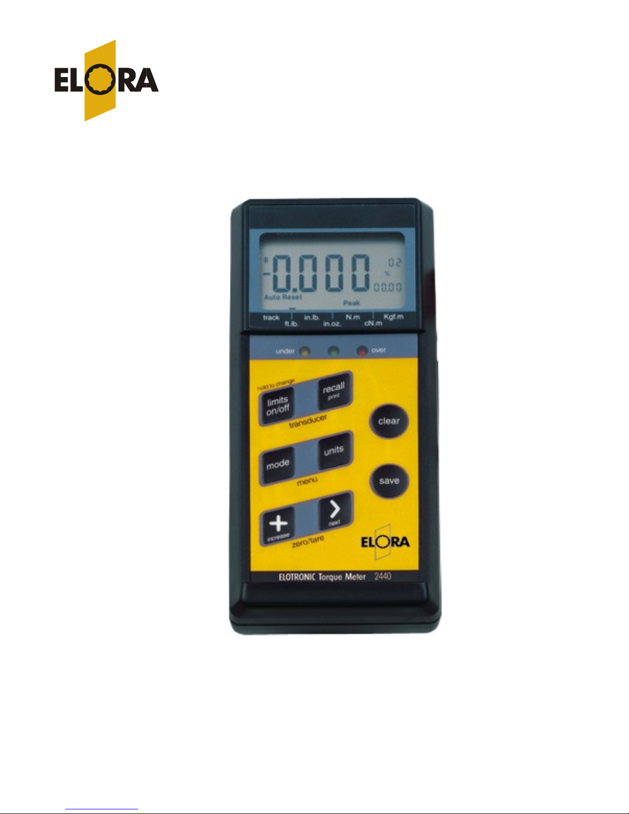
ELECTRONIC TORQUE METER ETM
OPERATION INSTRUCTION
Please read instruction carefully prior to first use!
ELORA Werkzeugfabrik GmbH l Am Blaffertsberg 33 l D-42899 Remscheid
*12 02 62 l D-42872 Remscheid l ( ( 49 ) 02191 / 5627-0 - Fax 5627-19
eMail: info@elora.de Homepage: www.elora.del
Page 2

! Always wear safety glasses when operating this torque meter.
! Always use the proper range transducer for the application. Over torque
may result in damage to the transducer or breakage resulting in personal
injury. Under torque may result in an incorrectly tightened fastener that
could loosen resulting in failure at a later date.
! Do not use a transducer if it has been over-torqued.
! Never apply torque in a situation where tool breakage may result in a fall or
slip resulting in personal injury. Pulling on the wrench, as opposed to
pushing on the wrench may help avoid this situation.
! Always replace worn or rounded fasteners prior to applying torque. Slippage
may occur resulting in personal injury.
! Never try to recharge a non rechargeable battery.
! Never mount a transducer to a bench that is unstable or will tip when a
torque is applied.
! Never use a torque transducer with an impact wrench.
Safety Warnings
1
Page 3

Introduction
The ELORA Electronic Torque Meter is a highly accurate torque analyzer and
production tool. Use it as a high end torque calibrator or bring it to the work
site to accurately apply torque to fasteners.
With the ELORA Electronic Torque Meter you only have to buy one
electronic module. Simply add ranges as you need them by purchasing
additional torque transducers.
You can use the 1% torque extensions to apply torque, check torque and also
to check torque wrenches. If you need more accuracy you can add the .5%
bench type transducers. These transducers are perfect for any calibration lab.
This Torque Meter uses the very latest in computer technology including a
small microchip installed on each transducer for true “plug and play”
recognition of the attached torque sensor. Simply attach the transducer, turn
the unit on and you are ready to go to work.
A full compliment of modes and functions combined with an easy to use
interface make this torque meter the perfect device for all torque applications.
There are some very special features inside of this meter that distinguish it
from the competition. For example, there is a “first peak” mode that allows
you to test and calibrate micrometer (clicking) type torque wrenches.
However, just having this software mode is not enough, you must also have
circuitry that is fast enough to capture the fast “click” of a torque wrench or
the ultra fast torque peaks of DC tools and pulse tools when in peak mode
(always use a joint rate simulator when testing power tools, joint rate
simulators simulate the application with springs).
The sampling rate of this torque meter is over 8,000 samples per second
rivaling any torque data acquisition system.
Memory for up to 1350 torque data combined with a direct rs232c com port
make this small unit a powerful data acquisition system.
Additionally, the torque meter has an industry leading triple 4 digit numeric
display that shows you the limits settings at all times and prompts you with
information during set-up.
These features combines with many other useful functions will make this the
last electronic torque meter you will ever need!
Thank you for purchasing the ELORA Electronic Torque Meter.
2
Page 4

Table of Contents
Feature Overview....4
Keypad functions....
To change the mode of operation....7
To change the units of measure....7
To turn limits on/off....7
To set a new target torque when % is the default.....8
To recall the last cleared torque....8
To save a torque value to memory....8
To view the attached transducer information....8
Menu Functions
To enter the menu mode....9
To recall memory.... 9
To change the % tolerance value....11
To make high low limits the default tolerance method....11
To change the display clear (reset) method....12
Entering the limits value....12
Power Standby Mode ....12
Entering Numbers....13
Zeroing the Display....13
Torque Sensors (transducers) and Overload ....14
Transducer Mounting Positions ....15
Checking for Accuracy ....16
Calibrating and bypassing the smart transducer calibration data....18
Selecting Custom Transducers ....20
Printing and Sending Data....20
Battery and Power....21
Specifications....22
.5
General Operation
Suggested mounting positions....6
Quick Start....7
To send memory to a printer or computer....10
To erase memory....10
To set filters....10
3
Page 5
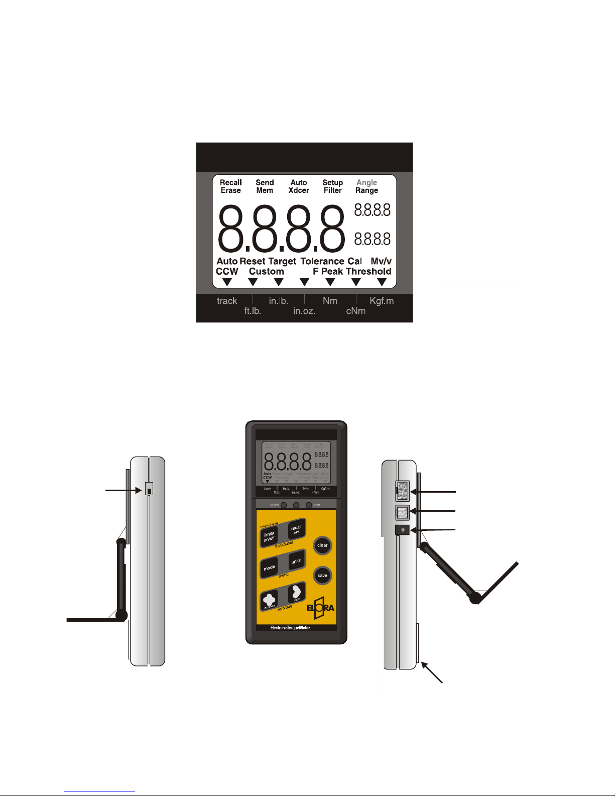
User Friendly LCD with
Industry leading triple
numeric display
Hi/Low
or %
tolerance
shown at all times
%
Track
Peak
and
First peak mode
Three reset
modes:
Auto
Manual
Timed
Custom transducer mode
allows easy adaptation
to third party transducers
Software selectable filters
Auto convert
engineering units
Super large
5/8 high digits
Memory for up to 1350
torque data.
External power
Rs232 port
Transducer input
Fully adjustable
stand/swivel mount
Easy access
9 volt battery
compartment
On/Off
switch
High impact plastic case
with sealed membrane
keypad
Features
4
2440
Page 6

Press once to turn limits on or off
Press and hold to set new limits
Press to change modes
(press save key to save new mode)
Recall last cleared torque
Press and hold to send data on display
to computer or printer
Press to view current torque in other units
Increases value of blinking digit
when setting numbers.
Selects next digit when setting numbers
Selects next function when in Menu mode.
Scrolls through data in memory when recalling memory
Clears data
on display
Saves data on display or
Selects the current function
when in menu mode
Press together to view the attached
transducer data
Press together to enter menu (set-up) mode
Press together to zero the meter
Keypad Functions
5
Page 7
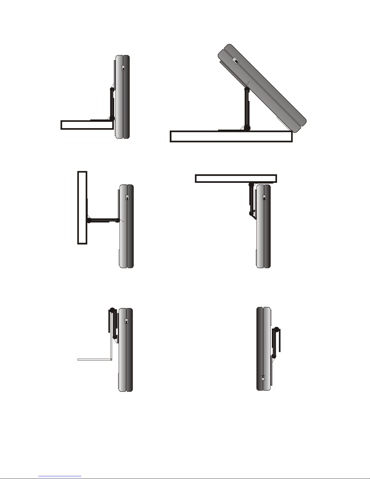
Belt mount
Suggested mounting positions
Loosen the 4 locking screws prior to adjusting
Reverse bracket and
hang on a thin shelf
Typical bench mounting
Vertical wall
Under a shelf
Over a ledge
6
Page 8
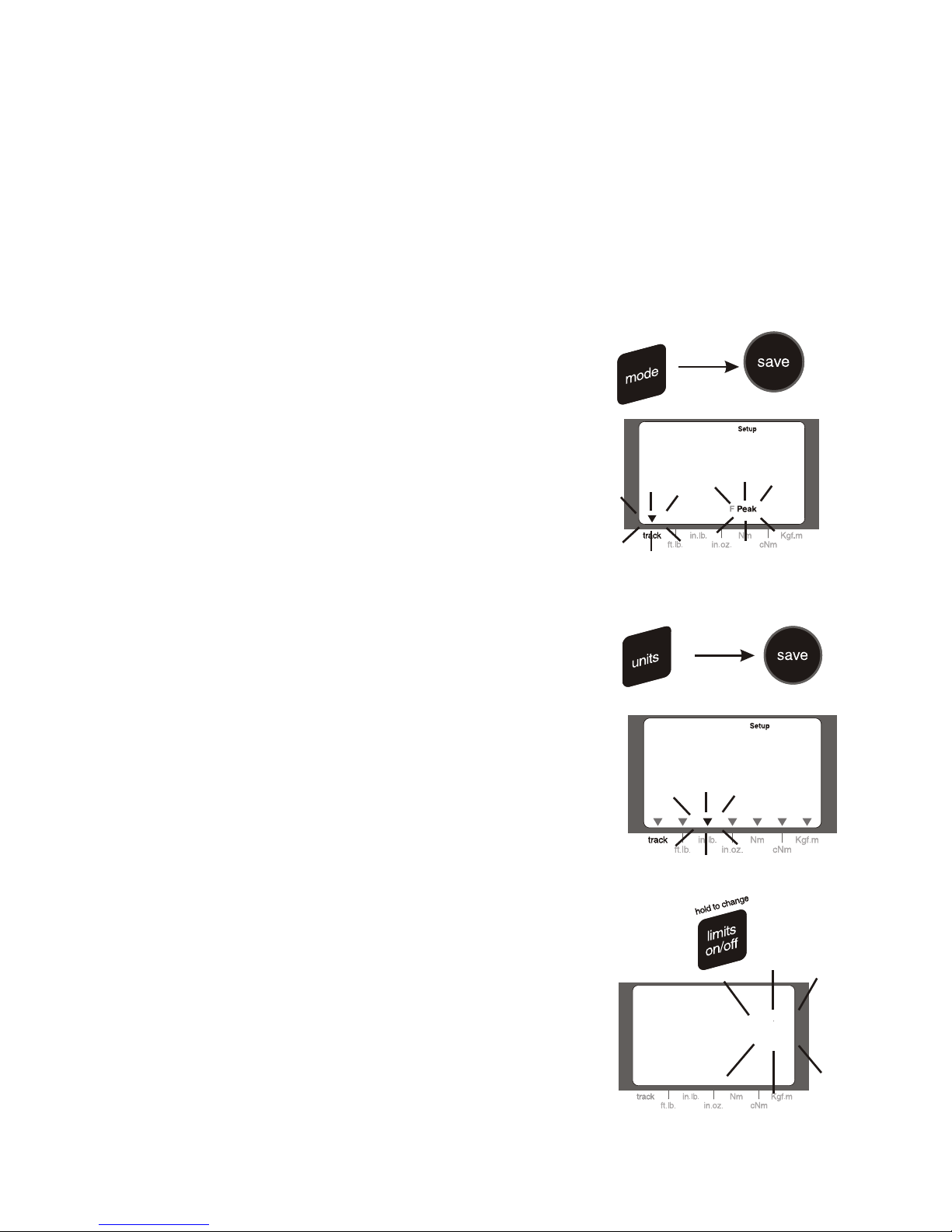
To change the mode of operation
1. Press the mode key until “peak”, “track” or “fpeak”
shows.
2. Press the save key to accept the new mode.
Track mode displays the torque as it increases and
decreases.
Peak mode tracks up but will hold on the peak value.
Fpeak (first peak) mode will capture the click point of a
micrometer torque wrench and disregard further input.
This mode is used to test and calibrate click type torque
wrenches.
To change the units of measure
1. Press the units key until the arrow points to the desired
units (the set-up icon will also be on).
(EEEE will show if units are out of range for the transducer
attached).
2. Press the save key to select the new units of measure.
Note: When you change the units of measure the limits
values (target or high and low) will be re-set to zero.
To turn limits on/off
1. Press limits key once to turn on.
2. Press the limits key again to turn off.
Note:
You will see the limits value in the secondary set of digits“%” and the current target torque will show if % is the
default or high and low arrows with the actual high and
low values if the high and low method of limits is selected
(see menu functions below to select the different methods).
%
04
100.0
Quick Start:
1. Turn off the power.
2. Plug in the proper range transducer- Turn on-wait for the display to show zero
(do not apply torque during this time). The meter reads the transducer smart chip when turned on.
3. Apply torque, (see warnings) you will see the reading increase as you increase the torque.
4. Clear the display with the clear key.
Or
5. Save torque to memory with the save key.
General Operation
7
Page 9

%
%
04
100.0
To set a new target torque
(When % is the default limits mode)
1. Press and hold the limits key for 1 second.
(The current target torque shows with the first digit
blinking).
2. Use the increase and next key(s) to set the new target
torque (see “entering numbers” below).
3. Press the save key to accept the new target torque.
Note:
You will see the new target torque displayed in the
secondary set of digits when the limits mode is on. This
value will remain, even after turning the unit off, until you
either change the units of measure or plug in a new
transducer.
To recall the last cleared torque value
1. Press the recall key.
2. Press the clear key when finished viewing and return to
operation.
Note:
You can press the save key to save the recalled torque
value before pressing the clear key. This allows you to
recall and save a value that may have been accidentally
cleared prior to saving.
To save a torque value to memory
1. Press the save key to save the displayed torque value to
memory.
Note: If you press the save key when zero is displayed
you will store the zero value in memory.
To view the attached transducer information
1. Press the transducer keys.
2. Press clear when finished viewing the data.
Note:
The range is in the upper right digits.
The MV/v (cal factor) is in the lower digits.
Smart Transducers will show “Auto Xducer”
50.00
2.000
0
0
0
0
OR
8
Page 10

Menu functions:
1. Activate the menu function by pressing the mode and
units key at the same time (the display will show set-up).
2. Press the next key to step through the various options.
Press the save key to select the option that is displayed.
To recall memory
1. Press menu keys (set-up icon comes on).
2. Press the next key once or until the ”recall mem” icon is
on (if you miss keep pushing the next key until “recall
mem” shows.
3. Press save to select (SEL) the recall memory option.
The number of data in memory now shows.
4. Press the next key to view the data (press the increase
key to view the previous torque data).
5. Press the clear key when finished.
Note: The data number is shown in the upper right digits.
0005
35.50
0005
9
Page 11

To Send Memory to a printer or computer
1. Attach the torque meter serial communication
cable to your printer or computer com port. (set the
baud rate to 4800,8,n,1,hardware). refer to your
computer manual for details on how to
communicate with serial devices.
2. Press the menu keys.
3. Press the next key twice or until the display
shows send memory.
4. Press the save key to select the send memory
option.
5. The data in memory will now be sent (the data
number will count down as the data is sent out the
serial port.
See “printing and sending data” later in this
manual for more information.
To Erase Memory
1. Press the menu keys.
2. Press the next key three times or until the
”Erase mem” icon shows.
3. Press the save key to select the erase memory
function (the display will blink giving you a
second chance to decide if you really want to erase
memory).
4. Press the save key again to confirm and erase
the memory or clear to exit without erasing
memory.
To Set filters (500hz is common for hand
tool operations)
1. Press the menu keys.
2. Press the next key four times or until “filter” is
shown.
3. Press the save key to select the filter function.
4. Press the next key until the desired filter is
shown.
5. Press the save key to store the new filter
setting.
Note:
The standard filter setting is 500 Hz for hand type
applications and 1500 Hz for power tool
applications. Filters are used to “screen” out any
non-torque noise or vibration that may be input
from a high speed power tool. Use a lower filter
setting if you are getting occasional spikes in the
reading.
0005
Exit without erasing
Erase Memory
or
500
SEL 3
1000
SEL 4
Select
Filter 3
500 Hz
…
10
send
Page 12
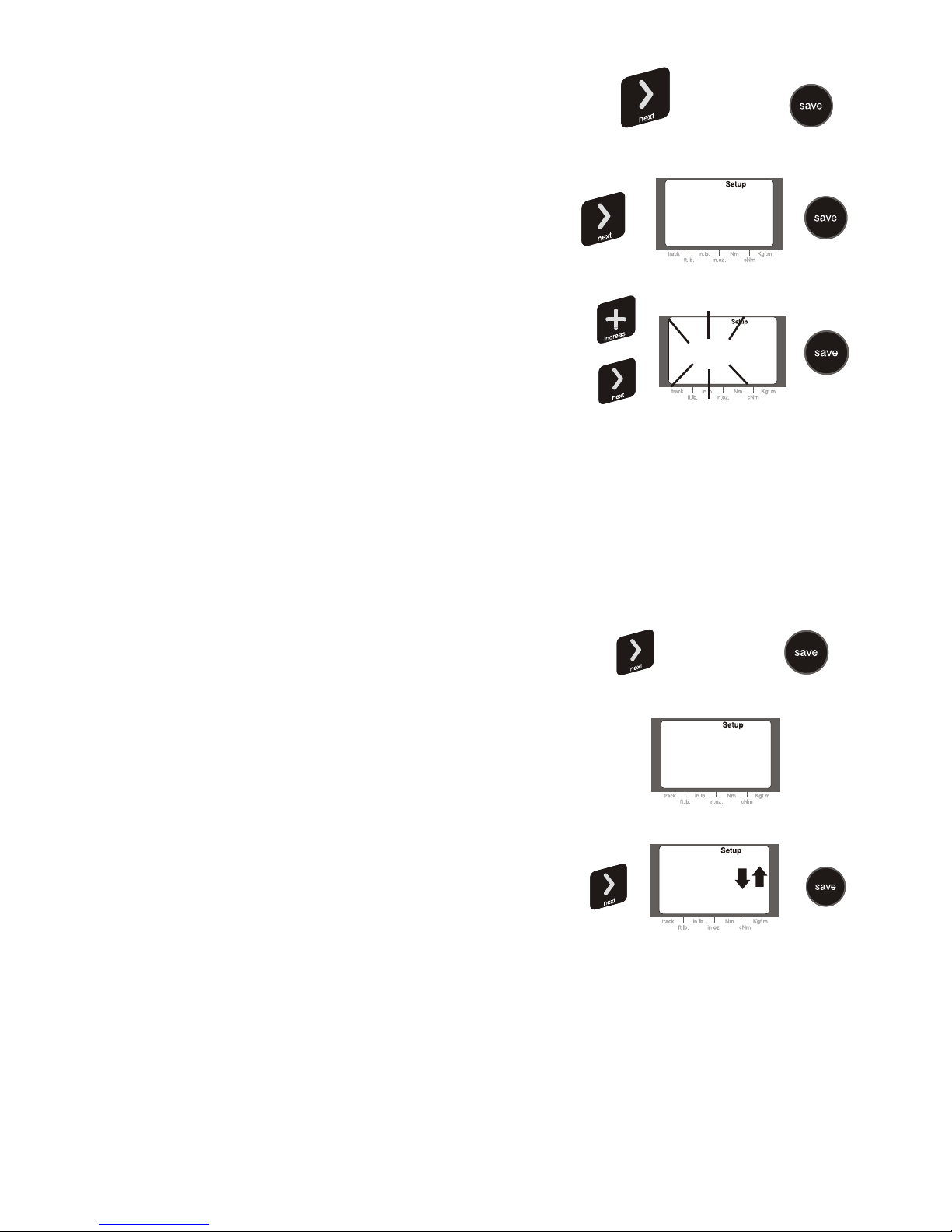
To change the % tolerance value from the
current setting
1. Press the menu keys.
2. Press the next key 5 times or until “tolerance”
shows.
3. Press the save key to select the tolerance
function.
4. Press the next key until “% On” shows.
5. Press the save key.
6. Enter the new % value (01-99%) with the
increase and next keys (see “entering numbers”
below).
7. Press the save key when the value is correct.
To make high/low limits the default
tolerance mode
1. Press the menu keys.
2. Press the next key 5 times or until
“tolerance” shows.
3. Press the save key to select the tolerance
function.
4. Press the next key until the high/low arrows
show.
5. Press the save key to store the new tolerance
setting.
Note:
Once you change the tolerance mode it will
become the new default tolerance mode each
time the torque meter is turned on.
Now when you set the limits (press and hold the
limits on/off key) you will be prompted to set the
high and low limits instead of the target torque.
On
02
%
%
On
%
On
…
11
Page 13

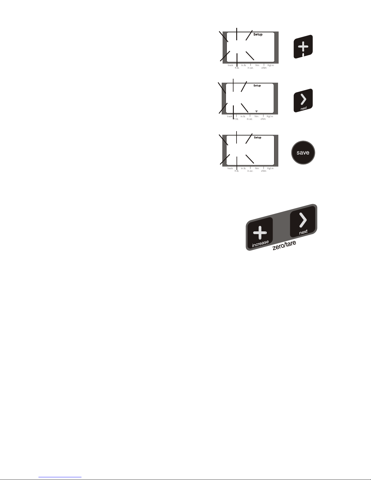
To change the display clear method
1. Press the menu keys.
2. Press the next key 6 times or until the “Auto
Reset” icon shows.
3. Press the save key to select the Auto Reset
function.
4. Press the next key until:
“AUt0” shows (Auto sense)
“Off” (manual clear using the clear key)
“1…….9” (seconds before the display clears
itself)
5. Press the save key to store new setting.
Note:
If auto sense is selected the torque meter will
automatically clear the display when a new torque
cycle begins. This means that you do not have to
continually reach up and clear the display manually.
Entering the limits (tolerance) settings.
1. From the operation mode press and hold the
limits on/off key.
If you have set the % function set then the meter
will prompt you to enter the target tolerance (it will
automatically calculate the limits).
If you have the high/low function set then the meter
will first prompt you to enter the low limit and then
the high limit.
Power saving standby mode
When the torque meter has not been used for
approximately 3 minutes it will go into the power
down or “standby” mode. The display will show
“. . .”.
Press the clear key to get back to normal
operation. For the longest life from the batteries turn
the meter off when not used.
. . .
…
…
AUto...OFF...1sec.....9sec
hold to change
12
Page 14
Entering Numbers
When a number needs to be entered, a default
value (or the last value entered) will be shown.
The digit that can be changed will blink.
Press the increase key to increase the value of
the blinking digit.
Press the next key to go to the next digit.
Press the increase key to increase the value of
the next blinking digit.
Repeat for digits 3 and 4.
When the number is correct, press the save key
to save the new value.
Zeroing the display
If you press the increase and next keys at the
same time you will “Zero” the unit. Make sure
that there is no load on the transducer when
pressing the zero keys. The meter will not read
torque until approximately 2% of the transducer
range has been reached, therefore you must zero
the unit even when the display shows zero.
IMPORTANT!
Always zero the unit when changing direction.
If you plan to use the meter in the
counterclockwise direction load the transducer
three times in the counterclockwise direction (to
full scale) and then zero the display. Press the
zero keys even if the display shows “000.0”
This will compensate for small amounts of
hysteresis (hysteresis is a natural characteristic
of steel).
0005
000.0
100.0
100.0
13
Page 15

Torque Sensors and OVERLOAD
Torque transducers are designed to give years of reliable operation if treated properly.
Torque transducers are sensitive electro-mechanical measurement devices and should
be handled with care.
Never over-torque a transducer beyond its usable range. It is good practice, when
possible, to select a transducer that is at least 25% greater in range than the expected
torque it will apply. This may help avoid accidental over-torque.
The torque transducers that are supplied with the torque meter will accept up to 50%
over torque without damage. However, if this should occur we recommend that you
return the unit for a calibration check.
The torque meter has an audible warning system that will alert you if you have
exceeded the usable range of the transducer. A constant beeping sound will occur.
Stop applying torque when you hear this sound, and press the clear key to stop the
buzzing.
Cable pointing down
Correct position for testing torque extensions
Cable
Cable
F
Mount this end
Attach arm this end
14
Page 16

Transducer mounting positions
for bench top style torque transducers:
Warning!
Always make sure the bench is strong enough and will not tip wen applying torque
Bolting the bench to the ground may be necessary on higher range transducers.
Make sure the cable is pointing down (4 O’CLOCK POSITION) when mounted on a
bench. This will place the primary axis in the correct position.
3” bolt circle for 3/8 inch screws
or
2.175” bolt circle for ¼ inch screws
15
Page 17

Checking for accuracy
The Torque Meter and torque transducers are factory calibrated and should be
checked on a regular basis. We recommend that, provided the transducers are used
according to this manual, they be re-certified yearly. Since the frequency of use,
among other factors, may affect the calibration, the user must determine the best
calibration interval.
It is important to use the correct arm length since arms that are too short may
create excessive bending loads.
Recommended torque arm lengths:
4” 100 in lb
10” 250 in lb and 50 ft. lb.
24” 150 and 250 ft.lb.
48” 500 ft. lb.
These arm lengths closely represent the length of typical wrenches that will be
used on the transducers. They also allow for no more than 150 lbs of weights,
which also represents the “typical” amount of force required to generate the torque
with a wrench. Do not use a 10” arm to calibrate a 250 ft. lb. wrench. This would
require 300 lbs of weights, this is not good for the transducer and is not
representative of the typical weight needed to generate 250 ft.lb. applied by a
person. Most conventional torque wrenches are designed to be long enough to
allow a 150-175 lb person to generate the force required to generate the needed
torque. Using the above arm lengths will be consistent with this philosophy.
The accuracy of the meter is such that any incorrect zero caused by out of balance
arms, mis-alignment or sloppy adapters used on the torque arm system may cause
a “perceived”out of tolerance situation. This can happen when you use a female
drive torque arm on a female drive transducer and use a male-male adapter in
between. It can also happen when you use an adapter to reduce a ½” female drive
arm down to a 3/8” female drive using an off-the-shelf adapter. For this reason you
must always use the proper drive arm with the transducer. If the transducer is a ½”
female drive then you must use a ½” male drive torque arm.
Even benches that are not flat or deflect during high load calibrations are
unacceptable. In this case the transducer will not be perpendicular with the
weights and this will show on the meter (yes the meter is that sensitive), resulting
in a possible out of tolerance condition.
16
Page 18

Procedure for checking accuracy
Transducers are calibrated to within .5% (bench type) or 1% extension type
IV +/- .1 at the factory. If you require greater accuracy you can bypass the
smart chip in the transducer and perform a manual calibration on
transducers. This will account for variations in torque arm calibration
systems.
IMPORTANT!
YOU MUST ALWAYS DO THE FOLLOWING:
MOUNT THE TRANSDUCER SO THE CABLE IS POINTING DOWN.
PUT THE METER IN TRACK MODE.
1. NEVER USE A TORQUE ARM THAT IS NOT BALANCED ABOUT ZERO. A
HIGH PRE-LOAD,OR AN OPPOSITE DIRECTION PRE-LOAD REDUCES
ACCURACY AND IS NOT INDICATIVE OF REAL APPLICATIONS. A SLIGHT
PRE-LOAD MAY, HOWEVER, BE NECESSARY TO TAKE UP DRIVE
TOLERANCES IN THE DIRECTION TO BE TESTED. A 1 OR 2 LB HANGER
WEIGHT SHOULD BE SUFFICIENT.
2. ALWAYS APPLY FULL SCALE TORQUE, THREE TIMES, WITH WEIGHTS,
IN THE DIRECTION YOU ARE TESTING PRIOR TO RUNNING AN
ACCURACY TEST.
3. AFTER STEP 2 ABOVE, WAIT AT LEAST 30 SECONDS OR FOR THE
WEIGHT HANGER TO STABILIZE. SWINGING HANGERS WILL GIVE AN
INCORRECT ZERO READING AND MAY THROW OFF ACCURACY.
4. AFTER STEP 3 ABOVE PRESS THE ZERO BUTTONS (EVEN IF THE
DISPLAY SHOWS “000.0”) DO NOT PRESS THEM AGAIN UNTIL YOU START
A COMPLETE NEW TEST CYCLE (STARTING FROM STEP 1 ABOVE).
5. AFTER STEP 4 ABOVE APPLY 10% LOAD, LET THE HANGER STABILIZE
AND CHECK READING. DO NOT REMOVE THE WEIGHTS WHEN FINISHED
CHECKING AT THIS POINT.
6. AFTER STEP 5 ABOVE APPLY ADDITIONAL WEIGHTS TO THE HANGER
TO BRING THE TORQUE TO 50% OF LOAD AND CHECK READING. DO NOT
REMOVE THE WEIGHTS WHEN FINISHED CHECKING AT THIS POINT.
7.
Calibrating the torque transducer:
AFTER STEP 6 ABOVE APPLY ADDITIONAL WEIGHTS TO THE HANGER
TO BRING THE TORQUE TO 100% OF LOAD AND CHECK READING.
THE MAJORITY OF ACCURACY PROBLEMS OCCUR DUE TO INCORRECT
LOADING SEQUENCE, ZERO PROCEDURES AND TORQUE ARMS THAT
ARE NOT IN BALANCE WITH A SLIGHT PRE-LOAD IN THE DIRECTION TO
BE CHECKED.
17
Page 19

You can not change the information on the smart chip within the transducer. If the values
on the chip need to be changed then one of two things MAY have happened:
1. The torque arm system, or the procedure, is introducing errors that when added are
creating an out of tolerance situation (SEE ACCURACY CHECKING ABOVE)..
2. The transducer has been damaged and needs repair (usually shown by significant
errors).
Bypassing the smart transducer feature.
If you want to bypass the smart chip calibration data, and use the calibration data that
you create with your torque arms, you can do so by assigning a “custom” transducer
number to the transducer and manually calibrating it using your own dead weight system.
This method stores the calibration data for the transducer in the memory of the meter, not
in the memory chip inside the transducer. In order to use the custom transducer data you
must select the custom transducer number when you power on the unit (see selecting
custom transducers below). If you do not select the custom transducer number the meter
will revert to the calibration data on the chip inside the transducer.
You can tell if the system is using the smart chip inside the transducer if, after pressing
the transducer keys you see the words “auto Xducer”. You will see the words “custom”
transducer if you have selected the transducer manually.
This method can be used to “fine tune” a transducer, possibly resulting in higher accuracy
and can also used for calibrating third party transducers to the torque meter.
To manually calibrate a “custom” transducer
1. From normal operation mode press the menu buttons
2. Press the next key until the word “CAL” is displayed. Press the save key to select
the cal option.
The current default custom transducer number (01 to 15), will show and flash (unless it
is a smart transducer in which case you must press the next key to select a custom
transducer number).
Press the next key until the desired custom transducer number is shown (mark this
number on the transducer for future reference).
Note: The current transducer settings for the transducer number will show as you scroll
through the transducers, all default values are “9999” or “1000” and 2.000 Mv/v.
Press the save key to select the desired transducer number.
The current full-scale range will now be displayed (will default to “9999” if this number
has never been assigned) with the first number flashing (do not worry about the position
of the decimal, that will be set next).
3. Press the increase and key to make the digits read the full-scale range of the transducer
you are going to calibrate. Press the save key
4. Now set the decimal position with the next key (keep pressing until you see the
decimal point)..
Press the Save key.
5. Set the units by pressing he units key. Press Save.
18
Page 20

6. Set the estimated clockwise (cw) Mv/v (if known, use 2.000 if not known). Press Save.
7. Set the Counterclockwise (ccw) Mv/v (if known, use 2.000 of not known). Press Save.
8. The display will now show “calc” (more on “calc” later). Press the next key until the
unit shows “cert”. which means you are going to calibrate (certify) a transducer with dead
weights.
The display will now show “CCW CAL0” This means it is ready to take a
counterclockwise zero reading.
SEE ACCURACY CHECKING PROCEDURES FOR THE PROPER METHOD TO
LOAD A TRANSDUCER.
9. Load the transducer, with a balanced arm and a slight pre-load, in the counter clockwise
direction three times to full scale with dead weights, and remove the weights but not the
arm and pre-load hanger. Wait 30 seconds or for the hanger to settle and press the Zero
buttons (even if the display shows 000.0).
The Display will now show “CCW FS” which is prompting you to apply the Full-Scale
weights to the arm in the counterclockwise direction.. Apply the full-scale weights in the
counterclockwise direction, stabilize the weights and press the save key.
Make the display read the full-scale counterclockwise value (within tolerance) with the
increase and next keys. Press the save key.
10. The display will now read “CW CAL0”. This means the meter is ready to read the
clockwise zero reading.
The display will now show “CW FS” which means load the arm to full scale in the
clockwise direction. Press the save key.
Make the display read as close as possible to the full scale clockwise value by pressing the
increase and next keys.
Press the save key.
You will now exit and be in the track mode with the display reading the calibrated full
scale clockwise value. The calibration data you just created will be saved in the memory of
the meter, under the custom transducer number you assigned to that transducer.
From now on, if you want to use the manual calibration values that you just entered you
simply need to select the proper transducer number when selecting custom transducers.
you do not have to re-select a smart transducer custom assigned number unless you have
disconnected the transducer from the meter.
You can repeat the above process adjusting the full scale value until the unit reads as
accurately as you desire at any point on the scale.
Selecting custom transducers:
Load the transducer, with a balanced arm and slight pre-load, in
the clockwise direction three times to full scale with dead weights, and remove the weights
but not the arm and pre-load. Wait 30 seconds or for the hanger to settle and press the
Zero buttons (even if the display shows 000.0).
19
Page 21

If you have a non-smart custom transducer that you have calibrated manually, per the
above procedure, the meter will automatically recognize that the attached transducer is
not smart and prompt you with a transducer number every time you turn on the meter.
Simply press the next key to select the proper transducer number, then press save and
you will enter the normal operation mode. The meter will always turn on with this
transducer number active (on non-smart transducers) and will use the calibration data
that was entered during the manual calibration process.
If you have a smart transducer and have also assigned it a custom transducer number
you do not have to re-select the custom number as long as you do not detach the
transducer (even after power down). If you have detached the transducer then the meter
will re-read the smart chip and use the smart data, not the custom data, when it is turned
on. Select the custom transducer in this case. Do this by pressing the transducer keys
and pressing the next key until the display shows the transducer number you have
assigned to the transducer. Press the save key and the unit will now use the calibration
data that was stored in the memory of the meter for that transducer. Remember, you
only have to select the custom transducer number after you have detached the
transducer.
Printing and Sending Data
Note:
It is not within the scope of this manual to instruct the user on how to set his/her
computer or printer up for data transfer. Please refer to the operation manual of your
particular printer or computer.
The torque meter operates with an industry standard RS232C communication port. You
can use a program as simple as “Hyper terminal” that comes standard with Windows or
any third party data logging software.
The ELORA col that the torque meter sends data is as follows:
RS232C, 4800, 8, 1, n
Refer to your computer or printer operation manual for a description of these settings.
The torque meter will send data out the communication port under the following
circumstances:
When the save key is pressed the data on the display will be sent (and saved).
When the “send mem” function is selected, from the menu function, it will send all the
data in memory.
When the recall key is pressed and held for 1 second the torque meter will send the
torque value on the display.
Battery and Power
20
Page 22

The torque meter uses either a common 9 volt battery (gives longest life) or a
rechargeable 9 volt battery (supplied standard for convenience).
Battery life depends significantly on the type of battery used. Non-rechargeable lithium
ion 9-volt batteries may last up to 40 hours. Common alkaline batteries may last up to
20 hours.
It is recommended that if you are going to use the meter on battery power that you keep
a standard 9 volt battery as a backup, or an additional charged 9 volt battery. Any
common re-chargeable 9 volt battery can be used in the torque meter.
The Torque meter has a power down (standby) mode that will activate after
approximately 3 minutes without use. This mode still uses battery power.
Press the clear key to resume operation when the power down mode is active (depicted
by “…” on the display). The sleep mode still takes power so if you are on battery power
it is best to turn the meter off when not in use, this will result in longest battery life.
The torque meter will show a “B” icon on the display when the battery is low and will
show a “B” with two dashes “- -“ on the main digits when the batteries are critically low.
The time between low battery and critically low battery may vary depending on the state
and type of battery.
The torque meter can be used while the batteries are charging with no adverse effect.
The supplied power adapter is a trickle charger that will take at least 14 hours to charge
a 9 volt battery. You can use any standard external quick charger to charge the 9 volt
battery.
+
Make sure battery is placed with + side
as shown
21
Page 23

Specifications
Range and Display: Direct reading triple numeric LCD display with large 4 digit
primary display (5/8” high) and two additional 4 digit displays.
Maximum reading 9999.
Floating Decimal Point.
Accuracy : : When used with:
Smart Bench top: .5% IV from 10 – 100 % of transducer range +/- .1.
Smart Extension: 1% IV from 10 – 100% of transducer range +/- .1.
Greater accuracy may be achieved with manual calibration.
Sampling Rate: Approx. 8,000 samples per second.
Power: Battery: common 9 volt - ( rechargeable NiCd supplied for
convenience).
Battery life: Up to 20 hours with standard 9 volt battery under normal
use*.
Recharging Circuit: Internal. 110 volt input, 9 volt 300 mA output, adapter supplied
standard (center positive 2.1 mm connector).
Meter Case: Dimensions: 7.25” long x 3.25 “ wide x 1.25” thick.
Weight: Less than 8 ounces
Stand: Folding and adjustable bench, wall or shelf stand supplied standard.
Memory: Up to 1,350 torque data. Includes data number, torque value and units.
Communication: Direct to serial computer or printer.
ELORA col: RS232C 4800 BPS, 8, 1, n.
Communication cable and adapter supplied standard.
Operating Modes: Track, Peak and First Peak for calibration of Micrometer (clicking)
torque wrenches.
Limits setting: Tolerance values displayed on triple numeric display during operation.
Quick on/off with one key.
User selectable % (1-99%) with programmable target.
or
Programmable high and low values.
Tolerance prompting: Triple lights and buzzer: Yellow (under), Green (within), Red (over)
Tolerance values displayed on triple numeric display during operation.
Display Clear Modes: Automatic cycle complete.
Programmable timed auto reset from 1 – 9 seconds.
Manual Clear.
Filters: 5 user selectable filter settings: 170hz, 250 Hz, 500 Hz, 1500 Hz,
3600 Hz.
Transducer Selection: Automatic “plug and play” with smart chip.
or manual “custom calibration”.
* Battery life will vary depending on quality of battery and usage-values estimates only.
Longest life will come from a lithium ion 9 volt battery.
22
 Loading...