

EL-O-MATIC POSIFLEX F20 Installation And Operation Manual
DOC,F20,EDN Rev. : -
Installation and Operation
Manual
Electro-Pneumatic Positioner F20
Accredited by the
Dutch Council for
Certification
English
Deutsch
Nederlands

2 DOC,F20,EDN Rev.: -
Contents (English)
1.0 Introduction .................................................................. 4
1.1 Product Description F20 ....................................... 4
1.2 Operating Principles .............................................. 6
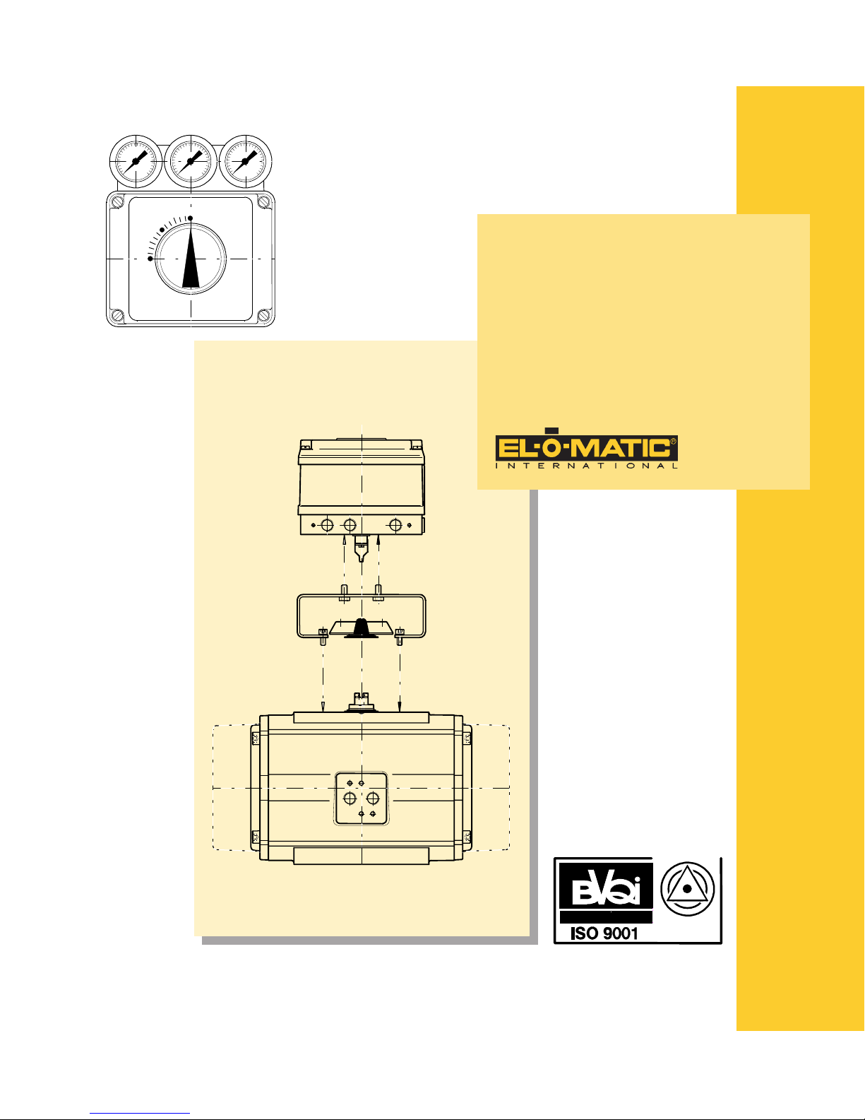
2.0 Installation - Rotary Actuators ................................... 8
2.1 Mechanical Installation - Rotary Actuators............. 8
2.2 Pneumatic Connections ....................................... 10
2.2.1 Double acting....................................................... 10
2.2.2 Single acting ........................................................ 10
3.0 Installation - Linear Actuators .................................. 12
3.1 Mechanical Installation - Linear Actuators ........... 12
3.1.1 Installation sequence ........................................... 12
3.2 Pneumatic Connections ....................................... 14
3.2.1 Double acting....................................................... 14
3.2.2 Single acting ........................................................ 14
4.0 Electrical Connections - Initial Setup....................... 16
4.1 Electrical Connections ......................................... 16
4.2 Initial Setup - Zero, Range and Sensitivity ........... 16
4.3 Zero Setting ......................................................... 16
4.4 Range Setting ...................................................... 16
4.5 Sensitivity Setting................................................. 16
4.6 Split range setting ................................................ 18
5.0 Failure Modes............................................................. 20
5.1 Failure Modes - Doub le acting ............................. 20
5.1.1 Changes for Re verse Acting ................................ 20
5.2 Failure Modes - Single Acting (Spring return) ...... 22
5.2.1 Changes for Re verse Acting ................................ 22
6.0 General specifications .............................................. 24
6.1 Certificates .......................................................... 25
7.0 PTF20 option .............................................................. 26
7.1 Introduction .......................................................... 26
7.2 Installation............................................................ 26
Inhalt (Deutsch)
1.0 Einführung ............................................................................. 5
1.1 Produktbeschreibung F20 .............................................. 5
1.2 Arbeitsweise ................................................................... 7
2.0 Einbau Drehantriebe............................................................. 9
2.1 Mechanischer Einbau - Drehantriebe ........................... 9
2.2 Pneumatikanschlüsse ................................................... 11
2.2.1 Doppeltwirkende Ausführung ..................................... 11
2.2.2 Einfachwirkend Ausführung........................................ 11
3.0 Einbau - Hubantriebe ......................................................... 13
3.1 Mechanischer Einbau - Hubantriebe ........................... 13
3.1.1 Montageablauf ............................................................. 1 3
3.2 Pneumatikanschlüsse ................................................... 15
3.2.1 Doppeltwirkende Ausführung ..................................... 15
3.2.2 Einfachwirkende Ausführung ...................................... 1 5
4.0 Elektrische Anschlüsse - Anfangseinstellungen ................ 17
4.1 Elektrische Anschlüsse ................................................. 17
4.2 Anfangseinstellungen - Null, Bereich und Totzone ..... 17
4.3 Nullpunkteinstellung .................................................... 17
4.4 Bereicheinstellung ........................................................ 17
4.5 Einstellung der Empfindlichkeit .................................. 17
4.6 Einstellung für geteilten Eingangsbereich / Split range 19
5.0 Ausfallarten ......................................................................... 21
5.1 Ausfallarten Doppeltwirkend....................................... 21
5.1.1 Umschaltung auf umgekehrte Wirkung ....................... 21
5.2 Ausfallarten - Einfachwirkend (Federrückführung) .... 2 3
5.2.1 Umschaltung auf umgekehrte Wirkung ....................... 23
6.0 Allgemeine technische Daten .............................................. 24
6.1 Zertificate ..................................................................... 25
7.0 Optionsbaugruppe PTF20 .................................................. 27
7.1 Einführung ................................................................... 27
7.2 Einbau .......................................................................... 27
Inhoud (Nederlands)
1.0 Introductie .................................................................... 5
1.1 Produktomschrijving F20 ....................................... 5
1.2 Werkingsprincipes ................................................. 7
2.0 Montage op roterende aandrijvingen ......................... 9
2.1 Montage op roterende aandrijvingen ..................... 9
2.2 Pneumatische aansluitingen ................................ 11
2.2.1 Dubbelwerkende uitvoering ................................. 11
2.2.2 Enkelwerkende uitvoering.................................... 11
3.0 Montage - lineaire aandrijvingen .............................. 13
3.1 Montage - lineaire aandrijvingen .......................... 13
3.1.1 Montagevolgorde ................................................. 13
3.2 Pneumatische aansluitingen ................................ 15
3.2.1 Dubbelwerkende uitvoering ................................. 15
3.2.2 Enkelwerkende uitvoering.................................... 15
4.0 Elektrische aansluitingen - Initiële instelling .......... 17
4.1 Elektrische aansluitingen ..................................... 17
4.2 Initiële instelling - nulpunt, bereik en gevoeligheid 17
4.3 Nulpunt instellen .................................................. 17
4.4 Instellen van het bereik ........................................ 17
4.5 Instellen van de gevoeligheid ............................... 17
4.6 Instellen voor gesplitst bereik............................... 19
5.0 Storingen .................................................................... 21
5.1 Storingen - dubbelwerkend .................................. 21
5.1.1 Wijzigingen voor omgekeerde werking ................ 21
5.2 Storingen- enkelwerkend (veerretour) ................. 23
5.2.1 Wijzigingen voor omgekeerde werking ................ 23
6.0 Algemene specificaties ............................................. 24
6.1 Certifikaten .......................................................... 25
7.0 Optie PTF20................................................................ 27
7.1 Inleiding ............................................................... 27
7.2 Installatie.............................................................. 27

3DOC,F20,EDN Rev.: -
WARNUNG
Das Gerät darf nur von Fachpersonal, das mit der Montage, der Inbetriebnahme und dem Betrieb dieses Produktes vertraut ist, montiert und in Betrieb genommen werden.
Fachpersonal im Sinne dieser Einbau- und Bedienungsanleitung sind Personen, die auf Grund ihrer fachlichen Ausbildung, ihrer Kenntnisse und Erfahrungen sowie ihrer
Kenntnisse der einschlägigen Normen die ihnen übertragenen Arbeiten beurteilen und mögliche Gefahren erkennen können.
Bei Geräten in explosionsgeschützter Ausführung müssen die Personen eine Ausbildung oder Unterweisung bzw. eine Berechtigung zum Arbeiten an explosionsgeschützten Geräten in explosionsgefährdeten Anlagen haben.
Gefährdungen, die am Stellventil vom Durchflußmedium, dem Stelldruck und von beweglichen Teilen ausgehen können, sind durch geeignete Maßnahmen zu verhindern. Sachgemäßer Transport und fachgerechte Lagerung des Gerätes werden vorausgesetzt.
Die elektrische Sicherheit wird allein durch die speisenden Geräte bestimmt, da im Gerät nur Kleinspannungen zur Anwendung kommen. Bei der elektrischen Installation
sind die geltenden Vorschriften zu beachten. Zusätzlich sind bei der Installation von explosionsgefährdeten Geräten die Angaben der Konfo rmitätsbescheinigung und die
Vorsch riften für die Errichtung explosionsgefährdeter Anlagen zu beachten.
Waarschuwing
Dit apparaat mag alleen door vakpersoneel, welke met de montage, het in bedrijf stellen en het in bedrijf zijn, bekent zijn, gemonteerd en in bedrijf genomen worden.
Vakpersoneel zoals in deze montage handleiding bedoelt, zijn personen, die op grond van hun vaktechnische opleiding, hun kennis en ervaring als ook
hun kennis van de desbetreffende normen de hun opgedragen arbeid kunnen beoordelen en de mogelijke gevaren kunnen herkennen.
Bij apparaten in explosieveilige uitvoeringen moeten die personen een opleiding of onderricht in resp. een bevoegdheid voor het werken met explosieveilige apparaten in omgevingen met dreigend explosie gevaar, hebben.
Gevaar, welke aan de regelklep van het doorstroommedium, de werkdruk, en de bewegende delen uitgaan, moeten door geëigende maatregelen verhinderd worden. Deskundig transport en vakkundige opslag van het apparaat wordt verondersteld.
De elektrische zekerheid wordt alleen bepaald door de voedende apparaten, omdat in het apparaat alleen laagspanning gebruikt worden. Bij de elektrische installatie moeten alle geldende voorschriften in acht genomen worden. Aanvullend moeten bij de installatie van apparaten met dreigend explosie
gevaar de aanwijzing van de konformiteitsgetuigschrift en de voorschriften voor het vestigen van een installatie met dreigend explosie gevaar in acht genomen worden.
Warning
The device may only be operated by craftsmen who are familiar with the mounting, the installation and operation of this product.
Craftsmen as mentioned in this installation and operation manual are persons who, on the basis of their crafts education, their knowledge and exper ience
as well their knowledge of the applicable standards can judge the to them commissioned labour and can recognise the possible dangers.
To work on the device in an explosion proof execution, the craftsmen must have an education or instruction respectively the legitimacy to work on
explosion proof devices in explosion hazardous areas.
Dangers due to the control valve of the flow media, the working pressure and the moving parts have to be avoided by appropriate measures. Professional
transport and storage of the device is required.
The electrical security will be determined by power supply, because in the device only low voltageis applied. The electrical installation has to comply with
the applicable standards. Additionally for the installation of explosion hazardous devices the notifications of the certificate of conformity and the
regulations for to establish explosion hazardous installations have to be obser ved.
4 DOC,F20,EDN Rev.: -
1.0 Introduction / Einführung / Introductie
1.0
1.1 Product Description F20
El-o-matic POSIFLEX positioners belong to the most advanced
positioners of their type on the market today. This latest version
is made possible by a combination of the new est electronics
developments with a high precision spool type pneumatic pilot
for the volume amplifier .
The F20 is a true 2 wire instrument: An industry standard 4 to
20 mA. signal pro vides both the controlling signal and the
power supply for the electronics. As such the positioner is plug
compatible with the current industry standard.
The use of electronics as the controlling element means that all
the usual control characteristics: Zero, range and sensitivity
are all electronically resettable using trimmers on the control
card.
Both rotary and linear applications are catered for, the difference being with feedback mechanism and the mounting
methods. A single univ ersal positioner is suitab le f or both
double acting and single acting (spring return) actuators. The
standard internal feedback provides a linear relationship
between the input signal and the output movement.
The functionallity of the F20 positioner can be extended by a
"Plug-in" PTF20 Option for a analog 4-20mA f eedback signal.
This option is, well protected, mounted inside the F20 enclosure and has its own feedback potentiometer.
ELECTRO-PNEUMATIC
POSITIONER
F20
Rotary
Linear
Closed
Open Open
Closed

5DOC,F20,EDN Rev.: -
1.0 Introduction / Einführung / Introductie
1.1 Produktbeschreibung F20
Die El-o-Matic POSIFLEX-Positioner gehören zu den fortschrittlichsten Stellungsreglern ihrer Art am Markt. Die letzte Ausführung
wurde möglich durch die Kombination der neuesten Elektronik-Entwicklungen mit einem Präzisions-Stahlschieberventil zur pneumatischen Ausgangsverstärkung.
Der F20 ist ein reines 2-Leitergerät, dessen 4-20 mA Eingangssignal
sowohl als Regelsignal als auch zur Energieversorgung der
Elektronikbaugruppe dient. Damit ist dieser Positioner kompatibel
zum aktuellen Industriestandard. Die Nutzung der Elektronik zur Informationsverarbeitung gestattet die Einstellung der üblichen Parameter Nullpunkt, Bereich und Verstärkung mittels Trimm-Potentiometer auf der Leiterplatte. Es sind Ausführungen sowohl für Drehantriebe als auch für Linearantriebe verfügbar, die sich nur im Rückführmechanismus und in der Montageweise unterscheiden.
Der Positioner ist ein Universalgerät sowohl für doppeltwirkende als
auch für einfachwirkende (mit Federrückstellung) Stellantriebe. Die
Standardrückführung stellt eine lineare Beziehung zwischen dem
Eingangssignal und der Ausgangsbewegung her.
Die Funktion des Stellungsregler F20 kann auf Wunsch erweitert
werden mit einer aufsteckbaren Baugruppe PTF20 zur analogen
Stellungsrückmeldung mit dem 4-20 mA-Signal. Diese Baugruppe
ist, gut geschützt, im gleichen Gehäuse untergebracht und verfügt
über ein separates Meßpotentiometer zur Rückführung.
1.1 Produktomschrijving F20
El-o-matic klepstandstellers van het type POSIFLEX behoren
tot meest geavanceerde klepstandstellers in hun soort die
thans op de markt verkrijgbaar zijn. Deze nieuwste versie is
gebaseerd op een koppeling van de meest recente ontwikkelingen op het gebied van de elektronica met een uiterst nauwkeurig werkende pneumatische stuurklep van het plunjertype voor
de volumev ersterker .
De F20 is een 2-draads instrument: een 4 tot 20 mA signaal
volgens industrienorm levert niet alleen het stuursignaal maar
zorgt ook voor de stroomv oorziening van de elektronische apparatuur. Als zodanig is de klepstandsteller “plug-compatible”
conform de huidige industrienorm.
Door het gebruik van elektronische stuurelementen kunnen
alle gebruikelijke stuurkarakteristieken, zoals nulinstelling,
werkbereik en gevoeligheid, door middel v an trimmers op de
besturingskaart elektronisch gereset worden.
Zowel roterende als lineaire toepassingen zijn mogelijk; ze v ereisen alleen een ander terugvoermechanisme en een andere
montagewijze. Een enkelw erkende universele klepstandsteller
is geschikt voor zowel dub bel- als enkelwerkende (veerbelaste) aandrijvingen. De interne terugkoppeling die standaard wordt geleverd, legt een lineair v erband tussen het
ingangssignaal en de uitgaande beweging.
De functionaliteit van de F20 klepstandsteller kan uitgebreid
worden met een PTF20 "Plug-in" optie voor een 4-20 mA
terugmeldsignaal. Deze optie wordt, goed beschermd, in de
F20 behuizing gemonteerd en heeft een eigen
terugmeldpotentiometer.
6 DOC,F20,EDN Rev.: -
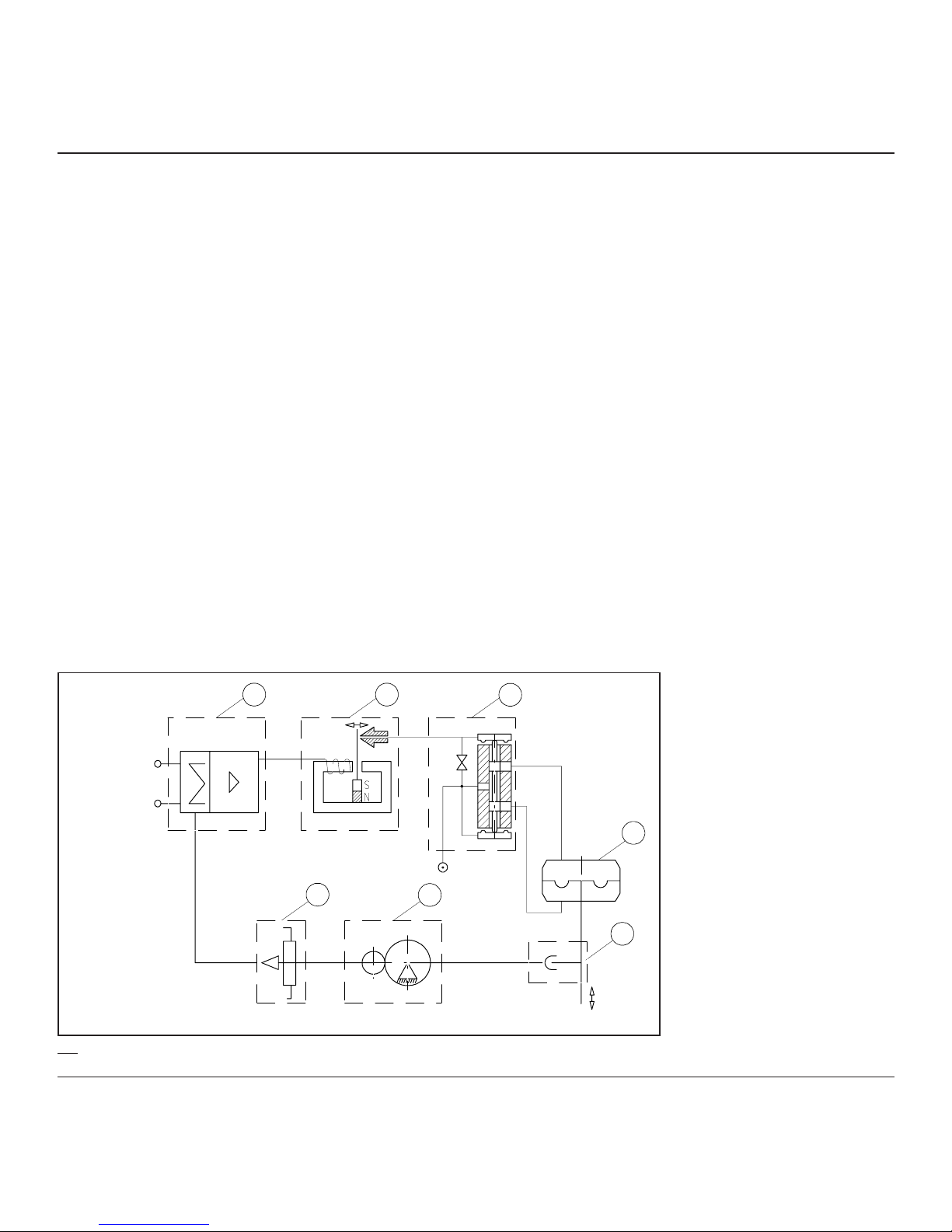
1.2 Operating Principles
The positioner provides the means for a pneumatic actuator to
be accurately positioned to any point between full open and full
closed position. The actuator’s movement is controlled in
proportion to a 4-20 mA incoming signal.
The actuator’s movement is monitored by the integral feedback
potentiometer (7), the signal from this and the incoming signal
are fed to the comparative electronics on the main circuit board
(1).
Providing these two signals are equal the resulting signal sent
to the I/P converter (2) is “Neutral” and the spool of the pilot
valve (3) is held in the mid or b loc k ed position.
In this state the actuator remains locked in the last set position,
that is at it’s “Set point”.
If, either the input mA. signal or the valve position changes then
the difference is sensed and the signal to the I/P is either
increased or decreased. This causes a corresponding movement of the pilot spool (3) which in turn starts the actuator’s
movement (4) towards the ne w “Set point”. On reaching this the
two signals are again equal and movement stops at this ne w
“Set point”.
For single acting (spring return) actuators only a single air line
is used, the other port at the spool valve (3) is plugged off .
1.0 Introduction / Einführung / Introductie
123
4
5
67
4-20 mA
Signal input
4-20 mA Signal input =
4-20 mA Eingangssignal =
4-20 mA Stuursignaal
1.1

7DOC,F20,EDN Rev.: -
1.0 Introduction / Einführung / Introductie
1.2 Arbeitsweise
Der Stellungsregler bietet die Möglichkeit, ein pneumatisches Stellglied in jeder beliebigen Stellung zwischen völlig auf und völlig geschlossen zu positionieren. Die Bewegung des Stellgliedes wird proportional zu einem Eingangssignal von 4-20 mA geregelt.
Die Stellbewegung des Antriebes wird von einem Rückführpotentiometer (7) erfaßt und in der Elektronikbaugruppe (1) mit
dem Eingangssignal verglichen.
Liegt Soll-Istwert Gleichheit vor, verbleibt der Stellantrieb in der jeweiligen Position.
Ändert sich das Stellsignal oder die Antriebsposition, wird die Abweichung erfaßt. Die Soll-Istwert Differenz wird elektronisch verstärkt und ändert das Magnetfeld der Festspule (2). Damit ändert
sich der Abstand zwischen Düse und Prallplatte. Die Kaskadendruckänderung verstellt das Verstärker-Ventil (3) am Ausgang. Der
Antrieb (4) bewegt sich in Richtung neuer Sollwert und stoppt bei
Erreichen der neuen Sollposition.
Bei einfachwirkenden Antrieben wird nur der eine Ausgang genutzt.
Der andere Ausgang wird verschlossen.
1.2 Werkingsprincipes
Door de montage van klepstandsteller F20 kan een pneumatische aandrijving nauwkeurig in elke stand tussen volledig geopend en volledig gesloten worden gezet. De beweging van de
aandrijving wordt ev enredig aan een 4-20 mA ingangssignaal
geregeld.
De beweging van de aandrijving wordt be waakt door de integrale terugkoppelpotentiometer (7). Het door deze
potentiometer afgegeven signaal en het ingangssignaal w orden
aan de vergelijkingselektronica op de hoofdprintplaat (1) toegevoerd.
Alleen wanneer deze twee signalen gelijk zijn, zal het aan de I/
P-omzetter (2) afgegev en resulterende signaal “neutraal” zijn,
waarbij de plunjer van de stuurklep (3) in de centrale of geb lokkeerde stand wordt gehouden.
In deze stand blijft de aandrijving in de laatst ingestelde positie,
te weten het instelpunt, vergrendeld.
Indien het mA-ingangssignaal of de klepstand verandert, wordt
het verschil gedetecteerd, waardoor het signaal naar de I/P
verhoogd dan wel v erlaagd wordt. Dit resulteert in een corresponderende beweging van de stuurklepplunjer (3) die w ederom
de beweging van de aandrijving (4) naar het nieuwe instelpunt
in gang zet. Zodr a dit punt is bereikt, zijn de beide signalen
weer gelijk en komt de beweging bij dit nieuwe instelpunt tot
stilstand.
Bij enkelwerkende (veerbelaste) aandrijvingen wordt slechts
een enkele luchtleiding gebruikt; de andere poort bij de
plunjerklep (3) wordt afgestopt.
8 DOC,F20,EDN Rev.: -
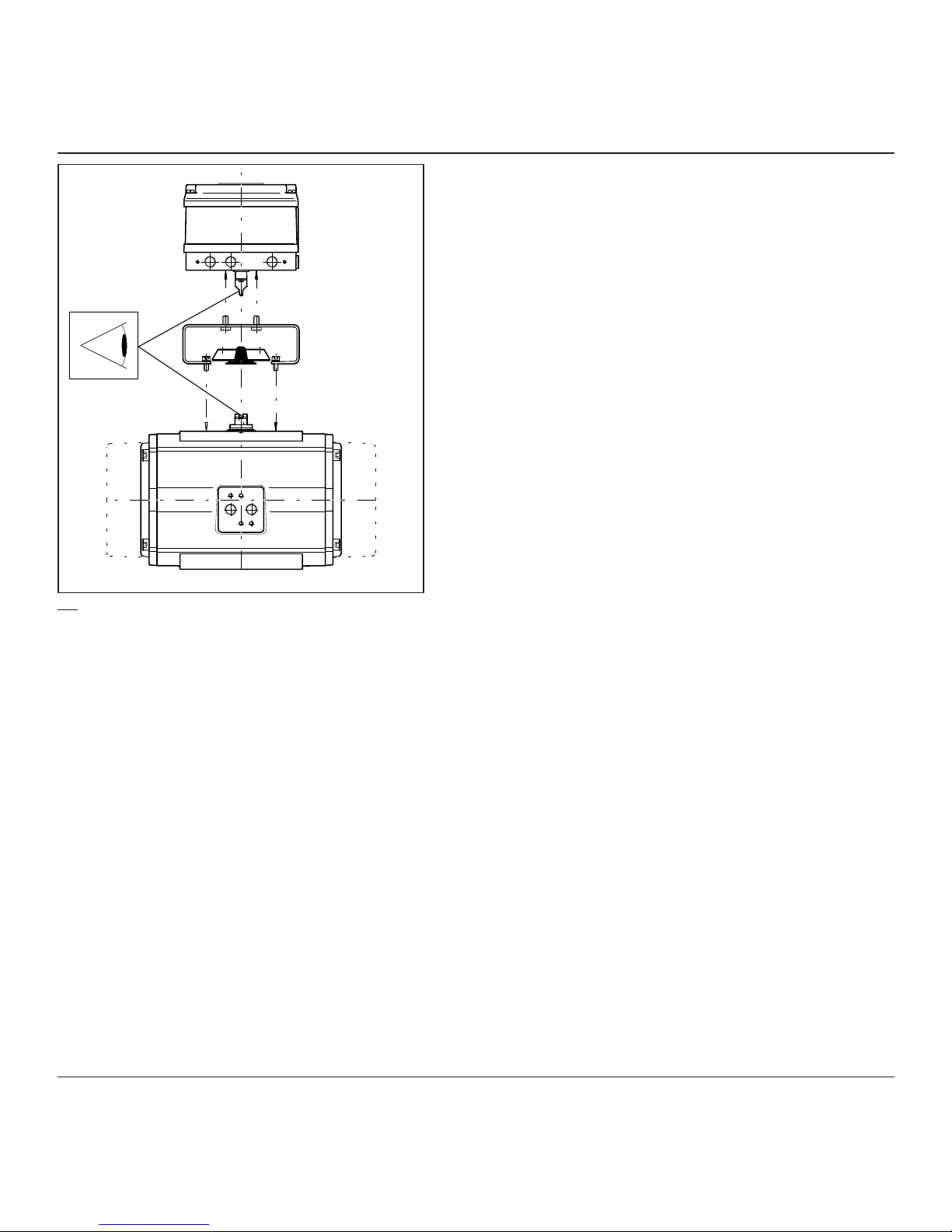
2.1 Mechanical Installation - Rotary
Actuators
The positioner is mounted on to the top surface of the pneumatic actuator using an appropriate mounting kit.
The positioner’s mounting configur ation is to the VDE/VDI 3845
standard, if the actuator is to the same standard, a standard
NAMUR mounting kit can be used, otherwise a special
mounting kit will have to be obtained.
Assuming the installation will use the standard NAMUR
mounting kit, proceed as follows:
1. Fix the bracket to the top surface of the actuator using the 4
screws provided.
2. Locate the positioner in place on top of the bracket, making
sure that the 4 mm. tongue locates properly into it’s slot in
the actuator spindle.
3. Fix the positioner to the bracket using the 4 screws pro-
vided.
2.0
2.0 Installation - Rotar y Actuators / Einbau Drehantriebe / Montage op roterende
aandrijvingen

9DOC,F20,EDN Rev.: -
2.0 Installation - Rotar y Actuators / Einbau Drehantriebe / Montage op roterende
aandrijvingen
2.1 Mechanischer Einbau - Drehantriebe
Der Stellungsregler wird oben auf dem pneumatischen Stellglied
montiert unter Anwendung eines entsprechenden Montagesatzes.
Die Montagekonfiguration des Stellungsreglers entspricht der Norm
VDE/VDI 3845. Wenn das Stellglied der gleichen Norm entspr icht,
kann ein Standard- NAMUR -Montagesatz verwendet werden. Sonst
sollte ein Sondermontagesatz bestellt werden.
Wenn der Standard-NAMUR-Montagesatz zum Einbau verwendet
wird, ist wie folgt vorzugehen:
1. Die Halterung mit den 4 mitgelieferten Schrauben auf der Ober-
seite des Stellglieds befestigen.
2. Den Stellungsregler oben auf die Halterung anordnen und kon-
trollieren, daß die federnde Kupplung richtig in die entsprechende Aussparung in der Spindel des Stellglieds eingreift.
3. Den Stellungsregler mit den 4 mitgelieferten Schrauben an der
Halterung befestigen.
2.1 Montage op roterende aandrijvingen
De klepstandsteller wordt met behulp van een daarvoor geschikte montagekit bovenop de pneumatische aandrijving gemonteerd.
De wijze van montage van de klepstandsteller is conf orm de
norm VDE/VDI 3845. Indien de aandrijving aan dezelfde norm
voldoet, kan een standaard NAMUR-montagekit worden gebruikt. Als dit niet het ge v al is , dient u een speciale montagekit
te bestellen.
Ervan uitgaande dat bij de montage gebruik wordt gemaakt
van de standaard NAMUR-montagekit, dient als volgt te werk
worden gegaan:
1. Bevestig de beugel met de 4 meegelev erde schroeven bovenop de aandrijving.
2. Plaats de klepstandsteller bovenop de beugel en zorg ervoor dat de 4 mm lange lip goed in de corresponderende
groef in de spil van de aandrijving v alt en dat de
centreerschroef in de juiste stand staat.
3. Monteer de klepstandsteller met de 4 meegeleverde schroeven op de beugel.
10 DOC,F20,EDN Rev.: -
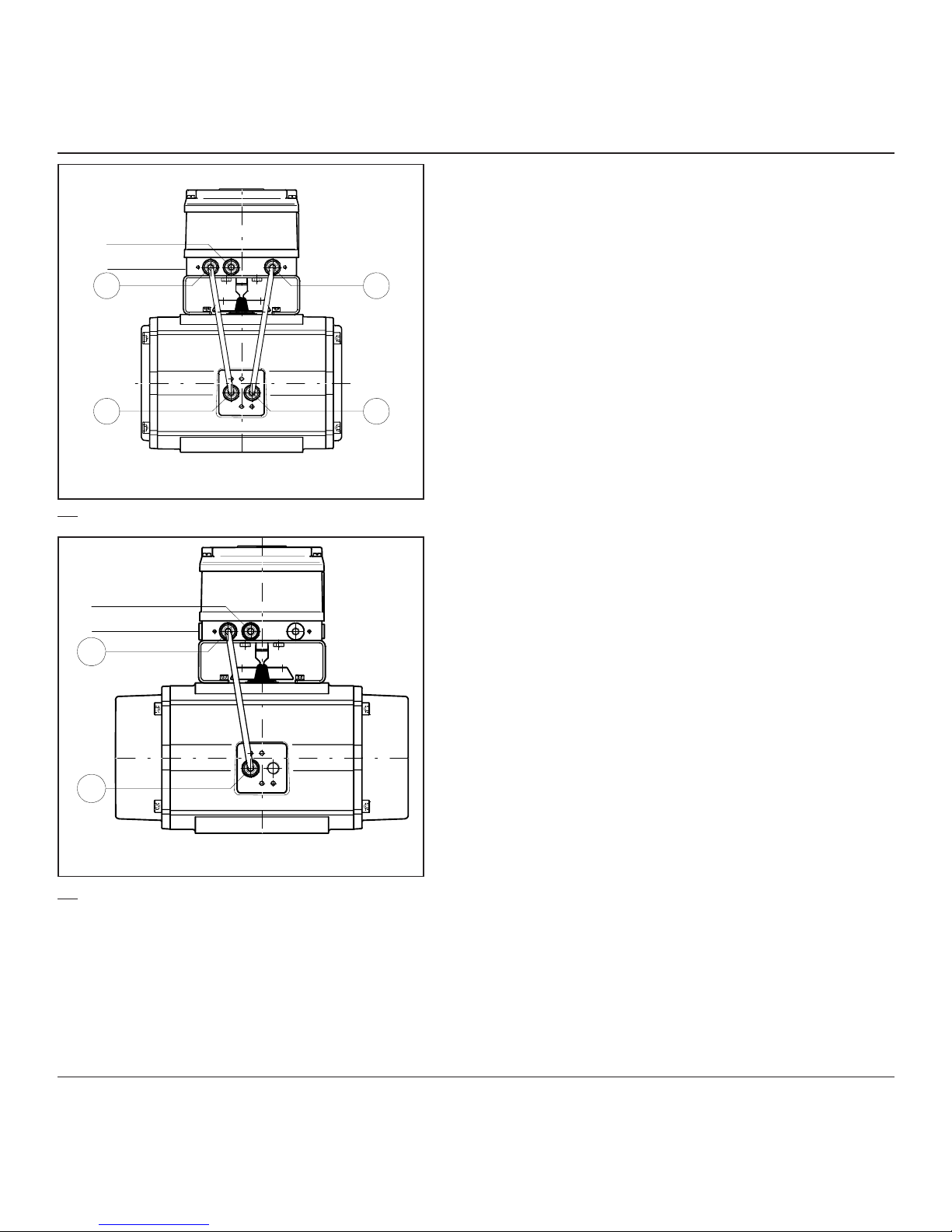
2.2 Pneumatic Connections
Assuming a standard (direct acting) installation with an
increasing signal to open the valve in a CCW (counter cloc kwise) direction.
Before connecting any air supply make sure that the air
available is c lean dry instrument air filtered to at least 25
microns.
2.2.1 Double acting
1. Connect an appropriate piece of air tubing between the port
1. on the positioner to the “A” port on the actuator. (The “A”
port is the one that when air is applied to it, rotates the
actuator in a counter clockwise direction).
2. Connect an appropriate piece of air tubing between the port
2. on the positioner to the “B” port on the actuator. (The “B”
port is the one that when air is applied to it, rotates the
actuator in a clockwise direction).
3. If the positioner is required to meet enclosure rating IP54, be
sure that the sintered filter is in place at the “Exhaust” port.
4. Connect an air supply to the positioner port marked
“Supply”.
Note:
The same procedure is applicable to connect a double
acting actuator with reverse action. Onl y select "Re ver se
Action", see page 20.
For electrical installation, see page 16.
2.2.2 Single acting
1. Connect an appropriate piece of air tubing between the port
1. on the positioner to the “A” port on the actuator. (The “A”
port is the one that, when air is applied to it, rotates the
actuator in a counter clockwise direction).
2. Connect an air supply to the positioner port marked
“Supply”.
3. If the positioner is required to meet enclosure rating IP54, be
sure that the sintered filter is in place at the “Exhaust” port.
Note:
The same procedure is applicable to connect a single
acting actuator with reverse action, only select "Reverse
Action", see page 22.
For electrical installation, see page 16.
2.0 Installation - Rotar y Actuators / Einbau Drehantriebe / Montage op roterende
aandrijvingen
Double acting
Supply
Exhaust
Supply
Exhaust
12
AB
Double acting
2.1
2.2
Supply
Exhaust
1
A
= Doppelt Wirkend
= Luftversorgung
= Entlüftung
= Dubbel werkend
= Luchtaansluiting
= Ontluchting
Single acting
 Loading...