

Page 1
Installation Instructions
TBB-K
Towel Rails
TBB-8K | TBB-12K | TBC-8K | TBC-12K
Please read these instructions carefully before
installing or using this appliance for the first time.
Page 2
1. WARNING
• The warranty of the towel rail will not cover any
damage caused by the non observance of any of
these instructions. Please read these instructions
before installing or using this appliance for the first
time. This guide must be kept and given to any
new user.
• This appliance can be used by children aged from
8 years and above and persons with reduced
physical, sensory or mental capabilities or lack of
experience and knowledge if they have been given
supervision or instruction concerning the use of the
appliance in a safe way and understand the hazards
involved. Children must not play with the appliance.
Cleaning and user maintenance must not be made
by children without supervision.
• Children aged from 3 years and less than 8 years
shall only switch on/off the appliance provided
that it has been placed or installed in its intended
normal operating position and they have been
given supervision or instruction concerning use
of the appliance in a safe way and understand the
hazards involved. Children aged from 3 years and
less than 8 years shall not plug in, regulate and clean
the appliance or perform user maintenance.
• Children of less than 3 years should be kept away
unless continuously supervised.
• Please, check that the voltage in the rating label fits
the power supply.
• The surfaces of the towel rail can be hot and caution
is advised when small children are near the
appliance. WARNING: In order to avoid a hazard for
very young children, this appliance should be
installed so that the lowest heated rail is at least
600 mm above the ground.
• Before carrying out any work inside the appliance,
the towel rail must be disconnected from the
electricity supply.
• The use of electric towel rails is forbidden in any
area where there is a presence of gases, explosives
or inflammable objects.
• The towel rail should not be installed exactly under
an electric outlet.
• The appliance must be installed in such a way that
it is impossible for anyone using a bath or shower,
to touch the controls.
• The towel rail is fitted with a flexible cable size
3 x 1.00 mm² for electrical connection. It may be used
to connect the heater to the fixed wiring of the
premised through a suitable connection box
positioned adjacent to the heater.
• The supply circuit to the towel rail must incorporate
a double pole isolating switch having a contact
separation of at least 3 mm.
• The installation must be carried out in accordance
with the current electrical regulations. Should the
towel rail be moved and reinstalled it is essential that
the work is carried out by a fully qualified technician.
• The supply lead must not contact the surface of the
towel rail.
• If the supply lead of the towel rail is damaged it must
be replaced by service personnel authorized by the
manufacturer, since special tools are needed.
• This towel rail is filled with a precise quantity of
thermal fluid. Repairs requiring opening of the fluid
container are only to be made by the manufacturer
or his service agent who should be contacted if there
is a fluid leakage.
• Regulations concerning the disposal of fluid when
scrapping the appliance have to be followed.
• The presence of air particles of smoke, dust and
other pollutants could, in time, discolour the walls
and surfaces around the towel rail.
• All the models incorporate a safety device. This will
disconnect the towel rail if for some reason it fails.
If the safety device activates the towel rail will need
to be repaired by service personnel authorized by
the manufacturer.
2. INSTRUCTIONS
FOR INSTALLATION
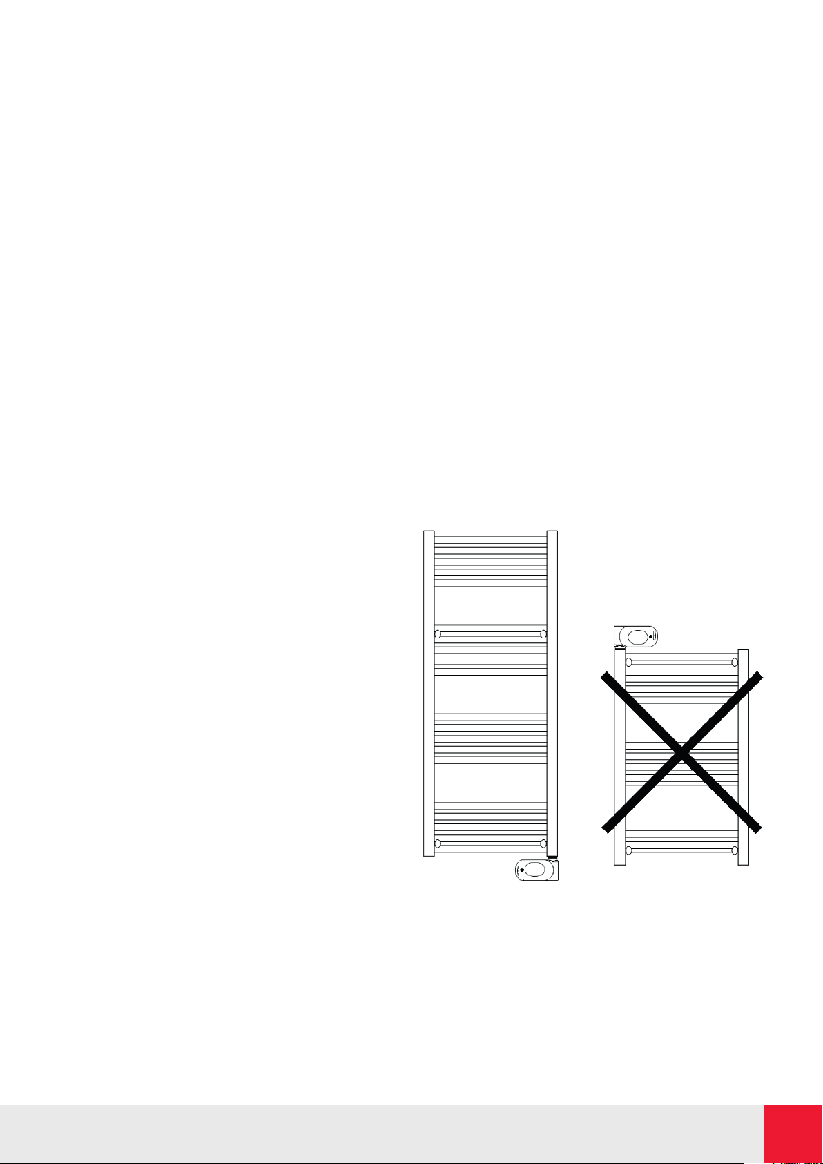
The towel rail is designed to only work in a vertical
position and fixed to the wall, never to the ceiling.
The fixation to the wall is carried out by means of the
supports given with the appliance, according to the
following outline.
A clear distance of 5 cm must be allowed around
the towel rail.
Cable exit always on the lower right side.
Elnur powered by Gabarrón | ECOMBI SSH | User Guide 2
Page 3
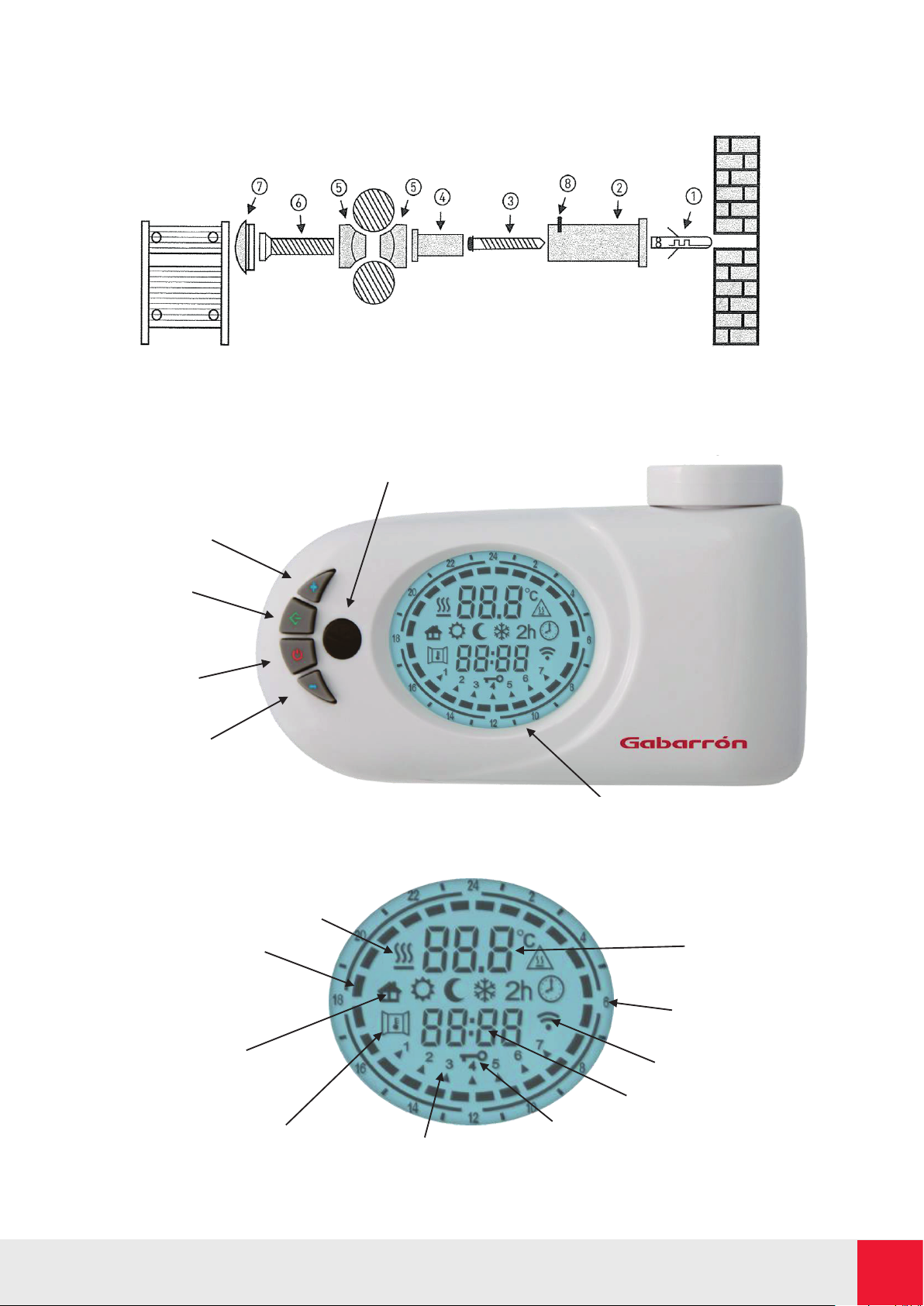
Connect the wires to a fix wall socket or to an appropriate plug WITHOUT EARTH. Connect the black wire
IR Receiver: Allows full remote control of the device trough the
Connect the wires to a fix wall socket or to an appropriate plug WITHOUT EARTH. Connect the black wire
to the signal wire when available. Do not connect this wire to any EARTH lead.
The towel rail supports should be placed in sequence as indicated below:
3.- APPLICATION OF USE
Indicator of active
Button [-]
Button [On / Off]
Button [Prog]
Button [+]
Backlit Display: Displays all device
Comfort / Eco bar
Operating
Open Window Detection
Day of the week
Key-lock icon
Clock
Configured temperature
to the signal wire when available. Do not connect this wire to any EARTH lead.
The towel rail supports should be placed in sequence as indicated below:
3. APPLICATION OF USE
heating element
(Chrono mode)
mode icons
IR Receiver: Allows full remote control of the device
through the dedicated remote control.
dedicated remote control.
related information.
24h indicator
IR receiver indicator
Elnur powered by Gabarrón | ECOMBI SSH | User Guide 3
Page 4
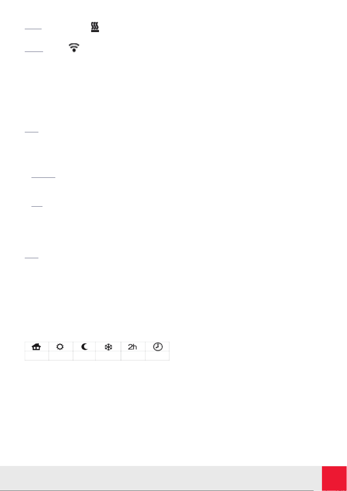
Note 1: When the symbol is on, the heating
element is active.
Note 2: This icon indicates that is being received
signal from remote control. (optional).
POWER ON / STAND-BY
Press the [On/Stand-by] key to turn on the device or to
enter the “Stand-by” mode.
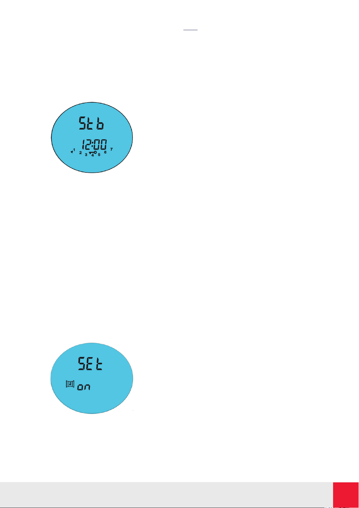
When activated, the bottom part of the display shows
the current time, while the configured operative mode
and the temperature are shown in the upper part, when
in “Stand-by” mode current time, day of the week and
the message “ Stb” are displayed.
Note: When the device goes into “Stand-by” mode it
beeps twice for 0.5s. When the device is activated it
beeps once for 1s.
COMFORT & ECO TEMPERATURES
Two different levels of temperature can be set:
- Comfort: Temperature level used for Chrono, Pilot
Wire and Comfort modes. It is recommended for the
periods of time when the user is at home and the
maximum comfort is required.
- Eco: Temperature level used for Chrono and Eco
modes. It is recommended for nights and small away
periods of time.
Set the mode of the temperature level to modify
(Comfort or Eco) using the button [Prog] and modify its
value for each level. The desired temperature can be set
pressing the [+] and [-] buttons. (From 7ºC to 32ºC).
Note: The temperature of “Eco” mode must be below to
the “Comfort” mode temperature. For this reason, the
“Eco” mode temperature can be set to a value between
7°C and the configured “Comfort” mode temperature
and the “Comfort” mode temperature can be set to a
value between the configured “Eco” mode temperature
and 32ºC.
OPERATING MODES
Press the [Prog] button to select the desired operative
mode. An icon on the display indicates the selected
operating mode, according to the following table:
Pilot Wire Comfort Eco Frost Prot. Timer-2h Chrono
COMFORT MODE
The “Comfort” mode maintains the room temperature to
the selected value. To set this operative mode:
- Press the [Prog] button until the display shows the
“Comfort” icon.
- Set the desired temperature trough [+] and [-] buttons
and wait until the displayed temperature stops
blinking.
ECO MODE
The “Eco” mode sets a value of temperature below the
“Comfort” temperature value. It is suggested to set this
operating mode during the night or when the room is
not occupied for 2 or more hours.
- Press the [Prog] button until the display shows the
“Eco” icon.
- Set the desired temperature using the [+] and [-]
buttons and wait until the displayed temperature
stops blinking.
FROST PROTECTION MODE
In “Frost Protection” mode, the temperature is fixed
to 7°C. The device activates the heating element when
the room temperature falls below 7°C. It is suggested
to set this operating mode when the room is not
occupied for several days.
- Press the [Prog] button until the display shows the
“Frost Protection” icon.
2H-TIMER MODE
The “Timer 2h” mode can be used to quickly warm up
the room or to speed up towel drying.
- Press the [Prog] button until the display shows the
“2h-Timer” icon.
The device is activated at the maximum power for 2
hours, up to a maximum room temperature of 32°C.
The “Timer-2h” mode is automatically deactivated
after a period of 2 hours and the device returns to the
operative mode previously set. The user can switch to
another operative mode at any time by simply pressing
the [PROG] button.
PILOT WIRE MODE
(Only for product versions equipped with “Pilot Wire”)
In “Pilot Wire” mode, the device is managed by a central
control system that sets the operating mode for all
the connected devices. The device operates with the
most advanced “Pilot Wire” system with six commands,
which allows the following functions:
1 Standby: Power off the heating element, the device
remains active.
2 Comfort: Maintains the “Comfort” temperature set
by the user.
3 Eco: Maintains the room temperature 3,5°C below
the “Comfort” temperature.
4 Frost Protection: Maintains the room temperature
at 7°C.
5 Eco-1: Maintains the room temperature 1°C below
the “Comfort” temperature.
6 Eco-2: Maintains the room temperature 2°C below
the “Comfort” temperature.
The user can set the desired temperature on the device.
- Press the [Prog] button until the display shows the
“Pilot Wire” icon.
- Set the desired temperature trough [+] and [-] buttons
and wait until the displayed temperature stops
blinking.
Elnur powered by Gabarrón | ECOMBI SSH | User Guide 4
Page 5
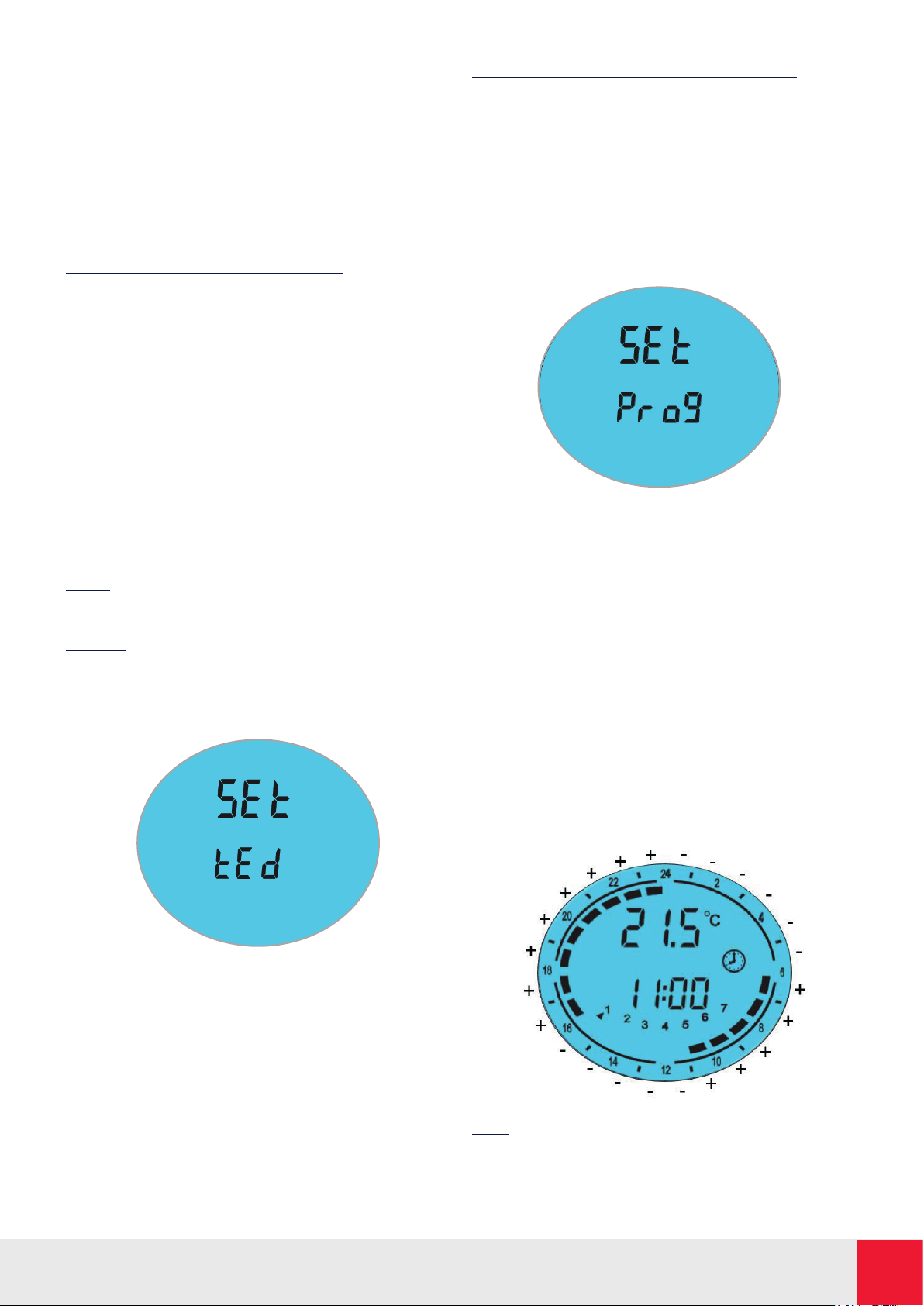
CHRONO MODE
This operating mode allows the user to configure
different temperature values for each hour of each
day of the week. The “Comfort” / “Eco” temperatures
and the related time intervals can be programmed.
To activate this function:
- Press the [Prog] button until the display shows
the “Chrono” icon.
PROGRAMMING THE “CHRONO” MODE
a) Setting the day of the week and time
- Enter into “Stand-by” mode and press the [-] button
at least 3 seconds.
- On the upper part of the display the message “Set”
will be displayed.
- To set the day and time press the [+] button until
the bottom part of the display the message “Ted”
is displayed.
- Press the [Prog] button to enter the editing mode.
- The blinking arrow indicates the currently selected
day, pressing the [+] /[-] buttons the desired day can
then be set. Press again the [Prog] button to confirm
the selected day.
- The procedure for entering the time starts and the
display shows the current time.
Hours: Use the [+] and [-] buttons to set the correct
hour and confirm the selected value pressing the
[Prog] button.
Minutes: Same procedure as for the hours. Confirm
the selected value by pressing the [Prog] button.
- At the end of the procedure, the thermostat returns
into “Stand-by” mode.
b) Setting the program for the “Chrono” mode.
- Enter into “Stand-by” mode and press the [-] button
at least 3 seconds.
- On the upper part of the display the message
“Set” will be displayed.
- To set the day and time press the [+] button until
the bottom part of the display the message “Prog”
is displayed.
- Press the [Prog] button to enter the editing mode.
- The procedure starts with day 1, and the desired
sequence can be configured with the [+] and [-]
buttons. For each hour of the day, it is possible to
assign either the “Comfort” or “Eco” temperature.
o Press the [+] button to set the “Comfort”
temperature level for the current hour.
(full bar indication displayed).
o Press the [-] button to set the “Eco”
temperature level for the current hour.
(empty bar indication displayed).
- Press [Prog] to confirm the entered configuration
for day 1, and repeat the same procedure for the
remaining 6 days of the week.
- Press [Prog] button again when having finished
the programme of the 7 days. The display returns
into “Stand-by” mode.
Note: In case of loss of power supply, the settings
of the “Chrono” mode remain stored in memory
for a few minutes.
Elnur powered by Gabarrón | ECOMBI SSH | User Guide 5
Page 6
KEY LOCK
It is possible to lock the buttons of the device to avoid
inadvertent modifications of the settings.
Press the [Prog] button for 3 seconds to lock all the
buttons except the [On/Off] button. The key-lock icon
is activated on the display.
To unlock the buttons, press again the [Prog] button
for 3 seconds.
The key-lock icon disappears on the display.
OPEN WINDOW DETECTION FUNCTION
The “Open Window Detection” function enables
detecting of an open window by sensing a sudden
decrease of the temperature in the room. In such a
case, the device deactivates the heating element for a
maximum of 30 minutes or until an increase of the room
temperature reveals that the window has been closed.
To activate this function:
- Enter into “Stand-by” mode.
- Press the [+] button for 3 seconds. The Open Window
Detection icon is shown blinking in the display and
its status.
- Press the [+] button to activate / deactivate the function.
- Press the [Prog] button to commit and return into
“Stand-by” mode.
When this function is enabled, the “Open Window” icon
on the display is lit and when the device detects that
the window is opened, the “Open Window”
icon starts blinking. When the function is disabled the
“Open Window” icon is not shown on the display.
Note: The device could fail in detecting an opened
window e.g. if the thermostat is located on an isolated
area of the room and far from air currents or if the
thermostat is placed close to an external heating source.
REMOTE CONTROL (OPTIONAL)
TBB-K towel rail is equipped with an IR receiver and
therefore it can be remotely controlled through the
optional remote-control device. All the functions
previously described are available on the remote control.
4. MAINTENANCE
The towel rail doesn’t require any type of special
maintenance. Clean it with a cloth, only when the unit is
disconnected and cold. Do not use solvents or abrasive
products when cleaning.
The towel rail is filled with a precise quantity of special
fluid. Any repairs that may require the opening of the
towel rail must only be carried out by the manufacturer.
The towel rail has been manufactured to assured quality
and according to processes to protect the environment.
Once at the end of the useful life of the appliance, take
it to a clean point so that its materials can be recycled
appropriately.
Elnur powered by Gabarrón | ECOMBI SSH | User Guide 6
Page 7
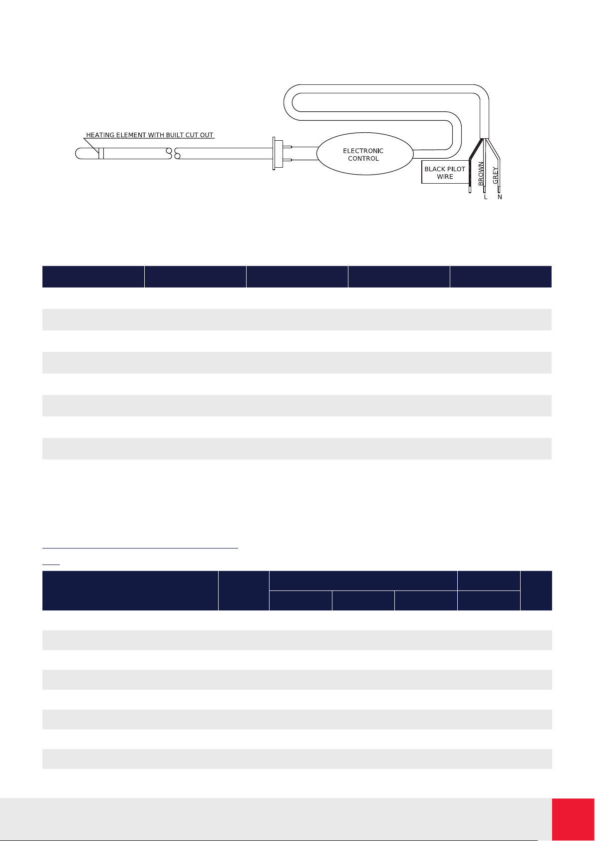
5. WIRING DIAGRAM
5.- WIRING DIAGRAM
6. TECHNICAL SPECIFICATIONS
Model TBB-8K TBB-12K TBC-8K TBC-12K
Power (W) 300 600 300 500
Voltage (V) 220–240V~ 220–240V~ 220–240V~ 220–240V~
Length (cm) 50 50 50 50
Width (cm) 8 8 8 8
Height (cm) 87 128 87 128
Weight (kg) 10 14 10 14
Isolation Class II Class II Class II Class II
IP Protection IP44 IP44 IP44 IP44
Frequency (Hz) 50 50 50 50
7. PRODUCT FICHE
MODEL(S): GABARRON TBB-8K, TBB-12K
ErP
Value
Item Symbol TBB-8K TBB-12K TBC-8K TBC-12K Unit
Heat Output
Nominal heat output
Minimum heat output
Maximum continuous heat output
Auxiliary electricity consumption
At nominal heat output
At minimum heat output
In standby mode
Elnur powered by Gabarrón | ECOMBI SSH | User Guide 7
P nom
P min
P max, c
el max
el min
el sb
0.3 0.6 0.3 0.5 kW
N.A. N.A. N.A. N.A. kW
0.3 0.6 0.3 0.5 kW
0.000 0.000 0.000 0.000 kW
0.000 0.000 0.000 0.000 kW
<0.0005 <0.0005 <0.0005 <0.0005 kW
Page 8
El símbolo en el producto o en su embalaje indica que este
producto no se puede tratar como desperdicios normales del
hogar. Este producto se debe entregar al punto de recolección
de equipos eléctricos y electrónicos para reciclaje. Al asegurarse
de que este producto se deseche correctamente usted ayudará
a evitar posibles consecuencias negativas para el ambiente
y la salud pública, lo cual podría ocurrir si este producto no
se manipula de forma adecuada. Para obtener información
más detallada sobre el reciclaje de este producto, póngase en
contacto con la administración de su ciudad, con su servicio de
desechos del hogar o con la tienda donde compró el producto.
Estas disposiciones solamente son válidas en los países
miembros de la UE.
Supplier:
ELNUR UK Ltd.
Unit 1, Brown Street North
Leigh, Lancashire, WN7 1BU.
+44(0)1942 670119
[email protected]
Manufactured by:
ELNUR S.A.
Travesía de Villa Esther, 11 28110, Algete
Madrid Telephone: +34 916281440
15190020 R2 | EN
The symbol on the product or in its packaging indicates that this
product may not be treated as household waste. Instead it shall
be handed over to the applicable collection point for the recycling
of electrical and electronic equipment. By ensuring this product
is disposed of correctly, you will help prevent potential negative
consequences for the environment and human health, which
could otherwise be caused by inappropriate waste handling of
this product. For more detailed information about recycling of this
product, please contact your local council office, your household
waste disposal service or the shop where you purchased the
product. These instructions are only valid in the EU member states.
www.elnur.co.uk
© All rights reserved. As part of the continuous improvement
policy, ELNUR, S.A. reserves the right to alter or modify any
specifications without notice.
 Loading...