

Page 1
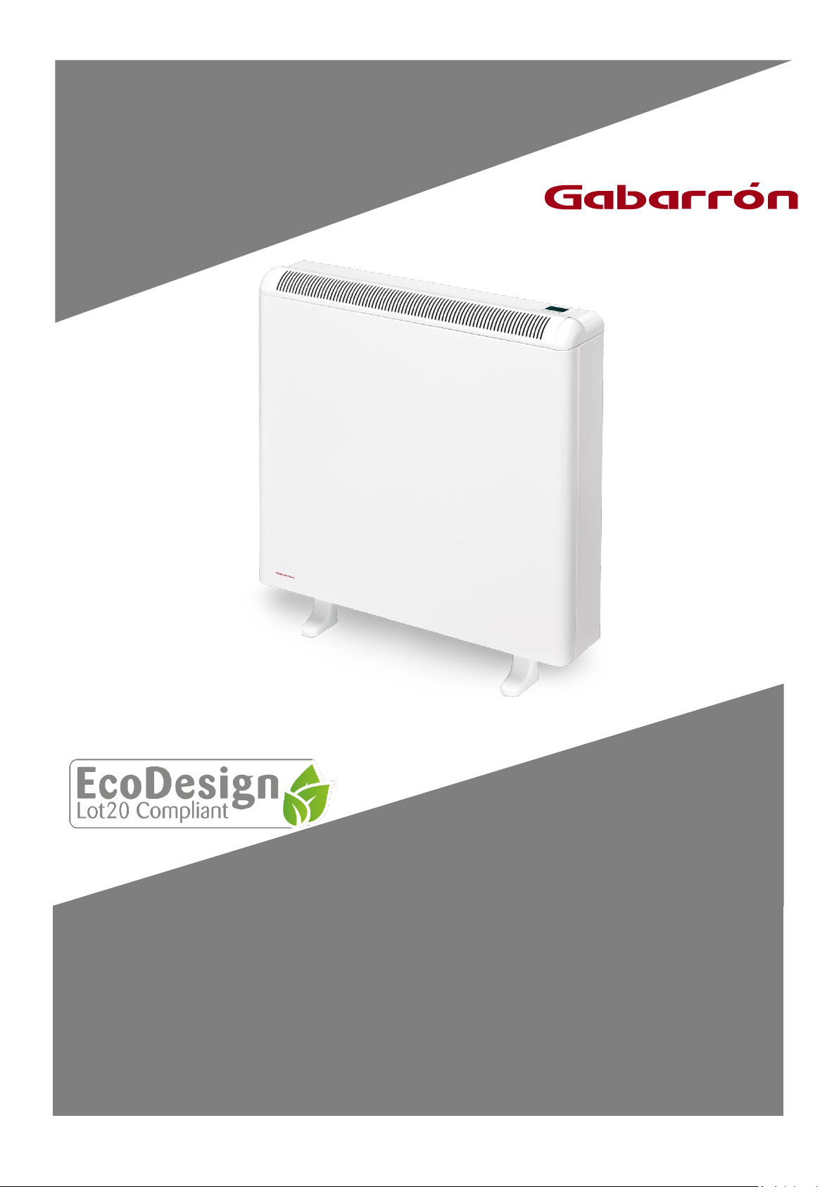
INSTALLATION INSTRUCTIONS AND USER GUIDE
ECOMBI SSH
SMART STORAGE HEATER
ECOSSH158
ECOSSH208
ECOSSH308
ECOSSH408
Please, read these instructions CAREFULLY before installing or using this appliance for the first time.
Page 2
1
1. –IMPORTANT INFORMATION
When using electrical appliances, basic precautions should always be followed to reduce the risk of fire, electric shock,
and injury to persons, including the following:
• WARNING: Please read all instructions before installing or using this heater for the first time.
• This heater is hot when in use. To avoid
burns, do not let bare skin touch hot
surfaces.
• Keep combustible materials, such as
furniture, pillows, bedding, papers, clothes,
etc. and curtains at least a foot (30cm) from
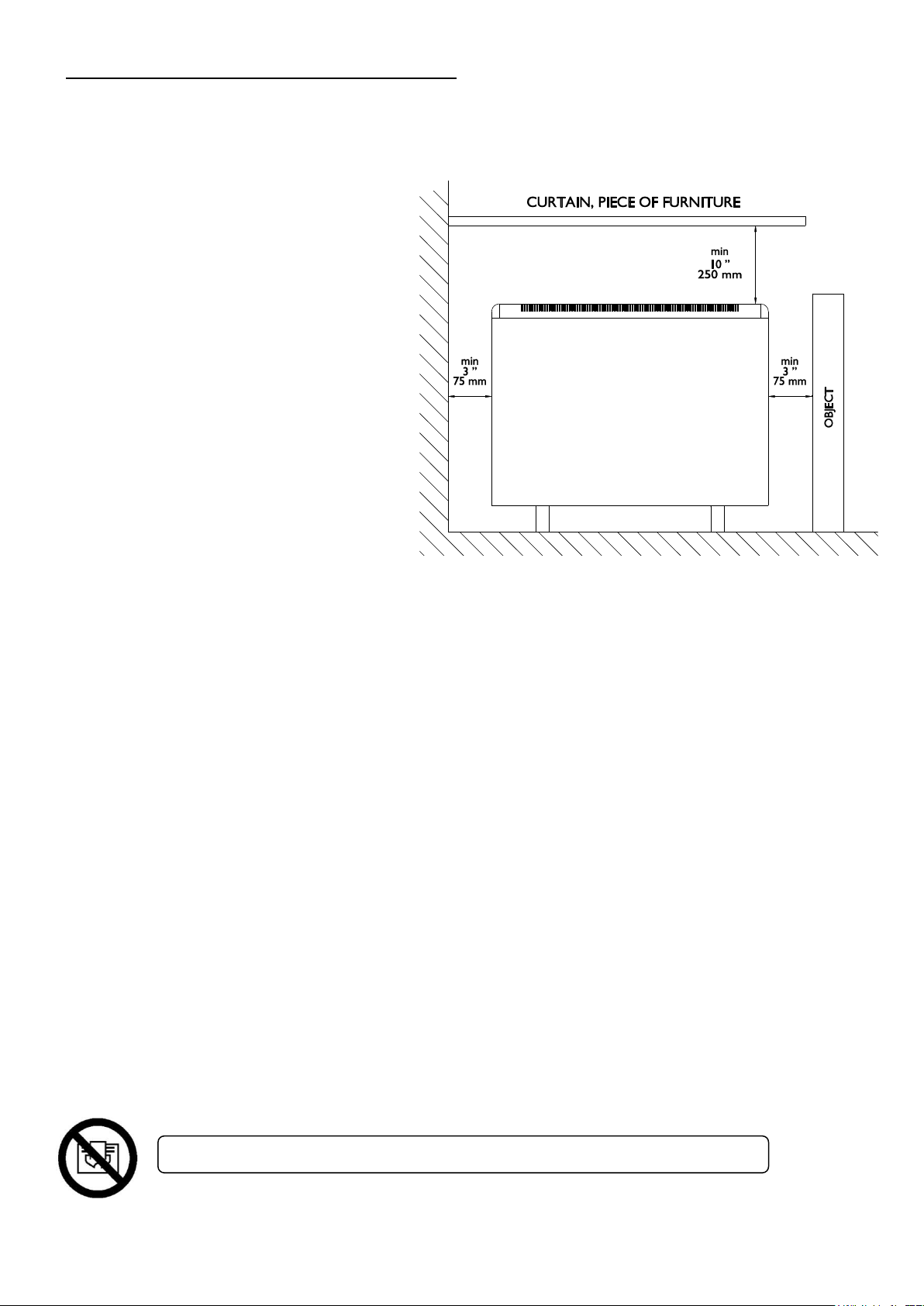
the front, sides and rear of the heater.
• It is essential that the indicated minimum
clearances are maintained.
• CAUTION — Some parts of this product
can become very hot and cause burns.
Particular attention must be given where
children and vulnerable people are present.
• Children should be supervised to ensure they do not play with the heater.
• Extreme caution is necessary when any heater is used by or near children or invalids and whenever the heater is left
operating unattended.
• This appliance can be used by children aged from 8 years and above and persons with reduced physical, sensory or
mental capabilities or lack of experience and knowledge if they have been given supervision or instruction concerning
the use of the appliance in a safe way and understand the hazards involved. Children must not play with the appliance.
Cleaning and user maintenance must not be made by children without supervision.
• Children aged from 3 years and less than 8 years shall only switch on/off the appliance provided that it has been placed
or installed in its intended normal operating position and they have been given supervision or instruction concerning
use of the appliance in a safe way and understand the hazards involved. Children aged from 3 years and less than 8 years
shall not plug in, regulate and clean the appliance or perform user maintenance.
• Children of less than 3 years should be kept away unless continuously supervised.
• Do not operate any heater after it malfunctions. Disconnect power at service panel and have heater inspected by a
reputable electrician before reusing.
• Do not use the heater outdoors.
• To disconnect heater, turn controls to off, and turn off power to heater circuit at main disconnect panel.
• Do not insert or allow foreign objects to enter any ventilation or exhaust opening as this may cause an electric shock
or fire, or damage the heater.
• Do not use this heater to dry clothes. To prevent a possible fire, do not block air intakes or exhaust in any manner.
• Air inlets and outlets provide proper operation of the appliance and prevent its overheating. DO NOT cover air inlet
and outlet grills.
• A heater has hot and arcing or sparking parts inside. Do not use in areas where gasoline, paint, or flammable vapors or
liquids are used or stored. The use of these heaters is forbidden in any area where there is a presence of gases,
explosives or inflammable objects.
• Use this heater only as described in this manual. Any other use not recommended by the manufacturer may cause fire,
electric shock, or injury to persons.
• SAVE THESE INSTRUCTIONS. This guide must be kept and given to any new user.
WARNING: In order to avoid overheating do not cover the heater.
Page 3
2
2. - INSTALLATION INSTRUCTIONS
The symbols used in the text are explained below:
WARNING This indication shows the possibility of causing death from electric shock.
WARNING This indication shows the possibility of causing death or serious injury.
CAUTION This indication shows the possibility of causing injury or damage to properties only.
Symbol for useful information.
IMPORTANT: Wiring procedures and connections shall be in accordance with the national and local codes having jurisdiction.
• The warranty of the heater will not cover any damage caused by non observance of any of these instructions.
• The installation must be carried out in accordance with the current local electrical regulations. Any installation or
reinstallation has to be carried out by an experienced technician.
• Neither the connecting cable nor any other object must come into contact with the hot unit.
• Please check that the voltage in the rating label fits the power supply.
• This appliance must be grounded.
• The appliance should not be installed just below an electrical socket.
• The appliance must be installed in such a way that it is impossible for anyone using a bath or shower, to touch the
controls.
• If during any installation the thermal insulation shows any sign of damage, it must be replaced.
• This heater should be switched off at the circuit breaker before any repair work is carried out. This should also be done
during times of the year when heat is not required.
• This appliance is only for permanent connection to a fix installation. The supply circuit to the heater must incorporate a
double pole isolating switch having a contact separation of at least 3 mm.
• The nominal charging period of this heater is indicated in the rating label.
• After installation a survey of the first charging cycle should be carried out to ensure that the main input thermostat
switches off. Ventilate the room during this first cycle.
• Never open a charged heater.
• To maintain stability, it is essential that the heater is placed on a level surface and care should be taken to avoid
irregular surfaces, such as may result from carpets or tiled surrounds partially protruding under the heater.
• The presence of air particles of smoke, dust and other pollutants could, in time, discolor the walls and surfaces around
the heater.
• Incorrect time settings, erroneous programming of the reduced rate time and too high temperature settings may result
in a high cost of your electricity bill.
In order to achieve a correct installation of this device, follow these steps:
1. - Choose the right location to install ECOMBI SSH. The minimum clearances must be respected from the appliance to any
combustible material such as furniture or curtains. To reduce the risk of fire, do not store or use gasoline or other
flammable vapors and liquids in the vicinity of the heater.
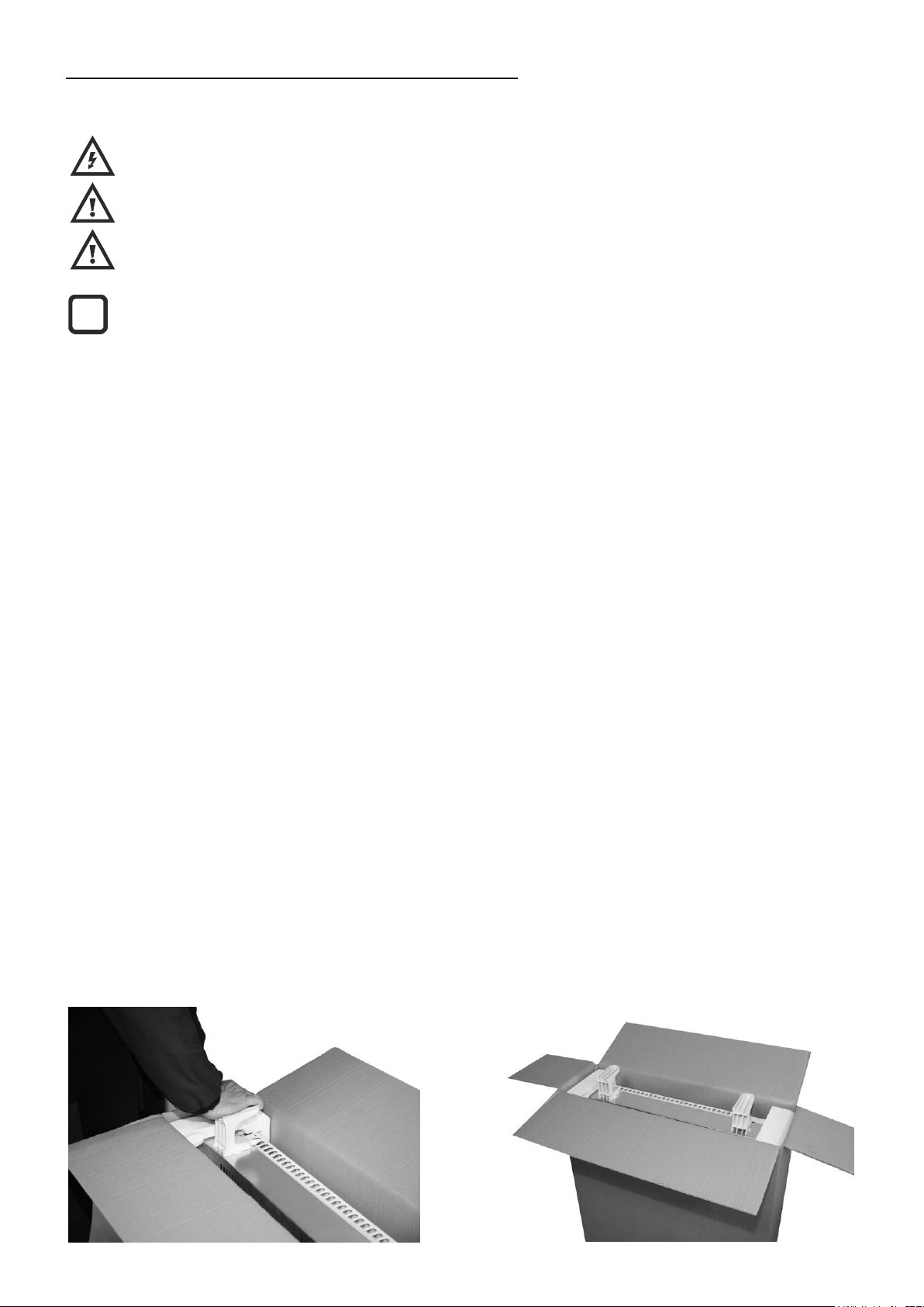
2. - Open the carton at the indicated side and install the supporting feet without removing the heater.
i
Page 4
3
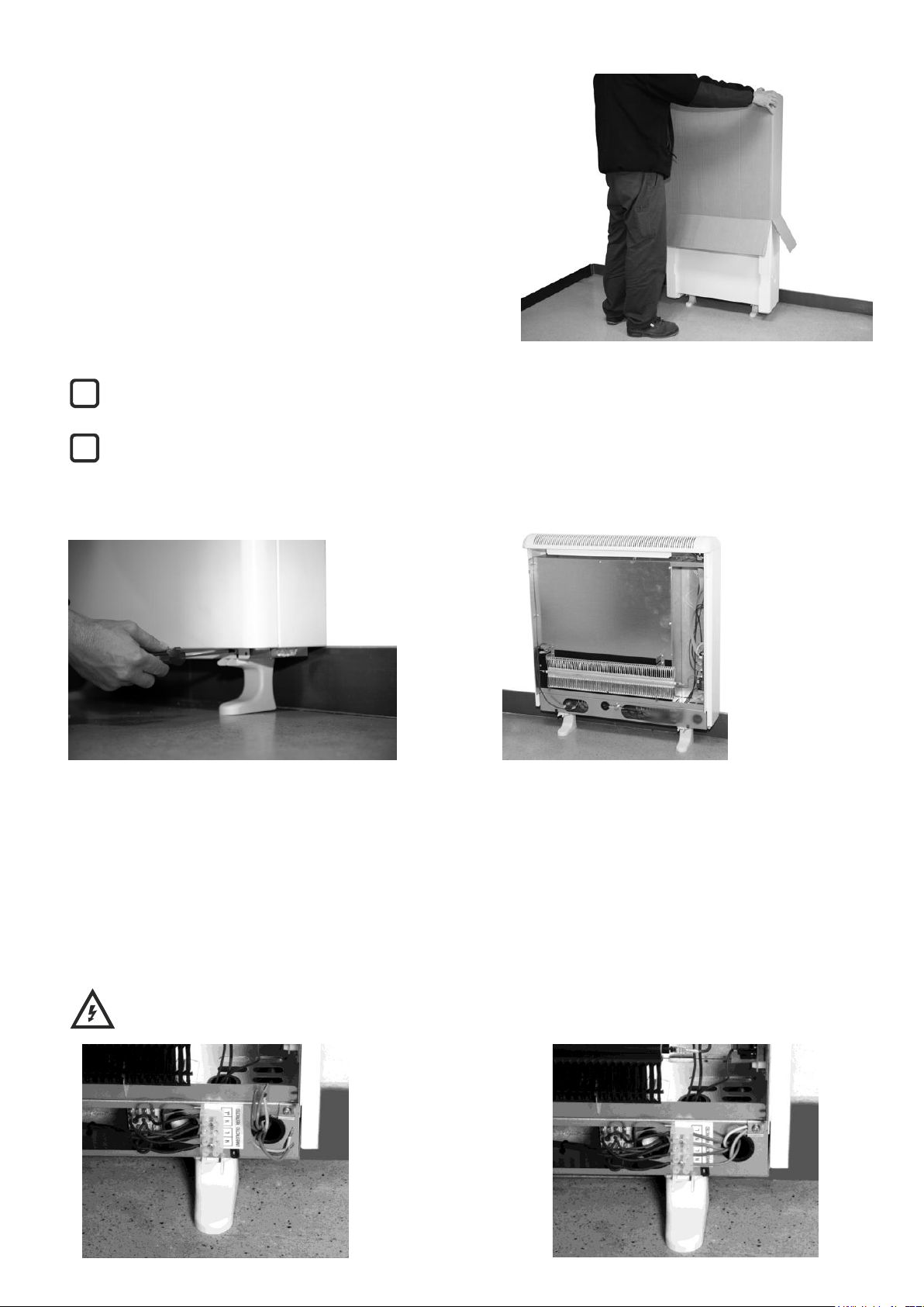
Turn the carton upside down to allow the heater to stand on its feet and remove the carton. Check that it is the correct model
and that it is in good conditions.
Check that all parts have been delivered and are intact.
- 1 Ecombi SSH heater casing.
- 1 bag containing 2 screws and 2 rawl plugs.
- 2 supporting feet.
- This guide.
- 1 superior fixing fitting.
- 2 lateral fixing fitting.
The casing and storage bricks are supplied separately. Check the supplied bricks packages correspond to the ones
indicated on the heater carton.
The heater operation is not affected if bricks with minor damage are used.
3. - Take off the front panel by removing the two screws located at the bottom. Fix the lateral fittings to the metal structure by
using the appropriate screws.
4. - Place ECOMBI SSH in your selected installation area. Use the heater fixing holes as a template and mark the wall through the
fixing holes with a pencil. Drill the required holes into the wall. Place the rawl plugs and screws into the holes before the
appliance installation but do not fasten them tightly.
5. Attach ECOMBI SSH to the rawl plugs with the crews. IT MUST NOT BE HUNG ON THE SCREWS; these are used only to
prevent the device from overturning and not to support it. If there is any doubt concerning the wall strength, consult the
corresponding construction specialist. The appliances are heavy; it is the installer responsibility the correct installation and wall
support of these devices to prevent them from overturning.
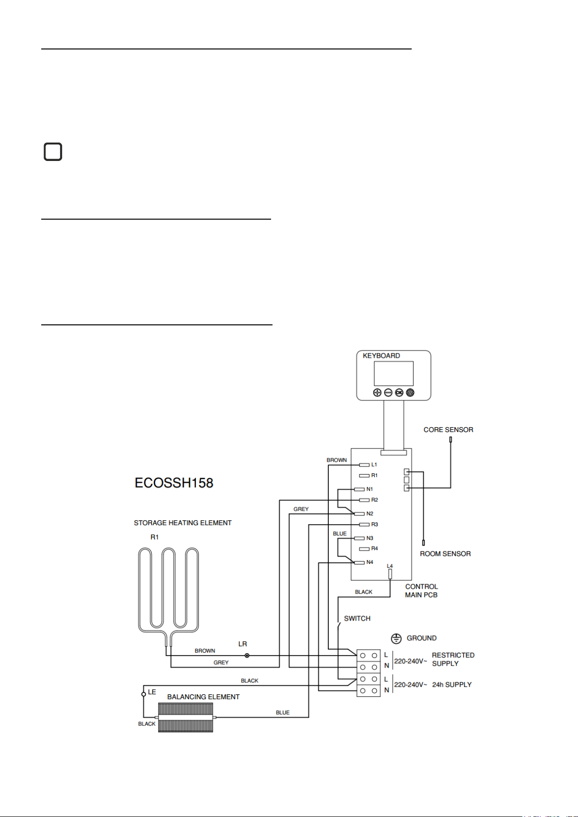
6. - Connect the heater using the wiring diagram included at the end of this manual. Tighten properly the connection block
screws. Do not leave any remaining wire inside the heater.
WARNING Touching live connections can cause serious personal injury.
i
i
Page 5
4
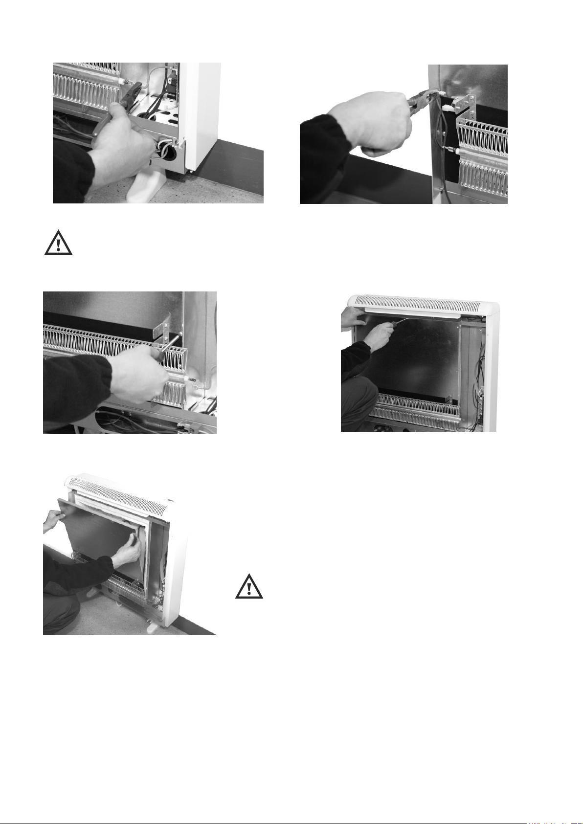
7. - Disconnect the aluminum heating element by removing the FAST-ON terminal on each end of the element.
WARNING Steel edges can cut.
Next unscrew the inner panel and remove it.
CAUTION In the interior part of this inner panel there is a very
delicate thermal insulation MICROTHERM panel. It has to be handled with
extreme care. AVOID TOUCHING IT.
Page 6
5
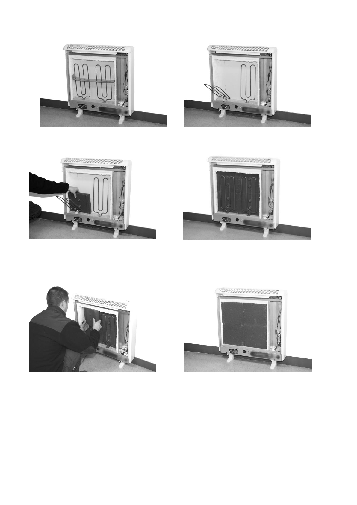
8. Do not disconnect the electrical heating elements. Remove the packing cardboard. Lift and tilt the elements outwards being
careful not to damage the insulation on the bottom of the heater.
9. - Place the storage bricks carefully, with the flat side facing the back of the heater. Arrange two row levels of bricks.
10. Place the heating elements back into their original position. Place the other two rows of storage bricks with the flat side
facing out and always on the heating elements supporting tabs.
Page 7
6
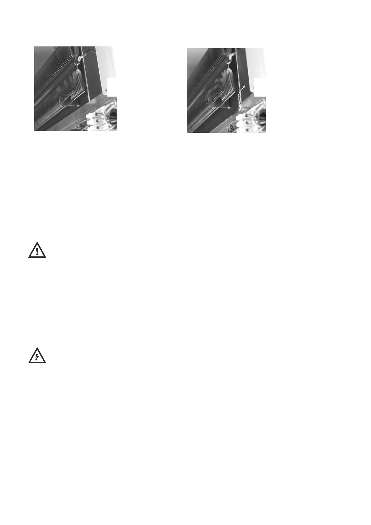
11. Replace the inner front panel. If the bricks have been fitted correctly you will have no difficulty in replacing the panel. Make
sure the bottom edge of the inner panel is inside the front lip of the heater. Please see below:
12. - Reconnect the two FAST-ON terminals to the aluminum heating element attached to the inner panel at both ends.
13. – When replacing the exterior front panel, align the 2 plastic upper pegs on the heater with the holes in the exterior panel.
Push the top up into place and push the bottom in until it rests on the plastic feet.
14. - Replace the front panel with screws.
RELOCATION
WARNING: Relocation to another location must be carried out by an experienced technician.
If during reinstallation the thermal insulation shows any sign of damage, it must be removed and replaced by an identical part.
MANUALLY RESET TEMPERATURE LIMITER
This heater employs a manually reset temperature limiter (see LR in the connection diagram).
This safety device operates when high temperatures are reached at the top of the heater. It requires re-setting manually:
Let the heater cool. The cause of overheating should be investigated.
WARNING: Re-setting manually must be carried out only by an experienced technician.
Turn off the heater at the circuit breaker.
Take off the front panel by removing the two screws located at the bottom. Find the limiter LR in the connection diagram and
push the small pin until a click is heard.
RIGHT
POSITION
WRONG
POSITION
Page 8
7
3. - OPERATING INSTRUCTIONS
CAUTION: DO NOT USE THIS HEATER TO DRY CLOTHES. Do not cover this heater at any time.
CONNECTION / DISCONNECTION
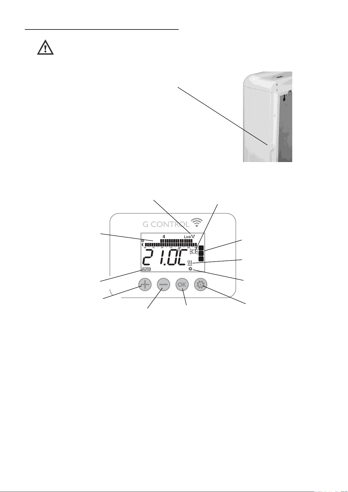
Power switch. All models are equipped with a switch on the back
side panel. It is used to connect and disconnect ECOMBI SSH.
KEYBOARD:
ON/OFF
Once the heater is connected to a main supply you can turn the heater ON by switching the main ON/OFF switch positioned at
the rear right side of the heater as shown above.
BACKLIGHT
Pressing any button, the display will illuminate with a soft white colour. After certain time if no buttons are pressed the display
backlight will turn off.
Operating mode.
Button “+”
Press the key to increase
different values.
Button “-”
Press the key to decrease
different values.
“Config / Prog” Button
Press the button to programme
and configure the SSH storage
heater in AUTO Mode.
“OK” Button
Press the button to select
operation mode: Auto, Manual,
Off, and to set the value of the
different parameters.
G-Control Hub
connection indicator.
Heating on indicator.
Daily Programming:
Temperature level for each
time interval (1h) of the day.
Current set point
temperature in AUTO
mode.
Current Charge Level.
Open Windows Detection
indicator.
Page 9
8
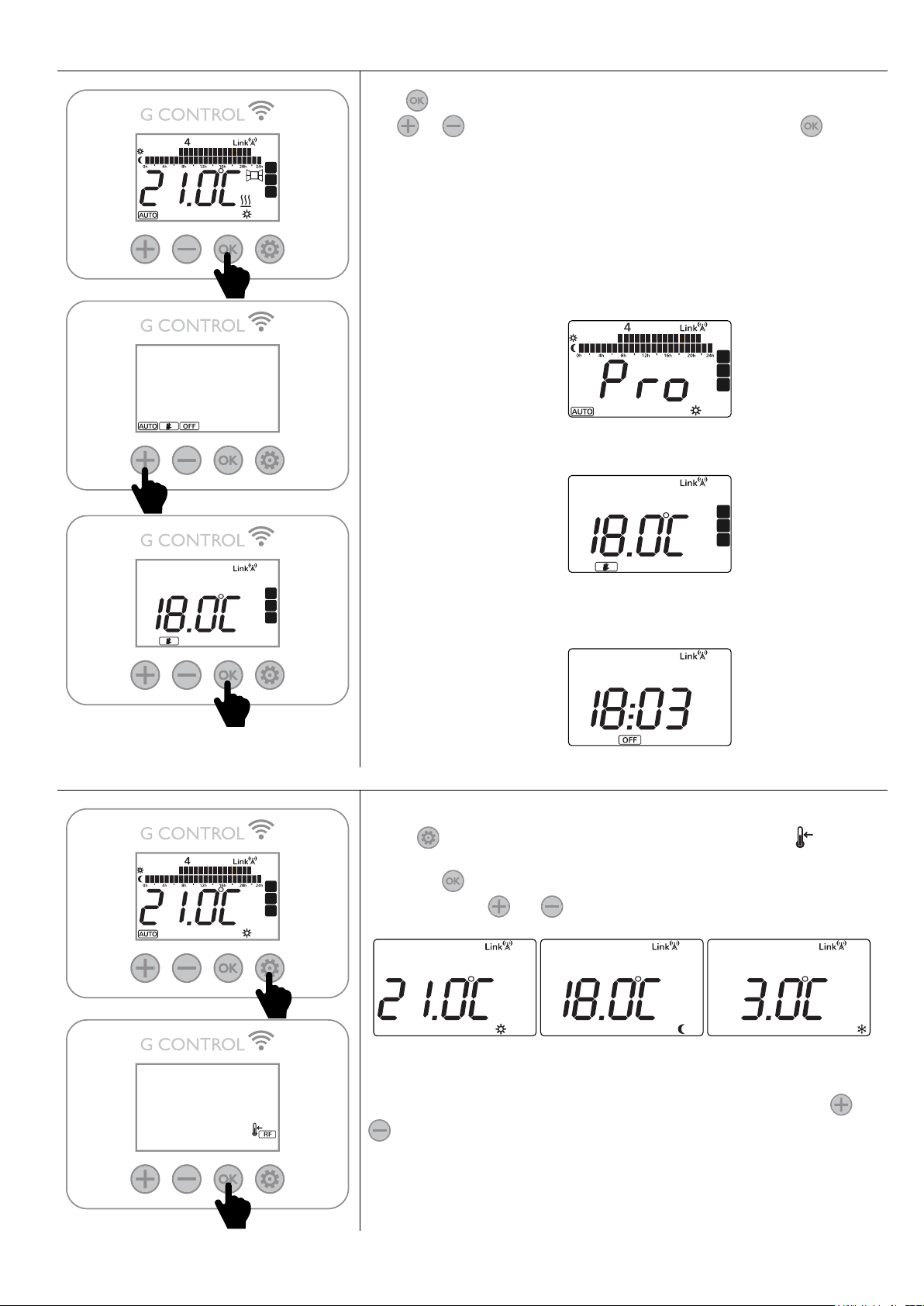
OPERATION MODES SELECTION
Press , the operation modes are displayed, with the selected one flashing.
Use or to select the desired operation mode. Confirm with .
The heater has three different operation modes: Auto, Manual override and
Standby Mode.
- Auto: The setpoint temperature varies according to the weekly
schedule setup in the unit. 3 different temperature levels (Comfort,
Moon and Frost Protection) can be selected for each time interval (1
hour) to adjust the temperature in the room to the habits and needs of
the different users.
- Manual Override: the storage heater will maintain the temperature
set point and will ignore the pre-set program.
- Standby Mode: the storage heater doesn't maintain any set
temperature or run any programs, keeping the time settings configured
previously.
AUTO MODE – Temperature Level
To modify the set temperatures within the program permanently, press and
release until the display shows the flashing temperature symbol .
Now press to select the temperature you want to change, COMFORT or
ECONOMIC. Use and to select the desired temperature.
You can temporary change the set temperature for the time period too. To do
this, increase or decrease the current temperature simply by pressing and
. Once the time period finishes, the temperature will revert back to the
programmed set temperature.
Page 10
9
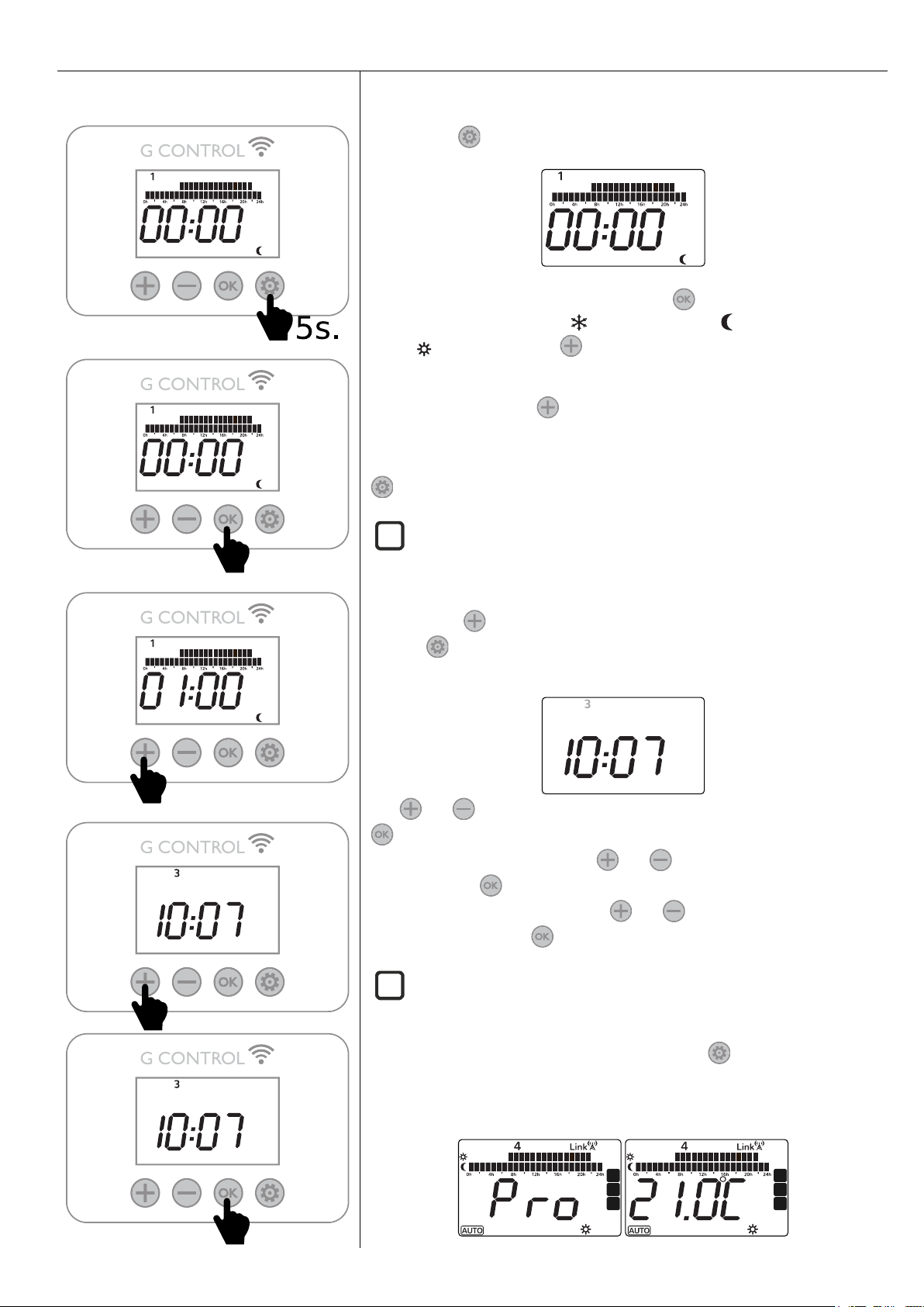
AUTO MODE – Programming & Time Setting
Programming
Enter programming:
Select temperature level:
Next 1 hour Time Interval:
Time Setting
PROGRAMMING
Press & Hold until the following is shown.
The first segment will start to flash. By pressing you can select whether you
want a Frost Protection setting (3°C), Moon setting (18°C) or Comfort
setting (21°C). Now press to move to the next 1hour time interval.
Once you've gone through all the time intervals for day 1, you will automatically
start on day 2 by pressing . Repeat the above steps until you go through all 7
days.
If you do not desire to modify the programming of a day within the week, press
to go through the next day.
SSH will not charge in Frost Protection time intervals.
TIME SETTING
After pressing when the last time interval for day 7 is flashing or after
pressing in day 7, the time setting configuration starts. The following is
shown with the day of the week flashing.
Use and to select today's date. 1=Monday, 2=Tuesday, Etc. and Press
to confirm.
Now the hours start to flash. Press and until you reach the correct time
(hour) and Press to confirm.
Now the minutes start to flash. Press and until you reach the correct
time (minutes) and Press to confirm.
If the device is associated with a G-Control Hub, the adjustment of time is
removed and the time in the G-Control Hub is configured in the heater automatically
If you do not desire to modify the time setting, press to exit. After setting
the time, the display will show and start to run the program and will flash
between the set temperature for the current day, time interval and the word
Pro to indicate the heater is running the set program.
i
i
Page 11
10
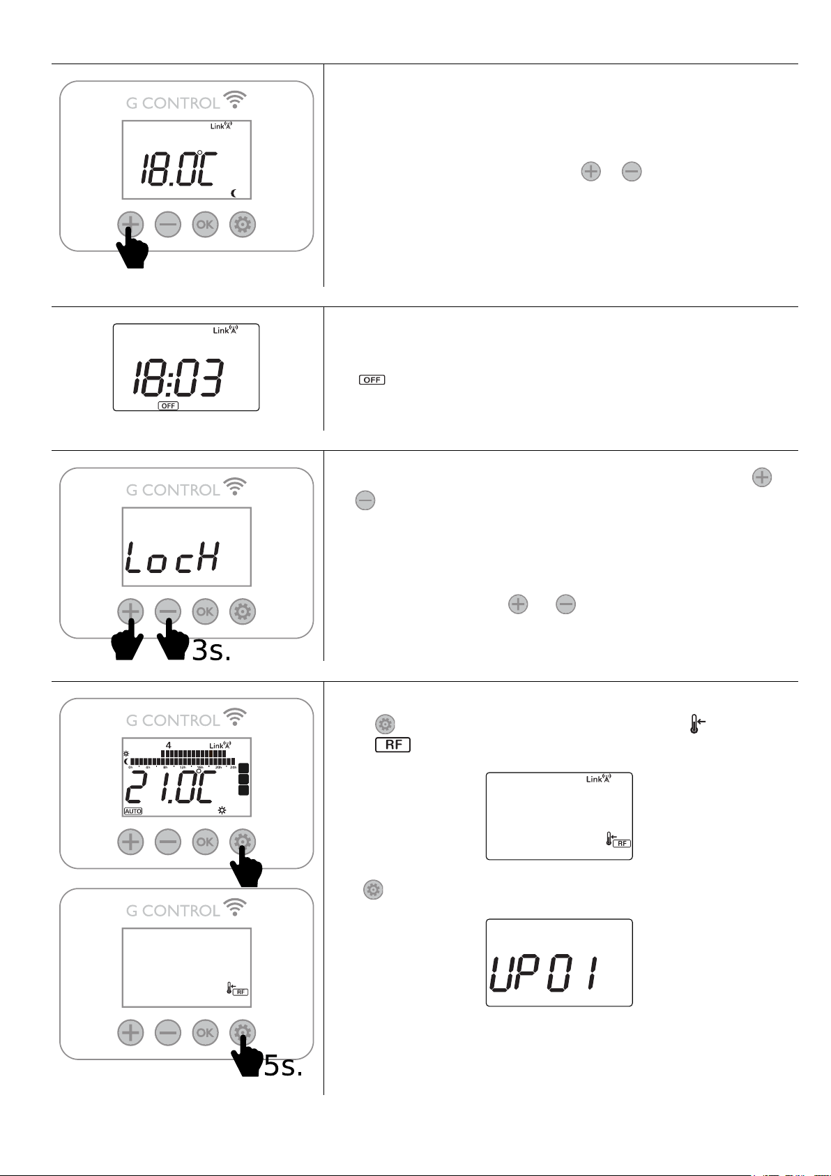
MANUAL OVERRIDE
Increase temperature set point
In manual mode, the unit will maintain the temperature set point and will ignore
the pre-set program. SSH will maintain the selected temperature for the 24
hours of the day. Use this mode, when the same temperature is desired for
every hour in the week.
To modify the temperature set point, press or until the desired
temperature is shown.
STANDBY MODE
It is possible to put SSH in standby mode where the heater does not maintain
any set temperature or run any programs. It keeps the time settings configured
previously. When in this mode, the heater will display the current time and the
icon .
KEYBOARD LOCK
Lock / Unlock
During any operation mode, it is possible to lock the keyboard by holding
and simultaneously for 3 seconds. When the keyboard is locked, the
message Lock will be displayed.
When the keyboard is locked, if any button is pressed, the display will show
“Lock” and the unit will not respond.
To unlock the keyboard, press and simultaneously for 3 seconds.
GENERAL SETTINGS
It is possible to modify the general settings. During any operation mode, press &
release , the display shows the flashing temperature symbol and the RF
symbol .
Hold for 5 seconds until the display shows UP01.
Page 12
11
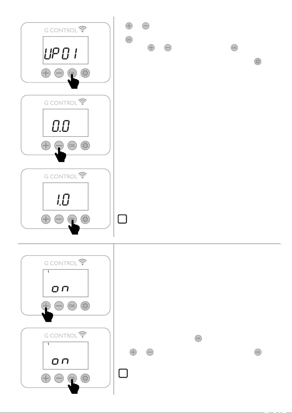
Access to the parameter
Change Value: Decrease
Confirm Value
Use and to move on through the different parameters.
Use to access the parameter you want to modify. Change the value using the
navigation keys and . Confirm the new value with .
It is possible to save the changes and exit at any moment by pressing .
SSH general parameters that can be modified by the user are detailed below:
- UP01: Initial % of storage charge.
- UP02: Starting time of reduced (off-peak) rate electric period.
- UP03: Ending time of reduced rate electric period.
- UP04: Starting time of the second reduced rate electric period. (if not
available set up 00:00).
- UP05: Ending time of the second reduced rate electric period. (if not
available set up 00:00).
- UP06: Charging days during the week.
- UP07: Temperature ambient sensor correction (values from -5ºC to 5ºC).
- UP08: Maximum working period of the balancing heating element in on
peak electric period. Set up this value to “0” to cancel the balancing
heating element operation in on peak electric periods. With balancing
heating operation cancelled, the charge correction will not operate and
the same charging level will be applied every day. (Default 16 hours)
- UP09: Excess of temperature protection during the charge, Degrees
higher than the comfort set point temperature (Auto Mode) or the
manual set point temperature (Manual Mode) when the charge is
interrupted. (Values 1,2,3,4 & 5).
- UP10: Degrees Celsius or Fahrenheit. (Values: ºC – F).
- UP11: Open Window Detection Activation. (On/Off).
- UP12: Adaptive Start Control Activation (On/Off).
- UP13: Kind of temperature control. Recommended & default PID.
ECOMBI SSH does not change automatically from summer time to winter time
or vice versa when not connected to the internet. Depending on the tariff it may be
necessary to change the clock settings to fit these two timings.
WEEKLY CHARGE PERIOD SETTING
Weekly charging days (UP06 parameter)
Charging/Not Charging day 1
Advance to the next day
Access to the general setting to modify the charging period of your SSH storage
heater. (See “General Settings” above). By default, 00:00 to 07:00 charge period
is set in every day in the week.
Charge period
Two charging periods can be selected in the electronic control of your SSH.
- 1º Charging period: UP02 to UP03. (00:00 to 07:00 by default).
- 2º Charging period: UP04 to UP05. (Disabled by default, 00:00 to 00:00).
Weekly charging days
It is possible to select which days SSH will charge and which days it will not.
Access to the UP06 parameter to modify the days you want your SSH takes a
charge. (By default, 7 days of the week).
Access to UP06 parameter by pressing . The first day indicator in the top of
the display and the charge condition (On/Off) is displayed.
Press and to change the charge condition for this day. Press to go
on through the days.
SSH will not charge in Frost Protection time intervals.
i
i
Page 13
12
SMART STORAGE HEATER:
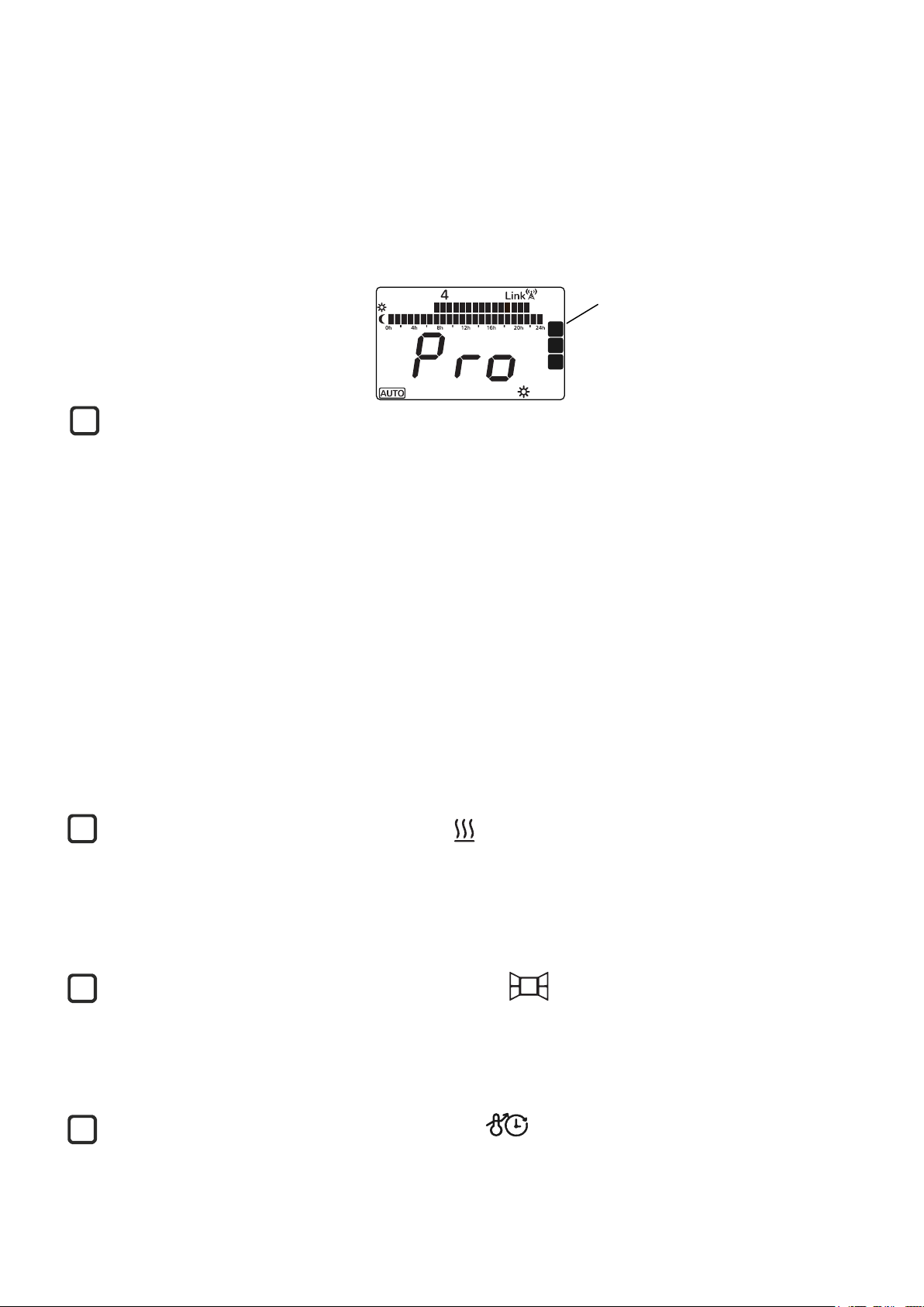
SSH optimizes the energy management and consumption and provides the heat demand requested by the user in each period of
time reaching the desired comfort.
Smart charging control
SSH allows optimizing the energy management and consumption using a linear regression model based on the temperature
registered in the core of SSH to determine the current % of the storage heater charge and use this information to charge only
the heat necessary to supply the daily heat demand and avoid unnecessary energy consumption.
The charge level is monitored every time by the electronic control and represented in the display by the dots in the right side of
the display. 5 dots represent a fully charge storage heater.
While SSH is charging, the last dot is flashing at the top right part of the display.
Protection for excess of temperature in the room
In order to achieve maximum savings and avoid unnecessary energy consumption, if, during the charging period, the temperature
in the room exceeds the temperature set up in SSH for that room, then the charging will be interrupted until the temperature in
the room decreases.
Charge correction
The % of the storage heater charge is corrected automatically by SSH software. If working hours of balancing element is higher
than a certain value, storage heater charge will be increased by a certain %. On the other hand, if balancing element working
hours does not exceed this value, storage heater charge level is reduced by the same %.
This behaviour adapts the consumption to the real thermal needs, allowing the maximum level of energy savings at the required
comfort. The set-up temperature is independent of the Storage Heater level of charge. Initial setting for charge is 80%. This value
can be modified by entering “General Settings” part and modify the initial % of storage charge according to UP01 setting.
Balancing Heating Element
If the energy discharged with natural convection is not enough to satisfy the heat demand of the room where SSH is installed, a
balancing heating element incorporated in the SSH body will be connected providing additional heating to the room if necessary
to supply the heat demand of the room. The maximum working period of the balancing heating element during on-peak electric
electric periods can be adjusted and cancelled by modifying UP08 parameter. (please go to “General Settings”).
When the balancing heating element is on, the symbol is displayed.
*Storage Heater and Balancing Heating Element will never work at the same time.
Open Window Detection
With open window detection activated, the balancing element operation will be disconnected automatically when a sharp
decrease in temperature in the room is detected avoiding energy wastage.
When Open Windows Detection function is working, the icon is displayed.
Adaptive Start Control
With adaptive start control activated, SSH electronic control analyses the heating requirements of the room where it is installed
using this information to turn on the balancing heating element in advance in order to reach the set point temperature at the
desired time.
When Adaptive Start Control function is working, the icon is displayed.
iii
i
Current Charge Level
Page 14
13
DEFAULT SETTINGS & RESET
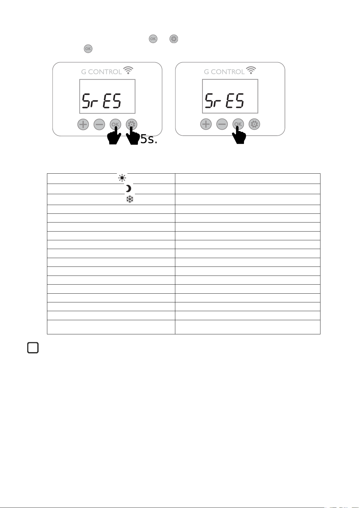
To reset the unit to factory default settings, press and simultaneously for 5 seconds until the message SrES is displayed.
Confirm the reset with .
Default Values
Sun: Comfort temperature
21ºC
Moon: Economic temperature
18ºC
Frost protection temperature
3ºC
UP01: Initial % of storage charge
80%
UP02: Starting time off peak period 1
00:00
UP03: Ending time off peak period 1
07:00
UP04: Starting time off peak period 2
00:00
UP05: Ending time off peak period 2
00:00
UP06: Charging days of the week
Default -> Charging 7 days of the week.
UP07: Ambient sensor Offset
0ºC
UP08: Max. Balancing element – working period
16 hours
UP09: Overtemperature protection
2ºC
UP10: Temperature Unit
ºC
UP11: Open Window Detection Function
Off
UP12: Adaptive Start Control
Off
UP13: Kind of temperature control
PID
Default Programming
Comfort: 07:00 to 22:00.
Eco: 00:00 to 07:00 & 22:00 to 00:00.
Incorrect time settings, erroneous programming of the reduced rate time and too high temperature settings may result in
a high cost of your electricity bill.
i
Page 15
14
4.- REMOTE OPERATION USING THE WIFI G-CONTROL HUB
It is possible to control the full operation of the unit remotely with Gabarron-Elnur app or app-web. The unit must be
connected to a Wifi G-Control Hub connected to the internet to use this feature.
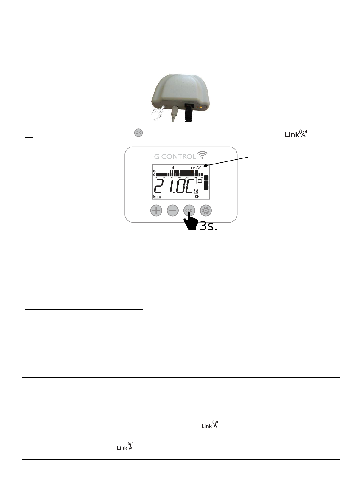
4.1 To associate the unit to the G-Control Hub, the discovery mode of the hub must be activated. Press the associate button at
the back of the Gateway for 3 seconds. An orange flashing light every second indicates association mode.
4.2 With the hub in association mode, press on the storage heater for 3 seconds until the Link symbol is shown.
You control and adjust the programming and temperatures on the SSH via the Gabarron-Elnur app.
4.3 To disassociate the unit, a reset of the unit must be realized. See “DEFAULT SETTING & UNIT RESET”. When the
storage heater is reset, it will remove the programming and revert back to the default settings and also disassociate from the RF
network and G-Control Hub.
5.- TROUBLESHOOTING
ECOMBI SSH does not heat.
Please check it is connected and switched on.
Make sure the device is not covered or the lower air inlets are not obstructed. The LR safety limit
may be activated; in this case it is necessary to reset it manually. Please contact technician.
ECOMBI SSH does not reach
set up temperature
Make sure that adequate temperature is selected.
Make sure the storage heater is sized correctly for heat loss.
Err Message in display
Please contact technician.
Keyboard does not respond
If the “Lock” message is displayed, the thermal radiator keyboard is locked. Hold “+” and “-” buttons
simultaneously for 3 seconds to unlock the keyboard. (See Keyboard Lock Section).
ECOMBI SSH does not
communicate with the G
Control Hub.
Check the unit is associated, the symbol must be shown on the display LCD.
For distances greater than 30 metros and 2-3 walls, associate first the closest units. Each unit can
work as signal extender.
If symbol is flashing, check the G Control Hub connexion to the network, and if any other
device in the RF Net that could be working as signal extender has been removed.
Page 16
15
6.- CLEANING MAINTENANCE INSTRUCTIONS
Before cleaning, make sure the power has been turned off at the circuit breaker panel and that the heating element of the heater
is cool.
Occasionally, clean dust with a dry, soft cloth. Do not use any solvent or abrasive product for cleaning.
When the Heating season is finished, please disconnect the device by turning off the power switch located at the right back of
the unit or at the circuit breaker.
Any other servicing should be performed by an authorized technician.
ECOMBI SSH has been manufactured under a fully assured quality system and using environmentally friendly processes.
Once its useful life is finished please take the device to a recycling depot so that its components can be recycled in an
appropriate way.
7.- MAIN COMPONENTS LIST
Storage Heating Element (All except ECOSSH158)
Ref. 15190091
Switch
Ref. 46100530
Storage Heating Element (ECOSSHI58)
Ref. 15190875
PCB
Ref. 15191870
450W Balancing Heating Element (ECOSSHI58)
Ref. 15190105
Core Sensor
Ref. 15192140
600W Balancing Heating Element (ECOSSH208)
Ref. 15190110
Room Sensor
Ref. 46102195
900W Balancing Heating Element (ECOSSH308)
Ref. 15190120
110ºC Balancing Element Limiter
Ref. 15190725
1200W Balancing Heating Element (ECOSSH408)
Ref. 15190130
135ºC Cut Out Manually Limiter
Ref. 10190460
8.- CONNECTION DIAGRAMS
i
LE BALANCING ELEMENT LIMITER
LR CUT OUT MANUALLY LIMITER
Page 17
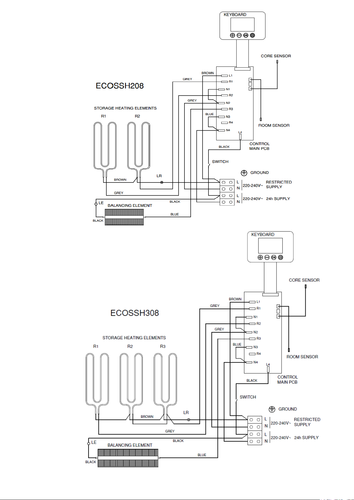
16
LE BALANCING ELEMENT LIMITER
LR CUT OUT MANUALLY LIMITER
LE BALANCING ELEMENT LIMITER
LR CUT OUT MANUALLY LIMITER
Page 18
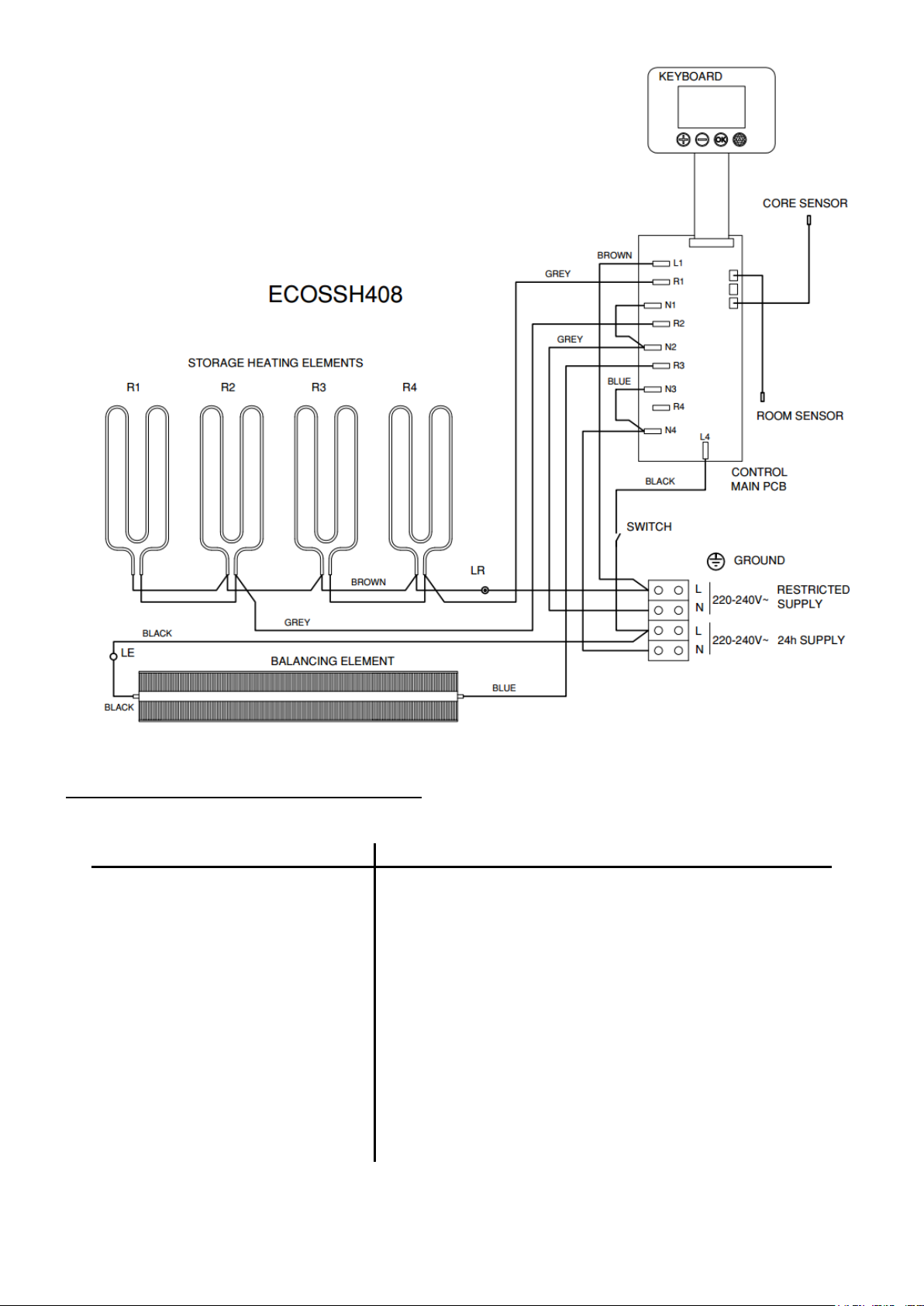
17
9.- THECNICHAL FEATURES
* Storage heater elements and balancing heating element will never operate at the same time.
Modelo
ECOSSH158
ECOSSH208
ECOSSH308
ECOSSH408
CONNECTION
230 - 240V ~
230 - 240V ~
230 - 240V ~
230 - 240V ~
*BALANCING ELEMENT OUTPUT 230/240
450/490W
600/653W
900/980W
1200/1307W
STORAGE HEATER OUTPUT 230/240
975/1062W
1300/1415W
1950/2123W
2600/2831W
CHARGE PERIOD
7.6 – 7h
7.6 – 7h
7.6 – 7h
7.6 – 7h
CHARGING
7.4 kWh
9.9 kWh
14.9 kWh
19.8 kWh
INSULATION
Class I
Class I
Class I
Class I
LENGTH
55cm
66cm
89cm
111cm
HEIGHT
73cm
73cm
73cm
73cm
DEPTH
18cm
18cm
18cm
18cm
WEIGHT
59kg
77kg
112kg
147kg
NUM. OF BRICKS 7,5kg
- 8 12
16
NUM. OF BRICKS 11,5kg
4 - -
-
BRICK PACKAGE
11072
11016
11016
11016
LE BALANCING ELEMENT LIMITER
LR CUT OUT MANUALLY LIMITER
Page 19
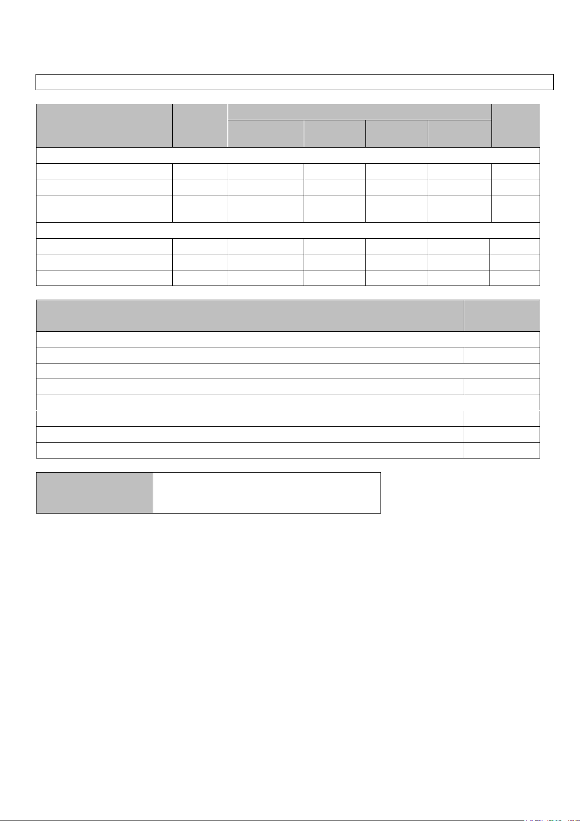
18
PRODUCT FICHE
ErP
MODEL(S): GABARRON ECOSSH158, ECOSSH208, ECOSSH308, ECOSSH408
Item
Symbol
Value
Unit
ECOSSH
158
ECOSSH
208
ECOSSH
308
ECOSSH
408
Heat Output
Nominal heat output
P
nom
0.55
0.75
1.125
1.5
kW
Minimum heat output
P
min
N.A.
N.A.
N.A.
N.A.
kW
Maximum continuous heat
output
P
max,c
0.55
0.75
1.125
1.5
kW
Auxiliary electricity consumption
At nominal heat output
el
max
0.000
0.000
0.000
0.000
kW
At minimum heat output
el
min
0.000
0.000
0.000
0.000
kW
In standby mode
el
SB
<0.0005
<0.0005
<0.0005
<0.0005
kW
Item
Value. All
models
Type of heat input
Electronic heat charge control with room and/or outdoor temperature feedback
Yes
Type of heat output / room temperature control
Electronic room temperature control plus week timer
Yes
Other control options
Room temperature control, with open window detection
Yes
With distance control option
Yes
With adaptive start control
Yes
Contact details
ELNUR, S.A.
Travesía de Villa Esther, 11
28110 – Algete (Madrid), Spain
Commission Regulation (UE) 2015/1188 of 28 April 2015. Ecodesign requirements for electric
storage local space heater.
Page 20
Supplier:
ELNUR UK Ltd.
Unit 1, Brown Street North
Leigh, Lancashire. WN7 1BU
Telephone +44(0)1942 670119
www.elnur.co.uk
Manufactured by:
ELNUR S.A.
Travesía de Villa Esther, 11
28110, Algete - Madrid
Telephone +34 916281440
As part of the policy of continuous product improvement the manufacturer reserves the right to alter specifications without notice.
15190016 R3
The symbol on the product or in its packaging indicates that this product may not be treated as household
waste. Instead it shall be handed over to the applicable collection point for the recycling of electrical and
electronic equipment. By ensuring this product is disposed of correctly, you will help prevent potential
negative consequences for the environment and human health, which could otherwise be caused by
inappropriate waste handling of this product. For more detailed information about recycling of this product,
please contact your local city office, your household waste disposal service or the shop where you
purchased the product. These instructions are only valid in the EU member states.
 Loading...