

Page 1
INSTALLATION INSTRUCTIONS AND USER GUIDE
DILIGENS
WIFI THERMAL RADIATORS
DIL4GC DIL10GC
DIL6GC DIL12GC
DIL8GC DIL14GC
Please read these instructions before installing or using this appliance for the first time. These instructions must be followed for the safe installation of the radiator. Any
problem, fault or damage caused by the non-observance of these instructions will not be covered under the manufacturer’s warranty. This manual should be retained with the
appliance by the user for future reference.
Page 2

2
1. WARNING Please read these instructions before installing or using this appliance for the first time.
The warranty of the heater will not cover any damage caused by non-observance of any of these
instructions.
The instructions should be retained for future reference. This guide must be kept and given to any new
owner.
This appliance can be used by children aged from 8 years and above and persons with reduced physical,
sensory or mental capabilities or lack of experience and knowledge if they have been given supervision or
instruction concerning the use of the appliance in a safe way and understand the hazards involved. Children
must not play with the appliance. Cleaning and user maintenance must not be made by children without
supervision.
Children aged from 3 years and less than 8 years shall only switch on/off the appliance provided that it has
been placed or installed in its intended normal operating position and they have been given supervision or
instruction concerning use of the appliance in a safe way and understand the hazards involved. Children aged
from 3 years and less than 8 years shall not plug in, regulate and clean the appliance or perform user
maintenance.
Children of less than 3 years should be kept away unless continuously supervised.
Please check that the voltage in the rating label fits the power supply.
The use of these heaters is forbidden in any area where there is a presence of gases, explosives or
inflammable objects.
Do not use this heater to dry clothes. Do not cover this heater or put objects in contact with it.
Neither the connecting cable nor any other object must come into contact with the hot unit.
Do not cover this heater at any time.
The air outlet at the top of the thermal radiator and the air inlet at the bottom are provided to ensure the
most efficient operation of the appliance. They also protect the heater from overheating; therefore, it is
essential that at no time are they covered.
This heater should be switched off at the isolating switch before any repair work is carried out.
The installation must be carried out in accordance with the current electrical regulations.
Should the heater be moved and reinstalled it is essential that the work is carried out by a fully qualified
technician.
The heater should not be installed just below an electrical socket.
The appliance must be installed in such a way that it is impossible for anyone using a bath or shower, to
touch the controls.
The heater is fitted with a flexible cable size 3 x 1.00 mm² for electrical connection. It may be used to
connect the heater to the fixed wiring of the premised through a suitable connection box positioned
adjacent to the heater.
The supply circuit to the heater must incorporate a double pole isolating switch having a contact separation
of at least 3 mm.
If the flexible power cable for this unit is damaged, it may only be replaced by a repair workshop recognised
by the manufacturer, as special tools are necessary.
This appliance must be earthed.
All models are supplied with an electrical interrupt cut-out. This will switch off the heater if, for any reason,
it overheats. Should the cut-out operate, turn the heater off and remove the cause for the overheating. The
cut-out will be reset automatically.
The presence of air particles of smoke, dust and other pollutants could, in time, discolour the walls and
surfaces around the heater.
CAUTION — Some parts of this product can become very hot and cause burns. Particular attention must
be given when children and vulnerable people are present.
Page 3
3
2. - INSTALLATION INSTRUCTIONS
- Open the package and check that it is the correct model and it is in good condition.
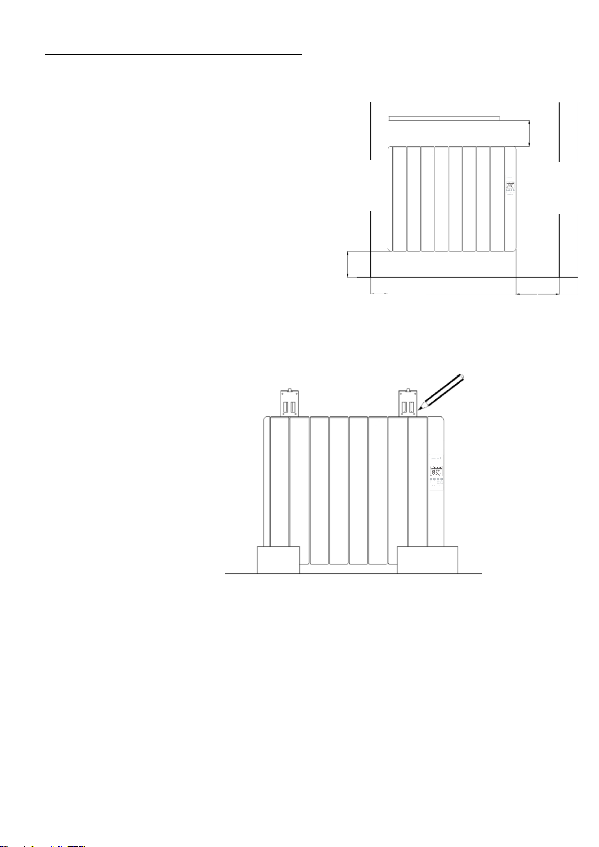
- To obtain optimum performances it is necessary to maintain a
minimum clearance of
15 cm between the radiator and any inflammable material as furniture,
curtains etc.
- The rest of clearances required to maintain are indicated on the
following figure:
- The studs and screws to attach the
supports are in the accessories bag.
- Hang the unit on the hooks of the
brackets.
- By turning the screw the metallic
square will go downwards, retaining the
heater. Repeat this on the other bracket.
Mark the fixing points on the
wall using a pencil through the
two fixing holes in the square
brackets and perform
corresponding bores.
Position and fix the brackets at the correct
distance from the floor. It is possible to use
the radiator as measuring unit by positioning
it on two polyester package elements and
placing two supports above as indicated on
the figure:
Shelf
Minimum 10cm
Minimum
15cm
Minimum 25cm
Control panel side
Minimum 15cm
Closest
object
to the
left end
Closest
object
to the
right end
Page 4
4
3. - USING THE THERMAL RADIATOR
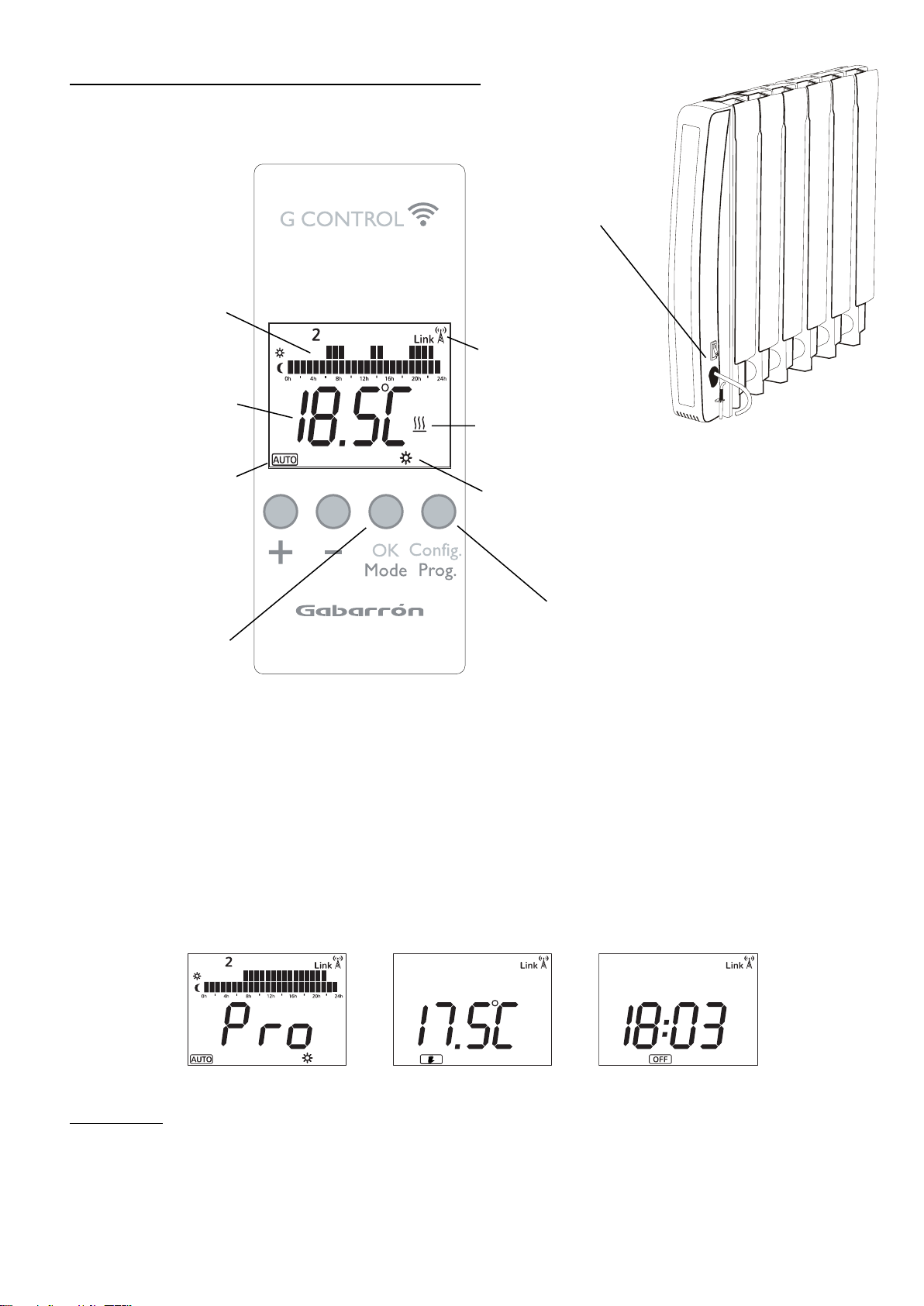
GREEN BACKLIGHT
Pressing any button the display will illuminate with a soft green colour. After certain time if no buttons are pressed the display
backlight will turn off.
OPERATING MODES
The heater has three different operation modes that may be selected by pressing the OK/Mode button, these are: Auto,
Manual override and OFF.
AUTO MANUAL override OFF
3.1. ON/OFF
Once the heater is connected to a main supply you can turn the heater ON by switching the main ON/OFF switch positioned at
the rear right side of the heater as shown above.
Config / Prog Button
Press the button to programme
and configure the thermal radiator
in AUTO Mode.
OK / Mode Button
Press the button to select
operation mode: Auto, Manual,
Off, and to set the value of the
different parameters.
Main switch.
All models are
equipped with one
switch on the back
surface allowing the
heater disconnection.
Operating mode.
Daily Programming:
Temperature level for each
time interval (1h) of the day.
Temperature setpoint.
Heating on indicator.
G-Control Hub
connection indicator.
Current set point
temperature in AUTO
mode.
Page 5
5
3.2. SETTING THE TIME
We start by first setting the Day and Time.
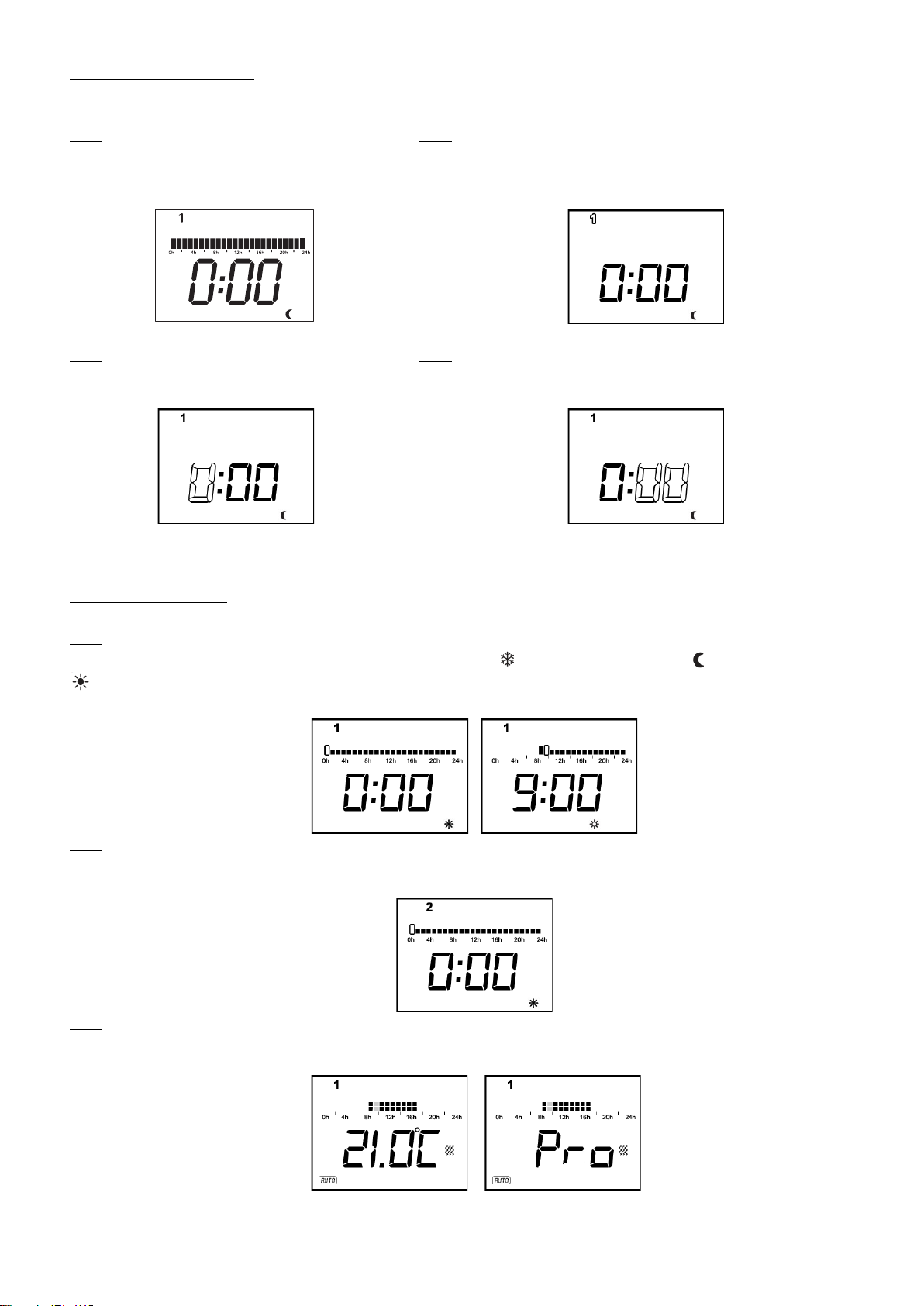
3.2.1 You can do this by Press & Holding the
Config/Prog. button until the following is shown.
3.2.2 Press & Release the Config/Prog. button again and the day of
the week starts to flash. Using the "+" and "-" buttons select today's
date. 1=Monday, 2=Tuesday, Etc. and Press the OK/Mode button.
3.2.3 Now the hours start to flash. Press the "+"
and "-" button until you reach the correct time
(hour) and Press the OK/Mode button.
3.2.4 Now the minutes start to flash. Press the "+" and "-" button until
you reach the correct time (minutes) and Press the OK/Mode button.
If the device is associated with a G-Control Hub, the adjustment of time is removed and the time in the G-Control Hub is
configured in the heater automatically.
3.3. PROGRAMMING
Press OK/Mode to select the Auto Mode. By default, the background economic temperature is applied in all time intervals.
3.3.1 Press & Hold the Config/Prog. button until the following is shown. The first segment will start to flash. By pressing the
OK/Mode button you can select whether you want a Frost setting (5°C), Background setting (17°C) or Comfort setting
(19°C). Now press the "+" button to move to the next 1 hour time interval.
Note: These temperatures can be changed later without adjusting the times.
3.3.2 Once you've gone through all the time intervals for day 1, you will automatically start on day 2. Repeat the above steps
until you go through all 7 days. Once you have configured the desired programming, press Config/Prog button to exit
programming.
3.3.3. After going through all the days the display will show and start to run the program and will flash between the set
temperature for the current day, time interval and the word Pro to indicate the heater is running the set program.
.
Page 6
6
3.4. TEMPERATURE LEVELS
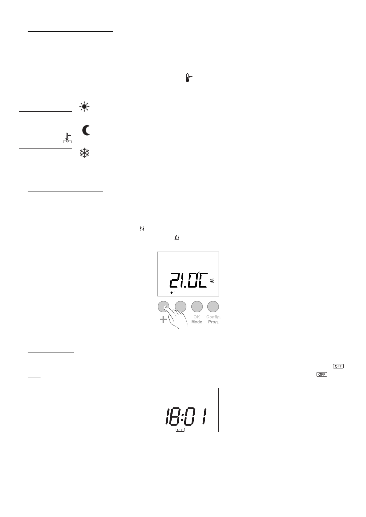
In the AUTO mode, you can temporary change the set temperature for the time period. You can increase or decrease this
temperature simply by pressing the "+" or "-" buttons. Once the time period finishes, the temperature will revert back to the
programmed set temperature.
You can modify the set temperatures within the program permanently too, to do this, Press & Release the Config/Prog.
button until the display shows the flashing temperature symbol . Now press the OK/Mode button to select the temperature
you want to change, COMFORT or ECONOMIC, and use the "+" or "-" button to select the desired temperature.
COMFORT: Recommended for the periods of time when the user is at home and the maximum
comfort is required. Default value 19ºC.
ECONOMIC: Recommended for nights and small away periods of time. Default value 17ºC.
FROST PROTECTION: Recommended for long away periods of time. Default value 5ºC.
It is possible to exit of temperature level configuration by pressing the Config/Prog button at any time.
3.5. MANUAL OVERRIDE
In manual mode, the heater will maintain the temperature set point and will ignore the pre-set program. By default, the initial
temperature set point is 19°C.
3.5.1 To modify the temperature set point, Press the "+" or "-" button until the desired temperature is shown. The heater will
now cycle on and off and maintain this temperature setting. If the room temperature goes below the set temperature, then the
heaters element will turn on and the symbol will be shown. If the room temperature is higher than the set temperature, then
the heaters element won't turn on and the heating symbol won't be displayed.
3.6. OFF MODE
It is possible to put the heater in standby mode where the heater doesn't maintain any set temperature or run any programs,
keeping the time settings configured previously. When in this mode, the heater will display the current time and the word .
3.6.1 To select the OFF mode, Press & Release the OK/Mode button until the display shows the current time and .
3.6.2 If the heater is turned off via the main switch at the back of the heater or if the power to the heater is removed and the
heater is not connected to a Wifi G- Control Hub then the time setting within the heater will be lost.
Page 7
7
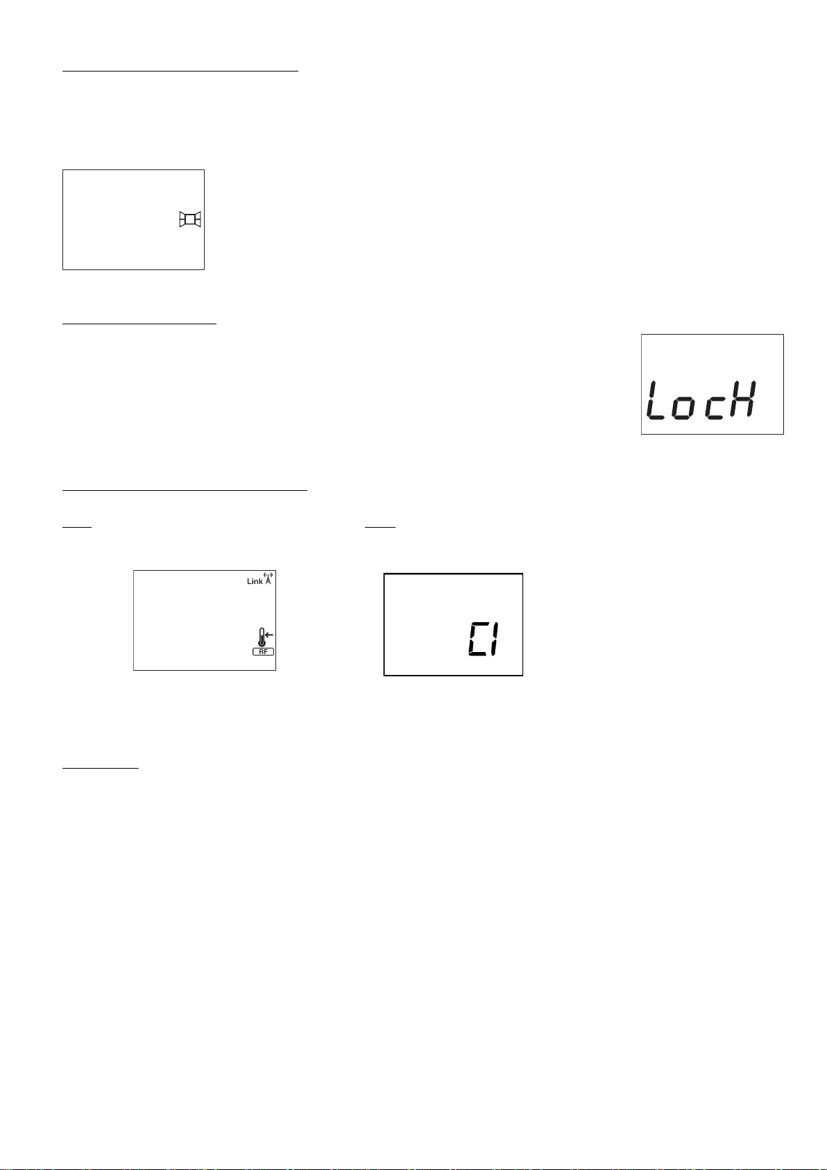
3.7. OPEN WINDOW DETECTION
With open window detection activated, the heating element will be disconnected automatically when a sharp decrease in
temperature in the room is detected. Heating elements will be disconnected for 30 minutes when a decrease of 2,4ºC in less
than 4 minutes is detected. After 30 minutes, the radiator returns to the prior operation mode.
It will be shown in the displays as follows:
Note: To activate the window detection please refer to C5 in 3.9. ADVANCED CONFIGURATION section.
3.8. KEYBOARD LOCK
In every operation mode, it is possible to lock the keyboard by holding “+” and “-” buttons
simultaneously for 3 seconds. When the keyboard is locked, the message Lock will be displayed.
When the keyboard is locked, if any button is pressed, the display will show “Lock” and the unit will
not respond.
To unlock the keyboard, press the “+” and “-” buttons simultaneously for 3 seconds.
3.9. ADVANCED CONFIGURATION
3.9.1 To access to advanced configuration menu,
Press & Release Config/Prog button until the
following is displayed:
3.9.2 Hold the Config/Prog button for 5 seconds, the first parameter
(C1) will be displayed. To select the next parameter, press the "+"
button.
To modify the value of the parameters,
press the OK/Mode button. Then use the
"+" and "-" buttons to select the different
options. Press the Ok/Mode button again
to set the value.
Use the same procedure to modify the others parameters where necessary. It is possible to exit of advanced configuration by
pressing the Config/Prog button at any time.
Parameters
- C1. Fahrenheit or Celsius Degrees.
The LCD displays the temperature unit selected: ºC or ºF.
- C2. Control Adjustment.
The kind of temperature control can be modified with this parameter:
PID, Hysteresis 0,25ºC, Hysteresis 0,35ºC, Hysteresis 0,50ºC, Hysteresis 0,75ºC.
- C3. Correction of ambient temperature measures.
If there is a difference between an external thermometer and the temperature displayed by the unit, with C3
parameter it is possible to influence on the sensor in order to balance the difference. (-3ºC to +3ºC in 0,1 steps).
- C4. Firmware version.
Information about the current firmware version of the unit.
- C5. Open Window Activation
ON/OFF. With the parameter in ON, the open window detection is activated.
Page 8
8
4.- REMOTE OPERATION USING THE WIFI G-CONTROL HUB
It is possible to control the full operation of the unit remotely with Gabarron-Elnur app or app-web. The unit must be
connected to a Wifi G-Control Hub connected to the internet to use this feature.
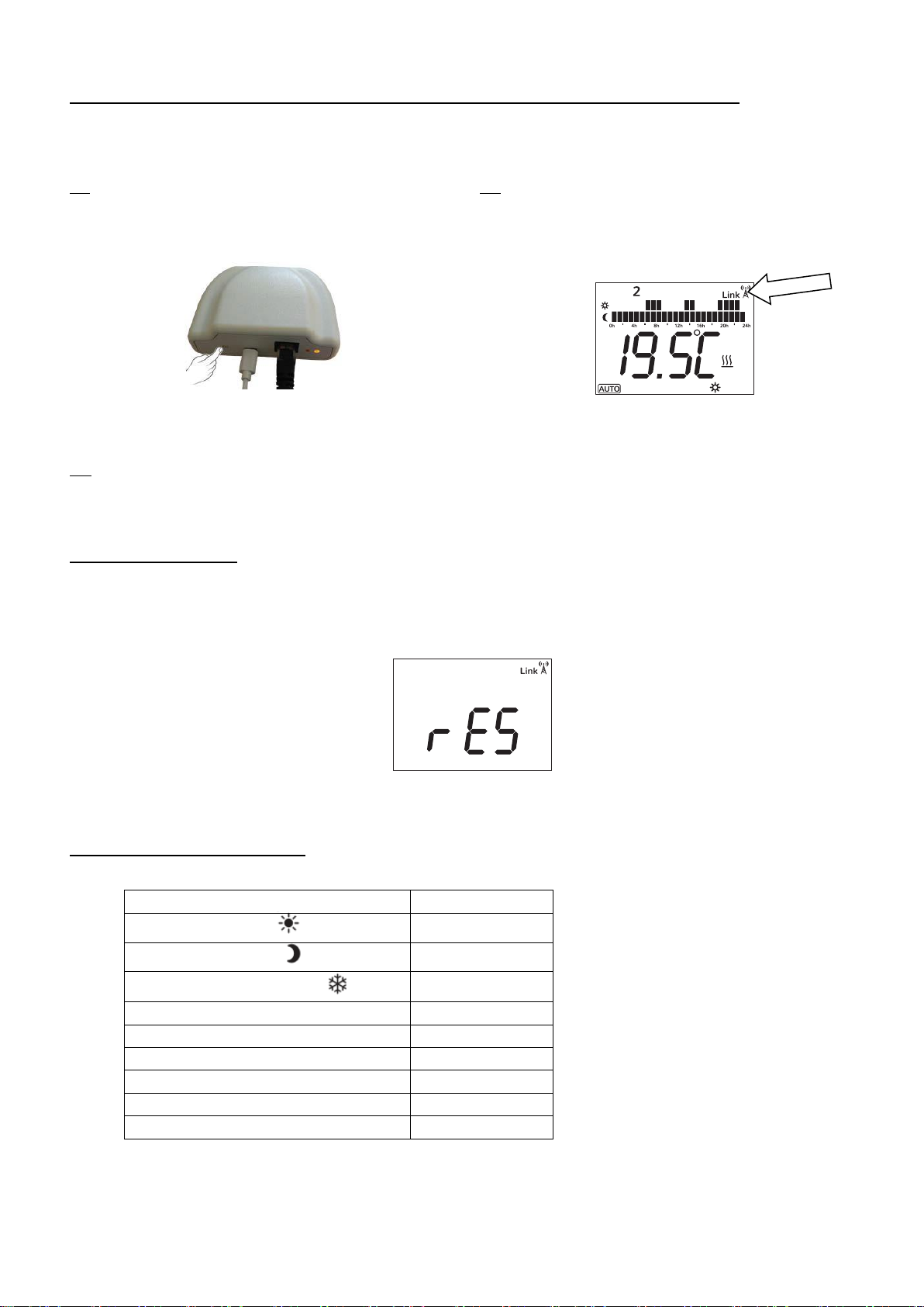
4.1 To associate the unit to the G-Control Hub, the
discovery mode of the hub must be activated. Press the
associate button at the back of the Gateway for 3 seconds. An
orange blinking light every second indicates association mode.
4.2 With the hub in discovery mode, press the Ok/Mode
button on the heater for 3 seconds until the Link symbol is
shown.
You can now control and adjust the programming and temperatures on the heater via the Gabarron-Elnur app.
4.3 To disassociate the unit, a reset of the unit must be realized. See “5. UNIT RESET”. When the heater is reset, it will
remove the programming and revert back to the default settings and also disassociate from the RF network and G-Control Hub.
5.- UNIT RESET
The heater reset removes the programming and disassociates the device from the RF network if the unit was associated with a
G-Control Hub. Default values are established. To reset the unit, hold the OK/Mode and Config/Prog buttons simultaneously
for 10 seconds, the display will show the following to indicate the heater has been reset.
To confirm the reset of the unit, press OK/Mode button, to cancel it any other button can be pressed.
6.- DEFAULT VALUES
Operation mode
OFF
Comfort temperature
19ºC
Economic temperature
17ºC
Frost protection temperature
5ºC
Ambient sensor Offset
0ºC
RF associated
No
Temperature Unit
ºC
Open Window detection
Disabled
Control mode
PID
Default Programming in AUTO Mode
Economic 24h*7
Page 9
9
7.- CLEANING AND MAINTENANCE
The radiators do not precise any special maintenance providing thermal comfort during large periods. Clean dust with a dry,
soft cloth only when the unit is disconnected and cold.
Do not use solvents or abrasive products for cleaning.
After the heating season disconnect the radiator with the switch located on the back surface of the radiator.
This thermal radiator has been manufactured under an assured quality system using environment friendly processes.
Please take the heaters to a clean point once their useful life is finished, in order to recycle their materials in the right way.
8.- TROUBLESHOOTING
The radiator does not heat.
Check the heater or the air inlets are not covered.
The room does not reach the required
temperature.
Check the selected temperature is in accordance with the desired
temperature. Maybe the room needs more heating power.
“OC”, “SC” message is displayed.
Sensor wrong connection. Contact the after sales service.
“Err1”, “Err2”, “Err3”, “Err4” message
is displayed
Contact the after sales service.
Time settings are lost.
There was electric supply shortage or the unit has been disconnected by the
main switch.
The keyboard does not respond.
If the Lock message is displayed, the thermal radiator keyboard is locked.
Hold “+” and “-” buttons simultaneously for 3 seconds to unlock the
keyboard.
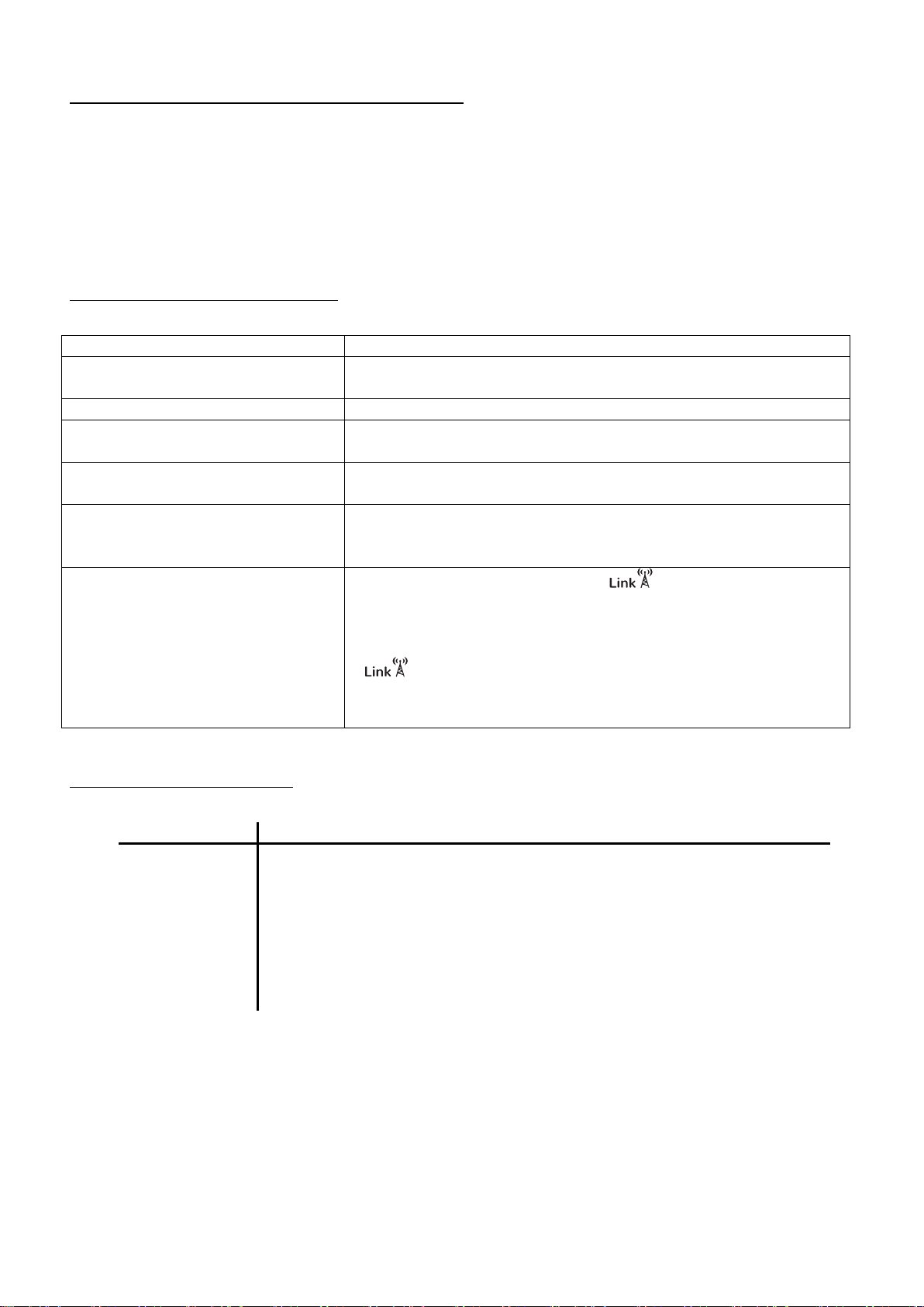
The radiator does not communicate with
the G Control Hub.
Check the unit is associated, the symbol must be shown on the
display LCD.
For distances greater than 30 metros and 2-3 walls, associate first the closest
unit because of each unit can work as repeater.
If symbol is blinking, check the G Control Hub connexion to the
network, and if any other device in the RF Net that could be working as
repeater has been removed.
9.- SPECIFICATIONS
Models
DIL4GC
DIL6GC
DIL8GC
DIL10GC
DIL12GC
DIL14GC
Elements
4 6 8
10
12
14
Length (cm)
43.5
59.5
75.5
91.5
107.5
122
Width (cm)
10 cm plus 2 cm clearance
Height (cm)
58
Weight (kg)
8
11
14
17
20
23
Voltage
220 – 240 V~
Isolation
Class I
Power (W)
500
750
1000
1250
1500
2000
All models are equipped with control trough G-Control Hub connected to the network.
Page 10
10
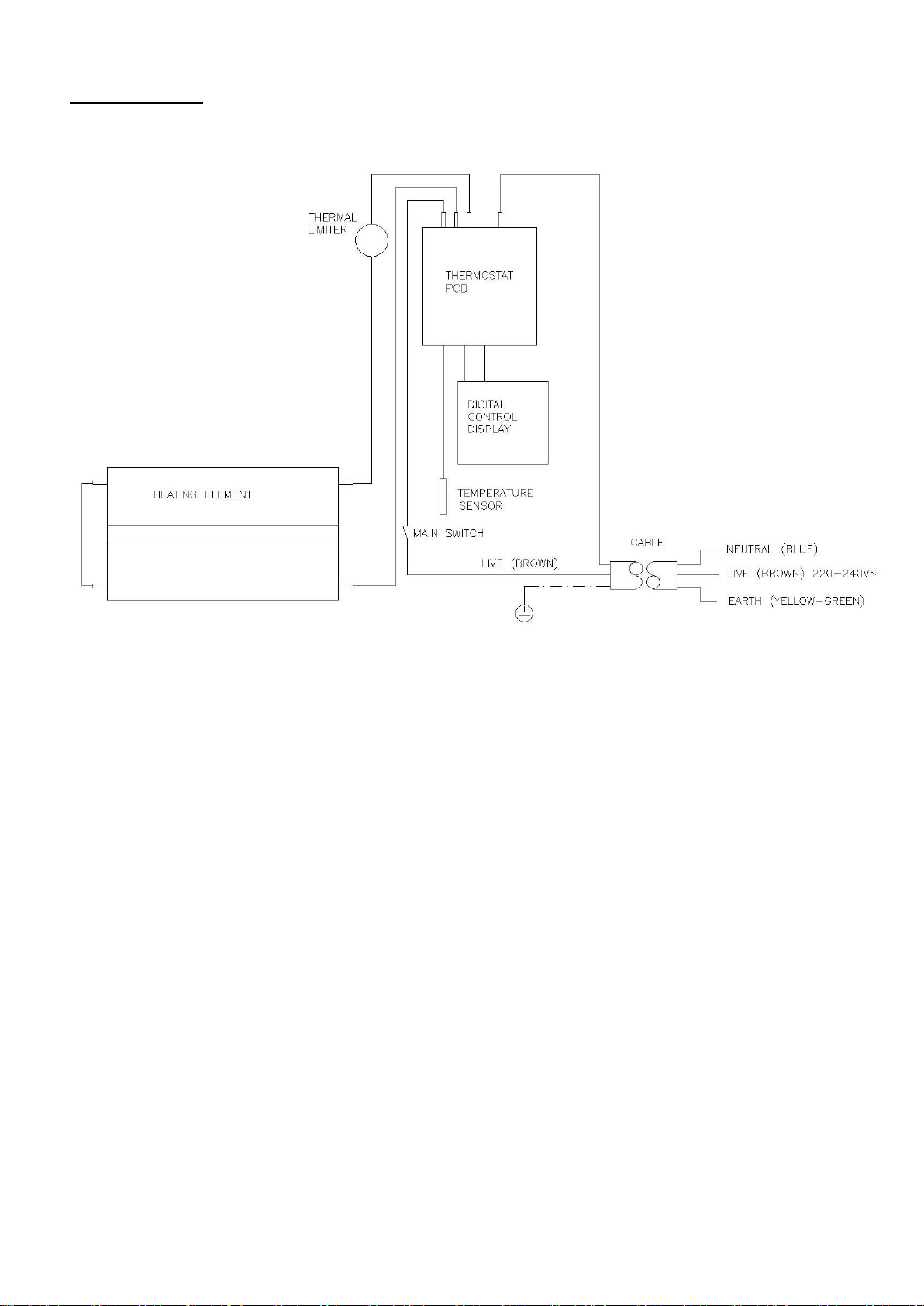
10.- WIRING
Page 11

11
Notes
Page 12
EN: WARNING: In order to avoid overheating do not cover the heater.
Supplier:
ELNUR UK Ltd.
Unit I, Brown Street North
Leigh, Lancashire. WN7 1 BU
Telephone +44(0)1942 670119
www.elnur.co.uk
Manufactured by:
ELNUR S.A.
Travesía de Villa Esther, 11
28110 Algete - Madrid
Telephone +34 91 628 1440
As a part of the policy of continuous product improvement, Elnur s.a reserves the right to alter specifications without notice.
46102242 R3
The symbol on the product or in its packaging indicates that this product may not be treated as household
waste. Instead it shall be handed over to the applicable collection point for the recycling of electrical and
electronic equipment. By ensuring this product is disposed of correctly, you will help prevent potential
negative consequences for the environment and human health, which could otherwise be caused by
inappropriate waste handling of this product. For more detailed information about recycling of this
product, please contact your local city office, your household waste disposal service or the shop where
you purchased the product. These instructions are only valid in the EU member states.
 Loading...