

Page 1
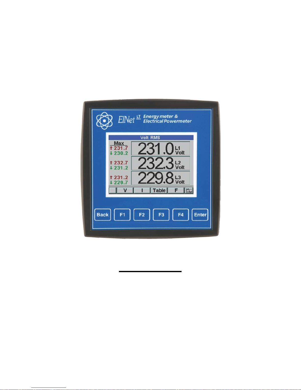
Installation & Operation Manual
ELNet LT
Electrical Measurements & Power Quality
Rev. 1.9
Page 2

2
Table of Contents
CHAPTER 1 ─ INTRODUCTION .......................................5
1.1 — About the ELNet LT Energy Powermeter ........ 5
1.2 — How to use this manual ......................................... 6
1.3 — Safety Information ................................................ 7
1.4 — Warranty ................................................................ 8
1.5 — Your comments are welcome ...............................10
1.6 — Disclaimer ............................................................. 11
CHAPTER 2 — INSTALLATION ...................................... 12
2.1 — Contents of packaging .........................................12
2.2 — Mechanical mounting ..........................................14
2.3 — Wiring Schematics ...............................................16
2.4 — Rear Panel Connections .......................................25
2.5 — Digital Outputs and Inputs. .................................30
2.6 — Manufacturing Data. ...........................................31
CHAPTER 3 — USING ELNet LT POWERMETER .... 32
3.1 — Front Panel ...........................................................32
3.2 — Control Buttons ....................................................33
3.3 — Lock Utility ...........................................................34
CHAPTER 4 — NECESSARY ELNet LT SETTINGS ... 35
4.1 — Settings for Current/Voltage Transformer .........37
4.2 — Electrical Connection Check ...............................38
4.3 — Change language ..................................................42
4.4 — Time Settings ........................................................42
4.5 — Date Settings .........................................................43
4.6 — Setting energy pulse out .......................................44
4.7 — Delta/star Electrical network definition .............45
Page 3

3
CHAPTER 5 — FRONT PANEL DISPLAYS ..............47
5.1 — Current Voltage & Frequency .............................47
5.2 — Reset I , V , F Peak values ..................................49
5.3 — Power Display .......................................................51
5.3.1 — Real time power display ................................ 51
5.3.2 —Reset power peak values ................................. 53
5.3.3 — Power Demand ............................................... 53
5.4 — Power Quality .......................................................54
5.4.1 — Wave Form Display ........................................ 55
5.4.2 — Harmonics Analyzer & THD ......................... 56
5.4.3 — Alarm Setup .................................................... 57
5.5 — Energy Metering ..................................................58
5.5.1 — Main Energy Meter........................................ 59
5.5.2 — 2nd. Energy meter .......................................... 60
5.5.3 — T.O.U Energy .................................................. 61
5.5.4 — Periodic Energy meter ................................... 62
CHAPTER 6 — COMMUNICATION ....................... 63
6.1 — MODBUS Framing ..............................................63
6.1.1— RTU Transmission Mode ................................ 63
6.1.2 — The RTU Frame Format ................................ 64
6.1.3 — Address Field .................................................. 65
6.1.4 — Function Field ................................................ 65
6.1.5 — Data Field ....................................................... 66
6.1.6 — Check Field ..................................................... 66
Page 4

4
6.2 — Registers for ELNet LT Powermeter ............... 67
6.2.1 — Registers addresess ....................................... 68
6.3 — Communication Connections ..............................69
6.4 — Communication Settings ......................................69
6.4.1 — Communication Address ............................... 70
6.4.2 — Baud Rate ....................................................... 70
6.4.3 — Parity............................................................... 70
6.5 — Communication Set Up ........................................71
6.5.1 — Set up Serial Communications .........................71
6.5.2 — Set up Ethernet Communications ....................72
6.6 — Communication with UniArt Software ..............73
CHAPTER 7 — Specifications ........................................... 75
7.1 — Measurement & Display ......................................76
Index .................................................................................... 78
Appendix A — Installation & Configuration Check List ... 78
Page 5
5
CHAPTER 1 ─
INTRODUCTION
1.1 — About the ELNet LT Energy Powermeter
Large consumers of electricity e.g. factories, hotels, hospitals,
municipalities, need to know the history of their consumption
and the quality and the values of the power supply. Details such
as Voltage, Current, Power Factor, Hertz, Neutral Current,
Energy consumption can be displayed by the
ELNet LT
Energy & Powermeter.
An additional feature of the Powermeter is the ability to
measure Harmonics. Part of the Electricity Supply Authority’s
bill reflects poor or good Harmonics in the consumer’s system,
therefore it is in his interest to monitor Harmonics and try to
improve it.
The
ELNet LT
Energy & Powermeter is a compact,
multi functional, three-phase Powermeter simple to install and is
especially designed to integrate into Building Management
Systems. It requires no special mounting and is ideally suited
for mounting on the front face of any standard electrical panel.
The Configuration and Setup is menu driven, with password
protection.
Communication with external devices is simple and is based on
standard known protocol.
Each
ELNet LT
Energy & Powermeter is carefully and
meticulously manufactured using quality components and the
latest production methods. Before leaving the factory each
ELNet LT
Energy & Powermeter is calibrated and is
sent to the customer accompanied by the test certificate and
Certificate of Compliance (C.O.C).
Page 6
6
1.2 — How to use this manual
We at CONTROL APPLICATIONS Ltd, envisage this manual
to be used by three types of people, i.e. the Installation
Technician, the Senior Electrical Engineer and the end User.
For this reason this manual is divided into chapters for ease of
reference by each of these different people. There could be a
situation where two of the above mentioned tasks can be
combined, or in a rare instance one person could handle all three
tasks.
CHAPTER 1, Introduction, describes the
ELNet LT
Energy & Powermeter, its potential users, the readings it can
provide and some of its features in brief.
CHAPTER 2, Installation, provides detailed instructions for
unpacking, mechanical mounting, and electrical wiring up
instructions for the Installation Technician.
CHAPTER 3, Using the
ELNet LT
Energy &
Powermeter, describes in detail front Panel, the functions of
the control buttons, and the Lock Utility.
CHAPTER 4, Parameter Configuration & Settings explains in
detail the minimum parameters settings needed by the Senior
Electrical Engineer to set up and configure the
ELNet LT
Energy & Powermeter.
CHAPTER 5, Front Panel Displays, is an easy to follow stepby-step guide to obtain readings, graphs and tables.
Page 7
7
CHAPTER 6, Communications provides details about the
Communication capabilities of the ELNet LT
Energy &
Powermeter
, and how to Set Up.
CHAPTER 7, Specifications, is a detailed list of specifications
of the ELNet LT
Energy & Powermeter
.
APPENDIX A, Installation & Configuration Check List,
provides a Check List to insure no important steps will be
missed during the initial set up.
1.3 — Safety Information
The purpose of this manual is to help you. Please read the
instructions carefully before performing any installation and
note any precautions.
• Ensure that all incoming AC power and
other power sources are turned off before
performing any work on the
ELNet LT
Energy & Power Powermeter. Failure
to do so may result in serious or even fatal
injury and/or equipment damage.
• If the
ELNet LT
Energy &
Powermeter is damaged in any way do
NOT
connect it to any power source.
WARNING!
Page 8
8
• To prevent a potential fire or shock hazard,
never expose the
ELNet LT
Energy &
Powermeter to rain or moisture.
• Keep the surrounding area free of dirt and
clutter especially metal objects. Good
housekeeping pays.
• Inspect the cables periodically for cracks,
kinks or any other signs of wear.
• Keep children away.
• Do not pull the cords.
• Users should stay alert and not approach the
rear of the
ELNet LT
Energy &
Powermeter while tired or under the
influence of alcohol, medicines or any other
chemical substance that would tend to make
a person drowsy.
• Above all use common sense at all times.
1.4 — Warranty
CONTROL APPLICATIONS Ltd provides a 12- Month
warranty against faulty workmanship or components from date
of dispatch under the condition that the product was properly
installed and used.
CONTROL APPLICATIONS Ltd does not accept liability for
any damage that may be caused by natural disasters (such as
floods, fire, earthquake, lightening etc.).
CONTROL APPLICATIONS Ltd does not accept liability for
any damage that may be caused by malfunction of the ELNet
LT
Energy & Powermeter.
Page 9
9
CONTROL APPLICATIONS Ltd will advise the customer on
the proper installation and use of the ELNet LT
Energy &
Powermeter
,
but will not accept any responsibility that the
instrument is suitable for the application for which it was
originally purchased.
This warranty may become void if the Installation, Parameter
Configuration & Setting Instructions are not carried out
according to the instructions set out by CONTROL
APPLICATIONS Ltd.
The
ELNet LT
Energy & Powermeter
has no user
serviceable parts and should be opened and serviced by a duly
qualified authorized representative only. The sensitive
electronics could become damaged if exposed to a static
environment. This action would void the warranty.
This warranty is limited to the repair and/or replacement at
CONTROL APPLICATION Ltd sole discretion of the defective
product during the warranty period. Repaired or replaced
products are warranted for ninety (90) days from the date of
repair or replacement, or for the remainder of the original
product’s warranty period, whichever is longer.
CONTROL APPLICATIONS Ltd is always at your service to
advise the customer on any problem that may be encountered
regarding any installation, operation, parameter & configuration
settings or maintenance.
Page 10
10
1.5 — Your comments are welcome
CONTROL APPLICATIONS Ltd. sincerely thanks you for
choosing our ELNet LT
Energy & Powermeter
.
We are
confident that it will provide you with many years of trouble
free service and give you all the power and energy information
and history that you expected from the instrument when you
bought it.
While every effort was made to keep the information as reliable,
helpful, accurate and up to date as possible, all possible
contingencies cannot be covered. Technical or typographical
errors could occur, and we would be happy to receive any
comments, criticisms or notifications of any such errors from
you, our valued customer.
Address: FENIKS PRO d.o.o.
Zagrebška cesta 90
2000 Maribor
Slovenia
EUROPE
Tel: 02 460 22 58
Fax: 02 460 22 56
Electronic Address: [email protected]
Page 11
11
1.6 — Disclaimer
Information in this User Manual is subject to change without
notice and does not represent a commitment on the part of
CONTROL APPLICATIONS Ltd.
CONTROL APPLICATIONS Ltd supplies this User Manual as
is without warranty of any kind; either expressed or implied,
and reserves the right to make improvements and/or changes in
the manual or the product at any time.
While it is the intention of CONTROL APPLICATIONS Ltd to
supply the customer with accurate and reliable information in
this User Manual, CONTROL APPLICATIONS Ltd assumes no
responsibility for its use, or for any infringement of rights of the
fourth parties which may result from its use.
This User Manual could contain technical or typographical
errors and changes are periodically made to the information
herein; these changes may be incorporated in new editions of
the publication.
Page 12
12
CHAPTER 2 —
INSTALLATION
In this Chapter you will find the information and instructions
that the Installation Technician needs to mount and connect the
ELNet LT
Energy & Power Powermeter
• During operation, hazardous voltages are
present in connecting cables and terminal
blocks.
• Fully qualified personnel must do all work.
Failure to follow this rule may result in
serious or even fatal injury to personnel
and/or damage to equipment.
• Refer to Section 1.3 Safety information
before carrying out any installation.
• Read this manual thoroughly and make sure
you understand the contents before
connecting the ELNet LT
Energy &
Powermeter
to any power source.
WARNING!
Page 13
13
2.1 — Contents of packaging
To unpack the
ELNet LT
Energy & Power Powermeter
The ELNet LT Energy & Powermeter is packed and
shipped in a carton approximately 24.5 cm long X 19 cm wide
X 12 and cm high.
Before opening the package, ensure the area, clean and dry.
Without using any sharp instruments, carefully open the carton
of the ELNet LT Energy & Powermeter.
Please check the contents of the carton, it should contain:
1.
New ELNet LT Energy & Powermeter
.
2. ELNet LT User Manual (This book).
3. Test Certificate and Certificate of Compliance (C.O.C).
4. 2 X two pole connector plugs.
Page 14
14
2.2 — Mechanical mounting
To Mount the
ELNet LT
Energy & Powermeter
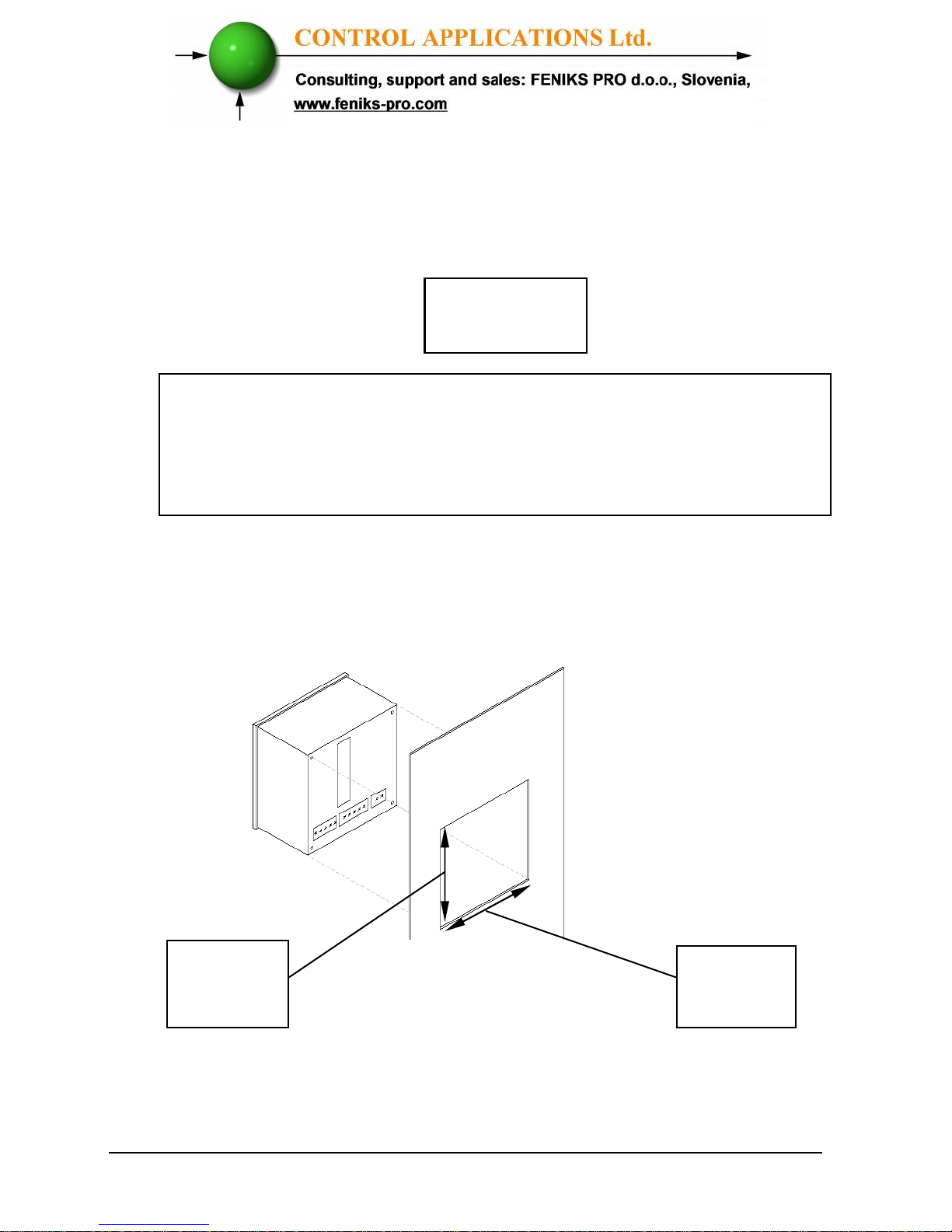
1. Choose a suitable location, and prepare a
rectangular hole according to the dimensions
shown in Figure 2.1
Figure 2.1 Panel Cutout
Do not mount the
ELNet LT
Energy & Powermeter too
close to any main electrical conductors
Allow sufficient space to carry out maintenance to the back of
the
ELNet LT
Energy & Powermeter
NOTE!!
Width
90 mm
Height
90 mm
Page 15
15
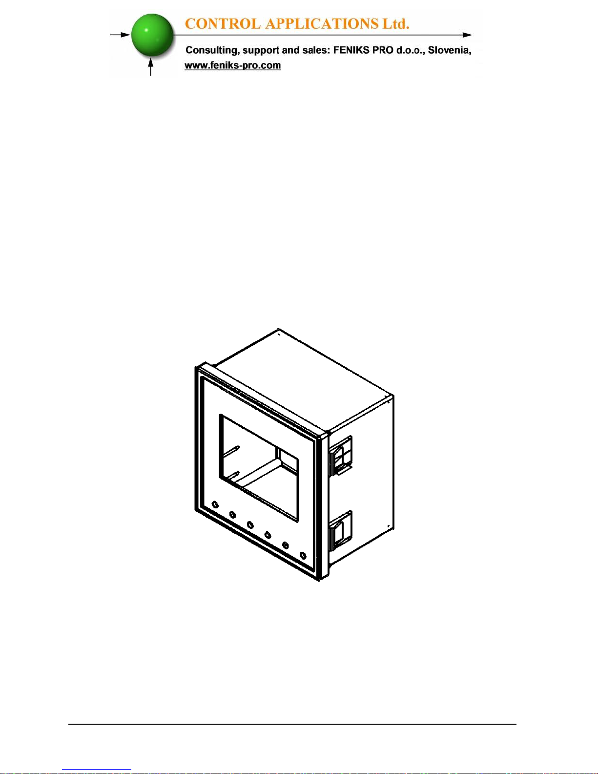
2. Slide the
ELNet LT
Energy &
Powermeter
into the pre-prepared
rectangular hole (ensure it is the right way
up), then push the four mounting clips into
position. Use mild force to ensure the clips
are securely positioned on the outer case of
the ELNet LT
Energy & Powermeter.
3. Ensure the ELNet LT
Energy &
Powermeter
is firmly in place.
Figure 2.2 Mounting Clips
Page 16
16
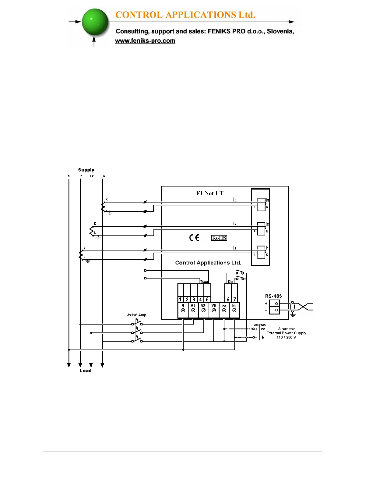
2.3 — Wiring Schematics
To wire up the
ELNet LT
Energy & Powermeter
No galvanic connection with the measurement current wire
(the current wire is passing through the current CT hole).
Figure 2.3 Schematic Wiring Diagram "Star" connection
Page 17
17
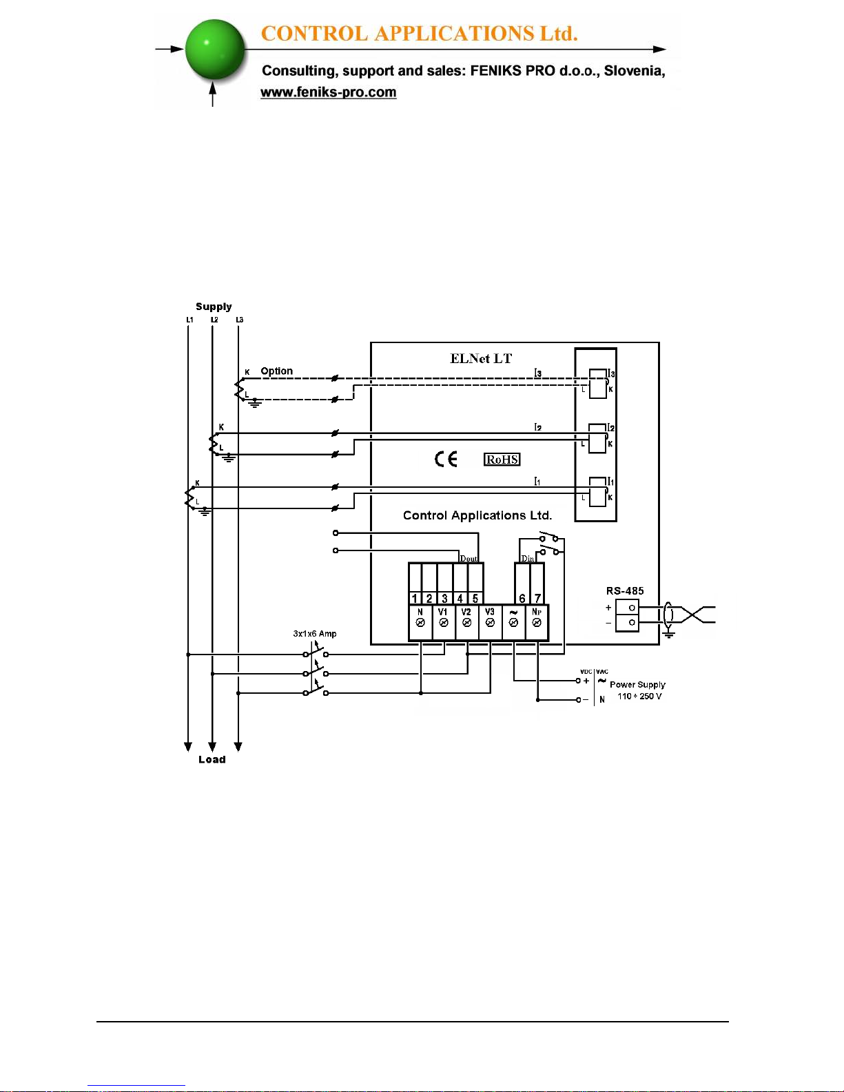
No galvanic connection with the current measurement
wires, the current wires are passing through the current
transformer opening.
Figure 2.4 Schematic Wiring Diagram "Delta" connection
Page 18
18
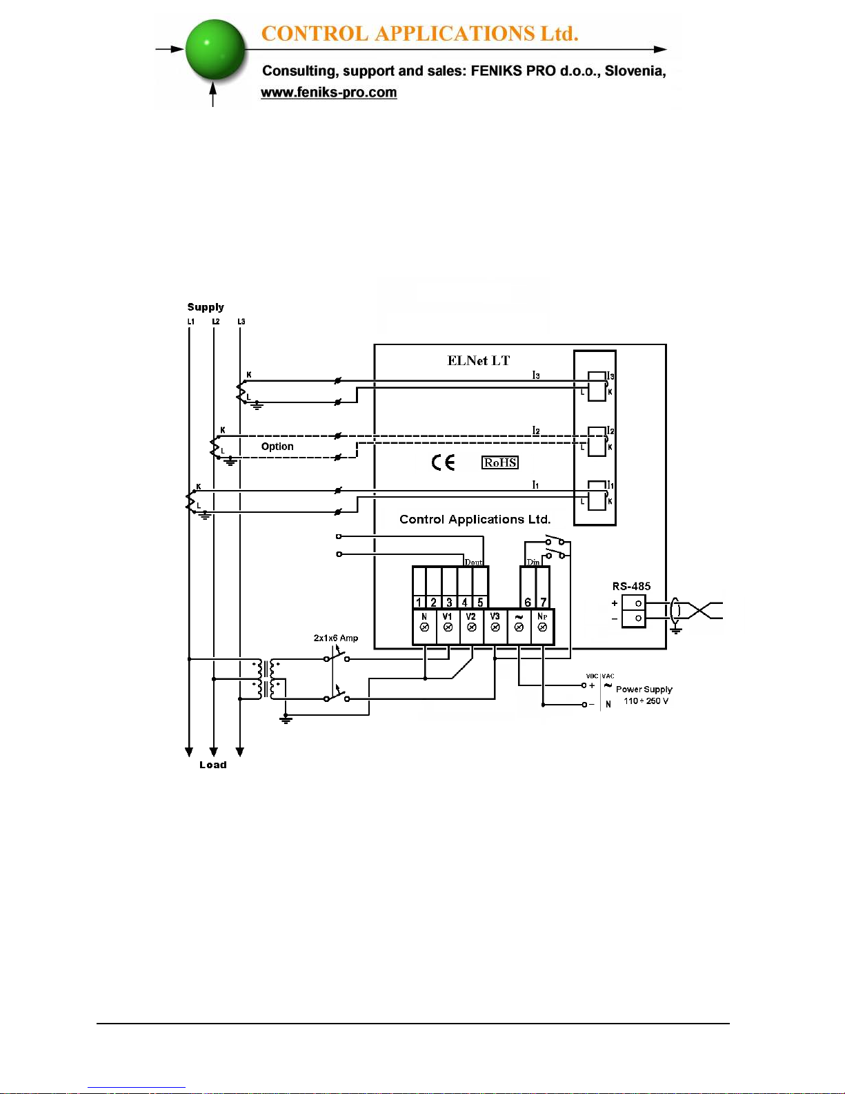
No galvanic connection with the current measurement
wires, the current wires are passing through the current
transformer opening.
Figure 2.5 Schematic Wiring Diagram "Open Delta - 2PTs
2CTs/3CTs" connection
Page 19
19
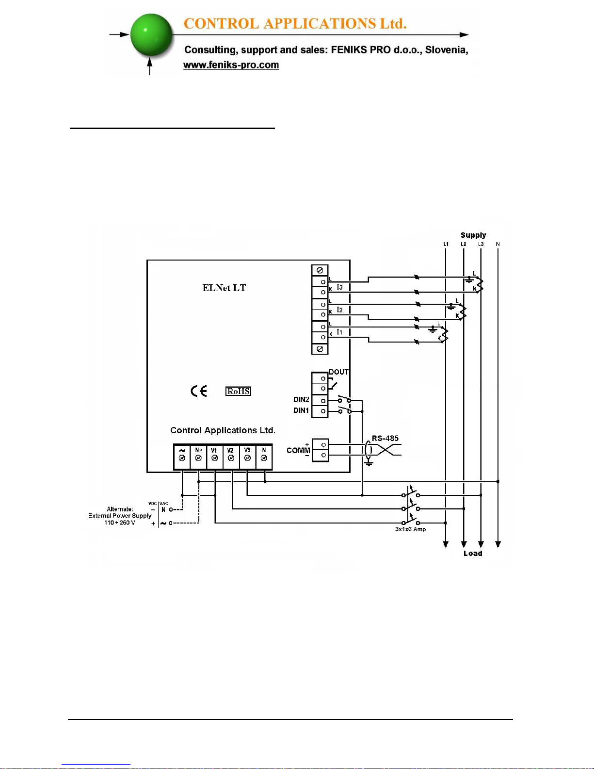
PowermeterEnergy &
LT 2013 ELNet
New model
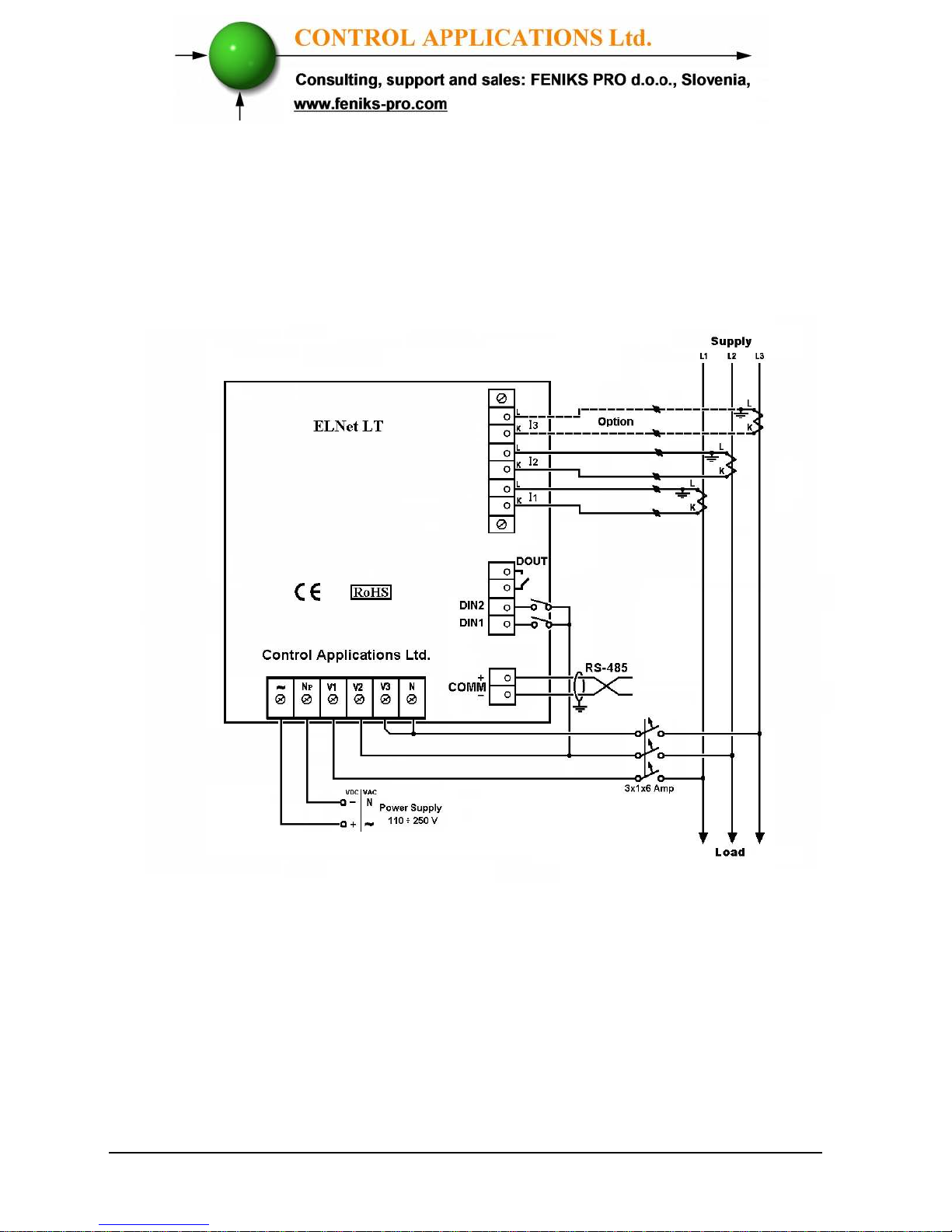
The current measurement wires are connected with screws
to build in standard connectors or optional 60 mm
connectors.
Figure 2.6 Schematic Wiring Diagram "Star" connection
Page 20
20
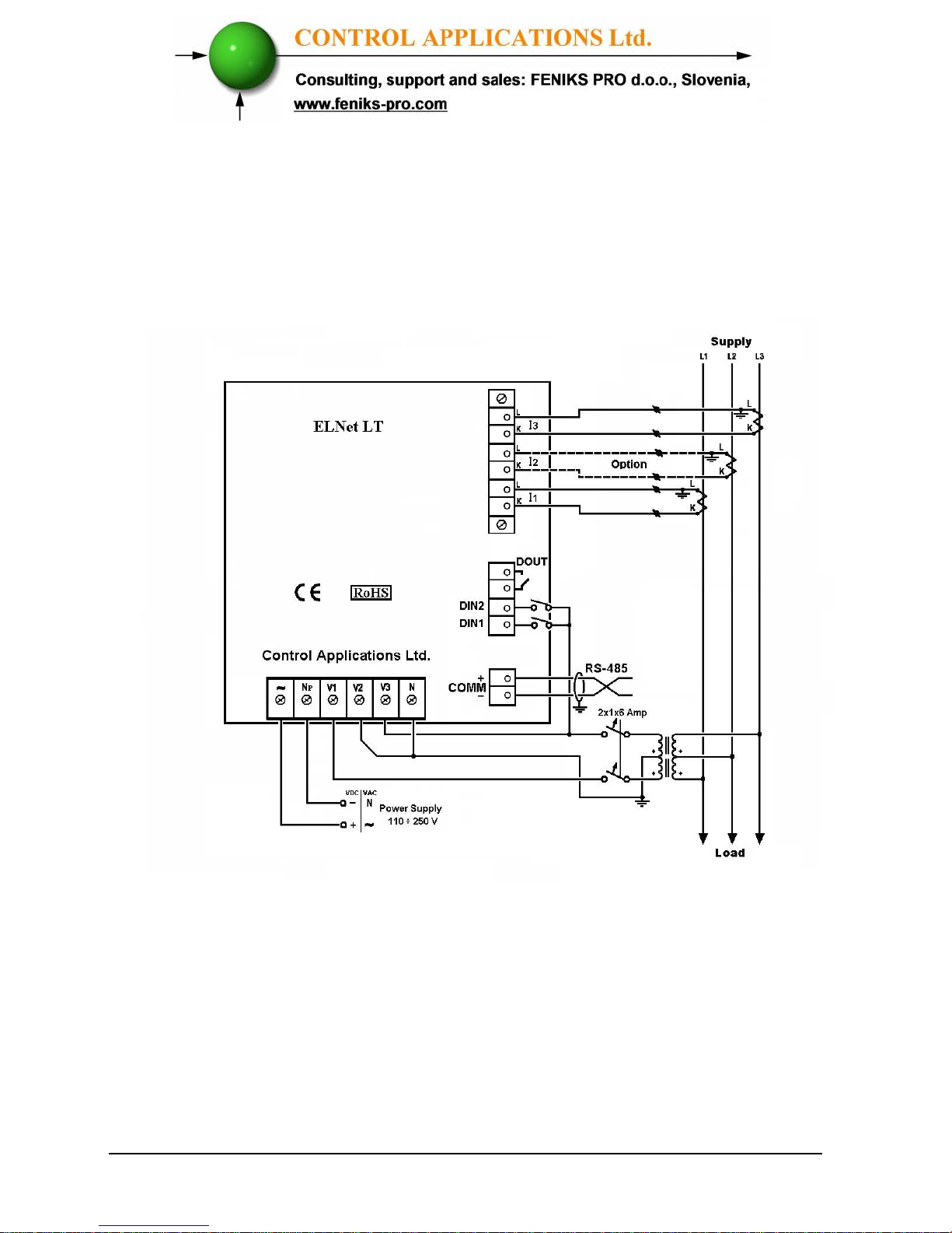
The current measurement wires are connected with screws
to build in standard connectors or optional 60 mm
connectors.
.
Figure 2.7 Schematic Wiring Diagram "Delta" connection
Page 21
21
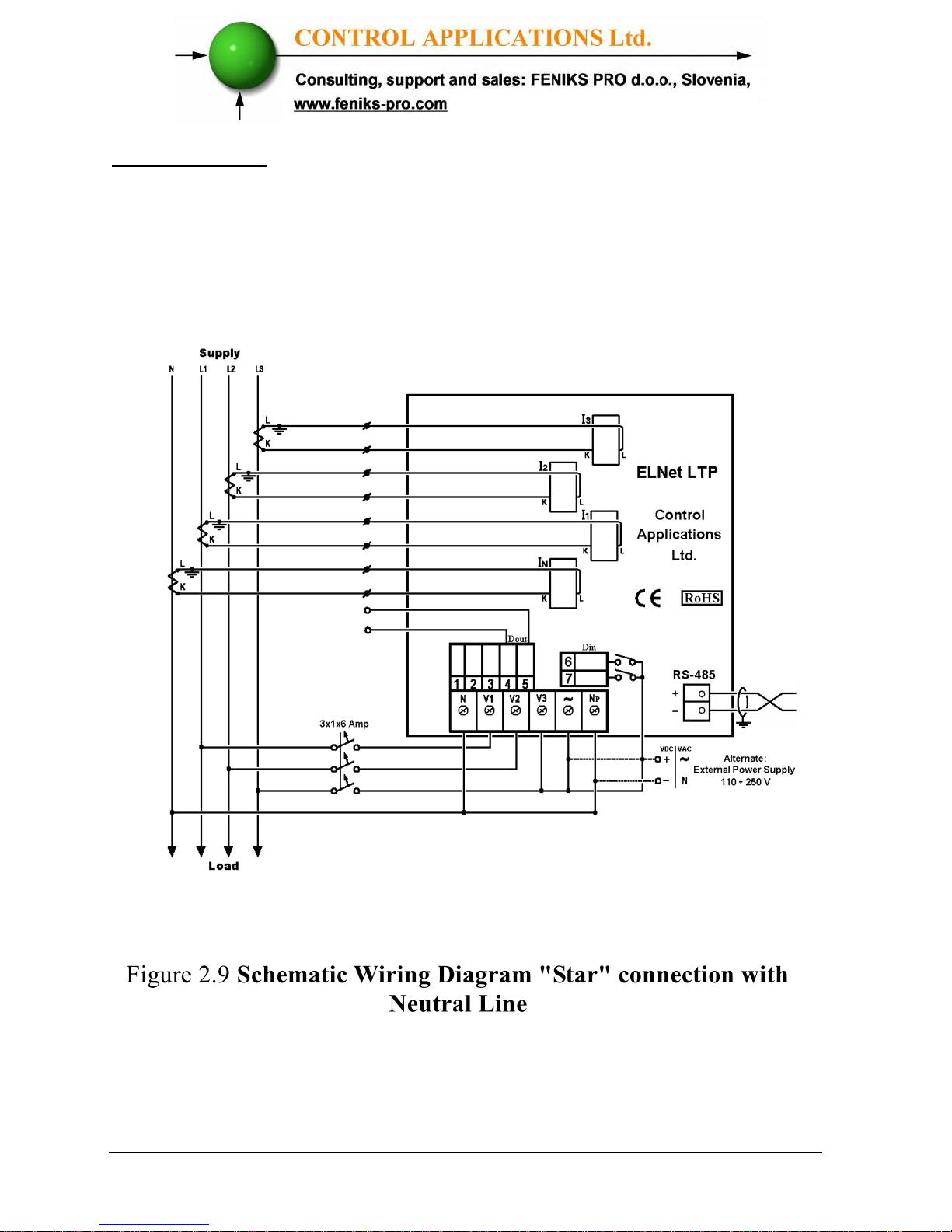
The current measurement wires are connected with screws
to build in standard connectors or optional 60 mm
connectors.
Figure 2.8 Schematic Wiring Diagram "Open Delta - 2PTs
2CTs/3CTs" connection
Page 22
22
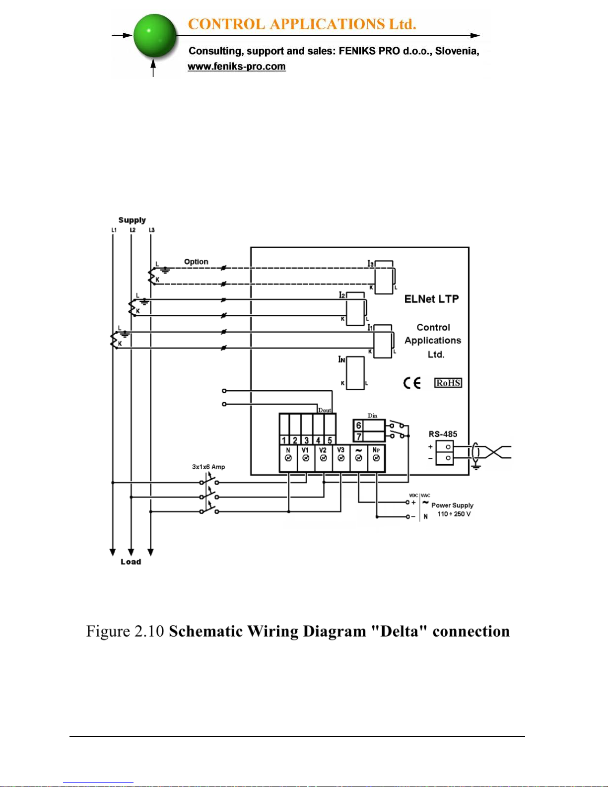
ELNet LTP
Energy & Powermeter
No galvanic connection with the measurement current wire
(the current wire is passing through the current CT hole).
Page 23
23
No galvanic connection with the measurement current wire
(the current wire is passing through the current CT hole).
Page 24
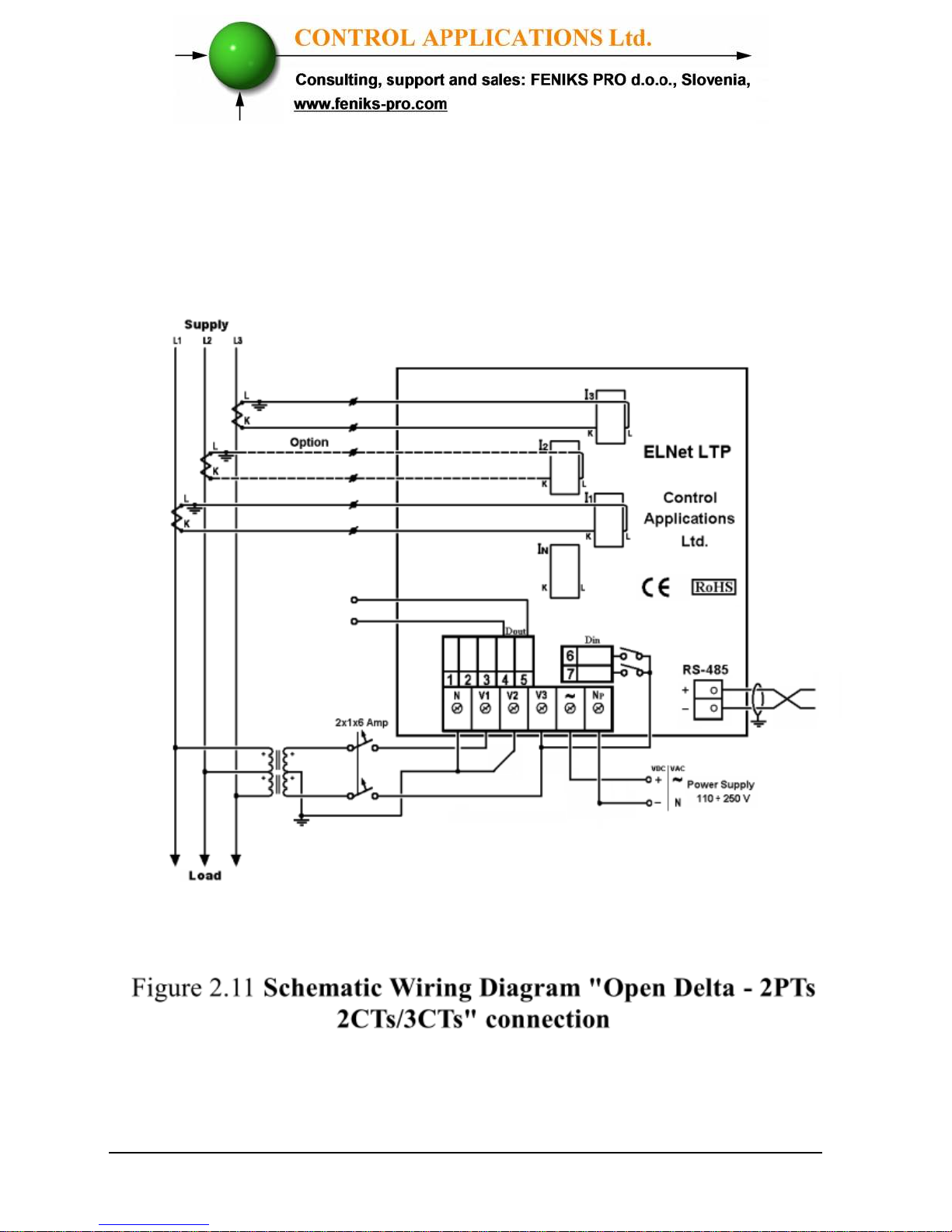
24
No galvanic connection with the measurement current wire
(the current wire is passing through the current CT hole).
Page 25
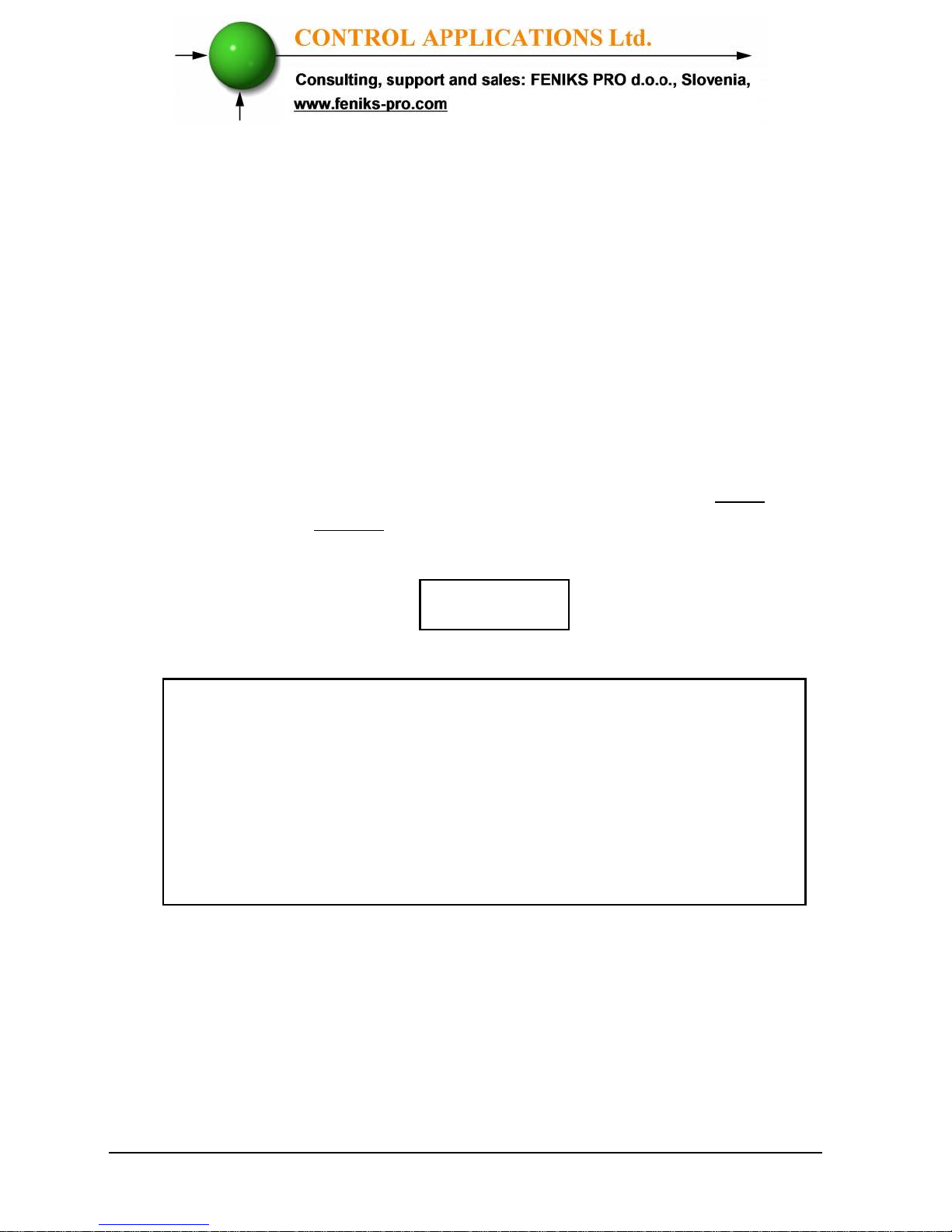
25
2.4 — Rear Panel Connections
Please re-read section 1.3 for safety instructions.
To connect the Rear Panel
All Connections, except those to the CT core of the ELNet LT
Energy & Powermeter
are made via terminal connector plugs
(Voltage input, Power Supply, Communication etc.).
Maximum recommended tightening torque for the connector
screws is 0.5 Nm.
The CT cores of the ELNet LT
Energy & Powermeter
are
located externally on the rear of the instrument and the lead
from the leg of the external Current Transformer must pass
through in the correct direction.
NOTE!
Ensure all the connections to the leads of the current
transformer wiring are secure and there is no mechanical
strain on the wire. The cross section of the leads to the
current transformer must be compatible to the power of the
current transformer. We recommend a power transformer
with at least 3VA and the length of the wiring of the
transformer no longer than 3m.
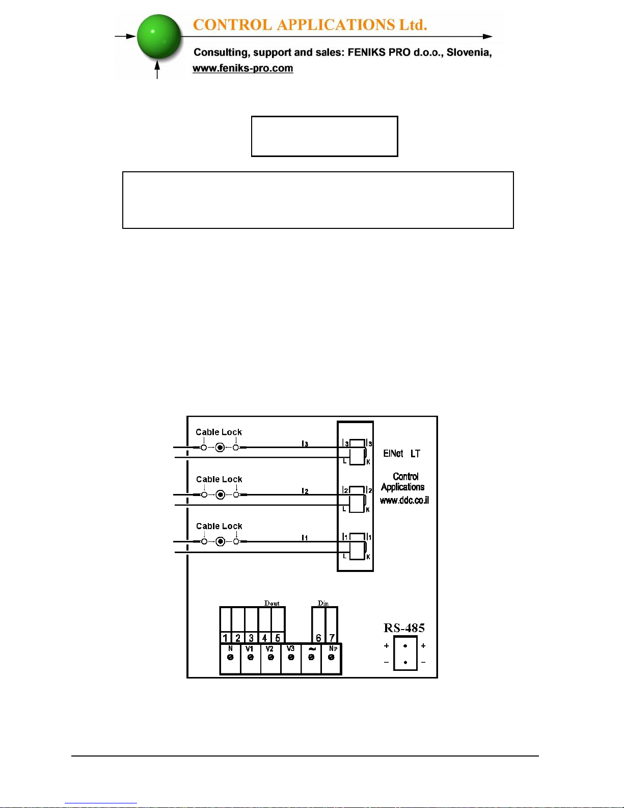
Insert the leads from side “L” of the external Current
Transformers to the ELNET current transformers side “L” and
from side “K” of the ELNET current transformers back to side
“K” of the external transformers.
Page 26
26
WARNING!
WARNING
Never allow an open circuit between the two Current
Transformer leads.
Repeat the procedure for Line 2 and Line 3.
Connect the rest of the connections to the ELNet LT
Energy
& Powermeter
by means of terminal connector plugs.
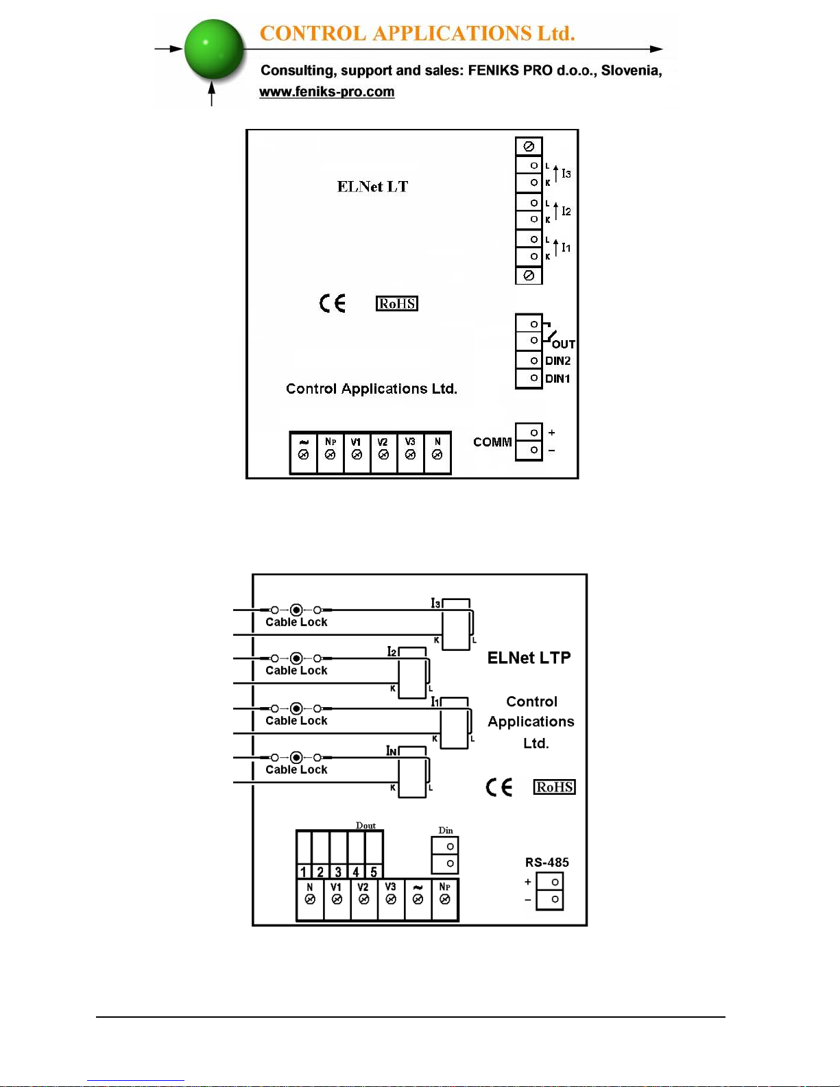
The Rear Panel (See Figure 2.4) has all connections printed and
is simple to follow. (See table 2-1 for connections)
Figure 2.12 Rear Panel
Page 27
27
Figure 2.13 New Model Rear Panel
Figure 2.14 LTP Model Rear Panel
Page 28
28
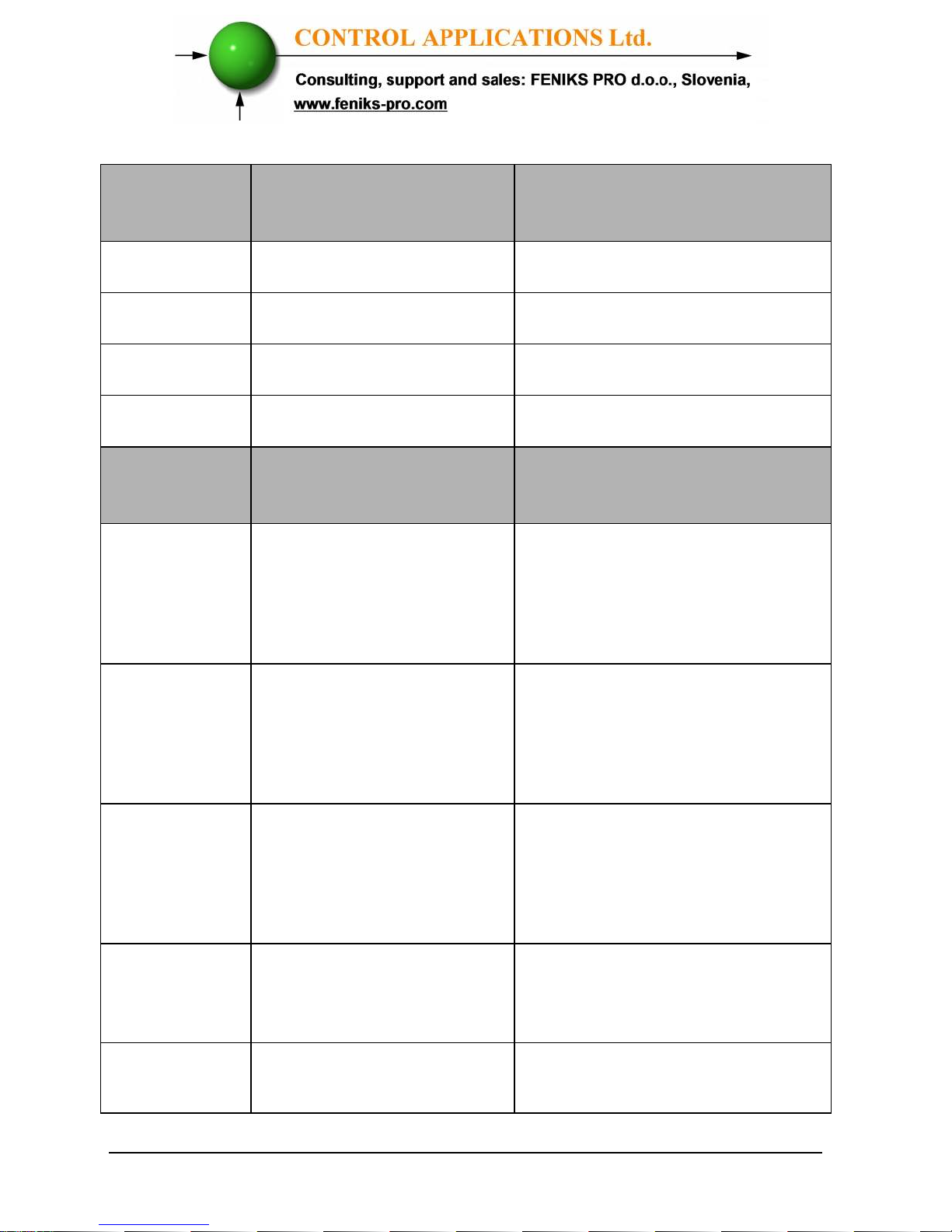
Pin
Designation
Description Remarks
V
1
Line1 Supplied Voltage Through a 6Amp fuse
V
2
Line2 Supplied Voltage Through a 6Amp fuse
V
3
Line3 Supplied Voltage Through a 6Amp fuse
N
Neutral Measurement neutral Line
Pin
Designation
Description Remarks
I
1A
From Current
Transformer on Line1
Note the correct direction to
insert the lead.
Will show 0 Amp if no
voltage connected.
I
2A
From Current
Transformer on Line2
Note the correct direction to
insert the lead
Will show 0 Amp if no
voltage connected.
I
3A
From Current
Transformer on Line3
Note the correct direction to
insert the lead
Will show 0 Amp if no
voltage connected.
~
Power Supply 110 –
260 VAC
Or 110-260 VDC, external
power supply or bridged
from phase measurement
Np
Neutral Neutral of external power
supply
Page 29
29
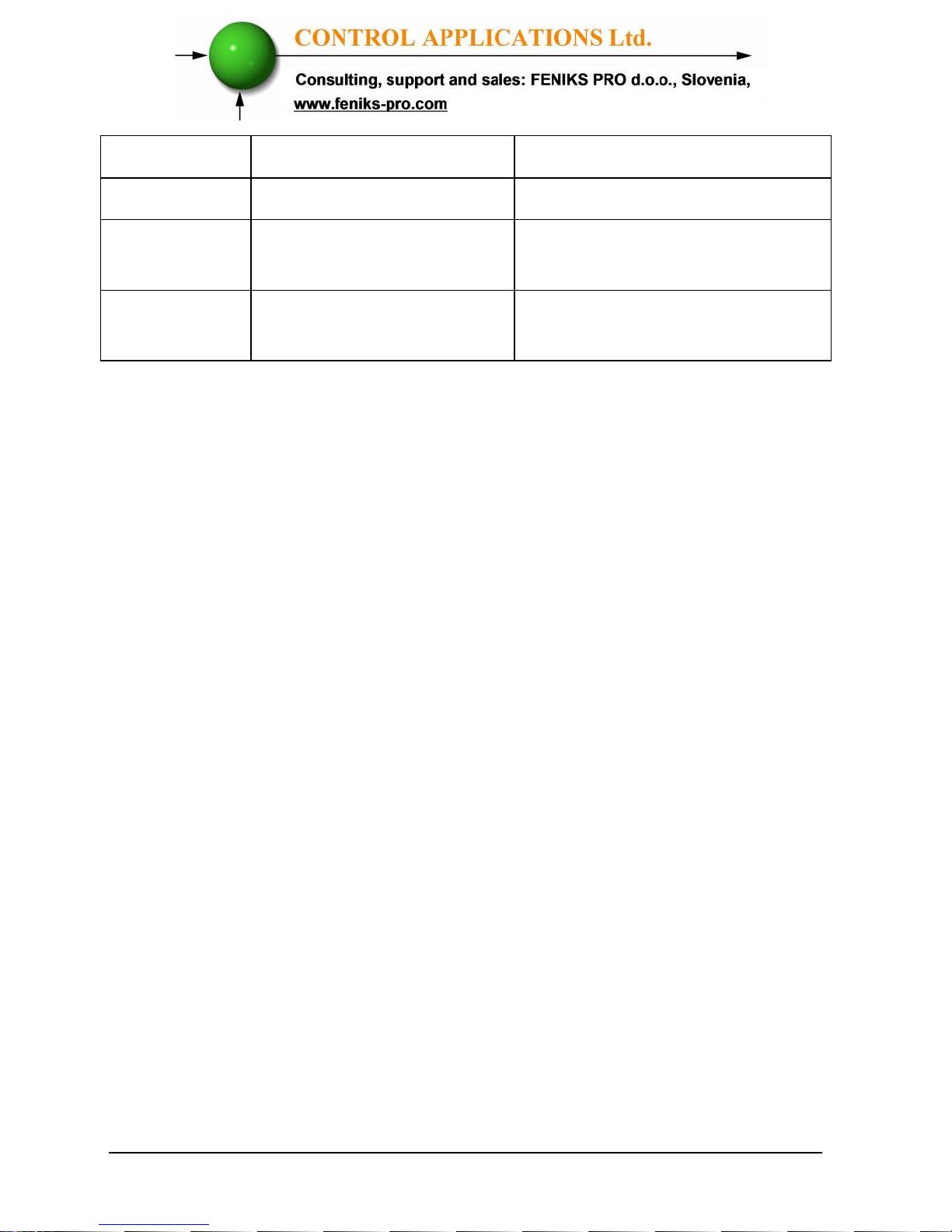
RS485 - RS485 Comm. (-) Line
RS485 + RS485 Comm. (+) Line
Digital Out Dry contact between
pin 4 and 5
Max. Load 150 mA
Digital
Input
Digital inputs 6 and 7
for monitoring
On = 220VAC
Table 2.1 Rear Panel connections
Page 30

30
2.5 — Digital Outputs and Inputs.
ELNet LT
Energy & Powermeter has as default 1 Digital Output and
2 Digital Input connections at its back side (additional IO can be
implemented by using additional external modules).
Digital Output:
The Digital Output of the LT can be used to transmit pulses of energy to
external BMS controller (chapter 4.6) or to close contact upon alarm
(chapter 5.4.3) which can be defined in the LT (cannot be used for both
simultaneously). The Digital Out closes contact of SSR between pins 4 and
5, the maximum load is 150mA.
Digital Inputs:
In order to change the status of the Digital Inputs of the LT a 220 VAC
contact must be provided. The indication voltage should be supplied from
one of the measured phases. The digital inputs can be monitored by
communication and appear at the communication list.
Figure 2.15 Digital In \ Digital Out wiring example
Page 31
31
2.6 — Manufacturing Data.
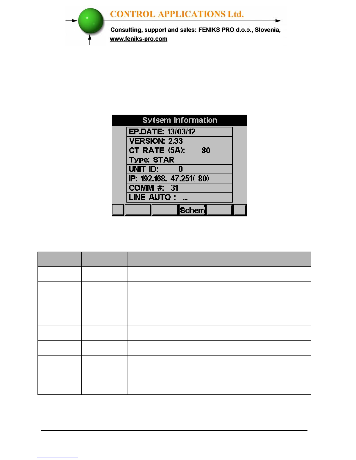
Press F1 on the keyboard for 6 seconds. The following screen will appear.
Figure 2.16 Manufacturing data
Number Screen Description
1 Ep. Date Production date of software operating system
2 Version Bios Revision
3 CT Rate Current transformer ratio
4 Type Hardware type and electrical network connection
5 Unit ID
Unique
identifying number
6 IP Address IP Address ( option)
7 Comm # Communication address of RS485 Modbus
8 Line: Auto \ OFF \ Swap – status of auto correction
mode for K L wiring
Table 2.2 Production Data
Page 32
32
CHAPTER 3 —
USING ELNet LT POWERMETER
In this chapter you will find descriptions and functions of the
front panel and the control buttons and how to use them.
3.1 — Front Panel
To operate the front panel
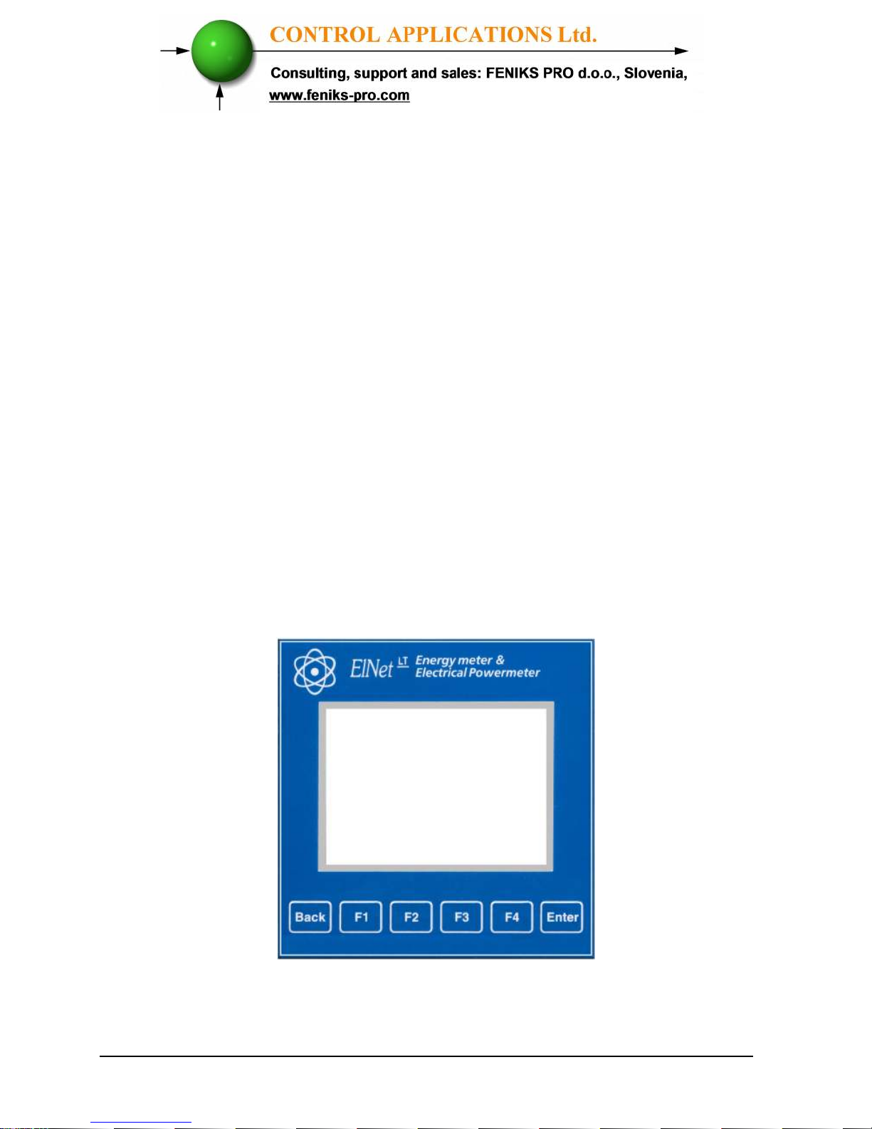
The Front Panel has a graphic screen and 6 operating buttons.
All the readings are shown on a state of the art 320 X 240
resolution graphic screen and are explained in detail in Chapter
5.
The Control Buttons and their functions are fully explained in
Section 3.2.
Figure 3.1 Front Panel
Page 33
33
3.2 — Control Buttons
To operate the Control Buttons on Front Panel
The
ELNet LT
Energy & Powermeter has six Control
Buttons. With these buttons the
User
and
Senior Electrical
Engineer
can achieve all the functions necessary.
The Control Buttons are arranged on a keypad below the display
screen and require slight finger pressure to click.
Button “ENTER” accepts the choice and executes the
commands.
Button “F1”, “F2”, “F3”, “F4” performs the function that the
arrow above is pointing to (e.g. move the cursor), or selects the
prompt that the arrow is pointing to.
Button BACK returns to the previous step or to the Main Menu.
Page 34
34
3.3 — Lock Utility
To lock and unlock the Control Buttons
The Control Buttons can be locked against any unauthorized or
accidental usage.
NOTE!
Only sub menus can be locked. The Lock Utility
does not work on the Main Menu
To lock press “ENTER” for six (6) seconds.
A “Keyboard Locked!” message appears on the screen when any
button is pressed.
To unlock simply press
“ENTER”
for six (6) seconds.
A “Keyboard Unlocked!” message appears on the screen and
normal functions can resume.
In the event of a general power failure, the
ELNet LT
Energy
& Powermeter will return to the screen that was showing before
the power failure occurred.
Page 35
35
CHAPTER 4 —
NECESSARY ELNet LT SETTINGS
In this chapter you will find instructions to set the minimum
settings that are necessary to allow the ELNet LT
Energy &
Powermeter
to function properly.
• The selection, installation and settings of the
Current Transformer are the most vital and
fundamental actions required to ensure the
accuracy of the
ELNet LT
Energy
Powermeter.
• It is essential to know the ratio of the Current
Transformer being installed into the system in
order to set the parameter for the Current
Transformer correctly.
• All three main current Lines MUST have
Current Transformers of the same ratio installed
onto them.
WARNING!
Page 36
36
4.0 — Entering code
The most important setting necessary for the proper
functioning of the
ELNet LT
Energy &
Powermeter is the Current Transformer setting.
The cross section of the leads to the current Transformer
must be compatible to the power of the current
transformer. We recommend a power transformer with at
least 3VA and the length of the wiring of the transformer
no longer than 3m.
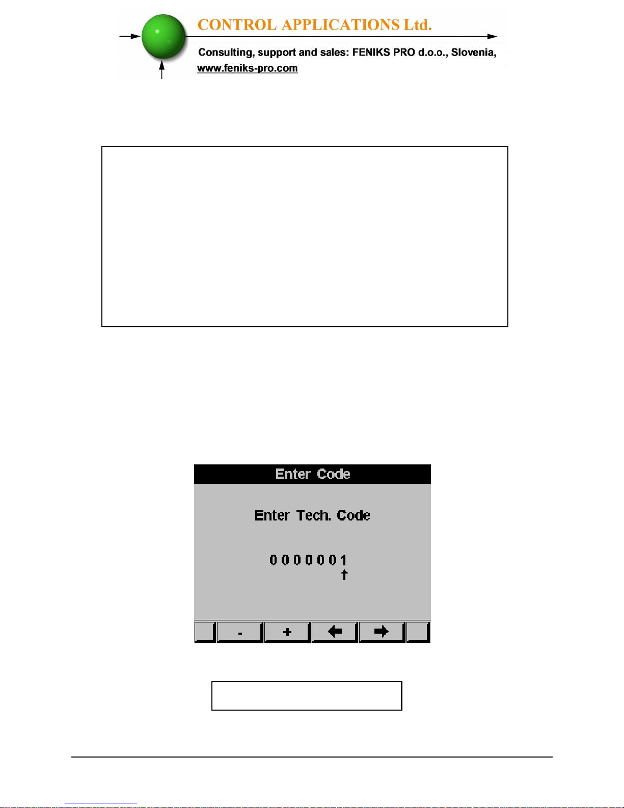
1 From Main Menu scroll to Technical Menu.
2 Click “ENTER”.
The Enter Code screen appears
Figure 4.1 Enter Password
The password is 1.
Page 37
37
3 Use the buttons F3 & F4 to move the cursor, to set the value
use buttons F1 &F2.
4 Click “ENTER”
.
If the incorrect password is inserted into the Password
field, an Error message appears and the password
should be reentered
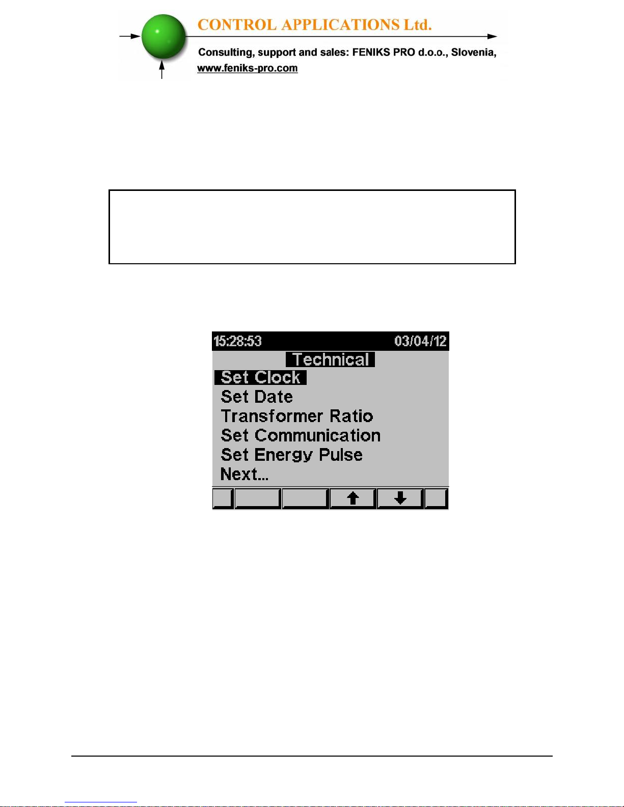
The Technical Menu screen appears
Figure 4.2 Technical Menu
Use the buttons F3 & F4 to move the cursor, selecting "NEXT"
will lead you to more functions that can be set by the
technician.
4.1 — Settings for Current/Voltage Transformer
To set or change settings for Current/Voltage Transformer
See Section 4.0 for instructions to arrive at the Technical Menu
Page 38
38
1 Scroll to Transformers ratio and select current or voltage
transformer ratio to be set.
2 Click “ENTER”.
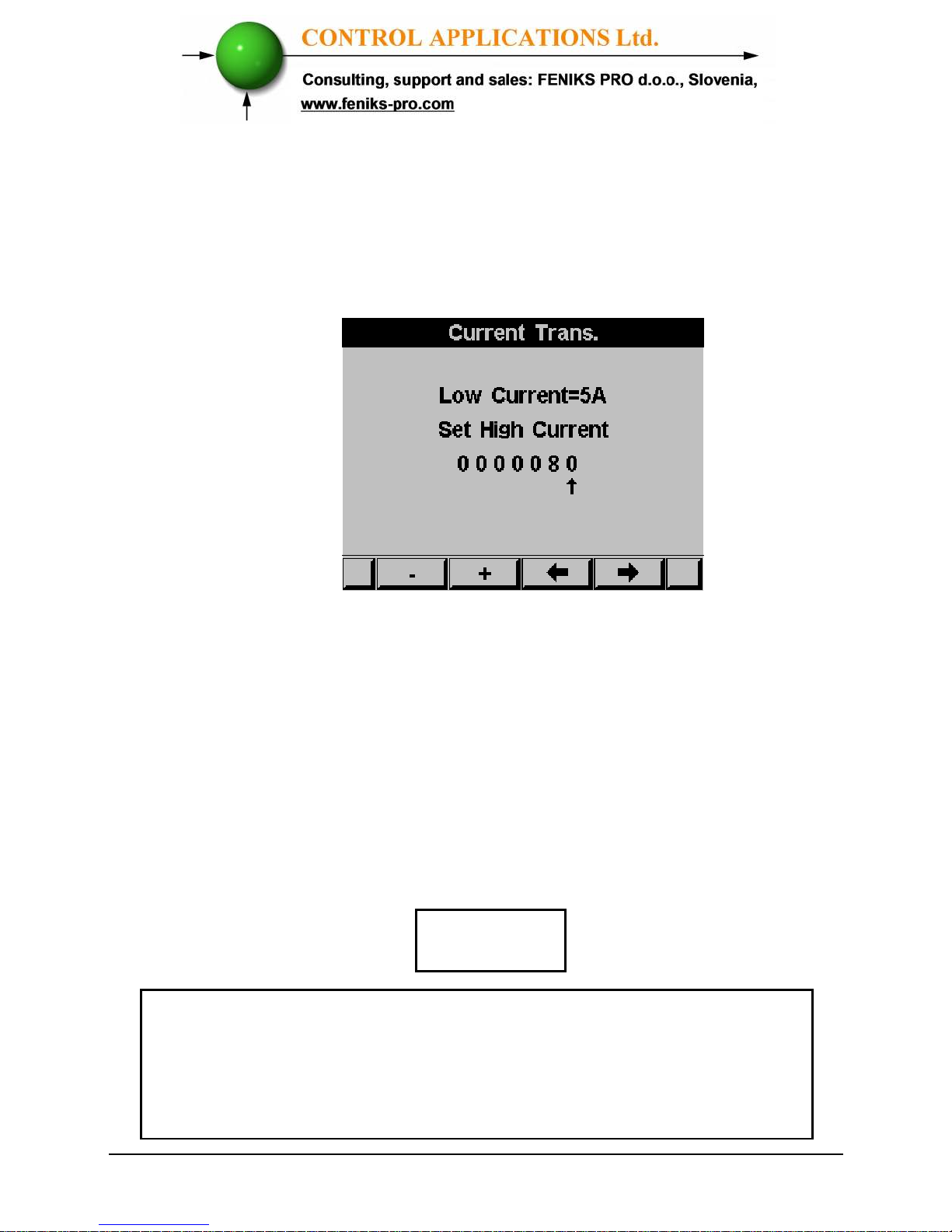
The Current / Voltage Transformer screen appears
Figure 4.3 Current Transformer
The present setting for the Current Transformer is shown.
Use the buttons F3 & F4 to move the cursor, to set the ratio use
buttons F1 &F2.
The method for setting for the Voltage Transformer is the
same.
4.2 — Electrical Connection Check
To avoid any problems arising from incorrect Voltage
Connections or accidental reversal of Current Transformer
Connections, it is necessary to perform a Phase Order Check
before continuing.
NOTE!
Page 39
39
The proper current direction connection ("K" and "L") between
the External CT and the ELNet is very important in case that the
energy direction is monitored and the energy should be logged as
Import (consumed) or Export (produced) modes.
ELNet energy powermeter can auto correct the wrong current
direction wiring (in case the Export energy is not required to be
logged).
As default the device is defined to perform the auto correction. In
order to change these settings and deactivate or activate the auto
correction mode:
1 See Section 4.0 for instructions to arrive at the
Technical Menu
2 From Technical Menu click Next and scroll to
Wiring and press "Enter".
3 Scroll to Current Lines and press "Enter".
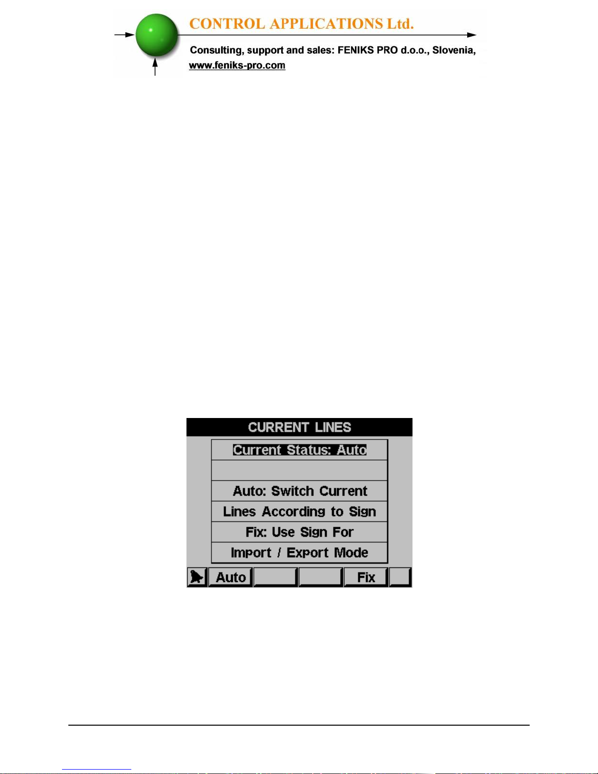
4 The Current Lines screen will appear:
Figure 4.4 Current Lines
5 Click Auto to activate auto correction mode or click
Fix to deactivate (in case the Export energy is
required to be logged).
Page 40
40
To perform Electrical connection Check
1 From Main Menu scroll to Technical.
2 Click
“ENTER”.
The Enter Code screen appears.
3 Enter code: 11
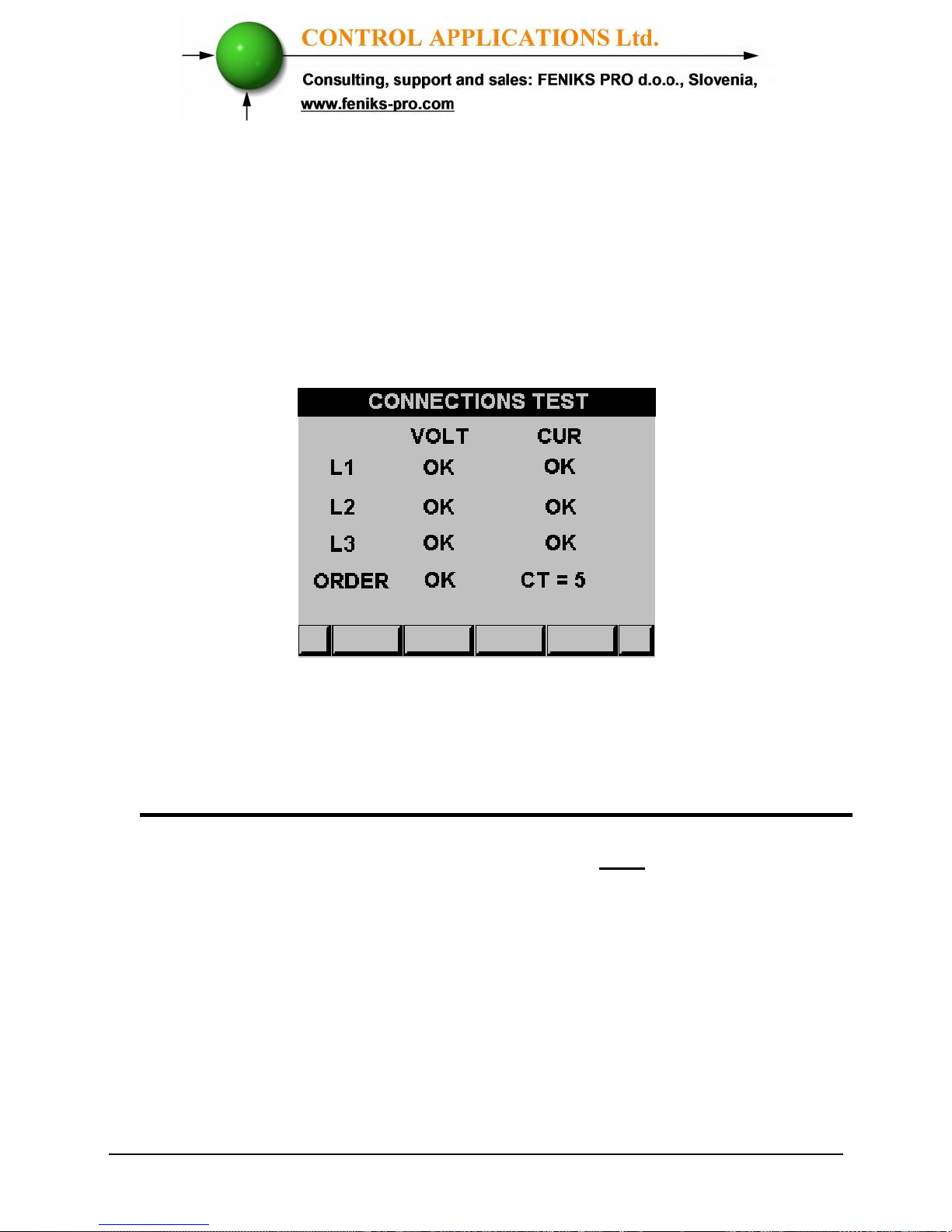
The Connections Test screen appears
Figure 4.5 Connections Test
Very important – very common problem!!!!!
The information above and under is accurate only if there is a phase
coloration between the current and voltage.
The current (I1, I2, I3) and the voltage (V1, V2, V3) should be
connected in this order.
Page 41
41
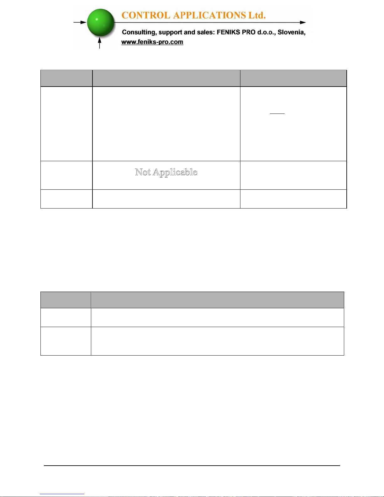
Table 4.1 Voltage and Current Messages
Phase Order Messages
Table 4.2 Phase Order Messages
Message
Voltage Current
OK
Voltage “OK” present on Lines.
If “OK” is not present on 3
Lines, then it is not connected
correctly
Current present in
Lines and synchronized
with Voltage Lines. If
“OK” is not present on
3 Lines, then it is not
connected correctly
OPP
Wired in incorrect
direction
NO
No Voltage
No current
Message
Voltage
OK
Correct Phase Order of Voltage Connections
OPP
Incorrect Phase Order i.e. Line 2 does not follow Line 1
and/or Line 1 does not follow Line3
Page 42
42
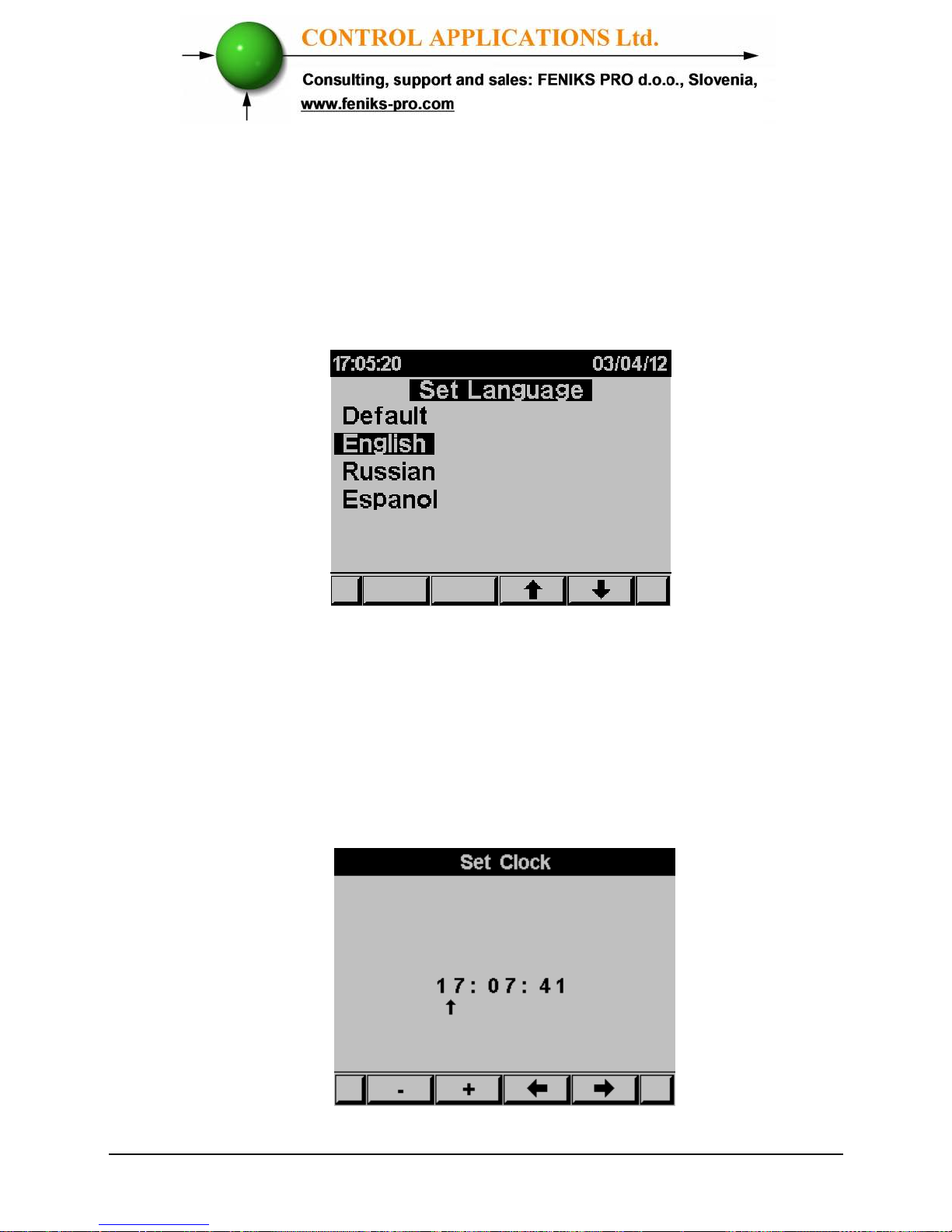
4.3 — Change language
To change language on the display screen
See Section 4.0 for instructions to arrive at the Technical Menu
From Technical Menu scroll to "NEXT" and "LANGUAGE".
1 Click
“ENTER”
.
The Set Language screen appears
Figure 4.6 Set Language
4.4 — Time Settings
To set Time
See Section 4.0 for instructions to arrive at the Technical Menu
From Technical Menu scroll to Set clock.
1. Click
“ENTER”
.
The Set Clock screen appears
Figure 4.7 Set Clock
Page 43
43
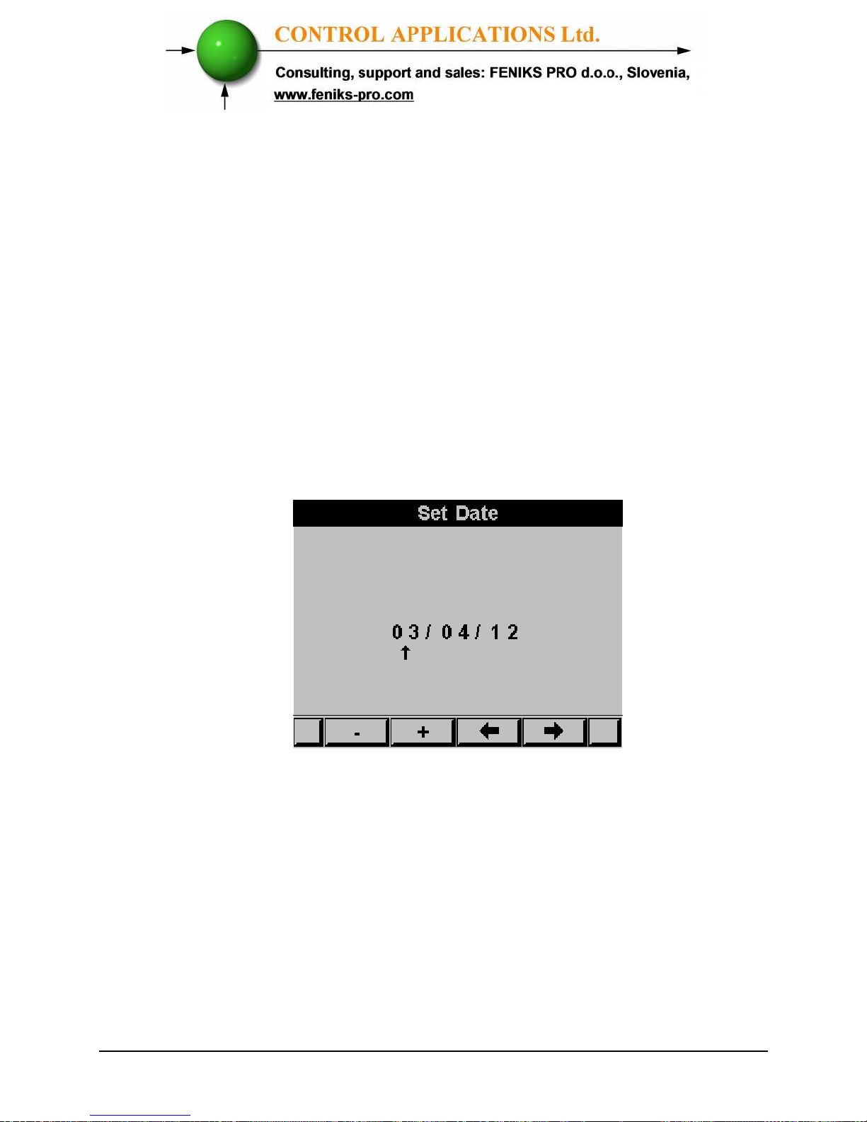
2. Use the buttons F3 & F4 to move the cursor, to set the value
use buttons F1 & F2.
4.5 — Date Settings
To set Date
See Section 4.0 for instructions to arrive at the Technical Menu.
From Technical Menu scroll to Set Date
1 Click “ENTER”
The Set Date screen appears
Figure 4.8 Set Date
Use the buttons F3 & F4 to move the cursor, to set the value use
buttons F1 & F2.
The Date Format is DD/MM/YY
Day/Month/Year
Page 44
44
4.6 — Setting energy pulse out
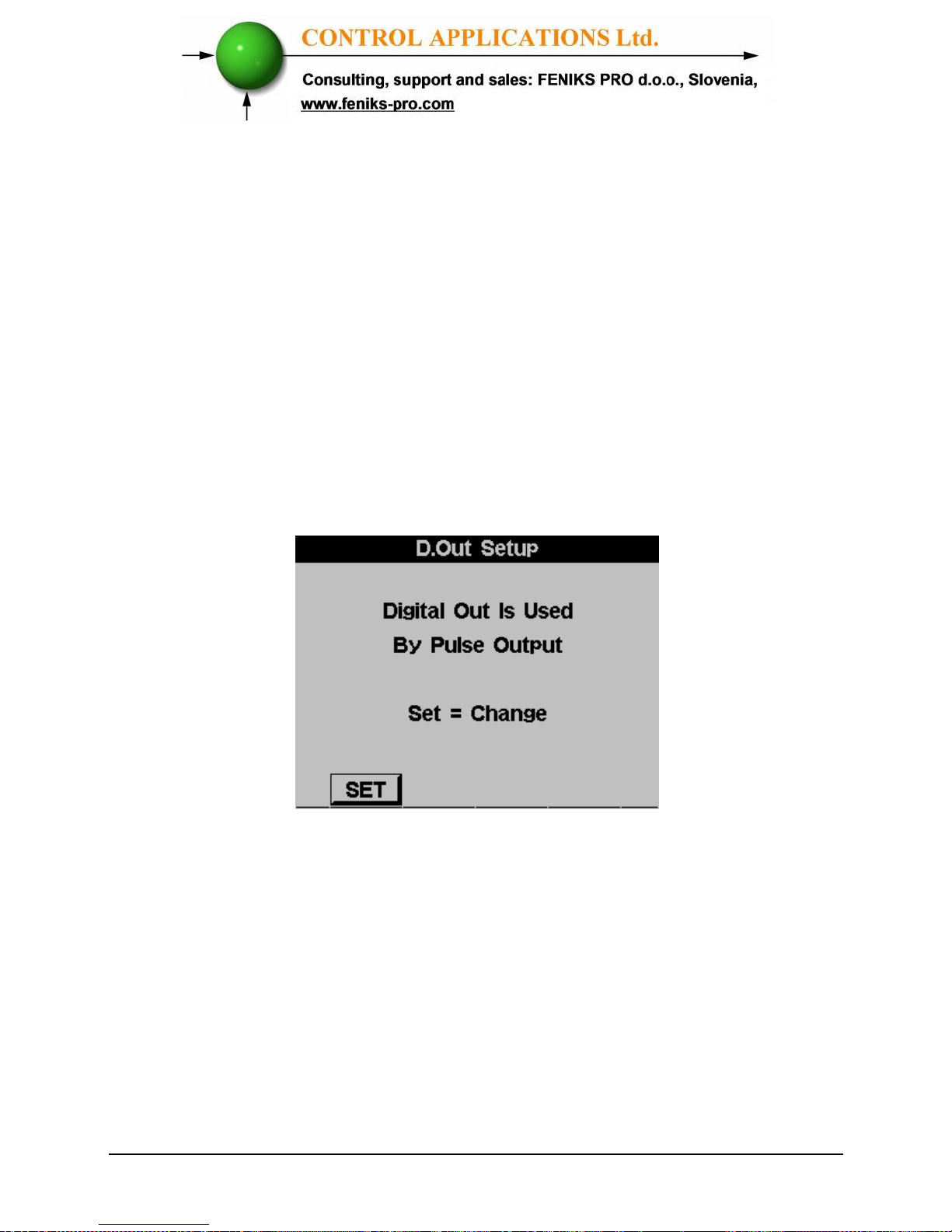
The digital output (chapter 2.5) can be used as a pulse output, each
pulse equivalent to pre define energy consumption value, in order
to set the pulse output - See Section 4.0 for instructions to arrive
at the Technical Menu.
From Technical Menu:
1 Scroll to SET ENERGY PULSE
2 Click “ENTER”.
3 If the Digital Out was defined to be used
for alarm the following message screen
will appear
Figure 4.9 Changing Digital Out usage
4 Click SET (F1) to access the change mode
and click again SET (F1) in order to
change between alarm mode to energy
pulse out mode.
5 The SET ENERGY PULSE screen
appears:
Page 45
45
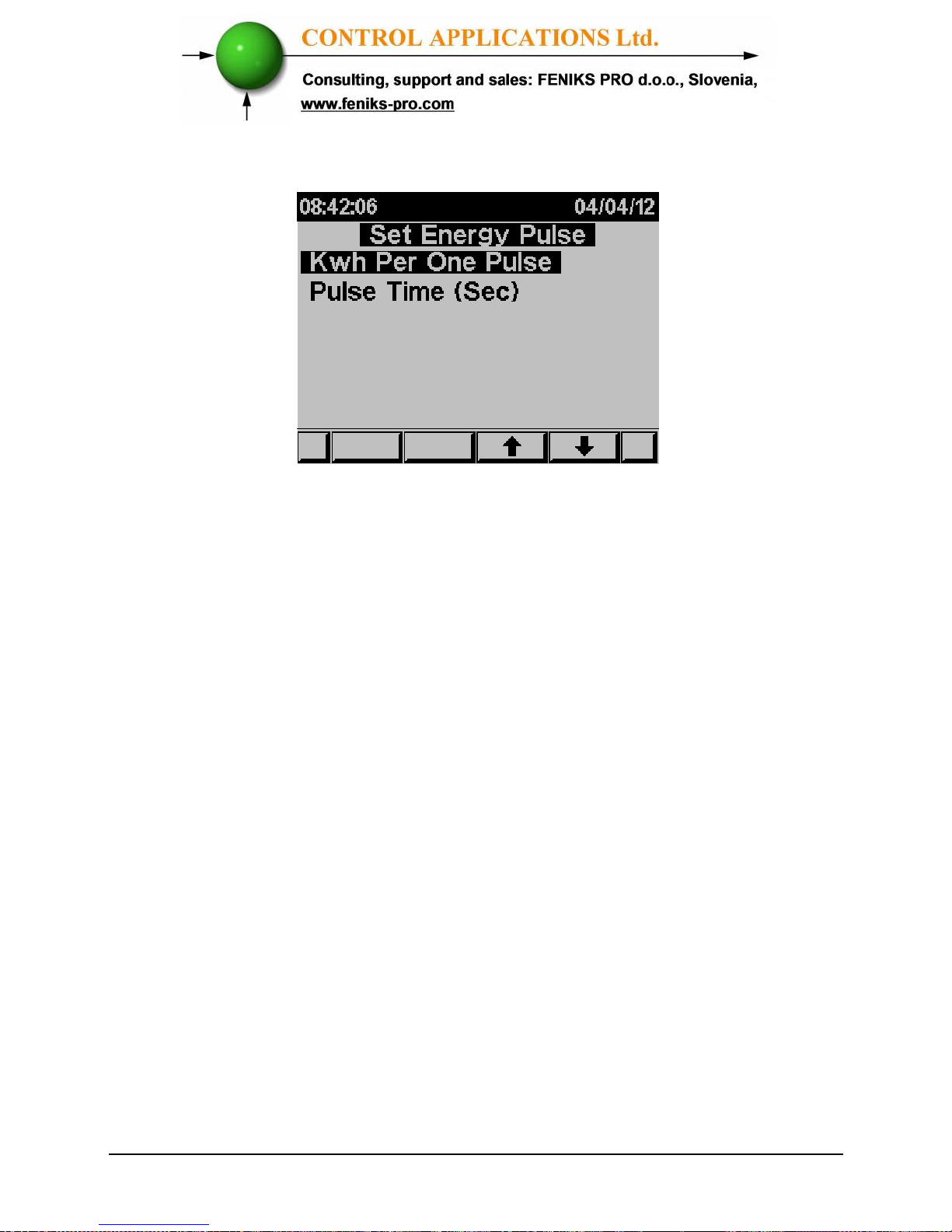
Figure 4.10 Set Energy Pulse
6 In order to set the KWH value pre pulse
scroll to KWH Per One Pulse and click
"ENTER".
7 In order to define how wide is the pulse
scroll to Pulse Time and click "ENTER".
8 Please note that while you are using the
output for energy pulse usage you cannot
use the same output for alarms.
4.7 — Delta/Open Delta/Star Electrical network
definition
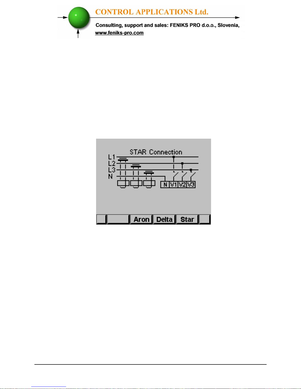
The ELNet LT
can be installed in three types of electrical
networks:
DELTA – a system without neutral line.
Open Delta (Aron) – a system without neutral line.
STAR – a system with neutral line
.
Page 46
46
In order to change the type of the electrical network connected to
the ELNet LT See Section 4.0 for instructions to arrive at the
Technical Menu.
1 From Technical Menu scroll to "Next" then to "Wiring” and
Click “ENTER”.
2 Scroll to “Delta/Star System”.
3 Click “ENTER”.
The Connection screen appears
Figure 4.11 Wiring Connections
4 Use “F2”, “F3” or "F4" in order to change the connection
type. When you are using "DELTA"/”OPEN DELTA”
networks the currents (line currents) and the voltages
(between phases) are not in the same phase therefore part of
the measurements are not applicable and part of the display
screens are not applicable.
Page 47
47
CHAPTER 5 —
FRONT PANEL DISPLAYS
In this chapter you will find instructions on how to obtain the
readings that the ELNet LT
Energy & Powermeter
provides,
e.g., Current, Voltage Power, Power Factor, Energy, and Power
quality.
5.1 — Current Voltage & Frequency
To display Current Voltage and Frequency for all 3 Phases
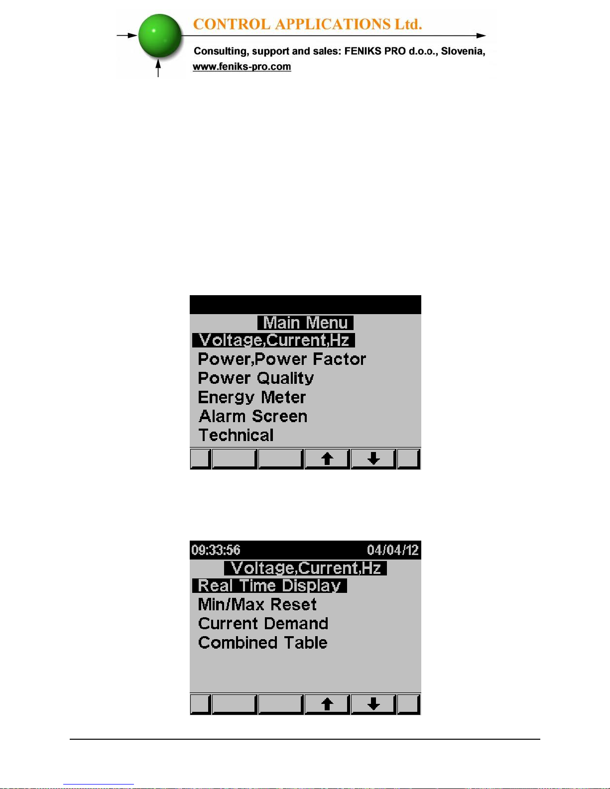
1 From Main Menu scroll to Voltage, Current, Hz.
Figure 5.1 Main Menu
2 Click “ENTER”.
The Current Voltage and Frequency screen appears
Figure 5.2 Voltage, Current, Hz
Page 48
48
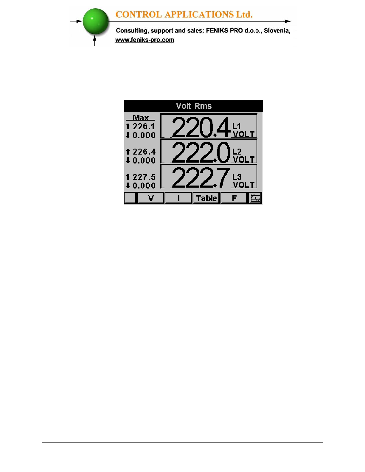
3 Scroll to REAL TIME DISPLAY and click “ENTER”
The Current Voltage and Frequency screen appears
Figure 5.3 Voltage screen
4 Use “F1” in order to display voltage values.
5 Use “F2” in order to display current values.
6 Use “F3” in order to display Current and Voltage
table view.
7 Use “F4” in order to display Frequency values.
Page 49
49
5.2 — Reset I , V , F Peak values
In order to clear old peak values
1 From Main Menu scroll to Voltage, Current, Hz.
2 Click “ENTER” The Current Voltage and Frequency screen
appears.
3 Scroll to MIN/MAX RESET and click “ENTER”.
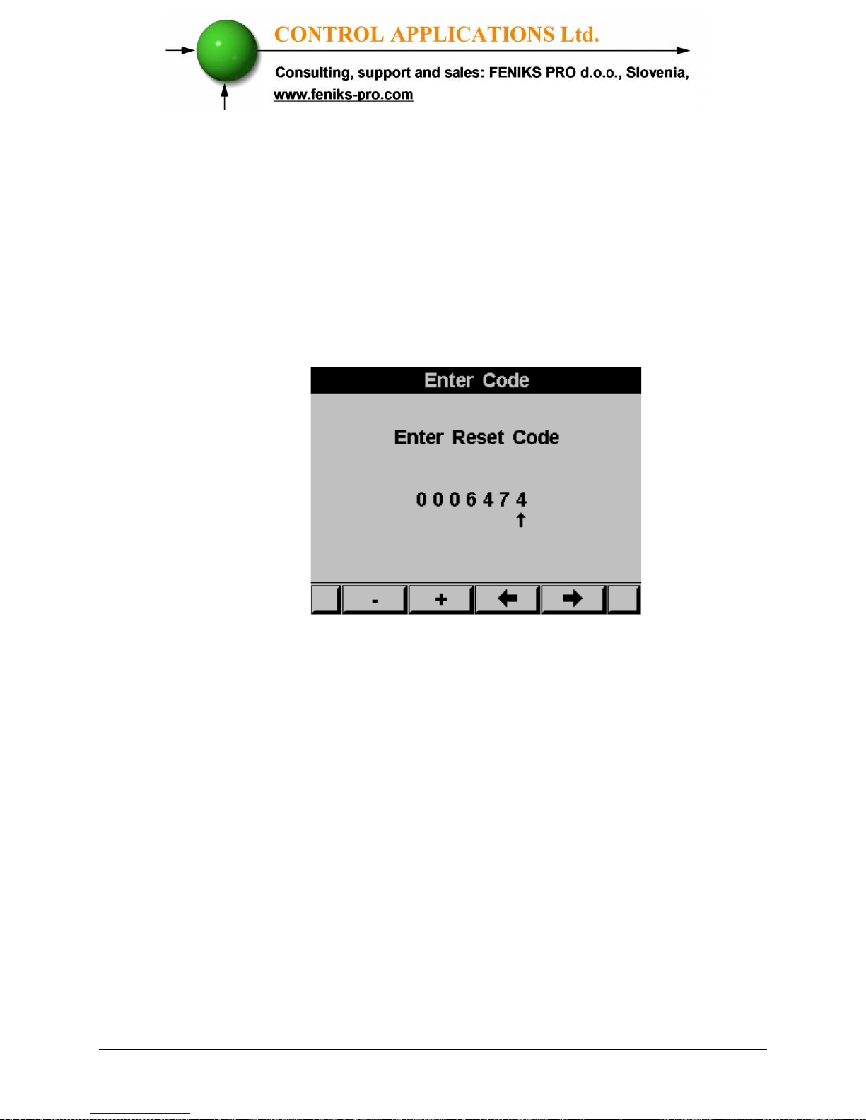
The Enter Code screen appears
Figure 5.4 Enter reset code
In order to clear old peak values enter password 6474
.
Use the buttons F3 & F4 to move the cursor, to set the value
use buttons F1 &F2.
5.3 — Leakage Current (LTP only)
Measuring the leakage current provides a very important safety
indication. If the leakage current exceeds the required safety
standards level a special and urgent examination of the electrical
system is required. ELNet LTP Energy & Powermeter
measures the leakage current by using the existing standard
measurement current transformers.
Page 50
50
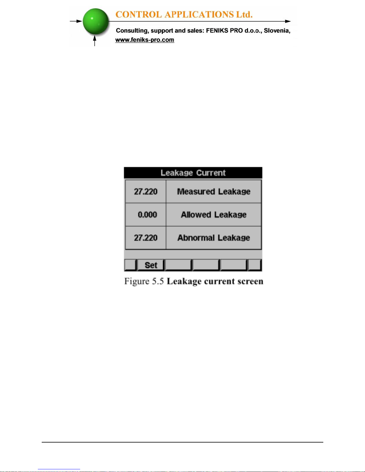
To display the Leakage Current.
1 From Main Menu scroll to Voltage, Current, Hz.
2 Click “ENTER”.
The Current Voltage and Frequency screen appears.
3 Scroll to Leakage Current and click “ENTER”
The Leakage Current screen appears
4 In order to set the Allowed Leakage level, click on the F1
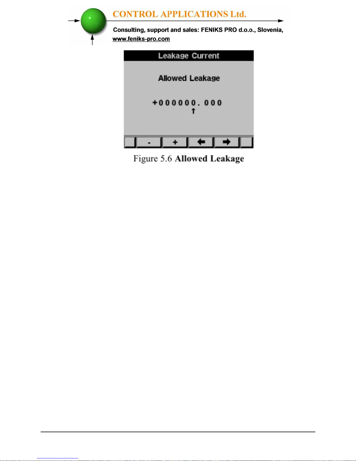
button.
The Allowed Leakage Current screen appears
Page 51
51
Use the buttons F3 & F4 to move the cursor, to set the value
use buttons F1 &F2.
5.4 — Power Display
5.4.1 — Real time power display
To display Power for all 3 phases
1 From Main Menu scroll to Power, power factor Display.
2 Click “ENTER”.
Page 52
52
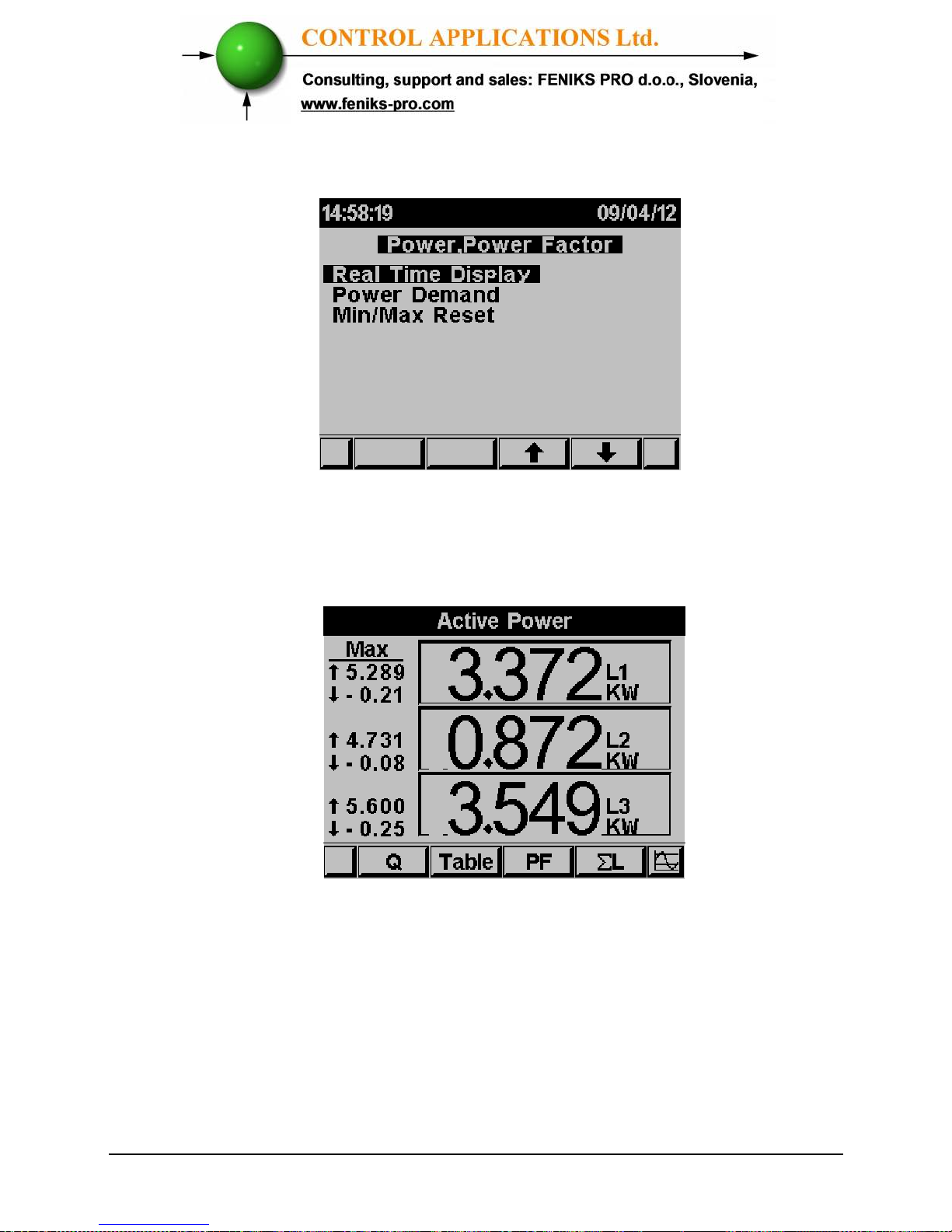
The Power, Power factor screen appears
Figure 5.7 Power, Power factor
3 Scroll to REAL TIME DISPLAY and click “ENTER”.
The real time Power, Power factor screen appears
Figure 5.6 Power factor
4 Use “F1” in order to display Reactive Power values.
5 Use “F2” in order to display Power values table view.
6 Use “F3” in order to display Power Factor values.
7 Use “F4” in order to display total 3 lines active reactive and
apparent power values.
Page 53
53
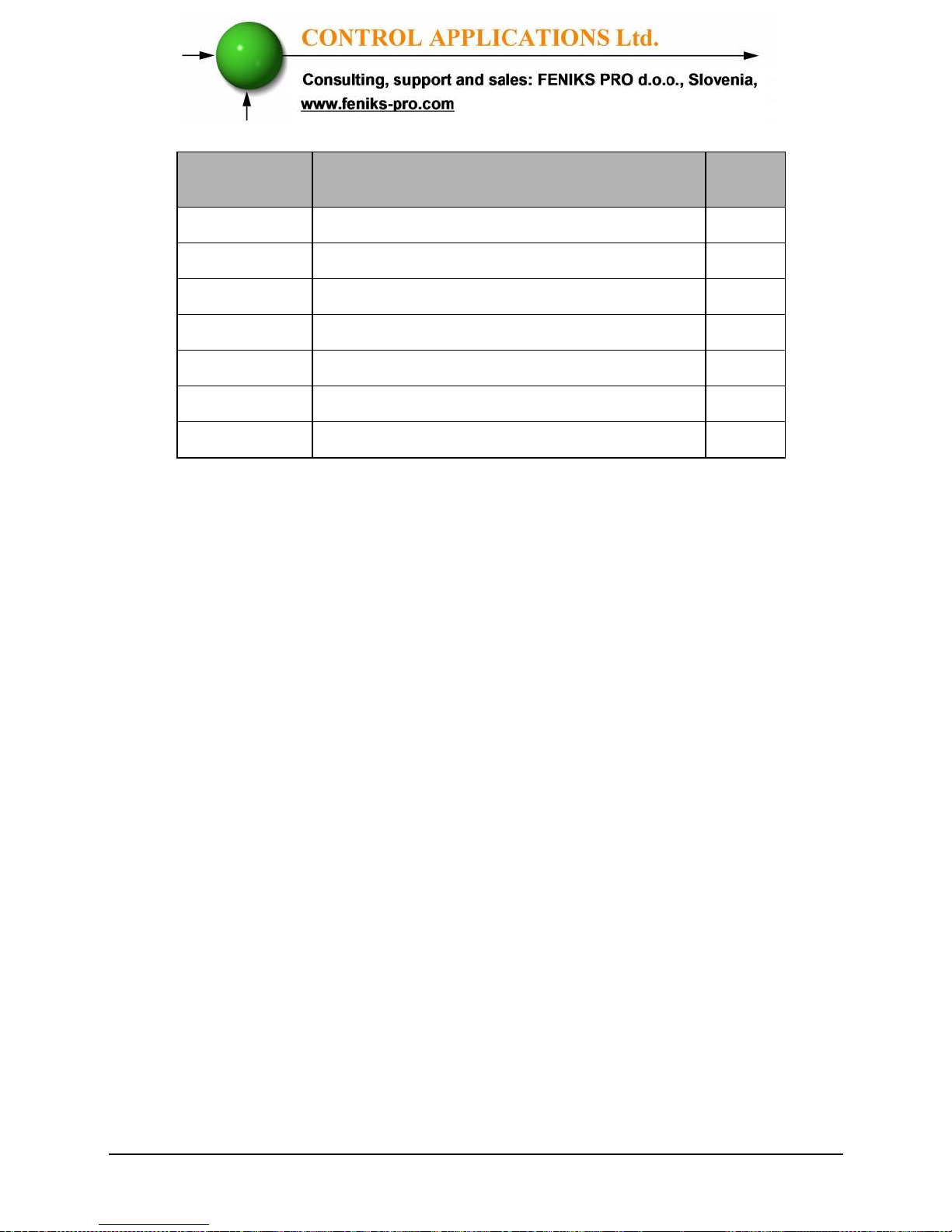
Parameter
Description
Unit
P Active Power for each Line Watts
Q Reactive Power for each Line VAR
S Apparent Power for each Line VA
Σ P Total Active Power for all 3 Lines Watts
Σ Q Total Reactive Power for all 3 Lines VAR
Σ S Total Apparent Power for all 3 Lines
VA
PF Power Factor
Table 5.1 Power Readings
5.4.2 —Reset power peak values
To display /reset power peak value
1 From Main Menu scroll to Power, power factor Display.
2 Click “ENTER”. The Power, Power factor screen appears.
3 Scroll to MIN/MAX RESET and click “ENTER” in order to
clear power peak value and power factor peak values.
4 In order to clear old peak values enter password 6474.
5 Use the buttons F3 & F4 to move the cursor, to set the value
use buttons F1 &F2.
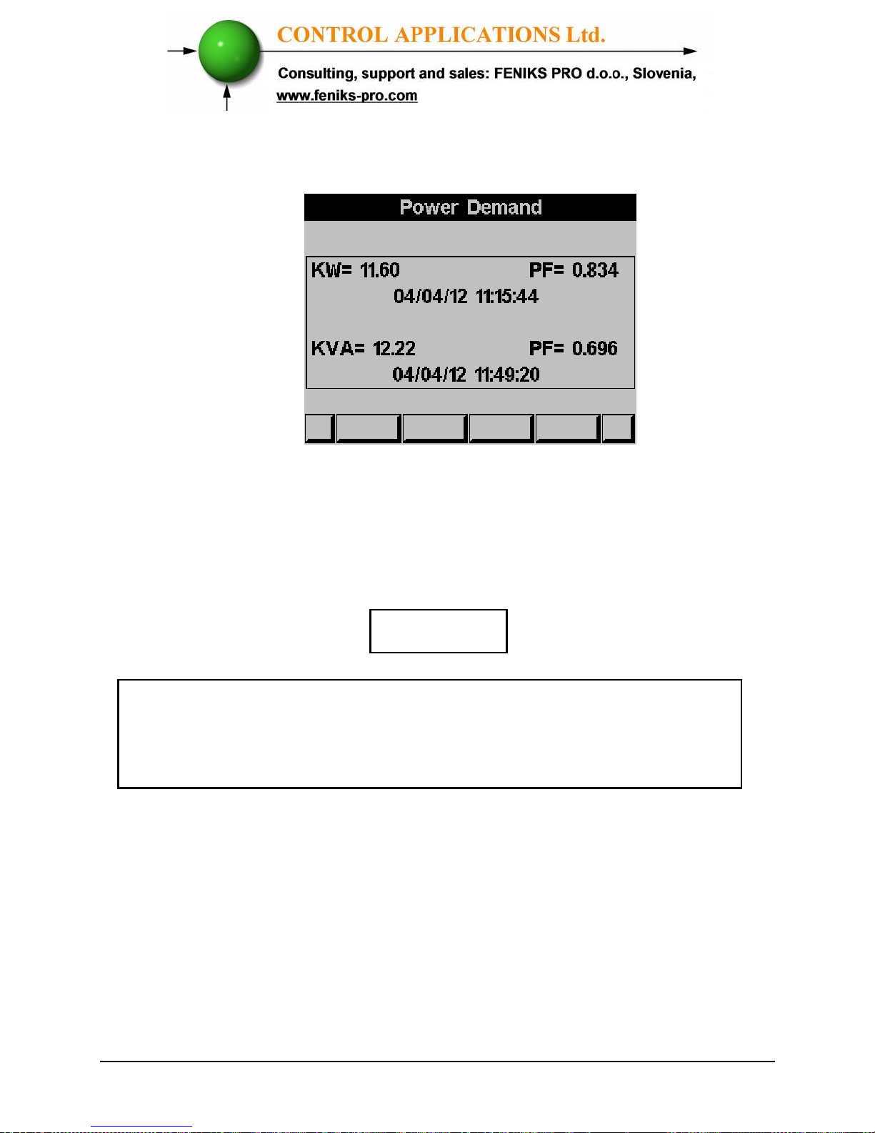
5.4.3 — Power Demand
To display Power demand within two dates
1 From Main Menu scroll to Power, power factor
Display.
2 Click “ENTER”. The Power, Power factor screen
appears.
Scroll to POWER DEMAND and click “ENTER” in order to
display power demand values.
Page 54
54
The Power Demand screen appears
Figure 5.9 Power Demand
5.4 —
Power Quality
NOTE!
Poor Harmonics could invoke a fine and damage to
the electrical system and can be improved by adding
filters.
The ELNet LT
Energy & Powermeter is
capable of displaying
Harmonics in Wave Form Graph, Harmonics Bar Graph, for
Voltage and Current.
Page 55
55
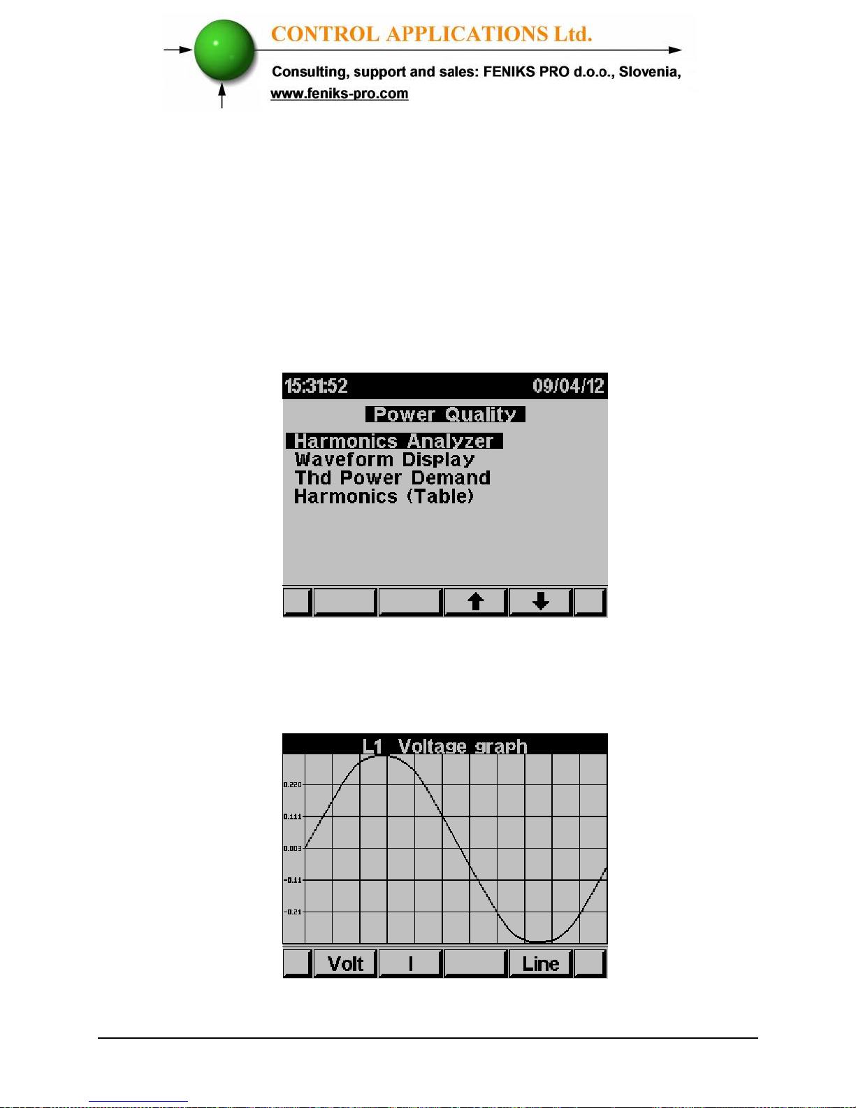
5.5.1 — Wave Form Display
To display Wave Form Graphs
1 From Main Menu scroll to Power Quality.
2 Click “ENTER”
.
The Power Quality screen appears
Figure 5.8 Power Quality
3 Scroll to Waveform Display and click “ENTER”.
The Wave form Graphs screen appears
Figure 5.11 Voltage Graph
Page 56
56
NOTE!
Available Waveform Graphs
1. Volts Line 1, Line 2 and Line 3
2. Current Line 1, Line 2 and Line 3
Use “F1” in order to display voltage waveform.
Use “F2” in order to display current waveform
Use “F4” in order to toggle between L1, L2, L3.
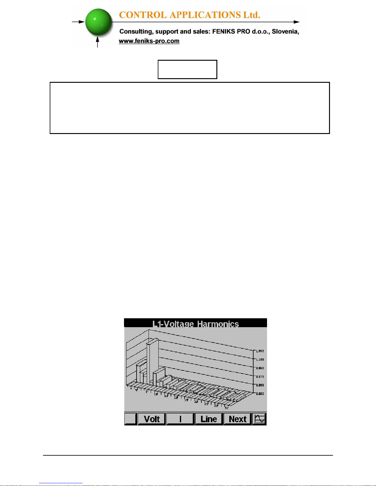
5.4.2 — Harmonics Analyzer & THD
For analyzing and display Harmonics Bar Graphs & THD
1 From the Main Menu scroll to Power Quality Display.
2 Click
“ENTER”
.
The Power Quality screens appear - See
Figure 5.18.
3 Scroll to Harmonics analyzer and click “ENTER”.
The Harmonics current Bar Graph screens appear
Figure 5.10 Harmonics bar Graph
Page 57
57
Use “F1” “F2” in order to toggle the display between current
waveform and voltage waveform.
Use “F3” in order to toggle between L1, L2, L3 and All together.
Use “F4” in order to display and toggle between the harmonics
values up to the 64
th
harmony.
NOTE!
The bar graph of the 1st Harmonics (100%) is shown
without proportion to the other harmonics in order to
display properly all the other harmonics.
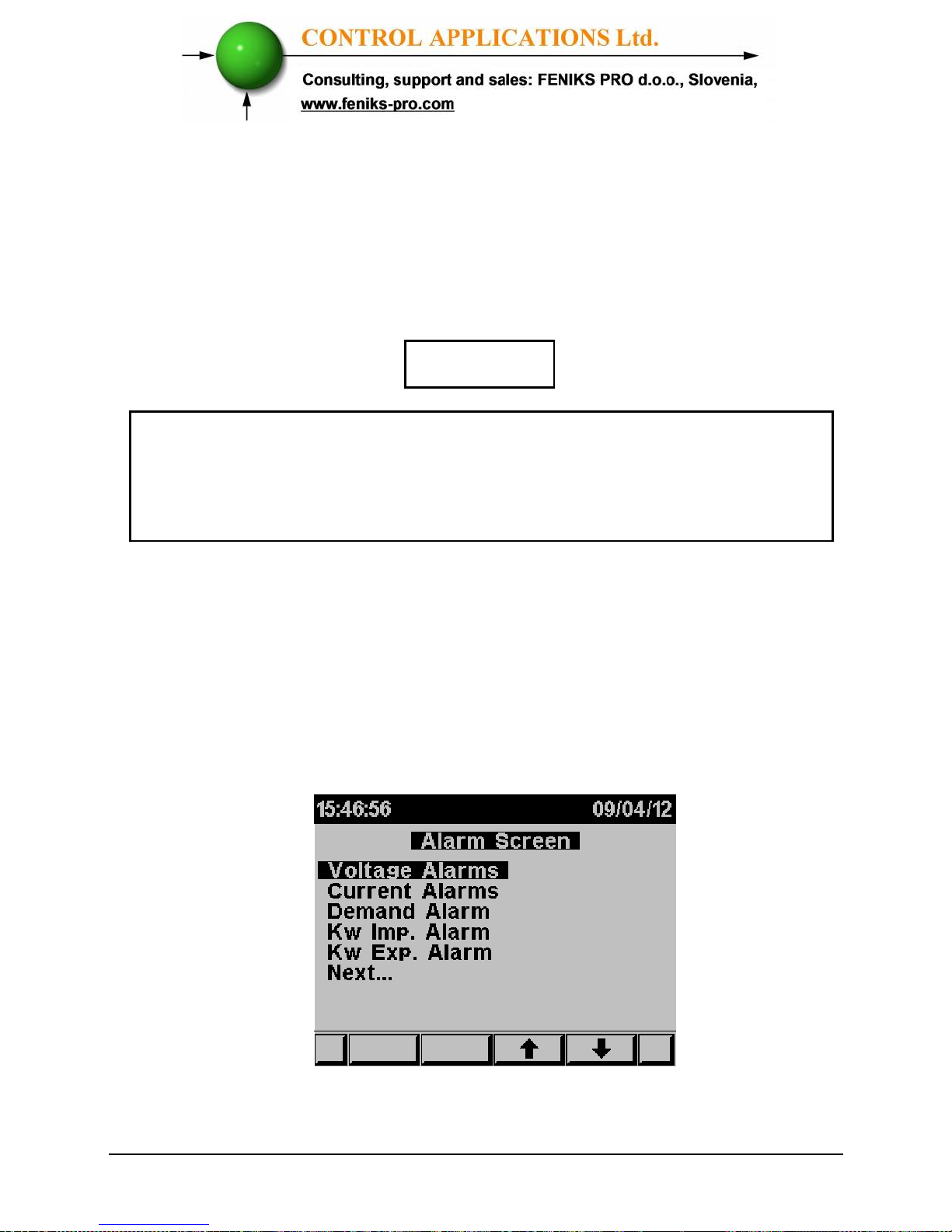
5.4.3 — Alarm Setup
To set the alarm level for electrical measurements
1 From Main Menu scroll to Alarm Screen.
2 Click
“ENTER”
.
The Alarm Screen screens appear.
Figure 5.11 Alarm Screen
Page 58
58
3 Scroll to Alarm setup and click “ENTER”.
The Alarm setup screens appear, and you will be requested
to select the electrical measurement to be defined (voltage/
current / demand / KW IMP. / KW EXP) by pressing, “Enter”
and set the alarm levels.
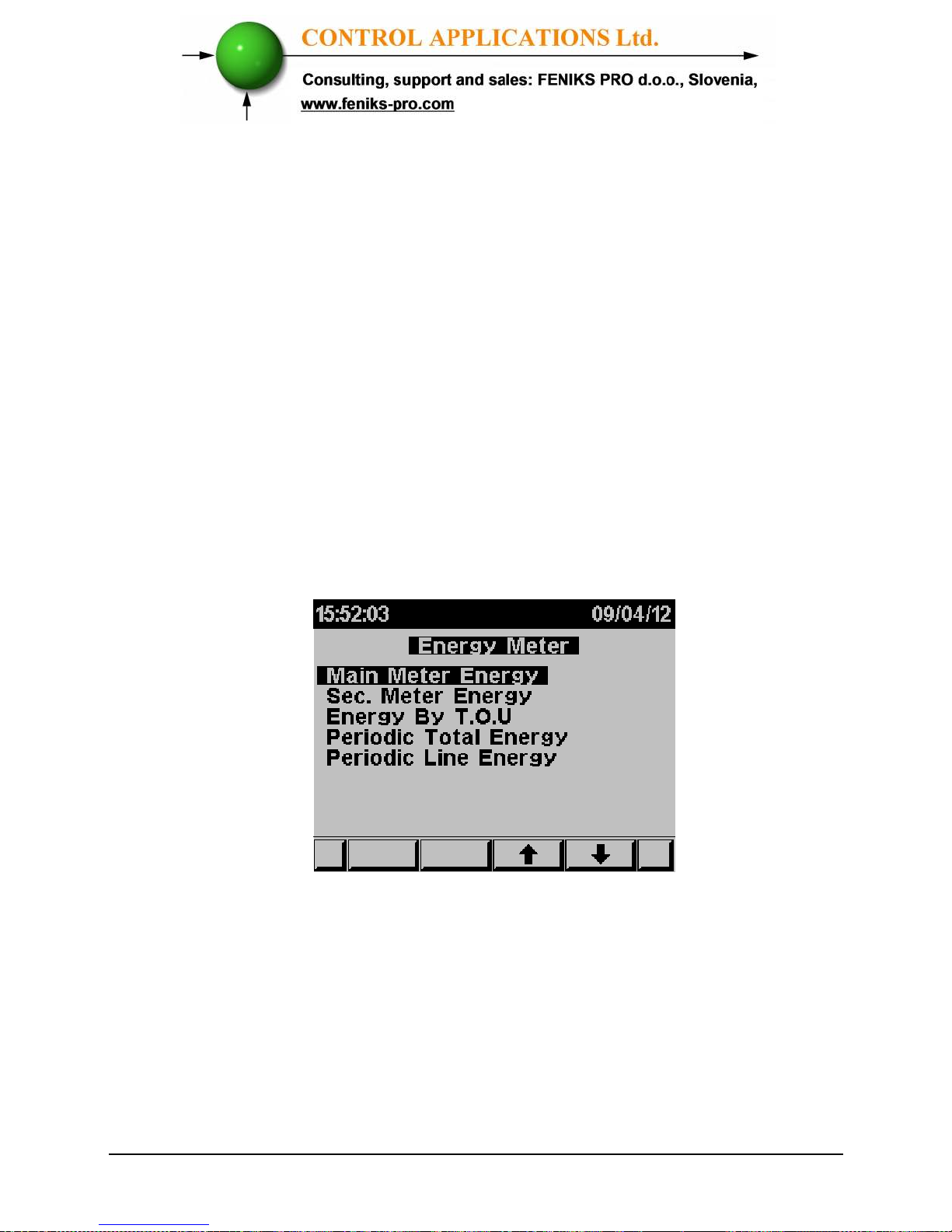
5.6 — Energy Metering
To display active reactive and Apparent Energy values
1 From Main Menu scroll to ENERGY METER.
2 Click “ENTER”.
The Energy Meter screen appears
Figure 5.14 Energy meter
Page 59
59
5.6.1 — Main Energy Meter
This meter will display the total energy that was measured and accumulated in
the meter from the moment the meter was connected to the power. This meter
is non erasable and the total energy that was measured and accumulated
cannot be changed or deleted.
By using the sub menu you will be able to:
By using “F1” The ELNet will display the amount of the energy used for
each rate:
RT1 = Rate number 1
RT2 = Rate number 2
RT3 = Rate number 3
ALL= All rates
By using “F2” The ELNet will display the amount of the energy used for
each line:
L1 = Line number 1
L2 = Line number 2
L3 = Line number 3
ALL= All Lines
By using “F3” The ELNet will display the amount of the active, reactive and
apparent energy:
P = only active energy
Q = only reactive energy
P = only Apparent energy
By using “F4” The ELNet will display the amount of the imported energy
and the amount of the exported energy:
EXP = energy exported
IMP= energy imported
Page 60
60
5.5.2 — 2nd. Energy meter
This meter will display the total energy that was measured and accumulated in
the meter from the last “clear” of the accumulated energy data.
The accumulated energy data in this meter can be erasable (“cleared”) by the
user.
By using the sub menu you will be able to:
By using “F1” The ELNet will display the amount of the energy used for each
rate:
RT1 = Rate number 1
RT2 = Rate number 2
RT3 = Rate number 3
ALL= All rates
By using “F2” The ELNet will display the amount of the energy used for each
line:
L1 = Line number 1
L2 = Line number 2
L3 = Line number 3
ALL= All Lines
By using “F3” The ELNet will display the amount of the active, reactive and
apparent energy:
P = only active energy
Q = only reactive energy
P = only Apparent energy
By pressing and holding the “F4” button for 6 seconds ELNet will delete the
accumulated energy data:
CLR = Clear / Delete the accumulated energy data
Page 61
61
5.5.3 — T.O.U Energy
The
ELNet LT
Energy & Powermeter record all energy
values according to the T.O.U (time of use) schedule.
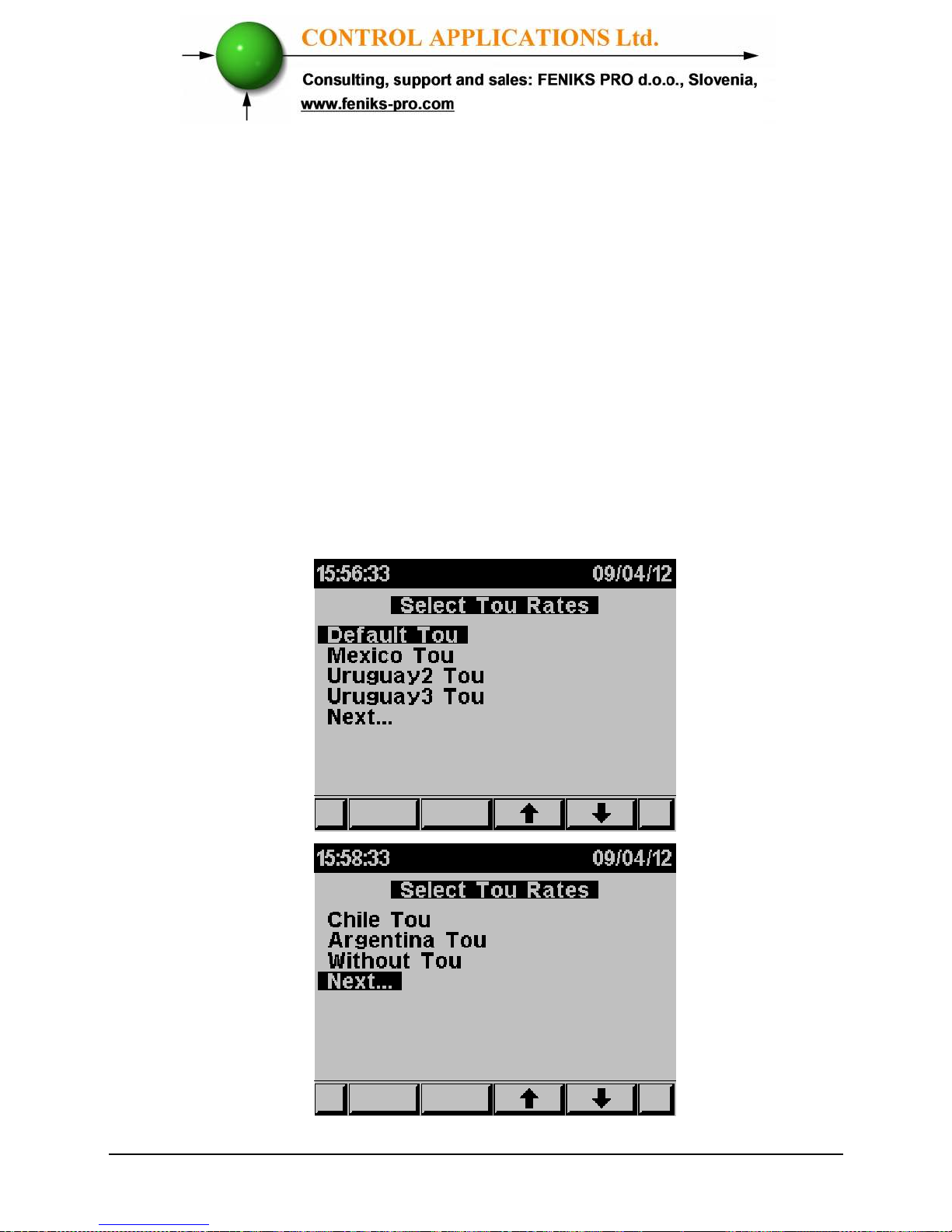
Each country has different T.O.U (time of use) schedule , in order to
select the T.O.U schedule See Section 4.0 for instructions to arrive
at the Technical Menu
1 From Technical Menu scroll twice to NEXT.
2 Scroll to SELECT T.O.U RATES.
3 Click
“ENTER”
.
The Select TOU rates screen appears
Figure 5.13 Select TOU
Page 62
62
4 Select the T.O.U (time of use) schedule.
5.6.4 — Periodic Energy meter
This meter will display the total energy that was measured and
accumulated between two dates which can be defined by the user.
By using the sub menu you will be able to:
By using “F1” (DATE) the user can define two dates in order to set the
period of time for calculating the active energy in this period:
By Using “F2” The ELNet will display the amount of the active energy
used for each rate:
RT1 = Rate number 1
RT2 = Rate number 2
RT3 = Rate number 3
ALL= All rates
By Using “F3” and “F4” The ELNet will display the amount of active
energy, from the selected dates:
MON+ = Change the date by adding a month.
MON– = Change the date by subtracting a month
.
Page 63

63
CHAPTER 6
— COMMUNICATION
MODBUS Protocol
The
ELNet LT
Energy & Powermeter has a serial interface
port allowing direct interface with an external communication
network supporting the MODBUS Protocol.
MODBUS is an Industry Standard, widely known and commonly
used communications protocol. Using MODBUS provides
communication between a PC and up to 247 Powermeter slaves on a
common line - the PC being the master and the powermeters the
slaves. The PC initiates the transaction (either a query or broadcast)
and the Powermeter/s responds. Powermeters respond to the master
PC’s request, but will not initiate any transmission on its own. The
PC sends a single Query transaction and the Powermeter responds in
a single response frame and is capable of only one query and one
response at a time.
6.1 — MODBUS Framing
6.1.1— RTU Transmission Mode
MODBUS uses the standard Remote Terminal Unit (RTU)
transmission mode. RTU mode sends data in 8-bit binary EVEN
parity or 8-bit binary NO parity data format. For the ELNet LT
Energy & Powermeter
to successfully communicate, choose one in
the communication Set Up.
Page 64
64
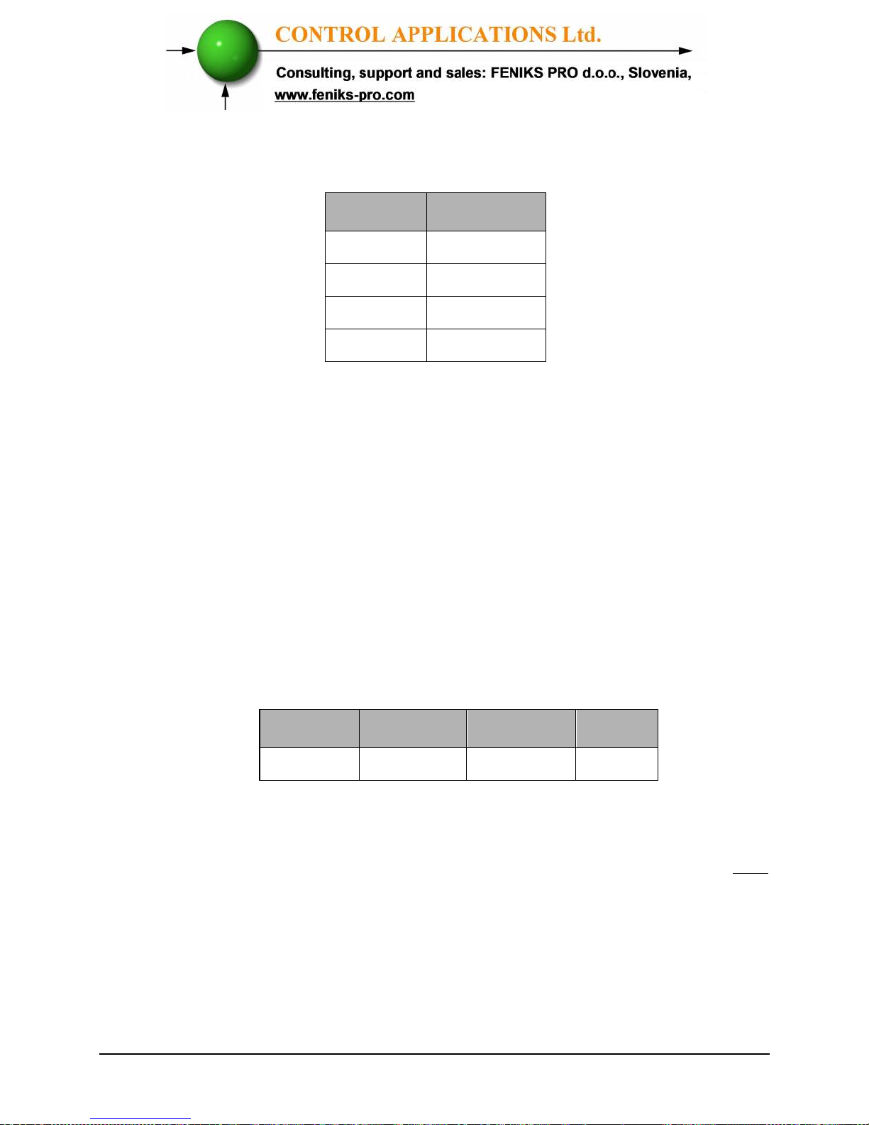
Table 6.1 RTU Data Format
6.1.2 — The RTU Frame Format
Query and response information is sent in frames. Each frame
contains:
Address
Function (See Section 6.1.4 for descriptions of functions),
Data
Check
Address Function
Data Check
8 bits 8 bits N * 8 bits 16 bits
Table 6.2 R T U Message Frame Format
If the receiving device (Powermeter) detects a time laps of five
characters, then it will assume the message is incomplete and will
flush the frame. The device then assumes that the next byte received
will be an address. The maximum query and response message length
is 256 bytes includuing check characters.
Field No. of bits
Start bit 1
Data bits
8
Parity 1
Stop it 1
Page 65
65
6.1.3 — Address Field
Each Powermeter is designated in a network system by a user
assigned address. The Address can be any number between 1 and
247. The Powermeter will only respond to its own specifically
assigned address.
6.1.4 — Function Field
The function field contains the code that tells the Powermeter what
action to perform.
The
ELNet LT
Energy & Powermeter
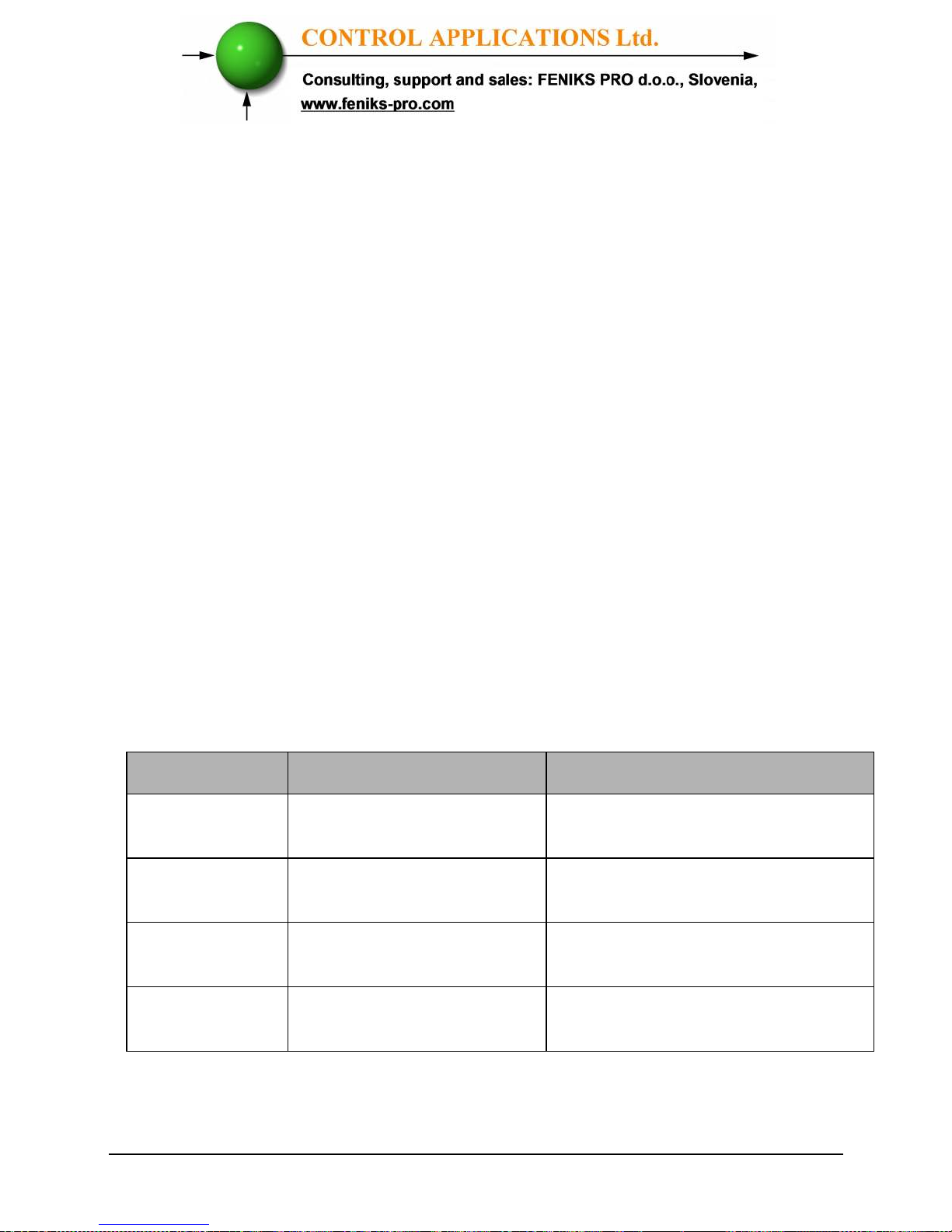
uses and responds to four
standard Message Format Functions.
Function 03
Function 04
Function 06
Function 16
Function Meaning in MODBUS
Action
Function 03
Read holding register Obtain data from Powermeter
(Read register)
Function 04
Read input register Obtain data from Powermeter
(Read register)
Function 06
Preset single register Transmit data to Powermeter
(Write single register)
Function 16
Preset multiple register Transmit data to Powermeter
(Write multiple register)
Table 6.3 Function Codes
Page 66
66
6.1.5 — Data Field
The Data field contains the body of the message and contains
instructions from the PC master to the Powermeter slave to perform
a particular action or respond to a query. The reply message from the
Powermeter will be information contained in one or more of its
registers.
6.1.6 — Check Field
The error check field contains the result of Cyclical Redundancy
Check (CRC). The start of the message is ignored in calculating the
CRC.
For more detailed information on CRC, refer to the MODBUS
Protocol Reference Guide.
Page 67
67
6.2 — Registers for ELNet LT Powermeter
The
ELNet LT
Energy & Powermeter is capable of
supporting either Function 03 or Function 04 Message Format (see
Table 6-3). In a reply to a query from the PC master for a reading
from a particular field, the response from the Powermeter can be
either in Format 03 or Format 04 but will depend on which Format
the query was originally sent.
The difference is significant because by using Function 03 the
ELNet LT will only send the INTERGER part of the field value
requested and the PC master will only display the INTERGER part
of the field value.
Function 04, on the other hand, is capable of sending two separate
halves of the full FLOAT requested information (each half
contained in a separate register). Then it is the task of the PC
master to merge the two halves into a full FLOAT reply (For more
detailed information See IEEE Standard 754 Floating-Point).
E.G. 1 If the user’s PC master supports Function 03, then the reply
will contain the INTERGER part of the field only.
The PC master requests the Voltage from Line1, and the
actual Voltage in that field is 230.5 Volts.
Function 03 will respond with the INTERGER only i.e.
230V.
Page 68

68
E.G. 2 If the user PC master supports Function 04, then the reply
will contain the information stored in the two registers
asssigned to that field and will contain the full, accurate
reply.
The PC master requests the Voltage from Line1, and the actual
Voltage in that field is 230.5 Volts.
Function 04 will respond with a composite reply of both
register 1 and 2 giving the full FLOAT value (in IEEE Format)
from that field i.e. 230.5V.
6.2.1 — Registers addresess
The
ELNet LT
MODBUS registers addresses are updated all the time
and can be downloaded from the following web site:
http://www.ddc.co.il/ELNet-pdf/ELNet_comm.pdf
The MODBUS registers addresses numbering order specify at the above
mentioned web address set as a defaults but can be changed in order to be
fit to the SCADA/HMI drivers.
In order to change the MODBUS registers addresses numbering order:
See Section 4.0 for instructions to arrive at the Technical Menu
1 Scroll to NEXT
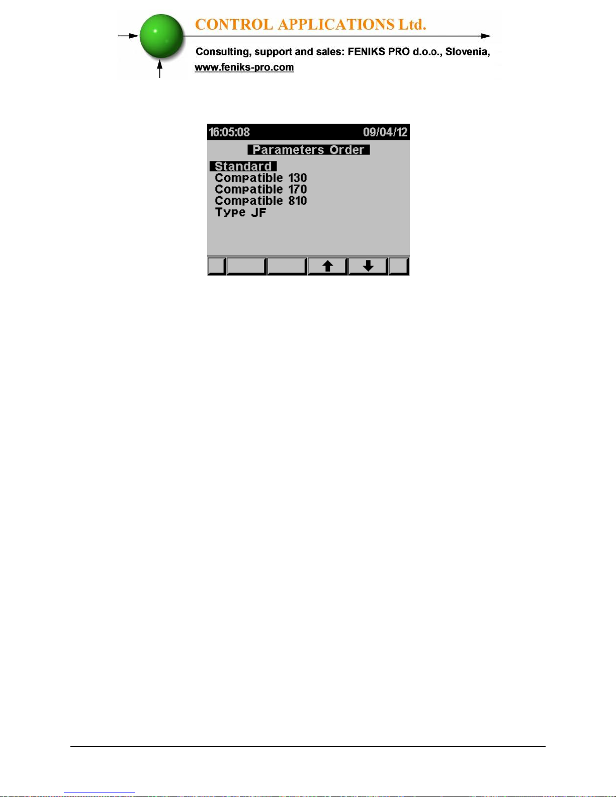
2 Scroll to PARAMETERS ORDER.
3 Click “ENTER”
Page 69
69
The PARAMETERS ORDER screen appears
Figure 6.1 Parameters Order
Select the requested order that compatible to the driver installed in
your SCADA/HMI
6.3 — Communication Connections
The ELNet LT Energy & Powermeter supports RS485
communication. Connections are provided on the Rear
Panel, (Please refer to section 2.3) and are made by means of the
connectors provided.
6.4 — Communication Settings
To enable the User to connect the ELNet LT
Energy &
Powermeter
to a PC computer for successful communications, the
Communication Setup parameters of both must match; i.e. the port
of the PC and the configuration settings of the Power meter.
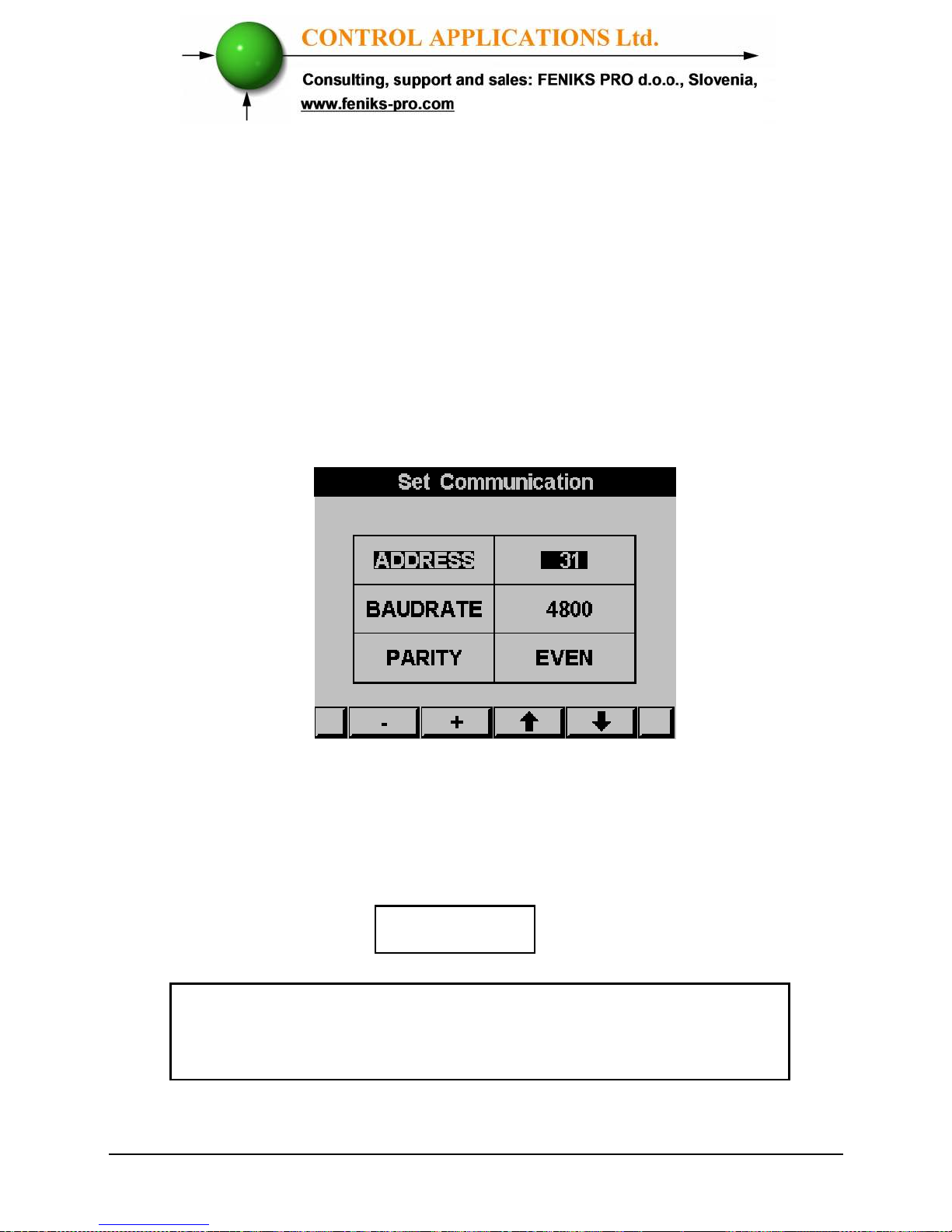
Address
Baud Rate
Parity
Page 70
70
6.4.1 — Communication Address
Each Power meter in a communication system must have its own
unique address.
Because the ELNet LT
Energy & Powermeter
works on
MODBUS, the available addresses are - from ‘1’ to ‘247’
6.4.2 — Baud Rate
The Baud Rate is the communication speed in Bits per second
(BPS) that the ELNet LT
Energy & Powermeter
communicates
with the PC. The better the communication line Quality, the faster
the communications may be.
If the communication line is routed through a “noisy”
environment, it may be necessary to decrease the Baud Rate.
Available Baud Rates for the
ELNet LT Powermeter:
600 bps
1200 bps
2400 bps
4800 bps
9600 bps
19200 bps
6.4.3 — Parity
The choices of parity are either NONE or EVEN (see Section
6.1.1 for description of Parity)
Page 71
71
6.5 — Communication Set Up
6.5.1 — Set up Serial Communications
See Section 4.1 for instructions to reach the Technical Menu.
1 From Technical Menu scroll to Set Communication.
2 Click
“ENTER”
.
3 Scroll to "Serial Comm." and click "Enter".
The Serial Communication Setup screen appears
Figure 6.2 Serial Communication Setup
Use buttons F1 &F2, to set the values
Use the buttons F3 & F4 to move the cursor
NOTE!
When the selection is made it takes immediate affect
with no further action required.
Page 72
72
6.5.2 — Set up Ethernet Communications
See Section 4.1 for instructions to reach the Technical Menu.
1 From Technical Menu scroll to Set Communication.
2 Click
“ENTER”
.
3 Scroll to "Ethernet" and click "Enter".
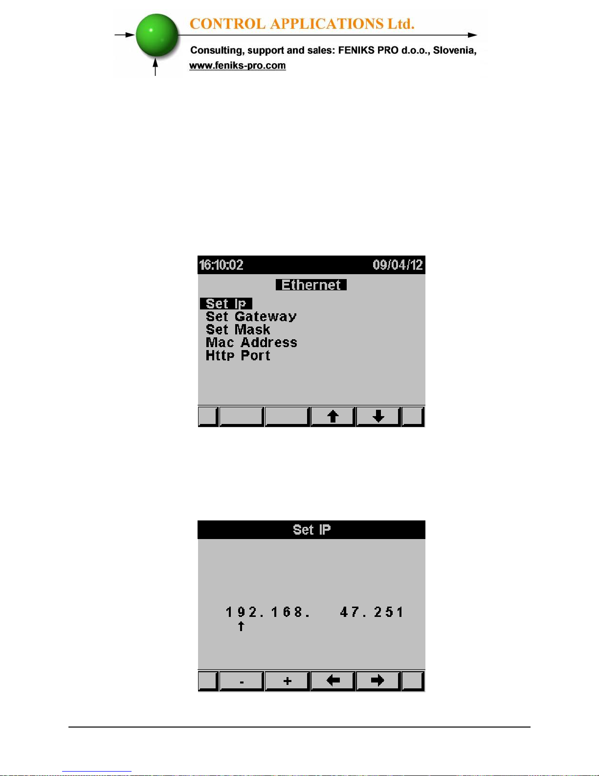
The Ethernet Communication Setup screen appears
Figure 6.3 Ethernet Communication Setup
4 Scroll to "Set IP" and click "Enter".
The IP Setup screen appears
Figure 6.4 IP Setup
Page 73
73
Use buttons F1 &F2, to set the values
Use the buttons F3 & F4 to move the cursor
5 If required: repeat steps 1-4 to set the GATEWAY and
MASK.
6 The MAC address is set automatically however it can
be changed as well by repeating steps 1-4.
6.6 — Communication with UniArt Software
CONTROL APPLICATIONS Ltd propriety software, “UniArt” is
used to Read and Write Registers of the ELNet LT
Energy
Powermeter.
Each Item number in the Registers Table is a unique
field containing information. The UniArt software manages each
Item number as a parameter.
Refer to the UniArt manual how to set up parameters.
To read fields using UniArt
1 Find the reading required in the MODBUS Registers
Table
2 Note the Item Number from the Registers Table
3 Go to the correct File number
Since File capacity in UniArt is limited to 128 parameters,
the information contained in the ELNet LT fields is stored
in several files.
File number is determined by the Item number
File # 0 contains Item number 1 - 128
File
#
1 contains Item number 129 – 256
File # 2 contains Item number 257 – 384
File # 3 contains Item number 385 – 512
Page 74
74
4 Go to the correct Point number within that file
Point number is determined by the formula:
Item number – [FILE X 128] = Point Number
E.G. 1 If the user the wishes to read Voltage Line 2 (Item No 2)
By applying the formula: 2 - [0 X 128] = 2
File = 0 and Point within that file = 2
E.G. 2 If the user the wishes to read 30th Harmonics for Volts Line1
(Item No 330)
By applying the formula: 330 - [2 X 128] = 74
File = 2 and Point within that file = 74
E.G. 3 If the user the wishes to read 7th Harmonic for Current Line 3
(Item No 467)
By applying the formula: 467 - [3 X 128] = 83
File = 3 and Point number within that file = 83
More Examples
E.G. No Item
No
Field Description File Point
1 2 Voltage Line 2 0 2
2 330 30th Harmonics for Volts Line1 2 74
3 467 7th Harmonic for Current Line 3 3 83
4 128 0 128
5 129 1 1
6 256 1 128
7 257 2 1
8 384 20th Harmonics for Volts Line 3 2 128
9 385 21st Harmonics for Volts Line3 3 1
Table 6.4 Function Codes
Page 75
75
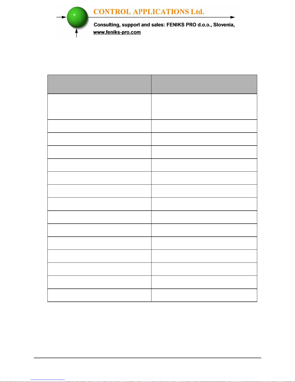
CHAPTER 7 — Specifications
Table 7.1 Specifications
All technical specifications are subject to change without notice.
Item
Description
Power requirements 85-260V AC or 110-300V DC
,60/50 Hz, 5VA
Dimensions (HxWxD) 960x960x80 mm
Shipping Weight 620 gr.
Measuring voltage limits 700VAC
Measuring current limits 6 A
Operating Voltage limits 1000 V
Operating Current limits 50 A
Enclosure material ABS + Anti flame
Display Graphic 64x128
Operating temperature -20 - + 70 C
Storage temperature -20 - + 80 C
Humidity 0- 90 RH%
Voltage input terminals VL – E10 1708
Communication port RS485
Mounting Front Panel Mounting
Page 76
76
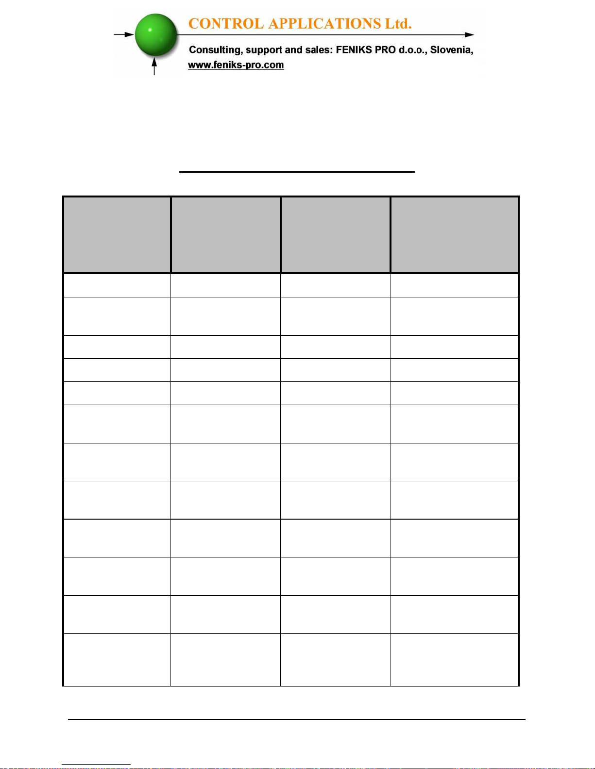
7.1 — Measurement & Display
Measurement & Display (scaling factor 1)
Measurement
Parameter
Display Range
in direct
connection
(scaling factor 1)
Measuring in
direct
connection
(scaling factor 1)
Display Range
Current
0.001 – 6A 0.001 – 6A 0.001 – 99999KA
Neutral Current
(calculated )
0.001 – 6A 0.001 – 6A 0.001 – 99999KA
Voltage L-N
0.000 – 550 V 0.000 – 550 V 0.001 – 99999KV
Voltage L-L
0.000 – 650 V 0.000 – 650 V 0.001 – 99999KV
Frequency (Hz)
45.001-65.001 Hz 45.001-65.001 Hz 45.001-65.001 Hz
Active power
total\phase
0.000W – 99999MW
Reactive power
total\phase
0.000VAR 99999MVAR
Apparent power
total\phase
0.000VA -
99999MVA
Power Factor
(cap.\ind.)
-1.000 ÷ 1.000 -1.000 ÷ 1.000 -1.000 ÷ 1.000
Active Energy
total\phase
0.001WH –
99999999MWH
Reactive Energy
total\phase
0.001VARH -
99999999MVARH
Apparent
Energy
total\phase
0.001VAH -
99999999MVAH
Page 77
77
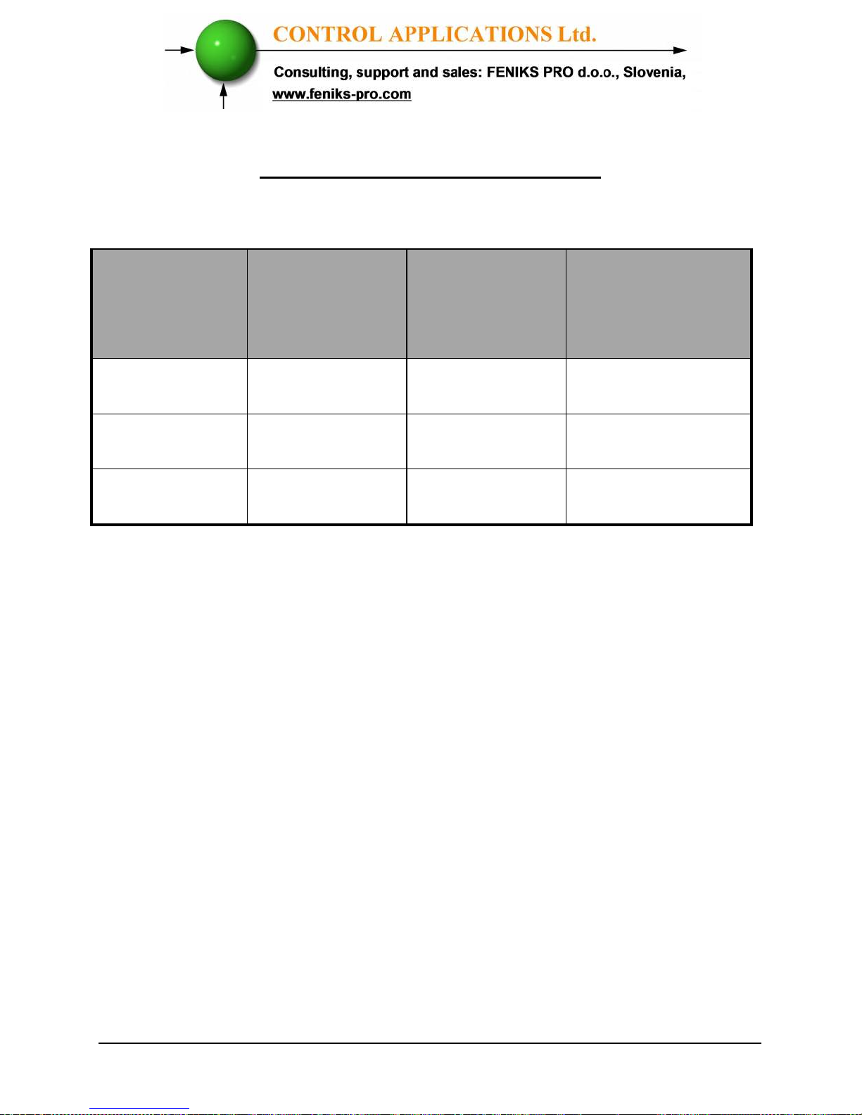
Measurement & Display (scaling factor 1)
Measurement
Parameter
Display Range
in direct
connection
(scaling factor 1)
Measuring in
direct
connection
(scaling factor 1)
Display Range
Harmonic THD
V\I
0.000 – 100%
Partial
Harmonic V\I
0.000 – 100%
Operating hour
meter
99999-HH:MM:SS
Table 7.2 Measurement & Display
Page 78
78
Index
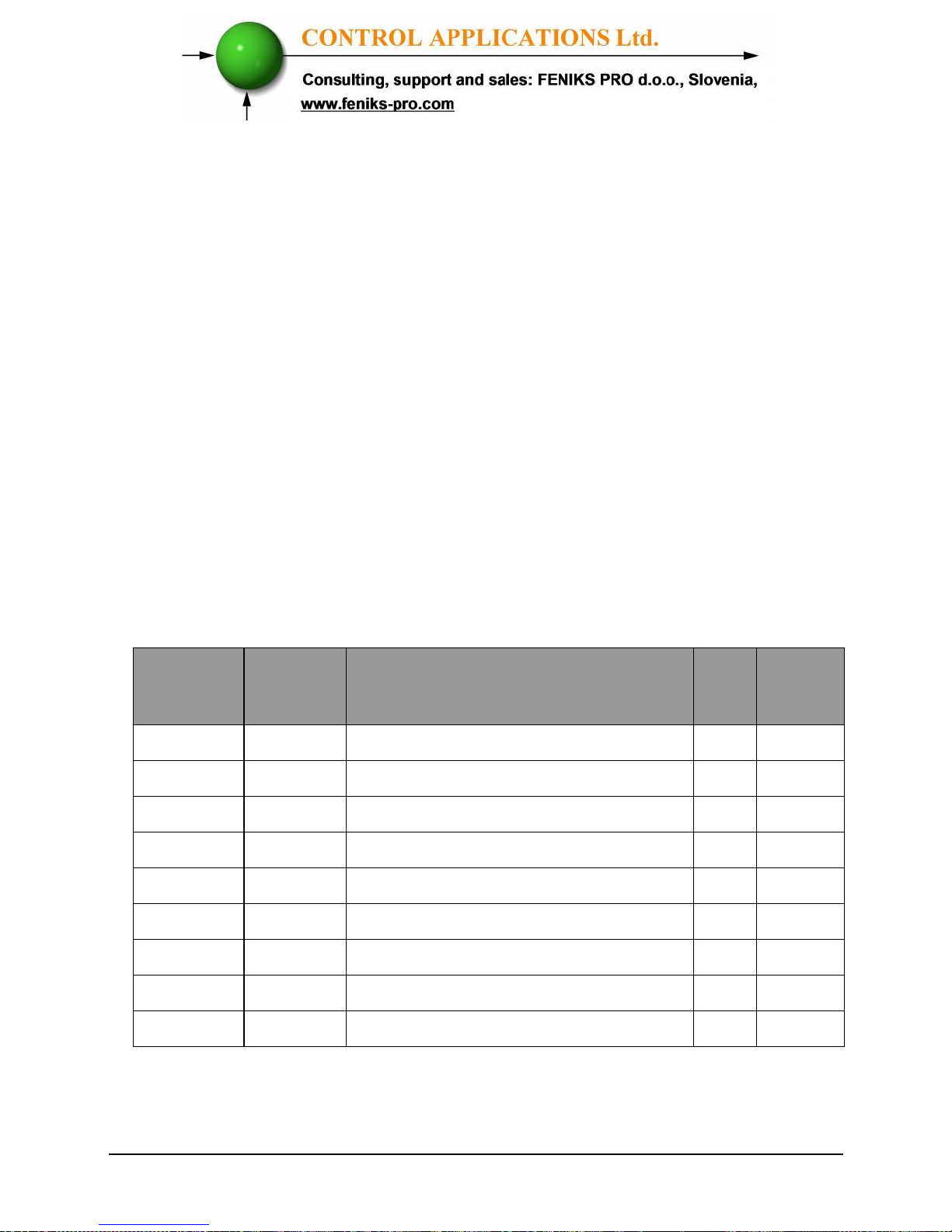
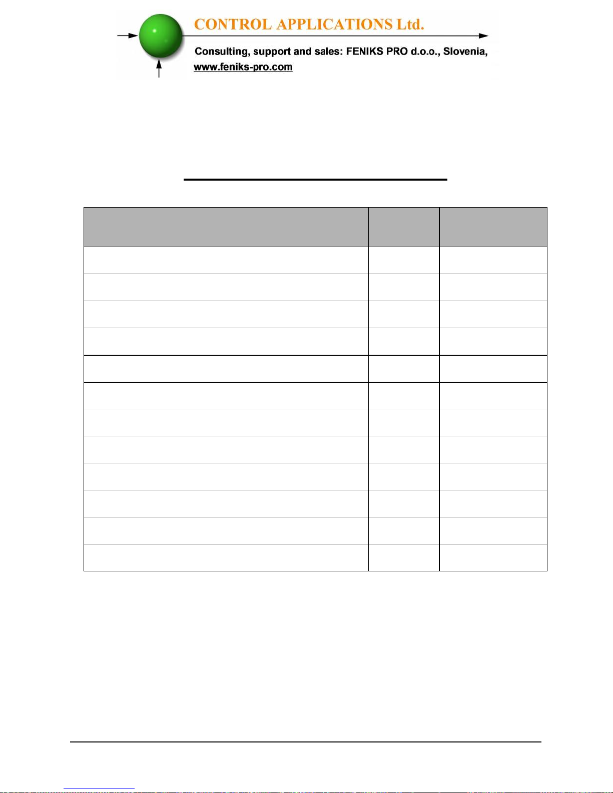
Appendix A — Installation & Configuration Check List
INSTALLATION CHECK LIST
Description
Date Signature
Check contents of packaging
Remove from packaging
Prepare hole
Mount Powermeter
Connect Powermeter power supply
Connect 3 Current Transformers
Connect 3 Voltage lines
Connect Neutral line
Set Current Transformer Ratio
Connect Communication lines
Check Phase Order Connections
Set Time and Date
Appendix A Table - Installation & Configuration Check List
 Loading...