

Page 1

User's Manual for
BeeHive204
Very fast universal 4x 48-pindrive concurrent multiprogramming system with ISP capability
BeeHive4+
Fast universal 4x 48-pindrive concurrent multiprogramming system with ISP capability
BeeProg2
Very fast universal 48-pindrive Programmer with USB/LPT interface and ISP capability
BeeProg+
Universal 48-pindrive Programmer with USB/LPT interface and ISP capability
SmartProg2
Universal 40-pindrive Programmer with USB interface and ISP capability
MEMprog2
Universal memory Programmer
T51prog2
MCS51 Series and Atmel AVR Microcontrollers Programmer with ISP capability
PIKprog2
Microchip PICmicro Programmer with ISP capability
SEEprog
Serial EEPROM Programmer
ELNEC s.r.o.
Presov, Slovakia
12th
April 2011
ELNEC s. r. o.
1
Page 2

This document is copyrighted by ELNEC s.r.o., Presov, Slovakia. All rights reserved. This
document or any part of it may not be copied, reproduced or translated in any form or in any
way without the prior written permission of ELNEC s.r.o.
The control program is copyright ELNEC s.r.o., Presov, Slovakia. The control program or any
part of it may not be analyzed, disassembled or modified in any form, on any medium, for any
purpose.
Information provided in this manual is intended to be accurate at the moment of release, but
we continuously improve all our products. Please consult manual on
www.elnec.com
ELNEC s.r.o. assumes no responsibility for misuse of this manual.
ELNEC s.r.o. reserves the right to make changes or improvements to the product described
in this manual at any time without notice. This manual contains names of companies,
software products, etc., which may be trademarks of their respective owners. ELNEC s.r.o.
respects those trademarks.
COPYRIGHT © 1991 - 2010
ELNEC s.r.o.
ELNEC s. r. o.
.
2
Page 3

How to use this manual
This manual explains how to install the control program and how to use your programmer. It
is assumed that the user has some experience with PCs and installation of software. Once
you have installed the control program we recommend you consult the context sensitive
HELP within the control program rather than the printed User's Manual. Revisions are
implemented in the context sensitive help before the printed User’s Manual.
thank you for purchasing one of the ELNEC
_____________________________________
Please, download actual version of manual
from ELNEC WEB site (
Dear customer,
programmer.
www.elnec.com), if
current one will be out of date.
ELNEC s. r. o.
3
Page 4

ELNEC s. r. o.
Table of contents
How to use this manual................................................................................................................... 3
Introduction........................................................................................................................................7
Products configuration ....................................................................................................................9
PC requirements ........................................................................................................................... 10
Free additional services: ............................................................................................................... 11
Quick Start .......................................................................................................................................12
Detailed description ........................................................................................................................15
BeeHive204 / BeeHive4+ ................................................................................................................. 16
Introduction ...................................................................................................................................17
BeeHive204 / BeeHive4+ elements ..............................................................................................19
Manipulation with the programmed device ...................................................................................20
In-system serial programming by BeeHive204 / BeeHive4+ ........................................................20
Selftest and calibration check .......................................................................................................22
Technical specification..................................................................................................................24
BeeProg2 / BeeProg+......................................................................................................................29
Introduction ...................................................................................................................................30
BeeProg2 / BeeProg+ elements ...................................................................................................32
Connecting BeeProg2 / BeeProg+ to the PC................................................................................ 33
Manipulation with the programmed device ...................................................................................34
In-system serial programming by BeeProg2 / BeeProg+.............................................................. 34
Multiprogramming by BeeProg2 / BeeProg+ ................................................................................36
Selftest and calibration check .......................................................................................................36
Technical specification..................................................................................................................37
SmartProg2 ......................................................................................................................................42
Introduction ...................................................................................................................................43
SmartProg2 elements ...................................................................................................................44
Connecting SmartProg2 to PC...................................................................................................... 45
Manipulation with the programmed device ...................................................................................45
In-system serial programming by SmartProg2.............................................................................. 46
Selftest .......................................................................................................................................... 47
Technical specification..................................................................................................................47
MEMprog2 ........................................................................................................................................51
Introduction ...................................................................................................................................52
MEMprog2 elements.....................................................................................................................53
Connecting MEMprog2 to PC .......................................................................................................54
Manipulation with the programmed device ...................................................................................54
Selftest .......................................................................................................................................... 54
Technical specification..................................................................................................................55
T51prog2 ..........................................................................................................................................58
Introduction ...................................................................................................................................59
T51prog2 elements ....................................................................................................................... 60
Connecting T51prog2 to PC .........................................................................................................61
Manipulation with the programmed device ...................................................................................61
In-System serial programming by T51prog2................................................................................. 61
Selftest .......................................................................................................................................... 62
Technical specification..................................................................................................................63
PIKprog2...........................................................................................................................................65
Introduction ...................................................................................................................................66
PIKprog2 elements .......................................................................................................................67
4
Page 5

ELNEC s. r. o.
Connecting PIKprog2 programmer to PC..................................................................................... 68
Manipulation with the programmed device ................................................................................... 68
In-System serial programming by PIKprog2................................................................................. 68
Selftest.......................................................................................................................................... 69
Technical specification ................................................................................................................. 70
SEEprog........................................................................................................................................... 73
Introduction................................................................................................................................... 74
SEEprog elements........................................................................................................................ 75
Connecting SEEprog programmer to PC ..................................................................................... 75
Manipulation with the programmed device ................................................................................... 76
Technical specification ................................................................................................................. 76
Setup ................................................................................................................................................ 78
Software setup.............................................................................................................................. 79
Hardware setup ............................................................................................................................ 85
Pg4uw .............................................................................................................................................. 89
Pg4uw-the programmer software ................................................................................................. 90
File................................................................................................................................................ 93
Buffer ............................................................................................................................................ 99
Device......................................................................................................................................... 105
Programmer................................................................................................................................ 132
Options ....................................................................................................................................... 137
Help ............................................................................................................................................ 147
Pg4uwMC....................................................................................................................................... 150
Common notes.............................................................................................................................. 160
Maintenance ............................................................................................................................... 161
Software ..................................................................................................................................... 162
Hardware .................................................................................................................................... 168
ISP (In-System Programming).................................................................................................... 168
Other........................................................................................................................................... 171
Troubleshooting and warranty .................................................................................................... 173
Troubleshooting.......................................................................................................................... 174
If you have an unsupported target device .................................................................................. 175
Warranty terms ........................................................................................................................... 175
5
Page 6

ELNEC s. r. o.
Conventions used in the manual
References to the control program functions are in bold, e.g. Load, File, Device, etc.
References to control keys are written in brackets <>, e.g. <F1>.
Terminology used in the manual:
Device any kind of programmable integrated circuits or programmable devices
ZIF socket Zero Insertion Force socket used for insertion of target device
Buffer part of memory or disk, used for temporary data storage
Printer port type of PC port (parallel), which is primarily dedicated for printer
USB port type of PC port (serial), which is dedicated for connecting portable and
HEX data format format of data file, which may be read with standard text viewers; e.g.
connection.
peripheral devices.
byte 5AH is stored as characters '5' and 'A', which mean bytes 35H and
41H. One line of this HEX file (one record) contains start address and
data bytes. All records are secured with checksum.
6
Page 7

Introduction
Introduction
7
Page 8

This user's manual covers these ELNEC programmers: BeeHive204, BeeHive4+, BeeProg2,
BeeProg+, SmartProg2, MEMprog2, T51prog2, PIKprog2 and SEEprog.
BeeHive204 is very fast universal 4x 48-pindrive concurrent multiprogramming system
designed for high volume production programming with minimal operator effort. The chips are
programmed at near theoretical maximum programming speed. Using build-in ISP connectors
the programmer is able to program ISP capable chips in-circuit.
BeeHive4+ is fast universal 4x 48-pindrive concurrent multiprogramming system
designed for high volume production programming with minimal operator effort. The chips are
programmed at near theoretical maximum programming speed. Using build-in ISP connectors
the programmer is able to program ISP capable chips in-circuit.
BeeProg2 is a fast universal USB/LPT interfaced universal programmer and logic IC tester
with 48 powerful pindrivers. Using build-in ISP connector the programmer is able to program
ISP capable chips in-circuit. This design allows easily add new devices to the device list.
BeeProg2 is a true universal and a true low cost programmer, providing one of the best
"value for money" in today's market.
BeeProg+ is a fast universal USB/LPT interfaced universal programmer and logic IC tester
with 48 powerful pindrivers. Using build-in ISP connector the programmer is able to program
ISP capable chips in-circuit. This design allows easily add new devices to the device list.
BeeProg+ is a true universal and a true low cost programmer, providing one of the best
"value for money" in today's market.
SmartProg2 is a small, fast and powerful USB interfaced programmer of all kinds of
programmable devices. Using build-in ISP connector the programmer is able to program ISP
capable chips in-circuit. It has design, which allows easily add new devices to the device list.
Nice "value for money" in this class.
MEMprog2 is a small, fast and powerful USB interfaced programmer for EPROM, EEPROM,
Flash EPROM, NVRAM, serial EEPROM and static RAM tester. MEMprog2 can be upgraded
to SmartProg2.
T51prog2 is a small, fast and powerful USB interfaced programmer for MCS51 series and
Atmel AVR microcontrollers with ISP capability. T51prog2 enables also programming serial
EEPROM with interface types IIC (24Cxx), Microwire (93Cxx) and SPI (25Cxx). T51prog2 can
be upgraded to SmartProg2.
PIKprog2 is a small, fast and powerful USB interfaced programmer for PICmicro® family
microcontrollers and serial EEPROM with IIC (24Cxx), Microwire (93Cxx) and SPI (25Cxx)
interface types. Using build-in in-circuit serial programming (ISP) connector programmer is
able to program PICmicro® family microcontrollers using serial algorithms. PIKprog2 can be
upgraded to SmartProg2.
SEEprog is universal programmer of all serial EEPROM in 8 pin DIL package. SEEprog
programs EEPROM with interface IIC, SPI and Microwire, and also specialty as for example
digital thermometers. The programmer supports LV (3.3V) devices too.
All our programmers work with almost any IBM PC Pentium compatible or higher, portable or
desktop personal computers. Programmers use the USB port or parallel (printer) port of PC.
ELNEC s. r. o.
8
Page 9

All programmers function flawlessly on Windows operating system (see section PC
requirement).
All programmers are driven by an easy-to-use, control program with pull-down menus, hot
keys and online help. Control program is common for all the ELNEC programmers.
Advanced design, including protection circuits, original brand components and careful
manufacturing allows us to provide a three-years warranty for BeeHive204, BeeHive4+,
BeeProg2, BeeProg+ and SmartProg2 and one-year warranty for MEMprog2, T51prog2,
PIKprog2 and SEEprog on parts and labor for the programmers (limited 25,000 cycle
warranty on ZIF socket). This warranty terms are valid for customers, who purchase a
programmer directly from Elnec company. The warranty conditions of Elnec sellers may differ
depending on the target country law system or Elnec seller’s warranty policy.
Note: We don’t recommend use programmers MEMprog2 and SEEprog for In-circuit
programming. See FAQ on site
www.elnec.com.
Products configuration
Before installing and using your programmer, please carefully check that your package
includes all next mentioned parts. If you find any discrepancy with respective parts list and/or
if any of these items are damaged, please contact your distributor immediately.
Introduction
BeeHive204
BeeHive4+
BeeProg2
BeeProg+
SmartProg2
MEMprog2
T51prog2
PIKprog2
SEEprog
programmer
USB cable
LPT cable
internal power supply
external power supply
diagnostic POD 1x
ISP diagnostic POD 1x
ISP cable 4x
ZIF anti-dust cover 4x
software CD
User’s manual
Quick Guide
registration card
shipping case
• • • • • • •
• • • • • •
- * - - - -
• •
- -
- - - - -
• • • • •
• • • • •
- - - - -
•
• • • • •
• • • • •
• • • • • • •
• •
- -
- - - - -
• • • • •
• • • • • • •
• • • • • • •
-
•
-
-
-
* optional accessories
9
Page 10

PC requirements
Minimal PC requirements
2x BeeHive204
2x BeeHive4+
OS - Windows XP 2000 98 98 98 98 98 95
CPU C2D 2,6GHz P4 P4 P4 P4 P4 P4 P4
RAM [MB] 1000 512 256 256 256 256 256 256
free disk space [MB] 400 200 200 200 200 200 200 200
USB 2.0 high speed
USB 1.1
LPT
CDROM
• •
-
-
• • • • • • • •
Recommended PC requirements
BeeHive204
BeeHive4+
BeeProg2
BeeProg+
SmartProg2
MEMprog2
T51prog2
- - - - - -
-
• • • • •
-
- - - -
•
ELNEC s. r. o.
PIKprog2
SEEprog
-
•
2x BeeHive204
2x BeeHive4+
OS - Windows XP XP XP XP XP XP XP XP
CPU C2Quad C2D C2D C2D C2D C2D C2D C2D
RAM [MB] 2000 1000 1000 512 512 512 512 512
free disk space [MB] 2000 1000 1000 1000 1000 1000 1000 1000
USB 2.0 high speed
LPT IEEE1284
• • • • • • •
-
BeeHive204
BeeHive4+
BeeProg2
BeeProg+
SmartProg2
MEMprog2
T51prog2
PIKprog2
-
- - - -
•
These PC requirements are valid for 2.66/01.2010 version of control program for
programmers. For other version see www.elnec.com.
Free disk space requirement depends also on used IC device size and number of attached
programming sites. For large devices the required free space on disk will be approximately
1000MB + 2x Device size x number of programming sites attached to this PC.
Very easy indication, if your PC in hardware/software configuration is good enough for the
current software version and current situation with PG4UW/PG4UWMC, is to run Windows
task manager (Ctrl+Alt+Del) and see the performance folder. It have to be max. 80% of CPU
usage at full run of programming system.
Note:
10
SEEprog
-
•
Page 11

For convenience, we suggest that you use a supplementary multi I/O card to provide an
additional printer port (LPT2 for example), in order to avoid sharing the same LPT port
between printer and programmer.
Introduction
Free additional services:
Why is it important to use the latest version of the control
program?
• Semiconductor manufacturers continuously introduce new devices with new package types,
manufactured by new technologies in order to support the need for flexibility, quality and
speed in product design and manufacturing. To keep pace and to keep you up-to-date, we
usually implement more than 5000 new devices into the control program within a year.
• Furthermore, a typical programmable device undergoes several changes during its lifetime
in an effort to maintain or to improve its technical characteristics and process yields. These
changes often impact with the programming algorithms, which need to be upgraded (the
programming algorithm is a set of instructions that tells the programmer how to program
data into a particular target device). Using the newest algorithms in the programming
process is the key to obtaining high quality results. In many cases, while the older algorithm
will still program the device, they may not provide the level of data retention that would be
possible with an optimal algorithm. Failure to not use the most current algorithm can
decrease your programming yields (more improper programmed target devices), and may
often increase programming times, or even affect the long term reliability of the programmed
device.
• We are making mistakes too...
Our commitment is to implement support for these new or modified parts before or as soon as
possible after their release, so that you can be sure that you are using latest and/or optimal
programming algorithms that were created for this new device.
• free technical support (phone/fax/e-mail).
• free lifetime software update via Web site.
We also offer the following new services in our customer support program: Keep-Current and
AlgOR.
• Keep-Current is a service by which ELNEC ships to you the latest version of the control
program for programmer and the updated user documentation. A Keep-Current service is
your hassle-free guarantee that you always have access to the latest software and
documentation, at minimal cost. For more information see
• AlgOR (Algorithm On Request) service allows you to receive from ELNEC software support
for programming devices not yet available in the current device list. For more information
see
www.elnec.com.
Free software updates are available from our
Internet address
www.elnec.com.
www.elnec.com.
11
Page 12

ELNEC s. r. o.
Quick Start
12
Page 13

Installing programmer hardware
• connect the USB (or LPT) port of programmer to a USB (or printer) port of PC using
supplied cable
• connect the connector of the power supply adapter to the programmer or turn on
programmer by switch
Installing the programmer software
Run the installation program from the CD (Setup.exe) and follow the on-screen instructions.
Please, for latest information about the programmer hardware and software see
www.elnec.com.
Run the control program
Double click on
After start, control program Pg4uw automatically scans all existing ports and searches for any
connected ELNEC programmer. Program Pg4uw is common for all ELNEC programmers
hence Pg4uw will try to find all supported programmers.
Menu File is used for source files manipulation, settings and viewing directory, changes
drives, changes start and finish address of buffer for loading and saving files and loading and
saving projects.
Menu Buffer is used for buffer manipulation, block operation, filling a part of buffer with string,
erasing, checksum and of course editing and viewing with other items (find and replace
string, printing...).
Menu Device is used for a work with selected programmable device: select, read, blank
check, program, verify, erase and setting of programming process, serialization and
associated file control.
Menu Programmer is used for work with programmer.
Menu Options is used to view and change various default settings.
Menu Help is used for view supported devices and programmers and information about
program version.
Quick Start
Programming a device
1. select device: click on
2. load data into buffer:
a) from file: click on
b) from device: insert device to ZIF and click on
3. insert target device to ZIF
13
Page 14

4. check, if the device is blank: click on
ELNEC s. r. o.
5. program device: click on
6. additional verify of device: click on
14
Page 15

Detailed description
Detailed description
15
Page 16

ELNEC s. r. o.
BeeHive204 / BeeHive4+
16
Page 17

BeeHive204 / BeeHive4+
Introduction
BeeHive204 is very fast universal 4x 48-pindrive concurrent multiprogramming system
designed for high volume production programming with minimal operator effort. The chips are
programmed at near theoretical maximum programming speed.
BeeHive4+ is fast universal 4x 48-pindrive concurrent multiprogramming system
designed for high volume production programming with minimal operator effort. The chips are
programmed at near theoretical maximum programming speed.
BeeHive204 / BeeHive4+ consist of four independent isolated universal programming
modules, based on the BeeProg2 / BeeProg+ programmer hardware. Therefore the sockets
can run asynchronously (concurrent programming mode). Each programming module starts
programming at the moment the chip is detected to be inserted in the socket properly independently on the status of other programming modules. It result three programming
modules works while you replace the programmed chip at the fourth.
Modular construction of hardware - the programming modules works independently - allows
for continuing operation when a part of the circuit becomes inoperable. It also makes service
quick and easy.
Hands-free operation: asynchronous and concurrent operation allows a chip to begin
programming immediately upon insertion of a chip. The operator merely removes the finished
chip and inserts a new chip. Operator training is therefore minimized...
BeeHive204 / BeeHive4+ support all kinds of types and silicon technologies of today and
tomorrow programmable devices without family-specific module. You can be sure the next
devices support require the software update and (if necessary) simple package converter
(programming adapter), therefore the ownership cost are minimized.
Using built-in in-circuit serial programming (ISP) connector, the programmer is able to
program ISP capable chips in circuit.
BeeHive204 / BeeHive4+ provide very competitive price coupled with excellent hardware
design for reliable programming. It has probably best "value for money" programmer in this
class.
BeeHive204 / BeeHive4+ provide very fast programming due to high-speed FPGA driven
hardware and execution of time-critical routines inside of the programmer. It is at least so fast
than competitors in this category, for many chips much faster than most competitors. As a
result, when used in production this programmer waits for an operator, and not the other way
round.
BeeHive204 / BeeHive4+ interfaces with the IBM PC/compatible, portable or desktop
personal computers through USB (2.0) port.
BeeHive204 / BeeHive4+ provides a banana jack for ESD wrist straps connection to easy-toimplement the ESD protection control and also other banana jack for earth wire.
17
Page 18

FPGA based totally reconfigurable 48 powerful TTL pindrivers provide H/L/pull_up/pull_down
and read capability for each pin of socket. Advanced pindrivers incorporate high-quality highspeed circuitry to deliver signals without overshoot or ground bounce for all supported
devices. Pin drivers operate down to 1.8V so you'll be ready to program the full range of
today's advanced low-voltage devices.
BeeHive204 / BeeHive4+ performs on each programming module device insertion test
(wrong or backward position) and contact check (poor contact pin-to-socket) before it
programs each device. These capabilities, supported by overcurrent protection and
signature-byte check help prevent chip damage due to operator error.
BeeHive204 / BeeHive4+ have the selftest capability, which allows run diagnostic part of
software to thoroughly check the health of the each programming module.
BeeHive204 / BeeHive4+ have a built-in protection circuits for eliminate damage of
programmer and/or programmed device due to environment or operator failure. All ZIF socket
pins of BeeHive204 / BeeHive4+ programmer are protected against ESD up to 15kV.
BeeHive204 / BeeHive4+ perform programming verification at the marginal level of supply
voltage, which, obviously, improves programming yield, and guarantees long data retention.
Various socket converters are available to handle device in PLCC, SOIC, PSOP, SSOP,
TSOP, TSSOP, TQFP, QFN (MLF), SDIP, BGA and other packages.
BeeHive204 / BeeHive4+ programmer is driven by an easy-to-use control program with pulldown menu, hot keys and on-line help. Selecting of device is performed by its class, by
manufacturer or simply by typing a fragment of vendor name and/or part number.
Standard device-related commands (read, blank check, program, verify, erase) are boosted
by some test functions (insertion test, signature-byte check), and some special functions
(autoincrement, production mode - start immediately after insertion of chip into socket).
All known data formats are supported. Automatic file format detection and conversion during
load of file.
The rich-featured autoincrement function enables to assign individual serial numbers to
each programmed device - or simply increments a serial number, or the function enables to
read serial numbers or any programmed device identification signatures from a file.
The software also provides a lot of information about programmed device. As a special, the
drawings of all available packages, explanation of chip labeling (the meaning of prefixes
and suffixes at the chips) for each supported chip are provided.
The software provide full information for ISP implementation: Description of ISP connector
pins for currently selected chip, recommended target design around in-circuit programmed
chip and other necessary information.
The remote control feature allows Pg4uw software to be flow controlled by other application
– either using .BAT file commands or using DLL file. For BeeHive204 / BeeHive4+ is remote
control limited for ISP programming only. Please use BeeHive204AP for automated off line
programming.
ELNEC s. r. o.
18
Page 19

BeeHive204 / BeeHive4+
Jam files of JEDEC standard JESD-71 are interpreted by Jam Player. Jam files are
generated by design software which is provided by manufacturer of respective programmable
device. Chips are programmed in ZIF or through ISP connector (IEEE 1149.1 Joint Test
Action Group (JTAG) interface).
VME files are interpreted by VME Player. VME file is a compressed binary variation of SVF
file and contains high-level IEEE 1149.1 bus operations. VME files are generated by design
software which is provided by manufacturer of respective programmable device. Chips are
programmed in ZIF or through ISP connector (IEEE 1149.1 Joint Test Action Group (JTAG)
interface).
Multiple devices are possible to program and test via JTAG chain: JTAG chain (ISP-Jam) or
JTAG chain (ISP-VME).
It is important to remember that in most cases new devices require only a software update
due to the BeeHive204 / BeeHive4+ is truly universal programmer. With our prompt service
you can have new devices can be added to the current list within hours!
Advanced design including protection circuits, original brand components and careful
manufacturing and burning allows us to provide a three-year warranty on parts and labor for
the BeeHive204 / BeeHive4+ (limited 25,000-cycle warranty on ZIF socket).
BeeHive204 / BeeHive4+ elements
1) 48 pin ZIF socket
2) work result LEDs
3) power/sleep LED of site
4) YES! Button
5) ISP connector
6) LED indicator power
19
Page 20

7) power supply connector
8) power switch
9) "GND" connector can be used for grounding of the programmer
"ESD wrist strap" connector is place for attaching of ESD wrist strap
10) temperature controlled fans
11) type B USB connector for PC ↔ BeeHive204 / BeeHive4+ communication cable
Manipulation with the programmed device
After selection of desired device for your work, you can insert it into the open ZIF socket (the
lever is up) and close socket (the lever is down). The correct orientation of the programmed
device in ZIF socket is shown on the picture near ZIF socket on the programmer's cover. The
programmed device is necessary to insert into the socket also to remove from the socket
when LED BUSY light off.
Note: Programmer's protection electronics protect the target device and the programmer
itself against either short or long-term power failures and, partly, also against a PC failure.
However, it is not possible to grant the integrity of the target device due to incorrect, userselected programming parameters. Target device may be not destroyed by forced interruption
of the control program (reset or switch-off PC), by removing the physical connection to the
programmer, but the content of actually programmed cell may remains undefined. Don't
unplug the target device from the ZIF socket during work with devices (LED BUSY shine).
ELNEC s. r. o.
In-system serial programming by BeeHive204 / BeeHive4+
Optimized advanced pindriver deliver programming performance without overshoot or ground
bounce for all device technologies. Pin drivers operate down to 1.8V so you'll be ready to
program the full range of today's advanced low- voltage devices.
The ISP programming solution performs programming verification at the marginal level of
supply voltage, which, obviously, improves programming yield, and guarantees long data
retention.
The ISP programming solution provides also the power supply for the target system.
This ISP programming solution provides very competitive price but excellent hardware design
for reliable programming.
20
Page 21

BeeHive204 / BeeHive4+
The software provide full information for ISP implementation: Description of ISP connector
pins for currently selected chip, recommended target design around in-circuit programmed
chip and other necessary information.
For general definition, recommendation and direction about ISP see section Common notes
/ ISP please.
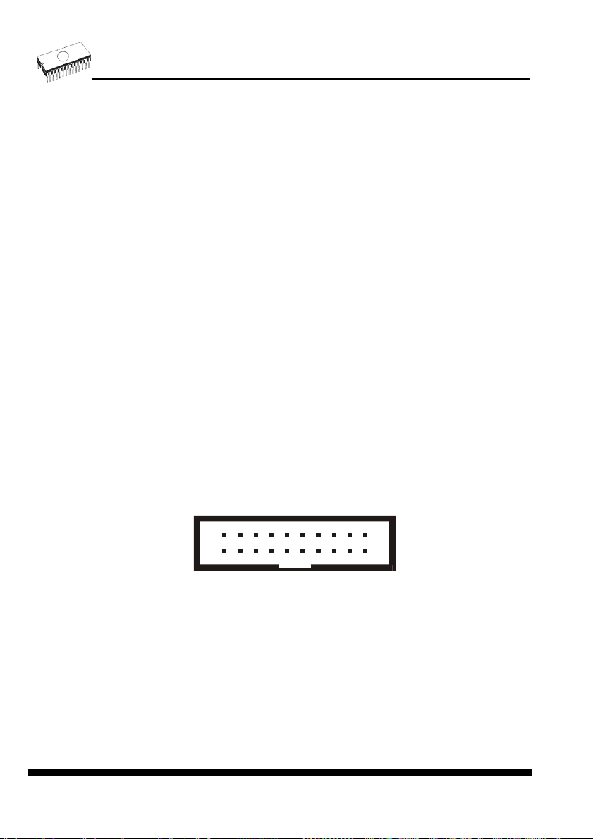
Description of ISP connector
H/L/read driver
H/L
Float
Read
234
1
Front view at ISP connector.
pins 3, 5, 7, 9, 11, 13 of ISP connector
A)
drivers in programmer
RA1
RA2
678910
5
pin of ISP
connector
121314
11
1617181920
15
pin 14 of ISP connector
B)
drivers in programmer
RB1
VCC
RB2
pin of ISP
connector
Pull-up/
Pull-down
RA3
pins 15, 16 of ISP connector
YES!
GND
C) D)
CC1
RC1
RC2
pin of ISP
connector
pin of ISP
CE1
connector
pin of ISP
connector
RD1
GND
E)
H/L
RE1
H/L
Float
Read
Pull-up/
Pull-down
drivers in programmer
RA1 180R, RA2 1k3, RA3 22k,
RB1 10k, RB2 10k,
CC1 1n, RC1 1k3, RC2 22k,
RD1 22k, CE1 1n, RE1 1k3,
21
Page 22

C) Connection of pins 15 and 16 when are configured as logical signal needed for ISP
programming
D) E) When pins 15 and 16 are configured as status of LED OK and LED ERROR
D) before first action with desired ISP device
E) after first action with desired ISP device
Notes: When LED OK or LED ERROR ON (shine), this status is presented as logical H, level
of H is 1,8V - 5V depend on H level of desired ISP device.
When LED OK or LED ERROR OFF (not shine), this status is presented as logical L, level of
L is 0V - 0,4V.
The above mentioned values are provided to understand (and also to exactly calculate) the
value of resistors, which isolate (separate) the programmed chip and target system.
Specification of ISP connector pins depends on the device, which you want to program. You
can find it in the control SW for programmer (Pg4uw), menu Device / Device Info (Ctrl+F1).
Be aware, the ISP programming way of respective device must be selected. It is indicated by
(ISP) suffix after name of selected device.
These specifications correspond with application notes published of device manufacturers.
Used application notes you may find on
Notes.
Note: Pin no. 1 is signed by triangle scratch on ISP cable connectors.
www.elnec.com, section Support / Application
ELNEC s. r. o.
Warnings:
BeeHive204 / BeeHive4+ ISP cable
• Use only attached ISP cable. When you use other ISP cable (other material, length…),
programming may occur unreliable.
• BeeHive204 / BeeHive4+ can supply programmed device (pin 1 of ISP connector) and
target system (pin 19, 20 of ISP connector) with limitation (see Technical specification /
ISP connector).
• BeeHive204 / BeeHive4+ apply programming voltage to target device and checks his
value (target system can modify programming voltage). If the programming voltage is
different as expected, no action with target device will be executed.
Selftest and calibration check
If you feel that your programmer does not react according to your expectation, please run the
programmer (ISP connector) selftest using Diagnostic POD (Diagnostic POD for ISP
connectors #2), enclosed with the standard delivery package.
22
Page 23

BeeHive204 / BeeHive4+
Selftest of programmer
• Insert 48 pins diagnostic POD - type I into ZIF socket of the programmer. 48 pins
diagnostic POD - type I must be inserted as 48 pins device.
• Run selftest of programmer in Pg4uw (Programmer / Selftest plus).
Selftest of ISP connector
• Insert Diagnostic POD for ISP connectors #2 into ZIF socket of the programmer.
Diagnostic POD for ISP connectors #2 must be inserted as 48 pins device.
• Interconnect 20 pins connector of Diagnostic POD for ISP connectors #2 with an ISP
connector of the programmer with an ISP cable, included in delivery programmer
package. Be sure that pins are interconnected properly (i.e. 1-1, 2-2... 20-20).
• Run selftest of ISP connector in Pg4uw (Programmer / Selftest ISP connector…).
Calibration test
• Insert 48 Pins Calibration test POD, Type I into ZIF socket of the programmer. 48 Pins
Calibration test POD, Type I must be inserted as 48 pins device.
• Run calibration test of programmer in Pg4uw (Programmer / Calibration test).
23
Page 24

ELNEC s. r. o.
Technical specification
Specification (BeeHive204 / BeeHive4+ multiprogramming
system)
• 4x universal programming module (4x 48-pin DIL ZIF sockets)
• operation result LEDs, LED power
• USB 2.0 high-speed compatible port
• line power input 100-240VAC/60W max.
• banana jack for ESD wrist straps connection
• banana jack for connection to ground
Specification (valid for each programming module)
HARDWARE
Base unit, DACs
• USB 2.0 high-speed compatible port, up to 480 Mb/s transfer rate
• on-board intelligence: powerful microprocessor and FPGA based state machine
• three D/A converters for VCCP, VPP1, and VPP2, controllable rise and fall time
• VCCP range 0..8V/1A
• VPP1, VPP2 range 0..26V/1A
• selftest capability
ZIF sockets, pindriver
• 48-pin DIL ZIF (Zero Insertion Force) socket accepts both 300/600 mil devices up to 48-pin
• pindrivers: 48 universal
• VCCP/VPP1/VPP2 can be connected to each pin
• perfect ground for each pin
• FPGA based TTL driver provides H, L, CLK, pull-up, pull-down on all pindriver pins
• analog pindriver output level selectable from 1.8 V up to 26V
• current limitation, overcurrent shutdown, power failure shutdown
• ESD protection on each pin of socket (IEC1000-4-2: 15kV air, 8kV contact)
• continuity test: each pin is tested before every programming operation
ISP connector
• 20-pin male type with miss insertion lock
• 6 TTL pindrivers, provides H, L, CLK, pull-up, pull-down; level H selectable from 1.8V up to
5V to handle all (low-voltage including) devices.
• 1x VCCP voltage (range 2V..7V/100mA)
• programmed chip voltage (VCCP) with both source/sink capability and voltage sense
• 1x VPP voltage (range 2V..25V/50mA)
• Target system power supply voltage (range 2V..6V/250mA)
24
Page 25

BeeHive204 / BeeHive4+
• ESD protection on each pin of ISP connector (IEC1000-4-2: 15kV air, 8kV contact)
• two output signals, which indicate state of work result = LED OK and LED Error (active
level: min 1.8V)
• input signal, switch YES! equivalent (active level: max 0.8V)
DEVICE SUPPORT
Programmer, in ZIF socket
• EPROM: NMOS/CMOS, 27xxx and 27Cxxx series, with 8/16 bit data width, full support for
LV series
• EEPROM: NMOS/CMOS, 28xxx, 28Cxxx, 27EExxx series, with 8/16 bit data width
• Flash EPROM: 28Fxxx, 29Cxxx, 29Fxxx, 29BVxxx, 29LVxxx, 29Wxxx, 49Fxxx series, from
256Kbit to 1Gbit, with 8/16 bit data width, full support for LV series
• Serial E(E)PROM: 24Cxxx, 24Fxxx, 25Cxxx, 45Dxxx, 59Cxxx, 25Fxxx, 25Pxxx, 85xxx,
93Cxxx, NVM3060, MDAxxx series, full support for LV series
• Configuration (EE)PROM: XCFxxx, XC17xxxx, XC18Vxxx, EPCxxx, AT17xxx, 37LVxx
• 1-Wire E(E)PROM: DS1xxx, DS2xxx
• PROM: AMD, Harris, National, Philips/Signetics, Tesla, TI
• NV RAM: Dallas DSxxx, SGS/Inmos MKxxx, SIMTEK STKxxx, XICOR 2xxx, ZMD U63x
series
• PLD: Altera: MAX 3000A, MAX 7000A, MAX 7000B, MAX 7000S, MAX7000AE, MAX II
• PLD: Lattice: ispGAL22V10x, ispLSI1xxx, ispLSI1xxxEA, ispLSI2xxx, ispLSI2xxxA,
ispLSI2xxxE, ispLSI2xxxV, ispLSI2xxxVE, ispLSI2xxxVL, LC4xxxB/C/V/ZC, M4-xx/xx,
M4A3-xx/xx, M4A5-xx/xx, M4LV-xx/xx
• PLD: Xilinx: XC9500, XC9500XL, XC9500XV, Coolrunner XPLA3, Coolrunner-II
• other PLD: SPLD/CPLD series: AMI, Atmel, AMD-Vantis, Gould, Cypress, ICT, Lattice, NS,
Philips, STM, VLSI, TI
• Microcontrollers 48 series: 87x41, 87x42, 87x48, 87x49, 87x50 series
• Microcontrollers 51 series: 87xx, 87Cxxx, 87LVxx, 89Cxxx, 89Sxxx, 89LVxxx, all
manufacturers, Philips LPC series
• Microcontrollers Intel 196 series: 87C196 KB/KC/KD/KT/KR/...
• Microcontrollers Atmel AVR: AT90Sxxxx, ATtiny, ATmega series
• Microcontrollers Cypress: CY7Cxxxxx, CY8Cxxxxx
• Microcontrollers ELAN: EM78Pxxx
• Microcontrollers MDT 1xxx and 2xxx series
• Microcontrollers Microchip PICmicro: PIC10xxx, PIC12xxx, PIC16xxx, PIC17Cxxx,
PIC18xxx, PIC24xxx, dsPIC series
• Microcontrollers Motorola (Freescale): 68HC05, 68HC08, 68HC11, HCS08, HCS12 series
• Microcontrollers Myson MTV2xx, 3xx, 4xx and 5xx series
• Microcontrollers National: COP8xxx series
• Microcontrollers NEC: uPD78Fxxx series
• Microcontrollers Novatek: NT68xxx series
• Microcontrollers Scenix (Ubicom): SXxxx series
• Microcontrollers SGS-Thomson: ST6xx, ST7xx, ST10xx, STR7xx series
• Microcontrollers TI: MSP430 and MSC121x series
• Microcontrollers ZILOG: Z86/Z89xxx and Z8xxx series
• Microcontrollers other: EM Microelectronic, Fujitsu, Goal Semiconductor, Hitachi, Holtek,
Princeton, Macronix, Winbond, Infineon(Siemens), Samsung, Toshiba, ...
25
Page 26

I.C. Tester
• TTL type: 54,74 S/LS/ALS/H/HC/HCT series
• CMOS type: 4000, 4500 series
• static RAM: 6116.. 624000
• user definable test pattern generation
Programmer, through ISP connector
• Serial E(E)PROM: IIC series, MW series, SPI series, KEELOQ series, serial data Flash,
PLD configuration memories
• Microcontrollers Atmel: AT89Sxxx, AT90Sxxxx, ATtiny, ATmega series
• Microcontrollers Cypress: CY8C2xxxx
• Microcontrollers Elan: EM78Pxxx, EM6xxx series
• Microcontrollers EM Microelectronic: 4 and 8 bit series
• Microcontrollers Microchip PICmicro: PIC10xxx, PIC12xxx, PIC16xxx, PIC17xxx, PIC18xxx,
PIC24xxx, dsPIC series
• Microcontrollers Motorola/Freescale: HC11 series, HC908 series (both 5-wire, All-wire),
HCS08, HCS12
• Microcontrollers NEC: uPD7xxx series
• Microcontrollers Philips: LPC2xxx series, LPC series, 89xxx series
• Microcontrollers Scenix (Ubicom): SXxxx series
• Microcontrollers TI: MSP430 (both JTAG and BSL series), MSC12xxx series
• PLD: Lattice: ispGAL22xV10x, ispLSI1xxxEA, ispLSI2xxxE, ispLSI2xxxV, ispLSI2xxxVE,
ispLSI2xxxVL, M4-xx/xx, M4LV-xx/xx, M4A3-xx/xx, M4A5-xx/xx, LC4xxxB/C/V/ZC
• Various PLD (also by JAM player/JTAG support):
• Altera: MAX 3000A, MAX 7000A, MAX 7000B, MAX 7000S, MAX 9000, MAX II
• Xilinx: XC9500, XC9500XL, XC9500XV, Coolrunner XPLA3, Coolrunner-II
Notes:
For all supported devices see actual Device list on
www.elnec.com.
ELNEC s. r. o.
Package support
• support all devices in DIP with default socket
• package support includes DIP, SDIP, PLCC, JLCC, SOIC, SOP, PSOP, SSOP, TSOP,
TSOPII, TSSOP, QFP, PQFP, TQFP, VQFP, QFN (MLF), SON, BGA, EBGA, FBGA,
VFBGA, UBGA, FTBGA, LAP, CSP, SCSP etc.
• support devices in non-DIP packages up to 48 pins with universal adapters
• programmer is compatible with third-party adapters for non-DIP support
Programming speed
BeeHive204
Am29DL640G (parallel NOR Flash) 400080Hx16 (64 Mega) programming and verify 24 sec
K8P6415UQB (parallel NOR Flash) 400100Hx16 (64 Mega) programming and verify 13 sec
K9F1G08U0M (parallel NAND Flash) 8400000Hx8 (1 Giga) programming and verify 122.7 sec
QB25F640S33 (serial Flash) 800200Hx8 (64 Mega) programming and verify 30.7 sec
AT89C51RD2 (microcontroller) 10000Hx8 programming and verify 14.4 sec
PIC32MX360F512L (microcontroller) 80000Hx8 programming and verify 16.2 sec
Conditions: P4, 2.4GHz, 512MB RAM, USB2.0, Windows XP
Device Size [bits] Operation Time
26
Page 27

BeeHive204 / BeeHive4+
BeeHive4+
Device Size [bits] Operation Time
M50FW080 (parallel Flash) 100000Hx8 (8 Mega) programming and verify 22 sec
MX28F640C3BT (parallel Flash) 400000Hx16 (64 Mega) programming and verify 57 sec
K9F1G08U0M (parallel NAND Flash) 8400000Hx8 (1 Giga) programming and verify 239 sec
AT45D081 (serial Flash) 108000Hx8 (16 Mega) programming and verify 36 sec
AT89C51RD2 (microcontroller) 10000Hx8 programming and verify 15 sec
PIC18LF452 (microcontroller) 4000Hx16 programming and verify 4 sec
Conditions: P4, 2.4GHz, 512MB RAM, USB2.0, Windows XP
SOFTWARE
• Algorithms: only manufacturer approved or certified algorithms are used.
• Algorithm updates: software updates are available regularly, approx. every 4 weeks, free
of charge (Internet download). OnDemand version of software is available for highly
needed chips support and/or bugs fixes. Available nearly daily.
• Main features: revision history, session logging, on-line help, device and algorithm
information
Device operations
• standard:
• intelligent device selection by device type, manufacturer or typed fragment of part name
• automatic ID-based selection of EPROM/Flash EPROM
• blank check, read, verify
• program
• erase
• configuration and security bit program
• illegal bit test
• checksum
• interpret the Jam Standard Test and Programming Language (STAPL), JEDEC standard
JESD-71
• interpret the VME files compressed binary variation of SVF files
• security
• insertion test, reverse insertion check
• contact check
• ID byte check
• special
• production mode (automatic start immediately after device insertion)
• lot of serialization modes (more type of incremental modes, from-file mode, custom
generator mode)
• statistic
• count-down mode
Buffer operations
• view/edit, find/replace
• fill/copy, move, byte swap, word/dword split
• checksum (byte, word)
• print
27
Page 28

File load/save
• no download time because programmer is PC controlled
• automatic file type identification/recognition
Supported file formats
• unformatted (raw) binary
• HEX: Intel, Intel EXT, Motorola S-record, MOS, Exormax, Tektronix, ASCII-SPACE-HEX,
ASCII HEX
• Altera POF, JEDEC (ver. 3.0.A), e.g. from ABEL, CUPL, PALASM, TANGO PLD, OrCAD
PLD, PLD Designer ISDATA, etc.
• JAM (JEDEC STAPL Format), JBC (Jam STAPL Byte Code), STAPL (STAPL File)
JEDEC standard JESD-71
• VME (ispVME file VME2.0/VME3.0)
GENERAL
• supply voltage AC 100-240V, max. 1.2A, 50-60Hz
• power consumption max. 60W active
• dimensions 361x234x56 mm (14.2x9.2x2.2 inch)
• weight (programmer) 3.5kg (7.7 lb)
• operating temperature 5°C ÷ 40°C (41°F ÷ 104°F)
• operating humidity 20%..80%, non condensing
ELNEC s. r. o.
28
Page 29

BeeProg2 / BeeProg+
BeeProg2 / BeeProg+
29
Page 30

Introduction
BeeProg2 is a very fast universal USB/LPT interfaced universal programmer built to meet the
strong demand of the small manufacturing and developer’s community for the fast and
reliable universal programmer.
BeeProg+ is a fast universal USB/LPT interfaced universal programmer built to meet the
strong demand of the small manufacturing and developer’s community for the fast and
reliable universal programmer.
BeeProg2 / BeeProg+ support all kinds of types and silicon technologies of today and
tomorrow programmable devices without family-specific module. You have freedom to
choose the optimal device for your design. Using built-in in-circuit serial programming (ISP)
connector, the programmer is able to program ISP capable chips in circuit.
BeeProg2 / BeeProg+ aren’t only programmer, but also tester of TTL/CMOS logic ICs and
memories. Furthermore, it allows generating user-definable test pattern sequences.
BeeProg2 / BeeProg+ provide very competitive price coupled with excellent hardware design
for reliable programming. It is probably best "value for money" programmer in this class.
BeeProg2 / BeeProg+ provide very fast programming due to high-speed FPGA driven
hardware and execution of time-critical routines inside of the programmer. It is at least fast
than competitors in this category, for many chips much faster than most competitors. As a
result, when used in production this one-socket-programmer waits for an operator, and not
the other way round.
BeeProg2 / BeeProg+ interfaces with the IBM PC Pentium compatible or higher, portable or
desktop personal computers through USB (2.0/1.1) port or any standard parallel (printer) port.
Programmer can utilize power of both USB high-speed port and IEEE1284 (ECP/EPP) highspeed parallel port. Support of both USB/LPT port connections gives you the choice to
connect the BeeProg2 / BeeProg+ programmer to any PC, from latest notebook to older
desktop without USB port.
BeeProg2 / BeeProg+ provides a banana jack for ESD wrist straps connection to easy-toimplement the ESD protection control and also other banana jack for earth wire.
BeeProg2 / BeeProg+ have a FPGA based totally reconfigurable 48 powerful TTL pindrivers,
where provide H/L/pull_up/pull_down and read capability for each pin of socket. Advanced
pindrivers incorporate high-quality high-speed circuitry to deliver signals without overshoot
or ground bounce for all supported devices. Improved pindrivers operate down to 1.8V so
you'll be ready to program the full range of today's advanced low-voltage devices.
BeeProg2 / BeeProg+ performs device insertion test (wrong or backward position) and
contact check (poor contact pin-to-socket) before it programs each device. These
capabilities, supported by overcurrent protection and signature-byte check help prevent
chip damage due to operator error.
The selftest capability allows running diagnostic part of software to thoroughly check the
health of the programmer.
ELNEC s. r. o.
30
Page 31

BeeProg2 / BeeProg+
Built-in protection circuits eliminate damage of programmer and/or programmed device due
environment or operator failure. All the inputs of the BeeProg2 / BeeProg+ programmer,
including the ZIF socket, ISP connector, connection to PC and power supply input, are
protected against ESD up to 15kV.
BeeProg2 / BeeProg+ programmer performs programming verification at the marginal
level of supply voltage, which, obviously, improves programming yield, and guarantees long
data retention.
Various socket converters are available to handle device in PLCC, SOIC, PSOP, SSOP,
TSOP, TSSOP, TQFP, QFN (MLF), SDIP, BGA and other packages.
BeeProg2 / BeeProg+ programmer is driven by an easy-to-use control program with pulldown menu, hot keys and on-line help. Selecting of device is performed by its class, by
manufacturer or simply by typing a fragment of vendor name and/or part number.
Standard device-related commands (read, blank check, program, verify, erase) are boosted
by some test functions (insertion test, signature-byte check), and some special functions
(autoincrement, production mode - start immediately after insertion of chip into socket).
All known data formats are supported. Automatic file format detection and conversion during
load of file.
The rich-featured autoincrement function enables to assign individual serial numbers to
each programmed device - or simply increments a serial number, or the function enables to
read serial numbers or any programmed device identification signatures from a file.
The software also provides a lot of information about programmed device. As a special, the
drawings of all available packages, explanation of chip labeling (the meaning of prefixes
and suffixes at the chips) for each supported chip are provided.
The software provide full information for ISP implementation: Description of ISP connector
pins for currently selected chip, recommended target design around in-circuit programmed
chip and other necessary information.
The remote control feature allows being Pg4uw software flow controlled by other application
– either using .BAT file commands or using DLL file. DLL file, examples
(C/PAS/VBASIC/.NET) and manual are part of standard software delivery.
Jam files of JEDEC standard JESD-71 are interpreted by Jam Player. Jam files are
generated by design software which is provided by manufacturer of respective programmable
device. Chips are programmed in ZIF or through ISP connector (IEEE 1149.1 Joint Test
Action Group (JTAG) interface).
VME files are interpreted by VME Player. VME file is a compressed binary variation of SVF
file and contains high-level IEEE 1149.1 bus operations. VME files are generated by design
software which is provided by manufacturer of respective programmable device. Chips are
programmed in ZIF or through ISP connector (IEEE 1149.1 Joint Test Action Group (JTAG)
interface).
Multiple devices are possible to program and test via JTAG chain: JTAG chain (ISP-Jam) or
JTAG chain (ISP-VME).
31
Page 32

Attaching of more BeeProg2 / BeeProg+ programmers to the same PC (through USB port) is
achieved a powerful multiprogramming system, which support as many chips, as are
supported by BeeProg2 / BeeProg+ programmer and without obvious decreasing of
programming speed. It is important to know, there is a concurrent multiprogramming - each
programmer works independently and each programmer can program different chip, if
necessary.
It is important to remember that in most cases new devices require only a software update
due to the BeeProg2 / BeeProg+ is truly universal programmer. With our prompt service you
can have new devices can be added to the current list within hours!
Advanced design including protection circuits, original brand components and careful
manufacturing and burning allows us to provide a three-year warranty on parts and labor for
the BeeProg2 / BeeProg+ (limited 25,000-cycle warranty on ZIF socket).
BeeProg2 / BeeProg+ elements
1) 48 pin ZIF socket
2) work result LEDs
3) power/sleep LED
4) YES! Button
5) ISP connector
6) power switch
7) "GND" connector can be used for grounding of the programmer
"ESD wrist strap" connector is place for attaching of ESD wrist strap
ELNEC s. r. o.
32
Page 33

BeeProg2 / BeeProg+
8) Power supply connector
9) LPT connector for PC ↔ BeeProg2 / BeeProg+ communication cable
10) USB connector for PC ↔ BeeProg2 / BeeProg+ communication cable
Connecting BeeProg2 / BeeProg+ to the PC
Using USB port
In this case, order of connecting USB cable and power supply to programmer is irrelevant.
Using LPT port
Switch off PC and programmer. Insert the communication cable included with your BeeProg2
/ BeeProg+ programmer package to a free printer port on your PC. If your computer is
equipped with only one printer port, substitute the programmer cable for the printer cable.
Connect the opposite cable end to the programmer. Screw on both connectors to counterconnectors. This is very important. It may be uncomfortable to switch between printer cable
and programmer cable, though it is not recommended to operate the BeeProg2 / BeeProg+
programmer through a mechanical printer switch. Use of an electronic printer switch is
impossible. But you can install a second multi-I/O in your computer, thus obtaining a
supplementary printer port, says LPT2. So your printer may remain on LPT1 while the
programmer on LPT2.
Switch on the PC.
Connect the connector “8” to a mains plug using attached cable. At this time all 'work result'
LEDs (and 'POWER' LED) light up successive and then switch off. Once the POWER LED
lights with low brightness then the BeeProg2 / BeeProg+ programmer is ready to run.
Next run the control program for BeeProg2 / BeeProg+.
Caution! If you don't want to switch off your PC when connecting the BeeProg2 / BeeProg+,
proceed as follows:
• When connecting the programmer to the PC: FIRST insert the communications cable
and THEN the power-supply connector.
• When disconnecting the programmer from the PC: FIRST disconnect the power-supply
connector and THEN the communication cable.
From BeeProg2 / BeeProg+ point of view the connecting and disconnecting sequence is
irrelevant. Protection circuits on all programmer inputs keep it safe. But think of your PC
please.
33
Page 34
ELNEC s. r. o.
Problems related to the BeeProg2 / BeeProg+ PC
interconnection, and their removing
If you have any problems with BeeProg2 / BeeProg+ PC interconnection, see section
Common notes please.
Manipulation with the programmed device
After selection of desired device for your work, you can insert into the open ZIF socket (the
lever is up) and close socket (the lever is down). The correct orientation of the programmed
device in ZIF socket is shown on the picture near ZIF socket on the programmer's cover. The
programmed device is necessary to insert into the socket also to remove from the socket
when LED BUSY light off.
Note: Programmer's protection electronics protect the target device and the programmer
itself against either short or long-term power failures and, partly, also against a PC failure.
However, it is not possible to grant the integrity of the target device due to incorrect, userselected programming parameters. Target device may be not destroyed by forced interruption
of the control program (reset or switch-off PC), by removing the physical connection to the
programmer, but the content of actually programmed cell may remains undefined. Don't
unplug the target device from the ZIF socket during work with device (LED BUSY shine).
In-system serial programming by BeeProg2 / BeeProg+
For general definition, recommendation and direction about ISP see section Common notes
/ ISP please.
Description of ISP connector
678910
234
5
1
Front view at ISP connector of programmer.
121314
11
1617181920
15
34
Page 35

H/L/read driver
pins 3, 5, 7, 9, 11, 13 of ISP connector
A)
drivers in programmer
H/L
Float
Read
RA1
RA2
pin of ISP
connector
pin 14 of ISP connector
B)
drivers in programmer
RB1
BeeProg2 / BeeProg+
pin of ISP
VCC
connector
RB2
Pull-up/
Pull-down
RA3
pins 15, 16 of ISP connector
YES!
GND
C) D)
CC1
RC1
pin of ISP
connector
GND
E)
RC2
H/L
RA1 180R, RA2 1k3, RA3 22k,
RD1
RE1
CE1
pin of ISP
connector
pin of ISP
connector
H/L
Float
Read
Pull-up/
Pull-down
drivers in programmer
RB1 10k, RB2 10k,
CC1 1n, RC1 1k3, RC2 22k,
RD1 22k, CE1 1n, RE1 1k3,
C) Connection of pins 15 and 16 when are configured as logical signal needed for ISP
programming
D) E) When pins 15 and 16 are configured as status of LED OK and LED ERROR
D) before first action with desired ISP device
E) after first action with desired ISP device
Notes: When LED OK or LED ERROR ON (shine), this status is presented as logical H, level
of H is 1,8V - 5V depend on H level of desired ISP device.
When LED OK or LED ERROR OFF (not shine), this status is presented as logical L, level of
L is 0V - 0,4V.
The above mentioned values are provided to understand (and also to exactly calculate) the
value of resistors, which isolate (separate) the programmed chip and target system.
Specification of ISP connector pins depends on the device, which you want to program. You
can find it in the control SW for programmer (Pg4uw), menu Device / Device Info (Ctrl+F1).
Be aware, the ISP programming way of respective device must be selected. It is indicated by
(ISP) suffix after name of selected device.
35
Page 36

These specifications correspond with application notes published of device manufacturers.
Used application notes you may find on
Notes.
Note: Pin no. 1 is signed by triangle scratch on ISP cable connectors.
www.elnec.com, section Support / Application
ELNEC s. r. o.
Warnings:
BeeProg2 / BeeProg+ ISP cable
• When you use BeeProg2 / BeeProg+ as ISP programmer, don’t insert device to ZIF
socket.
• When you program devices in ZIF socket, don’t insert ISP cable to ISP connector.
• Use only attached ISP cable. When you use other ISP cable (other material, length…),
programming may occur unreliable.
• BeeProg2 / BeeProg+ can supply programmed device (pin 1 of ISP connector) and
target system (pin 5 of ISP connector) with limitation (see Technical specification / ISP
connector).
• BeeProg2 / BeeProg+ apply programming voltage to target device and checks his value
(target system can modify programming voltage). If the programming voltage is different
as expected, no action with target device will be executed.
Multiprogramming by BeeProg2 / BeeProg+
During installation of Pg4uw at Select Additional Tasks window you check, if is allowed install
BeeProg2 / BeeProg+ multiprogramming control support.
For start of BeeProg2 / BeeProg+ multiprogramming is necessary run special control program
Pg4uwMC.exe. At this program user assign BeeProg2 / BeeProg+ to control programs, may
load projects for all BeeProg2 / BeeProg+ and run Pg4uw for every connected and assigned
BeeProg2 / BeeProg+.
Selftest and calibration check
If you feel that your programmer does not react according to your expectation, please run the
programmer (ISP connector) selftest using Diagnostic POD (Diagnostic POD for ISP
connectors #2), enclosed with the standard delivery package.
Selftest of programmer
• Insert 48 pins diagnostic POD - type I into ZIF socket of the programmer. 48 pins
diagnostic POD - type I must be inserted as 48 pins device.
• Run selftest of programmer in Pg4uw (Programmer / Selftest plus).
36
Page 37

BeeProg2 / BeeProg+
Selftest of ISP connector
• Insert Diagnostic POD for ISP connectors #2 into ZIF socket of the programmer.
Diagnostic POD for ISP connectors #2 must be inserted as 48 pins device.
• Interconnect 20 pins connector of Diagnostic POD for ISP connectors #2 with an ISP
connector of the programmer with an ISP cable, included in delivery programmer
package. Be sure that pins are interconnected properly (i.e. 1-1, 2-2, ..., 20-20).
• Run selftest of ISP connector in Pg4uw (Programmer / Selftest ISP connector…).
Calibration test
• Insert 48 Pins Calibration test POD, Type I into ZIF socket of the programmer. 48 Pins
Calibration test POD, Type I must be inserted as 48 pins device.
• Run calibration test of programmer in Pg4uw (Programmer / Calibration test).
Technical specification
HARDWARE
Base unit, DACs
• USB 2.0 high-speed compatible port, up to 480 Mb/s transfer rate
• FPGA based IEEE 1284 slave printer port, up to 1MB/s transfer rate
• on-board intelligence: powerful microprocessor and FPGA based state machine
37
Page 38

• three D/A converters for VCCP, VPP1, and VPP2, controllable rise and fall time
• VCCP range 0..8V/1A
• VPP1, VPP2 range 0..26V/1A
• selftest capability
• protection against surge and ESD on power supply input, parallel port connection
• banana jack for ESD wrist straps connection
• banana jack for connection to ground
Socket, pindriver
• 48-pin DIL ZIF (Zero Insertion Force) socket accepts both 300/600 mil devices up to 48-pin
• pindrivers: 48 universal
• VCCP / VPP1 / VPP2 can be connected to each pin
• perfect ground for each pin
• FPGA based TTL driver provides H, L, CLK, pull-up, pull-down on all pindriver pins
• analog pindriver output level selectable from 1.8 V up to 26V
• current limitation, overcurrent shutdown, power failure shutdown
• ESD protection on each pin of socket (IEC1000-4-2: 15kV air, 8kV contact)
• continuity test: each pin is tested before every programming operation
ISP connector
• 20-pin male type with miss insertion lock
• 6 TTL pindrivers, provides H, L, CLK, pull-up, pull-down; level H selectable from 1.8V up to
5V to handle all (low-voltage including) devices.
• 1x VCCP voltage (range 2V..7V/100mA)
• programmed chip voltage (VCCP) with both source/sink capability and voltage sense
• and 1x VPP voltage (range 2V..25V/50mA)
• Target system power supply voltage (range 2V..6V/250mA)
• ESD protection on each pin of ISP connector (IEC1000-4-2: 15kV air, 8kV contact)
• two output signals, which indicate state of work result = LED OK and LED Error (active
level: min 1.8V)
• input signal, switch YES! equivalent (active level: max 0.8V)
ELNEC s. r. o.
DEVICE SUPPORT
Programmer, in ZIF socket
• EPROM: NMOS/CMOS, 2708*, 27xxx and 27Cxxx series, with 8/16 bit data width, full
support for LV series
• EEPROM: NMOS/CMOS, 28xxx, 28Cxxx, 27EExxx series, with 8/16 bit data width
• Flash EPROM: 28Fxxx, 29Cxxx, 29Fxxx, 29BVxxx, 29LVxxx, 29Wxxx, 49Fxxx series, from
256Kbit to 1Gbit, with 8/16 bit data width, full support for LV series
• Serial E(E)PROM: 24Cxxx, 24Fxxx, 25Cxxx, 45Dxxx, 59Cxxx, 25Fxxx, 25Pxxx, 85xxx,
93Cxxx, NVM3060, MDAxxx series, full support for LV series
• Configuration (EE)PROM: XCFxxx, XC17xxxx, XC18Vxxx, EPCxxx, AT17xxx, 37LVxx
• 1-Wire E(E)PROM: DS1xxx, DS2xxx
• PROM: AMD, Harris, National, Philips/Signetics, Tesla, TI
• NV RAM: Dallas DSxxx, SGS/Inmos MKxxx, SIMTEK STKxxx, XICOR 2xxx, ZMD U63x
series
• PLD: Altera: MAX 3000A, MAX 7000A, MAX 7000B, MAX 7000S, MAX7000AE, MAX II
38
Page 39

BeeProg2 / BeeProg+
• PLD: Lattice: ispGAL22V10x, ispLSI1xxx, ispLSI1xxxEA, ispLSI2xxx, ispLSI2xxxA,
ispLSI2xxxE, ispLSI2xxxV, ispLSI2xxxVE, ispLSI2xxxVL, LC4xxxB/C/V/ZC, M4-xx/xx,
M4A3-xx/xx, M4A5-xx/xx, M4LV-xx/xx
• PLD: Xilinx: XC9500, XC9500XL, XC9500XV, Coolrunner XPLA3, Coolrunner-II
• other PLD: SPLD/CPLD series: AMI, Atmel, AMD-Vantis, Gould, Cypress, ICT, Lattice, NS,
Philips, STM, VLSI, TI
• Microcontrollers 48 series: 87x41, 87x42, 87x48, 87x49, 87x50 series
• Microcontrollers 51 series: 87xx, 87Cxxx, 87LVxx, 89Cxxx, 89Sxxx, 89LVxxx, all
manufacturers, Philips LPC series
• Microcontrollers Intel 196 series: 87C196 KB/KC/KD/KT/KR/...
• Microcontrollers Atmel AVR: AT90Sxxxx, ATtiny, ATmega series
• Microcontrollers Cypress: CY7Cxxxxx, CY8Cxxxxx
• Microcontrollers ELAN: EM78Pxxx
• Microcontrollers MDT 1xxx and 2xxx series
• Microcontrollers Microchip PICmicro: PIC10xxx, PIC12xxx, PIC16xxx, PIC17Cxxx,
PIC18xxx, PIC24xxx, dsPIC series
• Microcontrollers Motorola (Freescale): 68HC05, 68HC08, 68HC11, HCS08, HCS12 series
• Microcontrollers Myson MTV2xx, 3xx, 4xx and 5xx series
• Microcontrollers National: COP8xxx series
• Microcontrollers NEC: uPD78Fxxx series
• Microcontrollers Novatek: NT68xxx series
• Microcontrollers Scenix (Ubicom): SXxxx series
• Microcontrollers SGS-Thomson: ST6xx, ST7xx, ST10xx, STR7xx series
• Microcontrollers TI: MSP430 and MSC121x series
• Microcontrollers ZILOG: Z86/Z89xxx and Z8xxx series
• Microcontrollers other: EM Microelectronic, Fujitsu, Goal Semiconductor, Hitachi, Holtek,
Princeton, Macronix, Winbond, Infineon(Siemens), Samsung, Toshiba, ...
Programmer, through ISP connector
• Serial E(E)PROM: IIC series, MW series, SPI series, KEELOQ series, serial data Flash,
PLD configuration memories
• Microcontrollers Atmel: AT89Sxxx, AT90Sxxxx, ATtiny, ATmega series
• Microcontrollers Cypress: CY8C2xxxx
• Microcontrollers Elan: EM78Pxxx, EM6xxx series
• Microcontrollers EM Microelectronic: 4 and 8 bit series
• Microcontrollers Microchip PICmicro: PIC10xxx, PIC12xxx, PIC16xxx, PIC17xxx, PIC18xxx,
PIC24xxx, dsPIC series
• Microcontrollers Motorola/Freescale: HC11 series, HC908 series (both 5-wire, All-wire),
HCS08, HCS12
• Microcontrollers NEC: uPD7xxx series
• Microcontrollers Philips: LPC2xxx series, LPC series, 89xxx series
• Microcontrollers Scenix (Ubicom): SXxxx series
• Microcontrollers TI: MSP430 (both JTAG and BSL series), MSC12xxx series
• PLD: Lattice: ispGAL22xV10x, ispLSI1xxxEA, ispLSI2xxxE, ispLSI2xxxV, ispLSI2xxxVE,
ispLSI2xxxVL, M4-xx/xx, M4LV-xx/xx, M4A3-xx/xx, M4A5-xx/xx, LC4xxxB/C/V/ZC
• Various PLD (also by JAM player/JTAG support):
Altera: MAX 3000A, MAX 7000A, MAX 7000B, MAX 7000S, MAX 9000, MAX II
Xilinx: XC9500, XC9500XL, XC9500XV, Coolrunner XPLA3, Coolrunner-II
Notes:
• Devices marked * are obsolete, programming with additional module
39
Page 40

ELNEC s. r. o.
• For all supported devices see actual Device list on www.elnec.com
I.C. Tester
• TTL type: 54,74 S/LS/ALS/H/HC/HCT series
• CMOS type: 4000, 4500 series
• static RAM: 6116.. 624000
• user definable test pattern generation
Package support
• support all devices in DIP with default socket
• package support includes DIP, SDIP, PLCC, JLCC, SOIC, SOP, PSOP, SSOP, TSOP,
TSOPII, TSSOP, QFP, PQFP, TQFP, VQFP, QFN (MLF), SON, BGA, EBGA, FBGA,
VFBGA, UBGA, FTBGA, LAP, CSP, SCSP etc.
• support devices in non-DIP packages up to 48 pins with universal adapters
• programmer is compatible with third-party adapters for non-DIP support
Programming speed
BeeProg2
Device Size [bits] Operation Time
Am29DL640G (parallel NOR Flash) 400080Hx16 (64 Mega) programming and verify 24 sec
K8P6415UQB (parallel NOR Flash) 400100Hx16 (64 Mega) programming and verify 13 sec
K9F1G08U0M (parallel NAND Flash) 8400000Hx8 (1 Giga) programming and verify 122.7 sec
QB25F640S33 (serial Flash) 800200Hx8 (64 Mega) programming and verify 30.7 sec
AT89C51RD2 (microcontroller) 10000Hx8 programming and verify 14.4 sec
PIC32MX360F512L (microcontroller) 80000Hx8 programming and verify 16.2 sec
Conditions: P4, 2,4GHz, 512 MB RAM, USB 2.0 HS, Windows XP
BeeProg+
Device Size [bits] Operation Time
M50FW080 (parallel Flash) 100000Hx8 (8 Mega) programming and verify 22 sec
MX28F640C3BT (parallel Flash) 400000Hx16 (64 Mega) programming and verify 57 sec
K9F1G08U0M (parallel NAND Flash) 8400000Hx8 (1 Giga) programming and verify 239 sec
AT45D081 (serial Flash) 108000Hx8 (16 Mega) programming and verify 36 sec
AT89C51RD2 (microcontroller) 10000Hx8 programming and verify 15 sec
PIC18LF452 (microcontroller) 4000Hx16 programming and verify 4 sec
Conditions: P4, 2,4GHz, 512 MB RAM, USB 2.0 HS, Windows XP
SOFTWARE
• Algorithms: only manufacturer approved or certified algorithms are used. Custom
algorithms are available at additional cost.
• Algorithm updates: software updates are available regularly, approx. every 4 weeks, free
of charge. OnDemand version of software is available for highly needed chips support
and/or bugs fixes. Available nearly daily.
• Main features: revision history, session logging, on-line help, device and algorithm
information
Device operations
• standard:
• intelligent device selection by device type, manufacturer or typed fragment of part name
• automatic ID-based selection of EPROM/Flash EPROM
40
Page 41

BeeProg2 / BeeProg+
• blank check, read, verify
• program
• erase
• configuration and security bit program
• illegal bit test
• checksum
• interprete the Jam Standard Test and Programming Language (STAPL), JEDEC standard
JESD-71
• interprete the VME files compressed binary variation of SVF files
• security
• insertion test, reverse insertion check
• contact check
• ID byte check
• special
• production mode (automatic start immediately after device insertion)
• lot of serialization modes (more type of incremental modes, from-file mode, custom
generator mode)
• statistic
• count-down mode
Buffer operations
• view/edit, find/replace
• fill/copy, move, byte swap, word/dword split
• checksum (byte, word)
• print
File load/save
• no download time because programmer is PC controlled
• automatic file type identification
Supported file formats
• unformatted (raw) binary
• HEX: Intel, Intel EXT, Motorola S-record, MOS, Exormax, Tektronix, ASCII-SPACE-HEX,,
ASCII HEX
• Altera POF, JEDEC (ver. 3.0.A), e.g. from ABEL, CUPL, PALASM, TANGO PLD, OrCAD
PLD, PLD Designer ISDATA, etc.
• JAM (JEDEC STAPL Format), JBC (Jam STAPL Byte Code), STAPL (STAPL File) JEDEC
standard JESD-71
• VME (ispVME file VME2.0/VME3.0)
GENERAL
• operating voltage 110-250V AC
• power consumption max. 20W active, about 2W sleep
• dimensions 195x140x55 mm (7.7x5.5x2.2 inch)
• weight 0.9kg (1.98 lb)
• operating temperature 5°C ÷ 40°C (41°F ÷ 104°F)
• operating humidity 20%..80%, non condensing
41
Page 42

ELNEC s. r. o.
SmartProg2
42
Page 43

Introduction
SmartProg2 is next member of new generation of Windows based ELNEC universal
programmers. Programmer is built to meet the demands of the development labs and field
engineers to universal, but portable programmer.
SmartProg2 is a small, fast and powerful programmer of all kinds of programmable devices.
Using build-in in-circuit serial programming (ISP) connector the programmer is able to
program ISP capable chips in-circuit. SmartProg2 isn't only a programmer, but also a static
RAM tester.
SmartProg2 provides very competitive price with excellent hardware design for reliable
programming. Nice "value for money" in this class.
SmartProg2 provides very fast programming due to high-speed FPGA driven hardware and
USB 2.0 full speed port.
SmartProg2 interfaces with the IBM PC Pentium compatible or higher, portable or desktop
personal computers through USB port, what is important for new, LPT-port-less computers
(notebooks for example).
SmartProg2 has 40 powerful TTL pindrivers provide H/L/pull_up/pull_down and read
capability for each pin of socket. Advanced pindrivers incorporate high-quality high-speed
circuitry to deliver signals without overshoot or ground bounce for all supported devices. Pin
drivers operate down to 1.8V so you'll be ready to program the full range of today's advanced
low-voltage devices.
The programmer performs device insertion test (wrong device position in socket) and
contact check (poor contact pin-to-socket) before it programs each device. These
capabilities, supported by signature-byte check help prevent chip damage due to operator
error.
SmartProg2 programmer performs programming verification at the marginal level of supply
voltage, which, obviously, improves programming yield, and guarantees long data retention.
SmartProg2 programmer is driven by an easy-to-use control program with pull-down menu,
hot keys and on-line help. Selecting of device is performed by its class, by manufacturer or
simply by typing a fragment of vendor name and/or part number.
Standard device-related commands (read, blank check, program, verify, erase) are boosted
by some test functions (insertion test, signature-byte check), and some special functions
(autoincrement).
All known data formats are supported. Automatic file format detection and conversion during
load of file.
The rich-featured autoincrement function enables to assign individual serial numbers to
each programmed device - or simply increments a serial number, or the function enables to
read serial numbers or any programmed device identification signatures from a file.
SmartProg2
43
Page 44

The software also provides a lot of information about programmed device. As a special, the
drawings of all available packages, explanation of chip labeling (the meaning of prefixes
and suffixes at the chips) for each supported chip are provided.
The software provide full information for ISP implementation: Description of ISP connector
pins for currently selected chip, recommended target design around in-circuit programmed
chip and other necessary information.
Various socket converters are available to handle device in PLCC, SOIC, SSOP, TSOP,
TSSOP, TQFP, QFN (MLF) and other packages.
Advanced design of the SmartProg2 programmer and careful manufacturing and burning
allows us to provide a three-year warranty on parts and labor for the programmer (limited 25
000-cycle warranty on ZIF socket).
SmartProg2 elements
1) 40 pin ZIF socket
2) power/sleep LED
3) work result LEDs
4) YES! Button
5) Connector for ISP
ELNEC s. r. o.
44
Page 45

6) USB connector for PC ↔ SmartProg2 communication cable
7) Power supply connector
SmartProg2
Note: Due to low power consumption of SmartProg2 in inactive state, it doesn't require power
switch. When the power LED indicator glows with a low intensity the SmartProg2 is in inactive
mode.
Power supply connector
+
Connecting SmartProg2 to PC
For SmartProg2 order of connecting USB cable and power supply to programmer is
irrelevant.
Problems related to the SmartProg2 PC interconnection, and
their removing
If you have any problems with SmartProg2 PC interconnection, see section Common
notes please.
Manipulation with the programmed device
After selection of desired device for your work, you can insert into the open ZIF socket (the
lever is up) and close socket (the lever is down). The correct orientation of the programmed
device in ZIF socket is shown on the picture near ZIF socket on the programmer's cover. The
programmed device is necessary to insert into the socket also to remove from the socket
when LED BUSY light off.
Warning: SmartProg2 programmer hasn’t protection devices, which protect the content of
programmed device against critical situations, for example power failures and PC failure
(interrupted cable...). Moreover, a device is usually destroyed in the programming mode due
to forced interruption of the control program run (Reset or switching the computer off) due to
removing the connecting cable, or unplugging the programmed device from the ZIF socket.
Incorrectly placed device in the ZIF socket can cause its damage or destruction.
45
Page 46

ELNEC s. r. o.
In-system serial programming by SmartProg2
For general definition, recommendation and direction about ISP see section Common notes
/ ISP please.
Description of SmartProg2 ISP connector
8910
6
234
5
7
1
Front view at ISP connector of programmer.
Specification of ISP connector pins depends on the device, which you want to program. You
can find it in the control SW for programmer (Pg4uw), menu Device / Device Info (Ctrl+F1).
Be aware, the ISP programming way of respective device must be selected. It is indicated by
(ISP) suffix after name of selected device.
These specifications correspond with application notes published of device manufacturers.
Used application notes you may find on
www.elnec.com, section Support / Application
Notes.
Note: Pin no. 1 is signed by triangle scratch on ISP cable connectors.
SmartProg2 ISP cable
Warnings:
• When you use SmartProg2 as ISP programmer, don’t insert device to ZIF socket.
• When you program devices in ZIF socket, don’t insert ISP cable to ISP connector.
• Use only attached ISP cable. When you use other ISP cable (other material, length…),
programming may occur unreliable.
• SmartProg2 can supply programmed device only, but target system cannot supply
SmartProg2.
• SmartProg2 apply programming voltage to target device and checks his value (target
system can modify programming voltage). If the programming voltage is different as
expected, no action with target device will be executed.
Note: H/L/read SmartProg2 driver
46
Page 47

C1
H/L/read driver
in programmer
PU/PD driver
in programmer
C1=1nF, R1=1k3, R2=22k
R1
R2
pin of ISP
connector
Selftest
If you feel that your programmer does not react according to your expectation, please run the
programmer selftest using Diagnostic POD, enclosed with the standard delivery package.
• Insert 40 pins diagnostic POD - type I into ZIF socket of the programmer. 40 pins
diagnostic POD - type I must be inserted as 40 pins device.
• Run selftest of programmer in Pg4uw (Programmer / Selftest plus).
SmartProg2
Technical specification
HARDWARE
Programmer
• two D/A converters for VCCP and VPP, controllable rise and fall time
• VCCP range 2..7V/350mA
• VPP range 2..25V/200mA
• USB 2.0/1.1 compatible interface
• selftest capability
ZIF socket, pindriver
• 40-pin DIL ZIF (Zero Insertion Force) socket accepts both 300/600 mil devices up to 40-pins
• pindriver: 40 TTL pindrivers, universal GND/VCC/VPP pindriver
• FPGA based TTL driver provides H, L, CLK, pull-up, pull-down on all pindriver pins, level H
selectable from 1.8 V up to 5V
• continuity test: each pin is tested before every programming operation
47
Page 48

ELNEC s. r. o.
ISP connector
• 10-pin male type with miss insertion lock
• 6 TTL pindrivers, provides H, L, CLK, pull-up, pull-down; level H selectable from 1.8V up to
5V to handle all (low-voltage including) devices.
• 1x VCCP voltage (range 2V..7V/100mA) and 1x VPP voltage (range 2V..25V/50mA)
• programmed chip voltage (VCCP) with both source/sink capability and voltage sense
Note: the programmer is not capable to supply a target system from VCCP pin. If you have
such demand, use please a BeeProg2 / BeeProg+ programmer
DEVICE SUPPORT
Programmer, in ZIF socket
• EPROM: NMOS/CMOS, 27xxx and 27Cxxx series, with 8/16 bit data width, full support of
LV series (*1*2)
• EEPROM: NMOS/CMOS, 28xxx, 28Cxxx, 27EExxx series, with 8/16 bit data width, full
support of LV series (*1*2)
• Flash EPROM: 28Fxxx, 29Cxxx, 29Fxxx, 29BVxxx, 29LVxxx, 29Wxxx, 49Fxxx series, with
8/16 bit data width, full support of LV series (*1*2)
• Serial E(E)PROM: 24Cxxx, 24Fxxx, 25Cxxx, 45Dxxx, 59Cxxx, 25Fxxx, 25Pxxx, 85xxx,
93Cxxx, full support for LV series (*1)
• Configuration (EE)PROM: XCFxxx, 37LVxx, XC17xxxx, EPCxxx, AT17xxx, LV series
including
• NV RAM: Dallas DSxxx, SGS/Inmos MKxxx, SIMTEK STKxxx, XICOR 2xxx, ZMD U63x
series
• PLD: Atmel, AMD-Vantis, Cypress, ICT, Lattice, NS,...(*1)
• microcontrollers 51 series: 87Cxxx, 87LVxx, 89Cxxx, 89Sxxx, 89LVxxx, LPC series from
Atmel, Atmel W&M, Intel, Philips, SST, Winbond (*1*2)
• microcontrollers Atmel AVR: ATtiny, AT90Sxxx, ATmega series (*1*2)
• Microcontrollers Cypress: CY8Cxxxxx
• Microcontrollers ELAN: EM78Pxxx
• Microcontrollers EM Microelectronic: 4 and 8 bit series
• microcontrollers Microchip PICmicro: PIC10xxx, PIC12xxx, PIC16xxx, PIC17Cxxx,
PIC18xxx, dsPIC series, 8-40 pins (*1*2)
• microcontrollers Scenix (Ubicom): SXxxx series
Programmer, through ISP connector
• Serial E(E)PROM: IIC series
• Microcontrollers Atmel: AT89Sxxx, AT90Sxxxx, ATtiny, ATmega series
• Microcontrollers Cypress: CY8C2xxxx
• Microcontrollers Elan: EM78Pxxx
• Microcontrollers EM Microelectronic: 4 and 8 bit series
• Microcontrollers Microchip PICmicro: PIC10xxx, PIC12xxx, PIC16xxx, PIC17xxx, PIC18xxx,
dsPIC series
• Microcontrollers Philips: LPC series
Notes:
• (*1) - suitable adapters are available for non-DIL packages
• (*2) - there exist only few adapters for devices with more than 40 pins. Therefore think
please about more powerful programmer (BeeProg2 / BeeProg+), if you need to program
devices with more than 40 pins
48
Page 49

• For all supported devices see actual Device list on www.elnec.com.
I.C. Tester
• Static RAM: 6116..624000
Programming speed
Device Operation Mode Time
27C010 programming and verify in ZIF 24 sec
AT29C040A programming and verify in ZIF 32 sec
AM29F040 programming and verify in ZIF 69 sec
PIC16C67 programming and verify in ZIF 10 sec
PIC18F452 programming and verify in ZIF 7 sec
AT89C52 programming and verify in ZIF 17 sec
PIC16F876A programming and verify ISP 5 sec
PIC12C508 programming and verify ISP 3 sec
Conditions: P4, 2,4GHz, USB 2.0 HS, Windows XP, Pg4uw 2.11
SOFTWARE
• Algorithms: only manufacturer approved or certified algorithms are used. Custom
algorithms are available at additional cost.
• Algorithm updates: software updates are available approx. every 4 weeks, free of charge.
• Main features: revision history, session logging, on-line help, device and algorithm
information
Device operations
• standard:
• intelligent device selection by device type, manufacturer or typed fragment of part name
• blank check, read, verify
• program
• erase
• configuration and security bit program
• illegal bit test
• checksum
• security
• insertion test
• contact check
• ID byte check
• special
• auto device serial number increment
• statistic
• count-down mode
SmartProg2
Buffer operations
• view/edit, find/replace
• fill, copy, move, byte swap, word/dword split
• checksum (byte, word)
• print
49
Page 50

File load/save
• no download time because programmer is PC controlled
• automatic file type identification
Supported file formats
• unformatted (raw) binary
• HEX: Intel, Intel EXT, Motorola S-record, MOS, Exormax, Tektronix, ASCII-SPACE-HEX
• JEDEC (ver. 3.0.A), for example from ABEL, CUPL, PALASM, TANGO PLD, OrCAD PLD,
PLD Designer ISDATA etc.
GENERAL
• operating voltage 15..20V DC, max. 500mA
• power consumption max. 6W active, 1.4W inactive
• dimensions 160x97x35 mm (6.3x3.8x1.4 inch)
• weight (without external power adapter) ca. 500g (17.65 oz)
• operating temperature 5°C ÷ 40°C (41°F ÷ 104°F)
• operating humidity 20%..80%, non condensing
ELNEC s. r. o.
50
Page 51
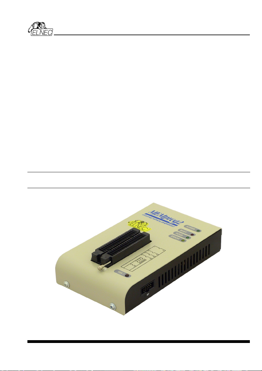
MEMprog2
MEMprog2
51
Page 52

Introduction
MEMprog2 is next member of new generation of Windows based ELNEC specialized
programmers. Programmer is built to meet the demands of the development labs and field
engineers for a specialized memory programmer.
MEMprog2 can be upgraded to SmartProg2 using Xprog2 to SmartProg2 upgrade kit
(ord.no.60-0048).
MEMprog2 is small, fast and powerful programmer for virtually all memory types - EPROM,
EEPROM, NVRAM, Flash EPROM and serial EEPROM - low voltage types including.
MEMprog2 isn't only programmer, but also static RAM tester.
MEMprog2 provides very competitive price with excellent hardware design for reliable
programming. Nice "value for money" in this class.
MEMprog2 provides very fast programming due to high-speed FPGA driven hardware and
USB 2.0 full speed port.
MEMprog2 interfaces with the IBM PC Pentium compatible or higher, portable or desktop
personal computers through USB port, what is important for new, LPT-port-less computers
(notebooks for example).
MEMprog2 has 40 powerful TTL pindrivers provide H/L/pull_up/pull_down and read
capability for each pin of socket. Advanced pindrivers incorporate high-quality high-speed
circuitry to deliver signals without overshoot or ground bounce for all supported devices. Pin
drivers operate down to 1.8V so you'll be ready to program the full range of today's advanced
low-voltage devices.
The programmer performs device insertion test (wrong device position in socket) and
contact check (poor contact pin-to-socket) before it programs each device. These
capabilities, supported by signature-byte check help prevent chip damage due to operator
error.
MEMprog2 performs programming verification at the marginal level of supply voltage,
which, obviously, improves programming yield, and guarantees long data retention.
MEMprog2 is driven by an easy-to-use control program with pull-down menus, hot keys and
on-line help. Selecting of device is performed by its class, by manufacturer or simply by
typing a fragment of vendor name and/or part number.
Standard device-related commands (read, blank check, program, verify, erase) are
enhanced by some test functions (insertion test, signature-byte check), and some special
functions (autoincrement).
All known data formats are supported. Automatic file format detection and conversion during
load of file.
ELNEC s. r. o.
52
Page 53

The rich-featured autoincrement function enables to assign individual serial numbers to
each programmed device - or simply increments a serial number, or the function enables to
read serial numbers or any programmed device identification signatures from a file.
The software also provides a lot of information about programmed device. As a special, the
drawings of all available packages, explanation of chip labeling (the meaning of prefixes
and suffixes at the chips) for each supported chip are provided.
Various socket converters are available to handle device in PLCC, SOIC, SSOP, TSOP,
TSSOP and other packages.
MEMprog2 elements
1) 40 pin ZIF socket
2) power/sleep LED
3) work result LEDs
4) YES! Button
5) Connector for ISP (useable after upgrade to SmartProg2 only, details: see SmartProg2)
MEMprog2
6) USB connector for PC ↔ MEMprog2 communication cable
7) Power supply connector
53
Page 54

ELNEC s. r. o.
Power supply connector
+
Connecting MEMprog2 to PC
For MEMprog2 order of connecting USB cable and power supply to programmer is irrelevant.
Problems related to the MEMprog2 PC interconnection, and
their removing
If you have any problems with MEMprog2 PC interconnection, see section Common
notes please.
Manipulation with the programmed device
After selection of desired device for your work, you can insert into the open ZIF socket (the
lever is up) and close socket (the lever is down). The correct orientation of the programmed
device in ZIF socket is shown on the picture near ZIF socket on the programmer's cover. The
programmed device is necessary to insert into the socket also to remove from the socket
when LED BUSY light off.
Warning: MEMprog2 programmer hasn’t protection devices, which protect the content of
programmed device against critical situations, for example power failures and PC failure
(interrupted cable...). Moreover, a device is usually destroyed in the programming mode due
to forced interruption of the control program run (Reset or switching the computer off) due to
removing the connecting cable, or unplugging the programmed device from the ZIF socket.
Incorrectly placed device in the ZIF socket can cause its damage or destruction.
Selftest
If you feel that your programmer does not react according to your expectation, please run the
programmer selftest using Diagnostic POD, enclosed with the standard delivery package.
• Insert 40 pins diagnostic POD - type I into ZIF socket of the programmer. 40 pins
diagnostic POD - type I must be inserted as 40 pins device.
• Run selftest of programmer in Pg4uw (Programmer / Selftest plus).
54
Page 55

Technical specification
HARDWARE
Programmer
• two D/A converters for VCCP and VPP, controllable rise and fall time
• VCCP range 0..7V/350mA
• VPP range 0..25V/200mA
• USB 2.0/1.1 compatible interface
• selftest capability
ZIF socket, pindriver
• 40-pin DIL ZIF (Zero Insertion Force) socket accepts both 300/600 mil devices up to 40-pins
• pindriver: 40 TTL pindrivers, specialized GND/VCC/VPP pindriver
• FPGA based TTL driver provides H, L, CLK, pull-up, pull-down on all pindriver pins, level H
selectable from 1.8 V up to 5V
• continuity test: each pin is tested before every programming operation
ISP connector (useable after upgrade to SmartProg2 only)
• 10-pin male type with miss insertion lock
• 6 TTL pindrivers, provides H, L, CLK, pull-up, pull-down; level H selectable from 1.8V up to
5V to handle all (low-voltage including) devices.
• 1x VCCP voltage (range 2V..7V/100mA) and 1x VPP voltage (range 2V..25V/50mA)
• programmed chip voltage (VCCP) with both source/sink capability and voltage sense
MEMprog2
DEVICE SUPPORT
Programmer
• EPROM: NMOS/CMOS, 2708(*3), 27xxx and 27Cxxx series, with 8/16 bit data width, full
support of LV series (*1*2)
• EEPROM: NMOS/CMOS, 28xxx, 28Cxxx, 27EExxx series, with 8/16 bit data width, full
support of LV series (*1*2)
• Flash EPROM: 28Fxxx, 29Cxxx, 29Fxxx, 29BVxxx, 29LVxxx, 29Wxxx, 49Fxxx series, with
8/16 bit data width, full support of LV series (*1*2)
• Serial E(E)PROM: 24Cxxx, 24Fxxx, 25Cxxx, 45Dxxx, 59Cxxx, 25Fxxx, 25Pxxx, NVM3060,
MDA206x (*3), 85xxx, 93Cxxx, full support for LV series (*1)
• Configuration (EE)PROM: 37LVxx, XC17xxxx, AT17xxx, LV series including (*1)
• NV RAM: Dallas DSxxx, SGS/Inmos MKxxx, SIMTEK STKxxx, XICOR 2xxx, ZMD U63x
series
Notes:
• (*1) - suitable adapters are available for non-DIL packages
• (*2) - there exist only few adapters for devices with more than 40 pins. Therefore think
please about more powerful programmer(BeeProg2 / BeeProg+), if you need to program
devices with more than 40 pins
• (*3) - programming with additional module
55
Page 56

• For all supported devices see actual Device list on www.elnec.com.
I.C. Tester
• Static RAM: 6116..624000
Programming speed
Device Operation Mode Time
27C010 programming and verify in ZIF 24 sec
AT29C040A programming and verify in ZIF 32 sec
AM29F040 programming and verify in ZIF 69 sec
Conditions: P4, 2,4GHz, USB 2.0 HS, Windows XP
SOFTWARE
• Algorithms: only manufacturer approved or certified algorithms are used.
• Algorithm updates: software updates are available approx. every 2 weeks, free of charge.
• Main features: revision history, session logging, on-line help, device and algorithm
information
Device operations
• standard:
• intelligent device selection by device type, manufacturer or typed fragment of part name
• blank check, read, verify
• program
• erase
• illegal bit test
• checksum
• security
• insertion test
• contact check
• ID byte check
• special
• auto device serial number increment
• statistic
• count-down mode
ELNEC s. r. o.
Buffer operations
• view/edit, find/replace
• fill, copy, move, byte swap, word/dword split
• checksum (byte, word)
• print
File load/save
• no download time because programmer is PC controlled
• automatic file type identification
56
Page 57

Supported file formats
• unformatted (raw) binary
• HEX: Intel, Intel EXT, Motorola S-record, MOS, Exormax, Tektronix, ASCII-SPACE-HEX
GENERAL
• operating voltage 15..20V DC, max. 500mA
• power consumption max. 6W active, 1.4W inactive
• dimensions 160x97x35 mm (6.3x3.8x1.4 inch)
• weight (without external power adapter) ca. 500g (17.65 oz)
• operating temperature 5°C ÷ 40°C (41°F ÷ 104°F)
• operating humidity 20%..80%, non condensing
MEMprog2
57
Page 58

ELNEC s. r. o.
T51prog2
58
Page 59

Introduction
T51prog2 is next member of new generation of Windows based ELNEC specialized
programmers. Programmer is capable to support all today available microcontrollers of
MCS51 series (up to 40 pins) and AVR microcontrollers (8-40 pins) by parallel and serial way.
T51prog2 has been developed in close cooperation with Atmel W&M, therefore programmer's
hardware is focused to support all current and future microcontrollers of Atmel W&M MCS51
family.
T51prog2 can be upgraded to SmartProg2 using Xprog2 to SmartProg2 upgrade kit
(ord.no.60-0048).
T51prog2 is small, fast and powerful programmer for MCS51 series and Atmel AVR
microcontrollers. T51prog2 enables also programming of serial EEPROM with IIC (24Cxx),
Microwire (93Cxx) and SPI (25Cxx) interface types. Using build-in in-circuit serial
programming (ISP) connector programmer is capable to program MCS51 family
microcontrollers and Atmel AVR microcontrollers in serial way.
T51prog2 provides very competitive price but excellent hardware design for reliable
programming. Nice "value for money" in this class.
T51prog2 provides very fast programming due to high-speed FPGA driven hardware and
USB 2.0 full speed port.
T51prog2 interfaces with the IBM PC Pentium compatible or higher, portable or desktop
personal computers through USB port, what is important for new, LPT-port-less computers
(notebooks for example).
T51prog2 has 40 powerful TTL pindrivers provide H/L/pull_up/pull_down and read capability
for each pin of socket. Advanced pindrivers incorporate high-quality high-speed circuitry to
deliver programming without overshoot or ground bounce for all supported devices. Pin
drivers operate down to 1.8V so you'll be ready to program the full range of today's advanced
low-voltage devices.
The programmer performs device insertion test (wrong or backward position) and contact
check (poor contact pin-to-socket) before it programs each device. These capabilities,
supported by signature-byte check help prevent chip damage due to operator error.
T51prog2 performs programming verification at the marginal level of supply voltage, which,
obviously, improves programming yield, and guarantees long data retention
T51prog2 programmer is driven by an easy-to-use control program with pull-down menu, hot
keys and on-line help. Selecting of device is performed by its class, by manufacturer or
simply by typing a fragment of vendor name and/or part number.
Standard device-related commands (read, blank check, program, verify, erase) are boosted
by some test functions (insertion test, signature-byte check), and some special functions
(autoincrement).
T51prog2
59
Page 60

All known data formats are supported. Automatic file format detection and conversion during
load of file.
The rich-featured autoincrement function enables to assign individual serial numbers to
each programmed device - or simply increments a serial number, or the function enables to
read serial numbers or any programmed device identification signatures from a file.
The software also provides a lot of information about programmed device. As a special, the
drawings of all available packages, explanation of chip labeling (the meaning of prefixes
and suffixes at the chips) for each supported chip are provided.
Various socket converters are available to handle device in PLCC, SOIC, SSOP, TSSOP,
TQFP, QFN (MLF) and other packages.
T51prog2 elements
1) 40 pin ZIF socket
2) power/sleep LED
3) work result LEDs
4) YES! Button
5) Connector for ISP
ELNEC s. r. o.
6) USB connector for PC ↔ T51prog2 communication cable
7) Power supply connector
60
Page 61

T51prog2
Power supply connector
+
Connecting T51prog2 to PC
For T51prog2 order of connecting USB cable and power supply to programmer is irrelevant.
Problems related to the T51prog2 PC interconnection, and
their removing
If you have any problems with T51prog2 PC interconnection, see section Common
notes please.
Manipulation with the programmed device
After selection of desired device for your work, you can insert into the open ZIF socket (the
lever is up) and close socket (the lever is down). The correct orientation of the programmed
device in ZIF socket is shown on the picture near ZIF socket on the programmer's cover. The
programmed device is necessary to insert into the socket also to remove from the socket
when LED BUSY light off.
Warning: T51prog2 programmer hasn’t protection devices, which protect the content of
programmed device against critical situations, for example power failures and PC failure
(interrupted cable...). Moreover, a device is usually destroyed in the programming mode due
to forced interruption of the control program run (Reset or switching the computer off) due to
removing the connecting cable, or unplugging the programmed device from the ZIF socket.
Incorrectly placed device in the ZIF socket can cause its damage or destruction.
In-System serial programming by T51prog2
For general definition, recommendation and direction about ISP see section Common notes
/ ISP please.
Description of T51prog2 ISP connector
6
8910
234
5
7
1
Front view at ISP connector of programmer.
Specification of ISP connector pins depends on the device, which you want to program. You
can find it in the control SW for programmer (Pg4uw), menu Device / Device Info (Ctrl+F1).
Be aware, the ISP programming way of respective device must be selected. It is indicated by
(ISP) suffix after name of selected device.
61
Page 62

These specifications correspond with Atmel application note AVR910: In-System
Programming. Used application note you may find on
www.elnec.com, section Support /
Application Notes.
Note: Pin no. 1 is signed by triangle scratch on ISP cable connectors.
ELNEC s. r. o.
ISP cable of T51prog2
Warnings:
• When you use T51prog2 as ISP programmer, don’t insert device to ZIF socket.
• When you program devices in ZIF socket, don’t insert ISP cable to ISP connector.
• Use only attached ISP cable. When you use other ISP cable (other material, length…),
programming may occur unreliable.
• T51prog2 cannot supply target system and target system cannot supply T51prog2.
Before action with target device T51prog2 check power supply of target system. If this
power supply is different as expected, no action with device will be executed.
Note: H/L/read T51prog2 driver.
C1
H/L/read driver
in programmer
PU/PD driver
in programmer
C1=1nF, R1=1k3, R2=22k
R1
R2
pin of ISP
connector
Selftest
If you feel that your programmer does not react according to your expectation, please run the
programmer selftest using Diagnostic POD, enclosed with the standard delivery package.
• Insert 40 pins diagnostic POD - type I into ZIF socket of the programmer. 40 pins
diagnostic POD - type I must be inserted as 40 pins device.
• Run selftest of programmer in Pg4uw (Programmer / Selftest plus).
62
Page 63

Technical specification
HARDWARE
Socket, pin drivers and DACs
• two D/A converters for VCCP and VPP, controllable rise and fall time
• VCCP range 0..7V/350mA
• VPP range 0..25V/200mA
• USB 2.0/1.1 compatible interface
• selftest capability
ZIF socket, pindriver
• 40-pin DIL ZIF (Zero Insertion Force) socket accepts both 300/600 mil devices up to 40-pins
• pindriver: 40 TTL pindrivers, universal GND/VCC/VPP pindriver
• FPGA based TTL driver provides H, L, CLK, pull-up, pull-down on all pindriver pins, level H
selectable from 1.8 V up to 5V
• continuity test: each pin is tested before every programming operation
ISP connector
• 10-pin male type with miss insertion lock
• 6 TTL pindrivers, provides H, L, CLK, pull-up, pull-down; level H selectable from 1.8V up to
5V to handle all (low-voltage including) devices.
• 1x VCCP voltage (range 2V..7V/100mA) and 1x VPP voltage (range 2V..25V/50mA)
• programmed chip voltage (VCCP) with both source/sink capability and voltage sense
T51prog2
DEVICE SUPPORT
Programmer, in ZIF socket
• microcontrollers MCS51 series: 87Cxxx, 87LVxx, 89Cxxx, 89Sxxx, 89LVxxx, LPC series
from Atmel, Atmel W&M, Intel, Philips, SST, Winbond, ... 8-40 pins (*1)
• microcontrollers Atmel AVR: ATtiny, AT90Sxxx, ATmega series (parallel and serial mode),
8-40 pins (*1)
• Serial E(E)PROM: 24Cxxx, 24Fxxx, 25Cxxx, 59Cxxx, 85xxx, 93Cxxx series
Programmer, through ISP connector
• Microcontrollers Atmel: AT89Sxxx, AT90Sxxxx, ATtiny, ATmega series
• Microcontrollers Philips: LPC series
Note:
For all supported devices see actual Device list on
www.elnec.com.
Programming speed
Device Operation Time
AT89C52 programming and verify 17 sec
Conditions: P4, 2,4GHz, USB 2.0 HS, Windows XP
T87C5111 programming and verify 14 sec
63
Page 64

SOFTWARE
• Algorithms: only manufacturer approved or certified algorithms are used.
• Algorithm updates: software updates are available approx. every 4 weeks, free of charge.
• Main features: revision history, session logging, on-line help, device and algorithm
information
Device operations
• standard:
• intelligent device selection by device type, manufacturer or typed fragment of part name
• blank check, read, verify
• program
• erase
• illegal bit test
• checksum
• security
• insertion test
• contact check
• ID byte check
• special
• auto device serial number increment
• statistic
• count-down mode
Buffer operations
• view/edit, find/replace
• fill/copy, move, byte swap, word/dword split
• checksum (byte, word)
• print
ELNEC s. r. o.
File load/save
• no download time because programmer is PC controlled
• automatic file type identification
Supported file formats
• unformatted (raw) binary
HEX: Intel, Intel EXT, Motorola S, MOS, Exormax, Tektronix, ASCII-space-HEX
GENERAL
• operating voltage 15..20V DC, max. 500mA
• power consumption max. 6W active, 1.4W inactive
• dimensions 160x97x35 mm (6.3x3.8x1.4 inch)
• weight (without external power adapter) ca. 500g (17.65 oz)
• operating temperature 5°C ÷ 40°C (41°F ÷ 104°F)
• operating humidity 20%..80%, non condensing
64
Page 65

PIKprog2
PIKprog2
65
Page 66

Introduction
ELNEC s. r. o.
PIKprog2 is next member of the new generation of Windows based ELNEC specialized
programmers. Programmer is capable to support all currently available Microchip
PICmicro
®
series microcontrollers (8-40 pins) using parallel and serial algorithms. The
TM
PIKprog2 programmer isn't development grade programmer, but meets all Microchip's
requirements to manufacturing grade of programmers. The PIKprog2 has been developed in
close cooperation with Microchip
support all current and future PICmicro
TM
Company therefore programmer's hardware is focused to
®
family microcontrollers.
PIKprog2 can be upgraded to SmartProg2 using Xprog2 to SmartProg2 upgrade kit
(ord.no.60-0048).
PIKprog2 is a small, fast and powerful programmer for PICmicro
®
family microcontrollers and
serial EEPROM with IIC (24Cxx), Microwire (93Cxx) and SPI (25Cxx) interface types. Using
build-in in-circuit serial programming (ISP) connector programmer is able to program
PICmicro
®
family microcontrollers using serial algorithms.
PIKprog2 provides very competitive price but excellent hardware design for reliable
programming. Nice "value for money" in this class.
PIKprog2 provides very fast programming due to high-speed FPGA driven hardware and
USB 2.0 full speed port.
PIKprog2 interfaces with the IBM PC Pentium compatible or higher, portable or desktop
personal computers through USB port, what is important for new, LPT-port-less computers
(notebooks for example).
PIKprog2 has 40 powerful TTL pindrivers provide H/L/pull_up/pull_down and read capability
for each pin of socket. Advanced pindrivers incorporate high-quality high-speed circuitry to
deliver signals without overshoot or ground bounce for all supported devices. Pin drivers
operate down to 1.8V so you'll be ready to program the full range of today's advanced lowvoltage devices.
The programmer performs device insertion test (wrong device position in socket) and
contact check (poor contact pin-to-socket) before it programs each device. These
capabilities, supported by signature-byte check help prevent chip damage due to operator
error.
PIKprog2 programmer performs programming verification at the marginal level of supply
voltage, which, obviously, improves programming yield, and guarantees long data retention.
PIKprog2 programmer is driven by an easy-to-use control program with pull-down menu, hot
keys and on-line help. Selecting of device is performed by its class, by manufacturer or
simply by typing a fragment of vendor name and/or part number.
Standard device-related commands (read, blank check, program, verify, erase) are boosted
by some test functions (insertion test, signature-byte check), and some special functions
(autoincrement).
66
Page 67

All known data formats are supported. Automatic file format detection and conversion during
load of file.
The rich-featured autoincrement function enables to assign individual serial numbers to
each programmed device - or simply increments a serial number, or the function enables to
read serial numbers or any programmed device identification signatures from a file.
The software also provides a lot of information about programmed device. As a special, the
drawings of all available packages, explanation of chip labeling (the meaning of prefixes
and suffixes at the chips) for each supported chip are provided.
Various socket converters are available to handle device in PLCC, SOIC, SSOP, TSSOP,
TQFP and other packages.
PIKprog2 elements
1) 40 pin ZIF socket
2) power/sleep LED
3) work result LEDs
4) YES! Button
5) Connector for ISP
PIKprog2
6) USB connector for PC ↔ PIKprog2 communication cable
7) Power supply connector
67
Page 68

ELNEC s. r. o.
Power supply connector
+
Connecting PIKprog2 programmer to PC
For PIKprog2 order of connecting USB cable and power supply to programmer is irrelevant.
Problems related to the PIKprog2 PC interconnection, and
their removing
If you have any problems with PIKprog2 PC interconnection, see section Common
notes please.
Manipulation with the programmed device
After selection of desired device for your work, you can insert into the open ZIF socket (the
lever is up) and close socket (the lever is down). The correct orientation of the programmed
device in ZIF socket is shown on the picture near ZIF socket on the programmer's cover. The
programmed device is necessary to insert into the socket also to remove from the socket
when LED BUSY light off.
Warning! PIKprog2 programmer hasn’t protection devices, which protect the content of
programmed device against critical situations, for example power failures and PC failure
(interrupted cable...). Moreover, a device is usually destroyed in the programming mode due
to forced interruption of the control program run (Reset or switching the computer off) due to
removing the connecting cable, or unplugging the programmed device from the ZIF socket.
Incorrectly placed device in the ZIF socket can cause its damage or destruction.
In-System serial programming by PIKprog2
For general definition, recommendation and direction about ISP see section Common notes
/ ISP please.
Description of PIKprog2 ISP connector
6
8910
234
5
7
1
Specification of ISP connector pins depends on the device, which you want to program. You
can find it in the control SW for programmer (Pg4uw), menu Device / Device Info (Ctrl+F1).
Be aware, the ISP programming way of respective device must be selected. It is indicated by
(ISP) suffix after name of selected device.
Front view at ISP connector of programmer.
68
Page 69

These specifications correspond with Microchip application note: In-Circuit Serial
Programming™ (ICSP™) Guide. Used application note you may find on
www.elnec.com,
section Support / Application Notes.
Note: Pin no. 1 is signed by triangle scratch on ISP cable connectors.
PIKprog2
ISP cable of PIKprog2
Warnings:
• When you use PIKprog2 as ISP programmer, don’t insert device to ZIF socket.
• When you program devices in ZIF socket, don’t insert ISP cable to ISP connector.
• Use only attached ISP cable. When you use other ISP cable (other material, length…),
programming may occur unreliable.
• PIKprog2 can supply programmed device only, but target system cannot supply
PIKprog2.
• PIKprog2 apply programming voltage to target device and checks his value (target system
can modify programming voltage). If the programming voltage is different as expected, no
action with target device will be executed.
Note: H/L/read PIKprog2 driver
C1
H/L/read driver
in programmer
PU/PD driver
in programmer
C1=1nF, R1=1k3, R2=22k
R1
R2
pin of ISP
connector
Selftest
If you feel that your programmer does not react according to your expectation, please run the
programmer selftest using Diagnostic POD, enclosed with the standard delivery package.
• Insert 40 pins diagnostic POD - type I into ZIF socket of the programmer. 40 pins
diagnostic POD - type I must be inserted as 40 pins device.
• Run selftest of programmer in Pg4uw (Programmer / Selftest plus).
69
Page 70

Technical specification
HARDWARE
Socket, pin drivers and DACs
• two D/A converters for VCCP and VPP, controllable rise and fall time
• VCCP range 0..7V/350mA
• VPP range 0..25V/200mA
• USB 2.0/1.1 compatible interface
• selftest capability
ZIF socket, pindriver
• 40-pin DIL ZIF (Zero Insertion Force) socket accepts both 300/600 mil devices up to 40-pins
• pindriver: 40 TTL pindrivers, universal GND/VCC/VPP pindriver
• FPGA based TTL driver provides H, L, CLK, pull-up, pull-down on all pindriver pins, level H
selectable from 1.8 V up to 5V
• continuity test: each pin is tested before every programming operation
ISP connector
• 10-pin male type with miss insertion lock
• 6 TTL pindrivers, provides H, L, CLK, pull-up, pull-down; level H selectable from 1.8V up to
5V to handle all (low-voltage including) devices.
• 1x VCCP voltage (range 2V..7V/100mA) and 1x VPP voltage (range 2V..25V/50mA)
• programmed chip voltage (VCCP) with both source/sink capability and voltage sense
ELNEC s. r. o.
DEVICE SUPPORT
Programmer, in ZIF socket
• microcontrollers MicrochipTM PICmicro®: PIC10xxx, PIC12xxx, PIC14xxx, PIC16xxx,
PIC17xxx, PIC18xxx, dsPIC series, 8 to 40 pins (*1)
• Serial E(E)PROM: 17Cxxx, 24Cxxx, 24Fxxx, 25Cxxx, 59Cxxx, 85xxx, 93Cxxx series
Programmer, through ISP connector
• Microcontrollers Microchip PICmicro: PIC10xxx, PIC12xxx, PIC16xxx, PIC17xxx, PIC18xxx,
dsPIC series
Notes:
• (*1) - suitable adapters are available for non-DIL packages and devices with more than 40
pins
• For all supported devices see actual Device list on
70
www.elnec.com.
Page 71

Programming speed
Device Operation Mode Time A
PIC16C67 programming and verify in ZIF 12 sec
PIC18F452 programming and verify in ZIF 8 sec
PIC16F876A programming and verify ISP 5 sec
PIC12C508 programming and verify ISP 3 sec
Conditions: P4, 2,4GHz, USB 2.0 HS, Windows XP
SOFTWARE
• Algorithms: only manufacturer approved or certified algorithms are used.
• Algorithm updates: software updates are available approx. every 2 weeks, free of charge.
• Main features: revision history, session logging, on-line help, device and algorithm
information
Device operations
• standard:
• intelligent device selection by device type, manufacturer or typed fragment of part name
• blank check, read, verify
• program
• erase
• configuration and security bit program
• illegal bit test
• checksum
• security
• insertion test
• contact check
• ID byte check
• special
• auto device serial number increment
• statistic
• count-down mode
PIKprog2
Buffer operations
• view/edit, find/replace
• fill, copy, move, byte swap, word/dword split
• checksum (byte, word)
• print
File load/save
• no download time because programmer is PC controlled
• automatic file type identification
Supported file formats
• unformatted (raw) binary
71
Page 72

• HEX: Intel, Intel EXT, Motorola S-record, MOS, Exormax, Tektronix, ASCII-SPACE-HEX
GENERAL
• operating voltage 15..20V DC, max. 500mA
• power consumption max. 6W active, 1.4W inactive
• dimensions 160x97x35 mm (6.3x3.8x1.4 inch)
• weight (without external power adapter) ca. 500g (17.65 oz)
• operating temperature 5°C ÷ 40°C (41°F ÷ 104°F)
• operating humidity 20%..80%, non condensing
ELNEC s. r. o.
72
Page 73

SEEprog
SEEprog
73
Page 74

Introduction
SEEprog is universal programmer of all serial EEPROM in 8-pin DIL package. SEEprog
programs EEPROM with interface IIC, SPI and Microwire, and also specialty as for example
digital thermometers. The programmer supports LV (3.3V) devices too.
SEEprog interfaces with the IBM PC Pentium compatible or higher, portable or desktop
personal computers. Programmer allows you to directly connect to your PC through any
standard parallel (printer) port - no special interface card is needed.
SEEprog programmer is driven by an easy-to-use control program with pull-down menu, hot
keys and on-line help. Selecting of device is performed by its class, by manufacturer or
simply by typing a fragment of vendor name and/or part number.
Standard device-related commands (read, blank check, program, verify, erase) are boosted
by some test functions, and some special functions (autoincrement).
All known data formats are supported. Automatic file format detection and conversion during
load of file.
The rich-featured autoincrement function enables to assign individual serial numbers to
each programmed device - or simply increments a serial number, or the function enables to
read serial numbers or any programmed device identification signatures from a file.
The software also provides a lot of information about programmed device. As a special, the
drawings of all available packages, explanation of chip labeling (the meaning of prefixes
and suffixes at the chips) for each supported chip are provided.
For SEEprog programmer are available DIL to SOIC socket converters.
ELNEC s. r. o.
74
Page 75

SEEprog elements
1) 14 pin ZIF socket. Only 8 bottommost pins are active, as shown at the picture at the left.
2) power LED
3) LPT connector for PC ↔ SEEprog communication cable
4) work result LED
5) Power supply connector
SEEprog
Power supply connector
+
Connecting SEEprog programmer to PC
Switch off the PC and programmer. Insert the connection cable, included in the SEEprog
programmer delivery, to the free printer port of PC. If your computer is equipped with only one
printer port, substitute the programmer cable for the printer cable. Connect the opposite cable
end to the programmer. Screw on both connectors to counter connectors. This is very
important mainly for the connector to programmer. Though replacing the printer cable by the
programmer cable is uncomfortable, it is not recommended to operate the SEEprog
programmer through a mechanical printer switch. Use of an electronic printer switch isn't
possible.
Connect the mains connector of the power supply (or wall-plug power supply self) to a mains
plug, connect the connector to the appropriate programmer's connector. Then, on the
programmer lights up LED POWER and the programmer SEEprog is ready to run. Next
switch on the PC and run the control program.
Caution! If you don't want to switch off your PC when connecting the SEEprog, proceed as
follows:
75
Page 76

ELNEC s. r. o.
• When connecting the programmer to the PC: FIRST insert the communications cable
and THEN the power-supply connector.
• When disconnecting the programmer from the PC: FIRST disconnect the power-supply
connector and THEN the communication cable.
Problems related to the SEEprog PC interconnection, and their
removing
The LPT port have to be set to SPP (standard parallel port) mode. In some cases BIOS of
computer don't allow to switch proper mode by software, therefore we recommend to do it
manually. If you have any problems with SEEprog PC interconnection, see section
Common notes please.
Manipulation with the programmed device
After selection of desired device for your work, you can insert into the open ZIF socket (the
lever is up) and close socket (the lever is down). The correct orientation of the programmed
device in ZIF socket is shown on the picture near ZIF socket on the programmer's. Only 8
bottommost pins of the DIL14 ZIF socket are active! The programmed device is
necessary to insert into the socket also to remove from the socket when LED BUSY light off.
Warning! SEEprog programmer hasn’t protection devices, which protect the content of
programmed device against critical situations, for example power failures and PC failure
(interrupted cable...). Moreover, a device is usually destroyed in the programming mode due
to forced interruption of the control program run (Reset or switching the computer off) due to
removing the connecting cable, or unplugging the programmed device from the ZIF socket.
Incorrectly placed device in the ZIF socket can cause its damage or destruction.
Technical specification
HARDWARE
Socket and control of pins:
• DIL/ZIF socket (300mil)
• each pin is possible to set in position Low and Pull-up
• from each pin is possible to read
• support of Low Voltage devices
For works with serial EEPROM are used nearest 8 pins to lever, unused pins are not
connected.
DEVICE SUPPORT
• EEPROM IIC (24Cxxx)
• EEPROM Microwire (93Cxxx)
• EEPROM SPI (25Cxxx)
• specially devices (digital thermometers, ...)
Note:
76
Page 77

• For all supported devices see actual Device list on www.elnec.com.
SOFTWARE
• Algorithms: only manufacturer approved or certified algorithms are used.
• Algorithm updates: software updates are available approx. every 4 weeks, free of charge.
• Main features: revision history, session logging, on-line help, device and algorithm
information
Device operations
• standard:
• blank check
• read
• program
• verify
• checksum
Buffer operations
• view/edit, find/replace
• fill/copy, move, byte swap, word/dword split
• checksum (byte, word)
• print
File format conversion
• binary
HEX: Intel, Intel EXT, Motorola S, MOS, Exormax, ASCII - space – HEX, Tektronix
SEEprog
GENERAL
• power supply: 8V...15V, max.50mA
• dimensions 137x65x40 mm (5.4x2.6x1.6 inch)
• weight (without external adapter and connecting cable) ca. 150g (5.295 oz)
• operating temperature 5°C ÷ 40°C (41°F ÷ 104°F)
• operating humidity 20%..80%, non condensing
77
Page 78

ELNEC s. r. o.
Setup
78
Page 79

The programmer package contains a CD with the control program, useful utilities and
additional information. The permission to freely copy the content of the CD is granted in order
to demonstrate how ELNEC programmers work.
For programmers connected through USB (LPT) port, control program requires correctly
installed USB driver
We recommended install software before connecting programmer to PC to avoid
unwanted complication during installation.
Software setup
Insert delivered CD to your CD drive and install program starts automatically (if not, run
setup.exe). Install program will guide you through the installation process and will do all the
necessary steps before you can first run the control program.
Step 1.
Setup
Step 2.
Click on “Software installation PROGRAMMERS” button.
Select language and than click on “OK” button.
79
Page 80

ELNEC s. r. o.
Step 3.
Click on “Next” button
Step 4.
For change default folder click on “Browse” button, select the destination folder.
Then click on “Next” button
80
Page 81

Setup
Step 5.
For change default folder click on “Browse” button, select the destination folder. Then click on
“Next” button
Step 6.
Check if “Install Multiprogramming control support” is selected.
Change default setting, if you want. Then click on “Next” button
81
Page 82

ELNEC s. r. o.
Step 7.
Check your setting and then click on “Install” button
Step 8.
Installation process will start.
82
Page 83

Step 9.
This window will be displayed for first time installation of current version of driver only.
Setup
Click on “Continue Anyway” button.
For Windows Vista:
Click “Install this driver software anyway”
83
Page 84

ELNEC s. r. o.
Step10.
Step 11.
For Windows Vista only:
Click “Finish” button to finish setup.
Click “This program installed correctly”
84
Page 85

New versions of programmer software
In order to exploit all the capabilities of programmer we recommend using the latest version
of Pg4uw. You may download the latest version of programmer software (file
Pg4uwARC.exe) from our Internet site
Copy Pg4uwARC.exe to a temporary directory, disconnect programmer from PC and then
launch it. Setup will start with Step 2 from previous chapter.
www.elnec.com, part download.
Hardware setup
When the programmer is connected to USB port before control program was installed,
Windows will detect new hardware and ask user to select driver installation method:
automatically or manually. To detect programmer correctly, control program installation CD
must be inserted to computer's CD-ROM drive and following steps have to be done:
Step 1.
Directly connect USB (LPT) cable to type B USB (LPT) port on programmer.
Step 2.
Directly connect USB (LPT) cable to type A USB2.0 (LPT) port on PC (high-speed
recommended).
Step 3.
Connect connectors of power supply cable to appropriate connectors on programmer and
wall plug.
Step 4.
Turn on programmer. At this time all 'work result' LEDs light up successive and then LEDs
switch off.
For LPT connected programmer you may start work with your programmer now.
For USB connected programmer continue with next step.
Setup
85
Page 86

Step 5.
Windows will start with “Found new hardware wizard”.
For Windows XP, Service Pack 2 users only:
ELNEC s. r. o.
Select “No, not this time” and then click on “Next” button.
For all:
Select “Install the software automatically” and then click on “Next” button.
86
Page 87

Setup
Step 6.
Click on “Continue Anyway” button.
For Windows Vista:
Click “Install this driver software anyway”
87
Page 88

ELNEC s. r. o.
Step 7.
Step 8.
Click “Finish” button to finish setup.
“Found new hardware wizard” will launch for each programmer one time (for BeeHive204 /
BeeHive4+ 4 times). Hardware setup will be continued with Step 5.
Note: If a different USB port on the PC is used for the next connection of programmer,
“Found new hardware wizard” will launch again and install new USB drivers.
88
Page 89

Pg4uw
Pg4uw
89
Page 90

Pg4uw-the programmer software
Program Pg4uw.exe is common control program for all ELNEC programmers. We guarantee
running of these programs under all of above mentioned operating systems without any
problems. Also background operation under Windows is error-free.
Using the programmer software
The control program delivered by ELNEC, included on the
CD in your package, is granted to be free from any viruses
at the moment of delivery. To increase their safety our
programs include a special algorithm for detecting possible
virus infections.
Run the control program
In Windows environment: double click to icon Pg4uw.
After start, control program Pg4uw automatically scan all existing ports and search for the
connected any ELNEC programmer. Program Pg4uw is common for all the ELNEC
programmers, hence program try to find all supported programmers.
Notes: When Pg4uw is started, program is checked for its integrity. Than the program display
a standard user menu and waits for your instructions.
If the control program cannot communicate with the programmer, an error message appears
on the screen, including error code and description of possible reasons (disconnected
programmer, bad connection, power supply failure, incompatible printer port...). Eliminate the
error source and press any key. If error condition still exists, the program resumes its
operation in the demo mode and access to the programmer is not possible. If you cannot find
the cause of the error, follow the instructions in Troubleshooting section. In addition, the
control program checks communication with programmer prior to any operation with the
programmed device.
ELNEC s. r. o.
90
Page 91
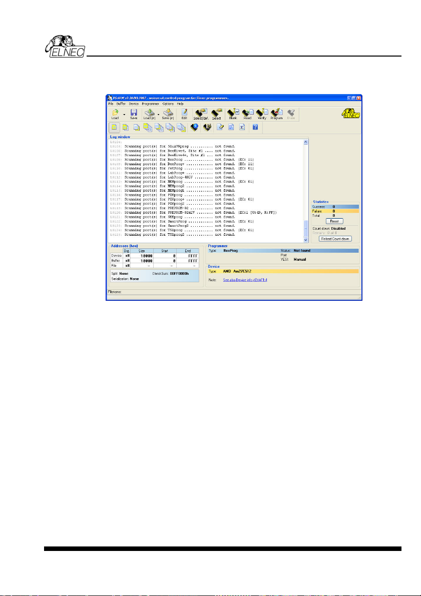
Description of the user screen
Windows program Pg4uw
Pg4uw
Toolbars
Under main menu are placed toolbars with button shortcuts of frequently used menu
commands. Toolbars are optional and can be turned off by menu command Options / View.
Log window
Log window contains the flow-control progress information about almost every operation
made in Pg4uw.
Operation can be:
• starting of Pg4uw
• programmer search
• file/project load/save
• selection of device
• device operations (device read, blank check, programming, ...)
• remote control application connection and disconnection
• and other
Content of Log window can be saved to file concurrently while information is written to Log
window. This option can be set by menu Options / General options (and tab Log file in
dialog General options).
Panel Addresses
Panel Addresses contains information about actual address ranges of currently selected
device, loaded file and buffer start-end address settings. Some devices allow modifying
default device and buffer address ranges by menu command Device / Device options /
Operation options.
91
Page 92

Panel Addresses also contains some advanced information about current status of Split,
Serialization and buffer checksum. For more information about each of the options, please
look at:
• Split - menu Device / Device options / Operation options
• Serialization - menu Device / Device options / Serialization
• Checksum - menu Buffer / Checksum at section Checksum displayed in main window
Panel Programmer
Panel Programmer contains information about currently selected programmer.
The information includes
• programmer type
• port via programmer is connected to computer
• programmer status, can be one of following
• Ready - programmer is connected, successfully found and ready to work
• Not found - programmer is not found
• Demo - when user selects option (button) Demo in dialog Find programmer
• YES! mode - some types of programmers allow to use special modes of starting next
device operation in one of following ways -
• manually by control program dialog Repeat
• manually by button YES! placed directly on programmer
• automatically - programmer automatically detects device removing and insertion of
new device
For more details please look at Programmer / Automatic YES!.
Panel Device
It contains information about currently selected device.
The information includes
• device name (type) and manufacturer
• device adapter needed to use with currently selected programmer
• reference to detailed Device info dialog, available also by menu Device / Device info
• reference to Advanced device options - this is available for some types of devices only
Panel Statistics
It contains statistics information about currently selected device.
The information includes
• number of successful, failure and total device operations
• count-down status indicating number of remaining devices
Statistics and count-down options are available by menu command Device / Device options
/ Statistics or by mouse right click on panel Statistics and select item Statistics from popup
menu
Panel File
The panel is placed on the bottom of Pg4uw main window. Panel shows currently loaded file
or project name, size and date.
ELNEC s. r. o.
92
Page 93

List of hot keys
<F1> Help Calls Help
<F2> Save Save file
<F3> Load Load a file into the buffer
<F4> Edit Viewing/editing of buffer
<F5> Select/default Target-device selection from 10 last selected devices list
<Alt+F5> Select/manual Target-device selection by typing device/vendor name
<F6> Blank Blank check
<F7> Read Reads device's content into the buffer
<F8> Verify Compares contents of the target device with the buffer
<F9> Program Programs target device
<Alt+Q> Exit without save Terminates the Pg4uw
<Alt+X> Exit and save Terminates the Pg4uw and saving settings too
<Ctrl+F1> Displays additional information about current device
<Ctrl+F2> Erase Fill's the buffer with a given value
<Ctrl+Shift+F2> Fill's the buffer with random values.
File
Menu File is used for source files manipulation, settings and viewing directory, changes
drives, changes start and finish address of buffer for loading and saving files by binary,
MOTOROLA, MOS Technology, Intel (extended) HEX, Tektronix, ASCII space, JEDEC,
and POF format. The menu commands for loading and saving projects are located in this
submenu too.
File / Load
Analyse file format and loads the data from specified file to the buffer. You can choose the
format desired (binary, MOTOROLA, MOS Technology, Tektronix, Intel (extended) HEX,
ASCII space, JEDEC and POF). The control program stores a last valid mask for file listing.
You can save the mask into the config. file by command Options / Save options.
The reserved key <F3> will bring out this menu from any menu and any time.
Note for special x16 formats:
Intel HEXx16 is Intel Hex file format with 16 bits data word for TMS320F devices.
Motorola HEXx16 is Motorola file format with 16 bits data word for TMS320F devices.
Checking the check box Automatic file format recognition tells program to detect file format
automatically. When program can't detect file format from one of supported formats, the
binary file format is assumed.
When the check box Automatic file format recognition is unchecked program allows user
to manually select wished file format from list of available file formats on panel Selected file
format. Default set is from Options / General options in panel Load file format at tab File
options.
Attention: Program doesn't know recognize files in ASCII Hex format automatically, it
recognizes them as binary. So download files in ASCII Hex format with disabled option for
automatic file format recognition.
Pg4uw
93
Page 94

Panel Additional operation
Checking the check box Erase buffer before loading tells the program to erase all buffer
data using entered Erase value. Buffer erase is performed immediately before reading file
content to buffer and it is functional for binary and all HEX file formats. Using this one-shot
setting disables current setting of Erase buffer before loading option in menu Options /
General options at tab Hex file options.
If the checkbox Swap bytes is displayed, the user can activate function of swapping bytes
within 16bit words (or 2-byte words) during reading of file. This feature is useful especially
when loading files with Motorola representation of byte order in file (big endian). Standard
load file is using little endian byte order.
Note: Big-endian and little-endian are terms that describe the order in which a sequence of
bytes are stored in computer memory. Big-endian is an order in which the "big end" (most
significant value in the sequence) is stored first (at the lowest storage address). Little-endian
is an order in which the "little end" (least significant value in the sequence) is stored first. For
example, in a big-endian computer, the two bytes required for the hexadecimal number 4F52
would be stored as 4F52H in storage address 1000H as: 4FH is stored at storage address
1000H, and 52H will be at address 1001H. In a little-endian system, it would be stored as
524FH (52H at address 1000H, and 4FH at address 1001H).
Number 4F52H is stored in memory:
Address Big endian system Little endian system
1000H 4FH 52H
1001H 52H 4FH
Panel Buffer offset for loading
Panel Buffer offset for loading contains one-shot offset setting for loading data from file to
buffer. The setting is used to specify optional offset of loaded data to store to buffer. When
Load file dialog window is opened, offset has always default setting None. It means, no offset
is used to store read data in buffer.
Available offset options are:
None this setting means, no offset is applied for loading data from file to buffer.
Positive offset set of offset value, which is added to current address to store data to buffer.
This offset is available for all formats and is used in x8 format, if current
buffer organization is x8, or in x16 format, if current buffer organization is
x16.
Negative offset mode has two options:
Negative offset and Automatic negative offset - set by two ways: manual or automatic.
For manual set use option Negative offset and put wished offset value to its edit box.
For automatic offset detection use option Automatic negative offset. This value is subtracted
from current address for save data to buffer.
Negative offset value (manually defined or automatically detected) is subtracted from current
buffer address for store data to buffer.
Negative offset is applied only for all HEX file formats and is using always x8 format. Negative
offset settings are ignored for binary files and other non-HEX files.
ELNEC s. r. o.
94
Page 95

Notes:
• Since the value of negative offset is subtracted from real address, the result of subtraction
can be negative number. Therefore take care of correct setting of this value!
• We recommend automatic set of negative offset in special cases only. This option
contains a heuristic analyze, which can treat some data in file incorrectly. There are
especially critical files, which contain a fragmented addresses range and which exceeds a
size of selected device - some block can be ignored.
• Automatic negative offset option is not available for some kinds of special devices, that
require HEX files with exactly specified blocks used for the devices - for example
Microchip PICmicro devices. For these special devices, there are available only manual
offset settings (None, Positive offset, Negative offset).
Example for negative offset using:
A file contains data by Motorola S - format.
A data block started at address FFFF0H.
It is a S2 format with length of address array of 3 bytes.
For all data reading you can set Negative offset option and value of negative offset to
FFFF0H.
It means, that the offset will be subtracted from current real addresses and so data will be
written from buffer address 0.
List of file format codes and error codes
There can occur some errors during file download in some of supported formats. The error is
written to LOG window in face "Warning: error #xxy in line rrr", xx is file format code, y is error
code and rrr is line number in decimal.
File format codes:
#00y - binary
#10y - ASCII Space
#20y - Tektronix
#30y - Extended Tektronix
#40y - Motorola
#50y - MOS Technology
#60y - Intel HEX
Load file error codes:
#xx1 - bad first character - header
#xx2 - bad character in current line
#xx3 - bad CRC
#xx4 - bad read address
#xx5 - bad length of current line
#xx6 - too big negative offset
#xx7 - address is out of buffer range
#xx8 - bad type of selected file format
#xx9 - the file wasn't loaded all
Pg4uw
File / Save
Saves data in the buffer, which has been created, modified, or read from a device onto a
specified disk. The file format of saved file can be chosen from supported formats list box.
95
Page 96

There can be also entered the Buffer start and Buffer end addresses which exactly specify
part of buffer to save to file. Supported file formats now are binary, MOTOROLA, MOS
Technology, Tektronix, Intel (extended) HEX, ASCII space, JEDEC and POF.
If the checkbox Swap bytes is displayed, the user can activate function of swapping bytes
within 16bit words (or 2-byte words) during writing to file. This feature is useful especially
when saving files with Motorola representation of byte order in file (big endian). Standard
save file operation is using little endian byte order.
The reserved key <F2> will bring out this menu from any menu and any time.
File / Load project
This option is used for loading project file, which contains device configuration buffer data
saved and user interface configuration.
The standard dialog Load project contains additional window - Project description - placed
at the bottom of dialog. This window is for displaying information about currently selected
project file in dialog Load project.
Project information consists of:
• manufacturer and name of the first device selected in the project
• date and time of project creation
• user written description of project (it can be arbitrary text, usually author of project and
some notes)
Note: for projects with serialization turned on
Serialization is read from project file by following procedure:
1. Serialization settings from project are accepted
2. Additional serialization file search is performed. If the file is found it will be read and
serialization settings from the additional file will be accepted. Additional serialization file
is always associated to the specific project file. When additional serialization file settings
are accepted, project serialization settings are ignored.
Name of additional serialization file is derived from project file name by adding extension ".sn"
to project file's name.
Additional serialization file is always placed to the directory "serialization\" into the control
program's directory.
Example:
Project file name: my_work.prj
Control program's directory: c:\Program Files\Programmer\
The additional serialization file will be:
c:\Program Files\Programmer\serialization\my_work.prj.sn
Additional serialization file is created and refreshed after successful device program
operation. The only requirement for creating additional serialization file is load project with
serialization turned on.
ELNEC s. r. o.
96
Page 97

Command File / Save project deletes additional serialization file, if the file exists, associated
with currently saved project.
File / Save project
This option is used for saving project file, which contains settings of device configuration and
buffer data saved. Data saved to project file can be restored anytime by menu command File
/ Load project.
The dialog Save project contains three additional windows in Project description panel
placed at the bottom of dialog Save project. The windows are for displaying information
about currently selected project file in dialog Save project and information about current
project, which has to be saved. Dialog Save project contains also additional checkboxes
and button with picture of key displayed.
The first checkbox named "Set Protected mode of software after loading of this project
file" and button with key are used to save project in special mode called Protected mode.
Clicking on the button with key displayed, password dialog appears which is used to specify
Protected mode password of recently saving project. Projects saved with active Protected
mode checkbox and password are special projects also called Protected mode projects. For
more detailed information about Protected mode projects see Options / Protected mode.
The second checkbox named "Require project file checksum before first programming"
has special function. When the checkbox is checked, program Pg4uw will ask user for
entering correct project checksum before allowing to start the first device programming. The
checkbox has effect after loading of project file, which was saved with the checkbox checked.
Usage of the checkbox is recommended for additional check, that correct project file is
recently loaded. There is also recommended to use this checkbox along with active Protected
mode (the first checkbox "Set Protected mode of software after loading of this project file"
checked).
Project information consists of:
• manufacturer and name of the first device selected in the project
• date and time of project creation
• user written description of project (it can be arbitrary text, usually author of project and
some notes)
The first (upper) window contains information about currently selected project file in dialog
Save project.
The second (middle) windows displays information about actual program configuration
including currently selected device, active programmer, date, time. These actual program
settings are used for creation of project description header.
The third (bottom) window is user editable and contains project description (arbitrary text),
which usually consists of project author and some notes.
Pg4uw
File / Reload file
Choose this option to reload a recently used file.
When you use a file, it is added to the Reload file list. Files are listed in order depending on
time of use of them. Lastly used files are listed before files used far off.
97
Page 98

To Reload a file:
1. From the File menu, choose Reload file.
2. List of lastly used files is displayed. Click the file you want to reload.
Note: When reloading a file the file format is used, by which the file was lastly loaded/saved.
File / Reload project
Choose this option to reload a recently used project.
When you use a project, it is added to the Reload project list. Projects are listed in order
depending on time of use of them. Lastly used projects are listed before projects used far off.
To Reload a project:
1. From the File menu, choose Reload project.
2. List of lastly used projects is displayed. Click the project you want to reload.
File / Project options
This option is used for display/edit project options of actually loaded project. Project options
mean basic description of project including following project data:
• device name and manufacturer
• project creation date
• user defined project description (arbitrary text), e.g. project author and other text data for
more detailed project description
User can directly edit user defined project description only. Device name, manufacturer,
project date and program version are generated automatically by program.
ELNEC s. r. o.
File / Load encryption table
This command loads the data from binary file from disk and it saves them into the part of
memory, reserved for an encryption (security) table.
File / Save encryption table
This command writes the content of the memory's part, reserved for an encryption table, into
the file on the disk as a binary data.
File / Exit without save
The command deallocates heap, cancels buffer on disk (if exists) and returns back to the
operation system.
File / Exit and save
The command deallocates heap, cancels buffer on the disk (if exists), saves current setting of
recently selected devices to disk and returns back to the operation system.
98
Page 99

Buffer
Menu Buffer is used for buffer manipulation, block operation, filling a part of buffer with string,
erasing, checksum and of course editing and viewing with other items (find and replace
string, printing...).
Buffer / View/Edit
This command is used for view (view mode) or edit (edit mode) data in buffer (for viewing in
DUMP mode only). Use arrow keys for select the object for edit. Edited data are signified by
color.
You can use <F4> hot key also.
View/Edit Buffer
F1 display help of actual window
F2 fill block causes filling selected block of buffer by requested hex (or ASCII)
string. Sets start and end block for filling and requested hex or ASCII string.
Ctrl+F2 erase buffer with specified blank value
Ctrl+Shift+F2 fill buffer with random data
F3 copy block is used to copy specified block of data in current buffer on new
address. Target address needn't be out from source block addresses.
F4 move block is used to move specified block of data in current buffer on new
address. Target address needn't be out from source block addresses.
Source address block (or part) will be filled by topical blank character.
F5 swap bytes command swaps a high- and low- order of byte pairs in current
buffer block. This block must start on even address and must have an even
number of bytes. If these conditions do not fulfill, the program modifies
addresses itself (start address is moved on lower even address and/or end
address is moved on higher odd address).
F6 print buffer
F7 find string (max. length 16 ASCII characters)
F8 find and replace string (max. 16 ASCII chars.)
F9 change current address
F10 change mode view / edit
F11 switch the mode of buffer data view between 8 bit and 16 bit view. It can be
also doing by mouse clicking on the button to the right of View/Edit mode
buffer indicator. This button indicates actual data view mode (8 bit or 16
bit), too.
F12 checksum dialog allows to count checksum of selected block of buffer
change mode view / edit
Arrow keys move cursor up, down, right and left
Home/End jump on start / end current line
PgUp/PgDn jump on previous / next page
Ctrl+PgUp/PgDn jump on start / end current page
Ctrl+Home/End jump on start / end current device
Shift+Home/End jump on start / end current buffer
Backspace move cursor one position left (back)
Note: characters 20H - FFH (mode ASCII) and numbers 0..9, A..F (mode HEX) immediately
changes content of edit area.
Pg4uw
99
Page 100

Warning: Editing of ASCII characters for word devices is disabled.
Print buffer
This command allows write selected part of buffer to printer or to file. Program uses at it an
external text editor in which selected block of buffer is displayed and can be printed or saved
to file, too. By default is set simple text editor Notepad.exe, which is standard part of all
versions of Windows.
In Print buffer dialog are following options:
Block start
Defines start address of selected block in buffer.
Block end
Defines end address of selected block in buffer.
External editor
This item defines path and name of external program, which has to be used as text viewer for
selected block of buffer. By default is set simple text editor Notepad.exe, which is standard
part of all versions of Windows. User can define any text editor for example Wordpad.exe,
which is able to work with large text files. In user defined text editor user can print or save to
file selected block of buffer.
The external editor path and name is saved automatically to disk.
Find dialog box
Enter the search string to Find to text input box and choose <Find> to begin the search or
choose <Cancel> to forget it.
Direction box specifies which way you want to search, starting from the current cursor
position (In edit mode). Forward (from the current position or start of buffer to the end of the
buffer) is the default. Backward searches toward the beginning. In view mode searches all
buffer.
Origin specifies where the search should start.
Find & Replace dialog box
Enter the search string in the Text to find string input box and enter the replacement string in
the Replace with input box.
In Options box you can select prompt on replace: if program finds instance you will be asked
before program change it.
Origin specifies where the search should start.
Direction box specifies which way you want to search, starting from the current cursor
position (In edit mode). Forward (from the current position or start of buffer to the end of the
buffer) is the default. Backward searches toward the beginning. In view mode searches all
buffer.
Press <Esc> or click Cancel button to close dialog window.
By pressing Replace button the dialog box is closed and a Question window is displayed.
This window contains following choices:
Yes replaces found item and finds next
No finds next item without replacing current one
ELNEC s. r. o.
100
 Loading...