

Elmwood U-7200C Assembly Instructions Manual
Royal Elm Designer Table U-7200C
Assembly Instructions
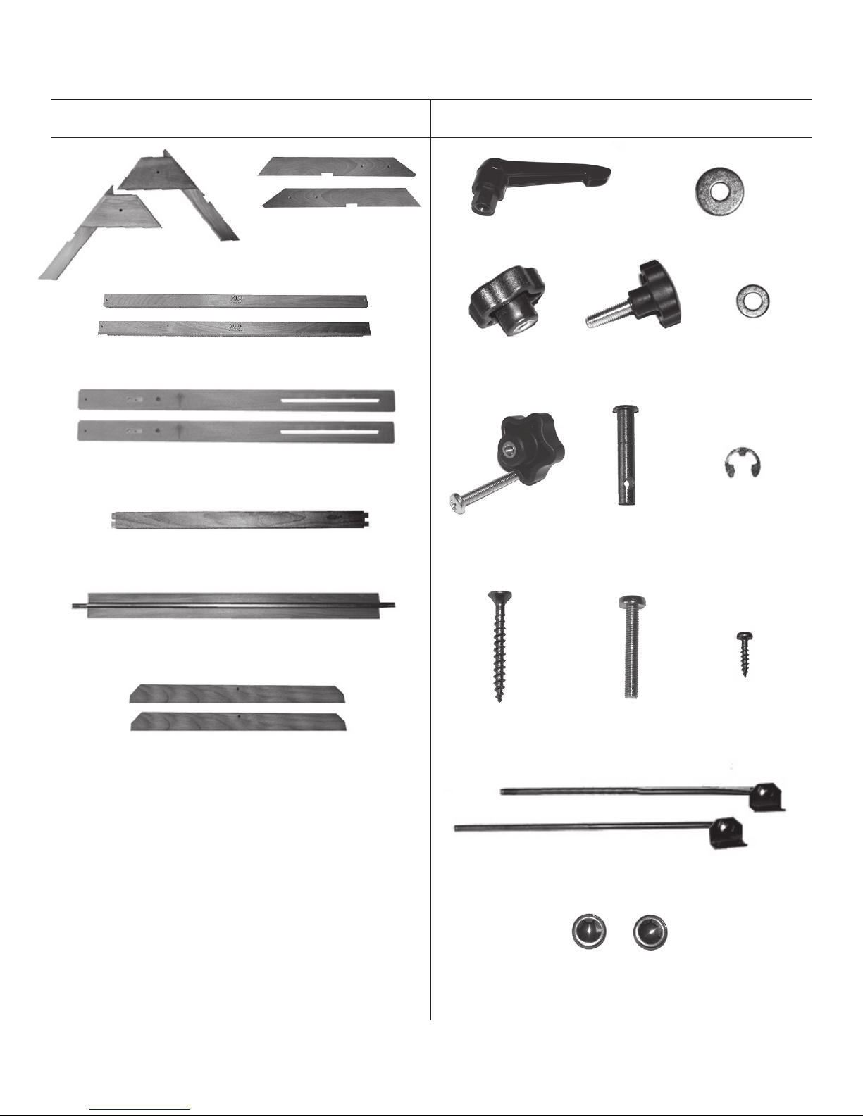
Contents of Carton: Contents of Parts Bag:
[2] A-Base Ends [A]
[2] A-Base Cross Supports [C]
[2] Chanelled Side Supports [D]
[1] Upper Cross ESupport [E]
[2] Left & Right Legs
for A-Base [B]
[1] Threaded Lever [AA] [1] Large Washer for Lever
[1] Female Knob
[CC]
[2] Female Knobs
with bolt & washer
included [FF]
[2] Male Knob [DD] [1] Washer for
[2] Large Pin with
hole [EE]
[BB]
Female Knob
[EE]
[2] “C” Washers for
Large Pins
[FF]
[1] Chanelled Cross Member with Threaded Rod [F]
[2] Drawing Top Braces [G]
[12] Long Wood
Screws [GG]
[2] Metal Tilt Adjustment Rods [JJ]
[2] Metal Pin End Caps for Tilt Rods [KK]
[2] 1-3/4” Bolts
[HH]
[4] Small Wood
Screws [II]
Created July 06 - RPI
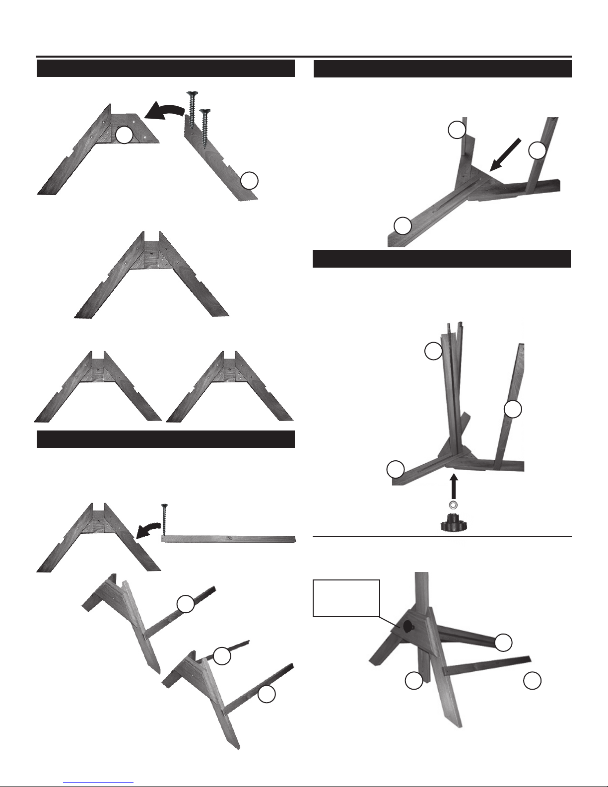
Assembly Instructions:
STEP 1] Assembling A-Base(s)
Take the A-Base end [A] as shown below and the Left Leg
[B] for the A-Base.
A
A-Base end [A]
Position the Left Leg [B] onto the A-Base, lining up holes.
Secure with [2] Long Wood Screws. Tighten. See below for
proper assembly.
Repeat with other side.
Now, you should have [2] complete A-Base Assemblies.
Long Wood
Screws [GG]
Left Leg [B]
B
STEP 3] Attaching Channelled Side
Take A-Base end that has the two supports attached and
place on flat surface. Position Channelled Side Support [D]
into middle section of A-Base. Making sure channel is on
bottom end. As shown below.
C
C
D
STEP 4] Adding Lower Support & Rod
With above assembly still laying flat on surface, insert one
end of Channeled Cross Member with Threaded Rod [F]
into Channelled Side Support [D] making sure rod end goes
through other end of A-base assembly. Secure with Washer
[EE] and Female Knob [CC]
F
STEP 2] Attaching A-Base Supports
Take one assembled A-Base end and attach [1] support
bar (with Logo reading up in correct position) and place into
notch and secure with [1] long wood screw [GG]. See below
for proper assembly.
A-Base Cross Supports [C]
A-Base Assembly
C
Proper assembly of
A-Base & support.
C
C
C
D
After securing with washer [EE] and Female Knob [CC],
turn assembly up onto base as shown below.
Washer [EE]
and Female
Knob [CC]
F
D
C
Repeat with other support.
Attach as shown to right.
Pg. 2
Created July 06 - RPI
 Loading...