

ELMTEC EC 25 Operation Instruction Manual
ELMTEC Ing. GmbH • Kattreppeln 28 • 38154 Königslutter • 05353 / 9545 - 0 •
www.elmtec.de •
|
info@elmtec.de
ELMTEC
Operation Instruction
Multifunction Calibrator
EC 25
ELMTEC Ing. GmbH • Kattreppeln 28 • 38154 Königslutter • 05353 / 9545 - 0 •
www.elmtec.de •
|
info@elmtec.de
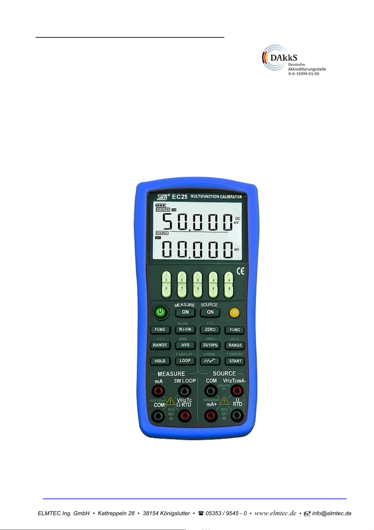
1 Introduction
This multifunction process calibrator (the calibrator in the following) is a handheld, battery-operated
instrument that measures and sources electrical and physical parameters. (See Table 1)
Table 1 Source and Measurement Function
Measurement
Sourcing
Function
Function
DCV
DCI CONT.
LOOP
OFF
LOOP
ON
OHM FREQ TC RTD SWITCH
DCV
DCI
RAMP ON
RAMP OFF
OHM
FREQ
PULSE
SWITCH
TC
RTD
Note:● indicating simultaneous use is allowed
× indicating simultaneous use is not allowed
● ● ● ● ● ● ● ● ●
× × × × × × × × ×
● ● ● ● ● ● ● ● ●
● ● ● ● ● ● ● ● ●
● ● ● ● × ● ● ● ●
● ● ● ● × ● ● ● ●
● ● ● ● × ● ● ● ●
● ● ● ● ● × × ● ●
● ● ● ● ● × × ● ●
Except the functions listed in Table 1, the calibrator has the following features as well:
You can operate the measurement and source function simultaneously. The LCD screen is divided
into two separate districts, whose upper part displays measurement information and lower part
displays source information.
TC measurement/source terminals and built-in lead connector of same temperature (RJ
compensation with auto-reference joint point)
Manual step source and auto -step and sweeping –step source
Room temperature monitoring under any operation
Measurement/source temperature monitoring function
Measurement/source mA% display
Measurement wave-filter function
Measurement manual-holding function
Pressure source auto-holding function
2 Standard Accessories
Make sure that the package contains all the accessories listed below. And if you find they are damaged
or any of them is missing, please contact the vendor from which you purchased the product as soon as
possible.
Two set of Industrial testing Lead
A set of Testing Lead
A set of Alligator clip
A Thermocouple Convertor
A quick reference guide
A User's Manual
One Fuse 50mA/250V
One Fuse 63mA/250V
ELMTEC Ing. GmbH • Kattreppeln 28 • 38154 Königslutter • 05353 / 9545 - 0 •
www.elmtec.de •
|
info@elmtec.de
3 Safety Information
For the correct and safe use of the instrument, be sure to follow the cautionary notes stated in this
manual whenever handling the instrument. The Company shall not be held liable for any damage
resulting from use of the instrument in a manner other than prescribed in the cautionary notes.
Warning identifies conditions and actions that pose hazards to the user; a Caution identifies
A
conditions and actions that may damage the meter or the equipment under test.
Refer to Table 2 for the explanation of the international electric symbols adopted by the calibrator or the
user’s manual.
Table 2 Explanations of International Electrical Symbols
EARTH GROUND
Warning
To avoid possible electric shock or personal injury:
Do not apply more than the rated voltage, as marked on the calibrator, between terminals or
between any terminal and earth ground;
Before use, verify the meter’s operation by measuring a known voltage;
Follow all equipment safety procedures;
Do not connect the probe of the testing lead with any live power when the other end has been
inserted into the current jack;
Do not use the meter if it is damaged. Before using the meter, inspect the case. Look for cracks or
missing plastic .Pay particular attention to the insulation surrounding the connectors;
Select the proper function and range for the measurement;
Make sure the battery door is closed and latched before operating the meter;
Remove test leads from the meter before opening the battery door;
Inspect the test leads for damaged insulation or exposed metal. Check test lead continuity. Replace
damaged test leads before using the meter;
When using the probes, keep fingers behind the finger guards on the probes;
Connect the common test lead before connecting the live test lead. When disconnecting test leads,
disconnect the live test lead first;
Do not use the meter if it operates abnormally. Protection may be impaired. When in doubt, have
the meter inspect;
Do not operate this instrument in areas where inflammable or explosive gases or vapor exists. It is
extremely hazardous to use the instrument under such environments;
Do not operate the meter around explosive gas, vapor, or dust;
When use the pressure module, do make sure the process pressure line is shut off and
depressurized before connecting or disconnecting the pressure module;
Use only type 4 AAA batteries, properly installed in the meter case, to power the meter;
Do disconnect the testing lead before shifting to different source or measurement functions;
When servicing the meter, use only specified replacement parts.
To avoid false reading, which could lead to possible electric shock or personal injury, replace the
batteries as soon as the low battery indicator (
Caution
To avoid possible damage to meter or to equipment under test:
Disconnect the power and discharge all high-voltage capacitors before testing resistance or
continuity.
Use the proper jacks, functions, and ranges for the measurement or source operation.
WARNING
INFORMATION
) appears.
ELMTEC Ing. GmbH • Kattreppeln 28 • 38154 Königslutter • 05353 / 9545 - 0 •
www.elmtec.de •
|
info@elmtec.de
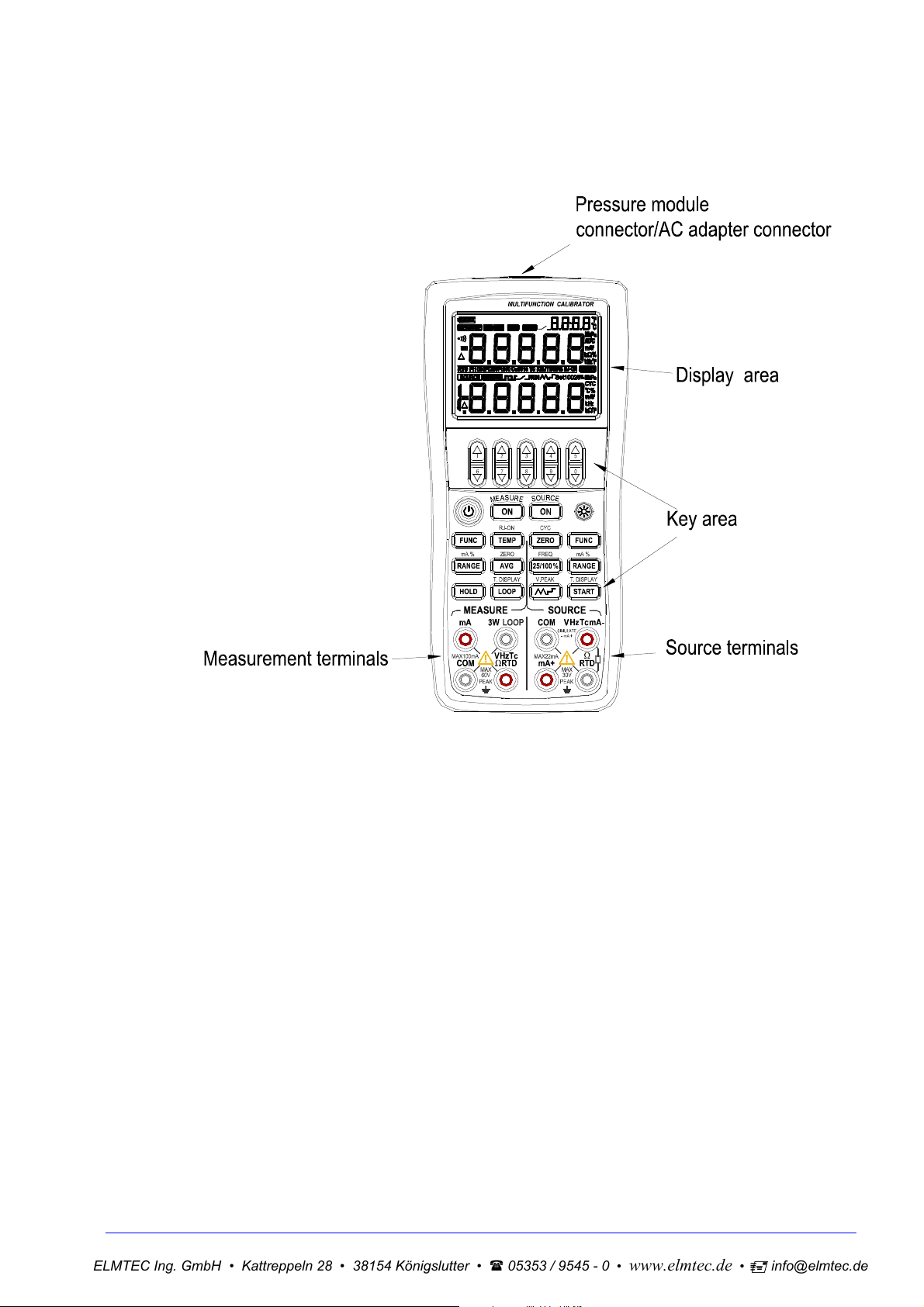
4 Familiar With the Calibrator
Figure1 Entire Graphic
ELMTEC Ing. GmbH • Kattreppeln 28 • 38154 Königslutter • 05353 / 9545 - 0 •
www.elmtec.de •
|
info@elmtec.de
4.1 Measurement/ Source Terminals
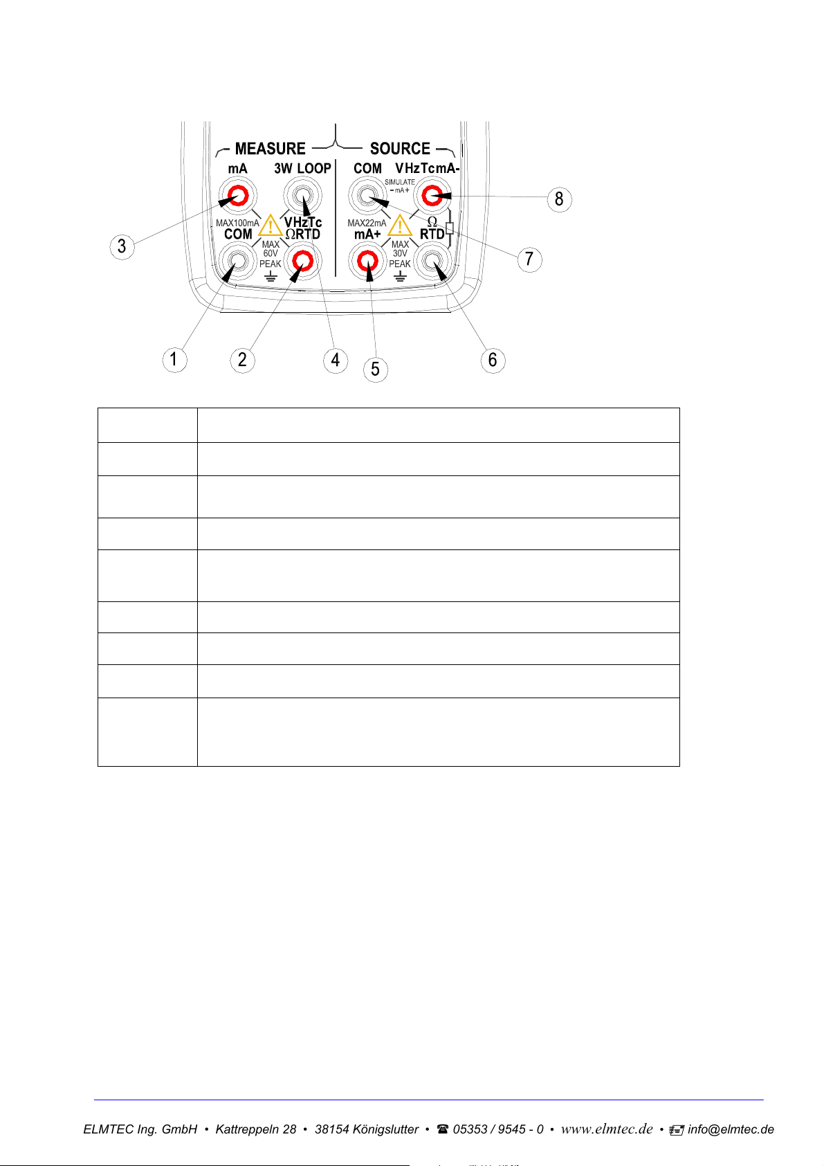
Figure 2 shows the measurement /source terminals of the calibrator. Table 3 explains their use.
Figure 2 Measurement/ Source Terminals
Table 3 Measurement/ Source Terminals
Terminal Function
① All the common (return ) (-)terminals of measurement function
Measurement
②
Signals(+):DCV、OHM、FREQ、TC、RTD、SWITCH、CONT
③ Measurement Signals(+):DCmA
3W Terminal:measurement terminal of the 3W OHM
、RTD
④
LOOP Terminal:+24VDC Loop Power Terminal
⑤ Source Signals:(+)DCmA
⑥ Source Signals:(-)OHM、RTD
⑦ All the common (return ) (-)terminals of source function
Source
⑧
Signal:(+)DCV、OHM、TC、RTD、XMT、FREQ、CYC、SWITCH
Source Signal:(-)DCmA
ELMTEC Ing. GmbH • Kattreppeln 28 • 38154 Königslutter • 05353 / 9545 - 0 •
www.elmtec.de •
|
info@elmtec.de
4.2 Keys
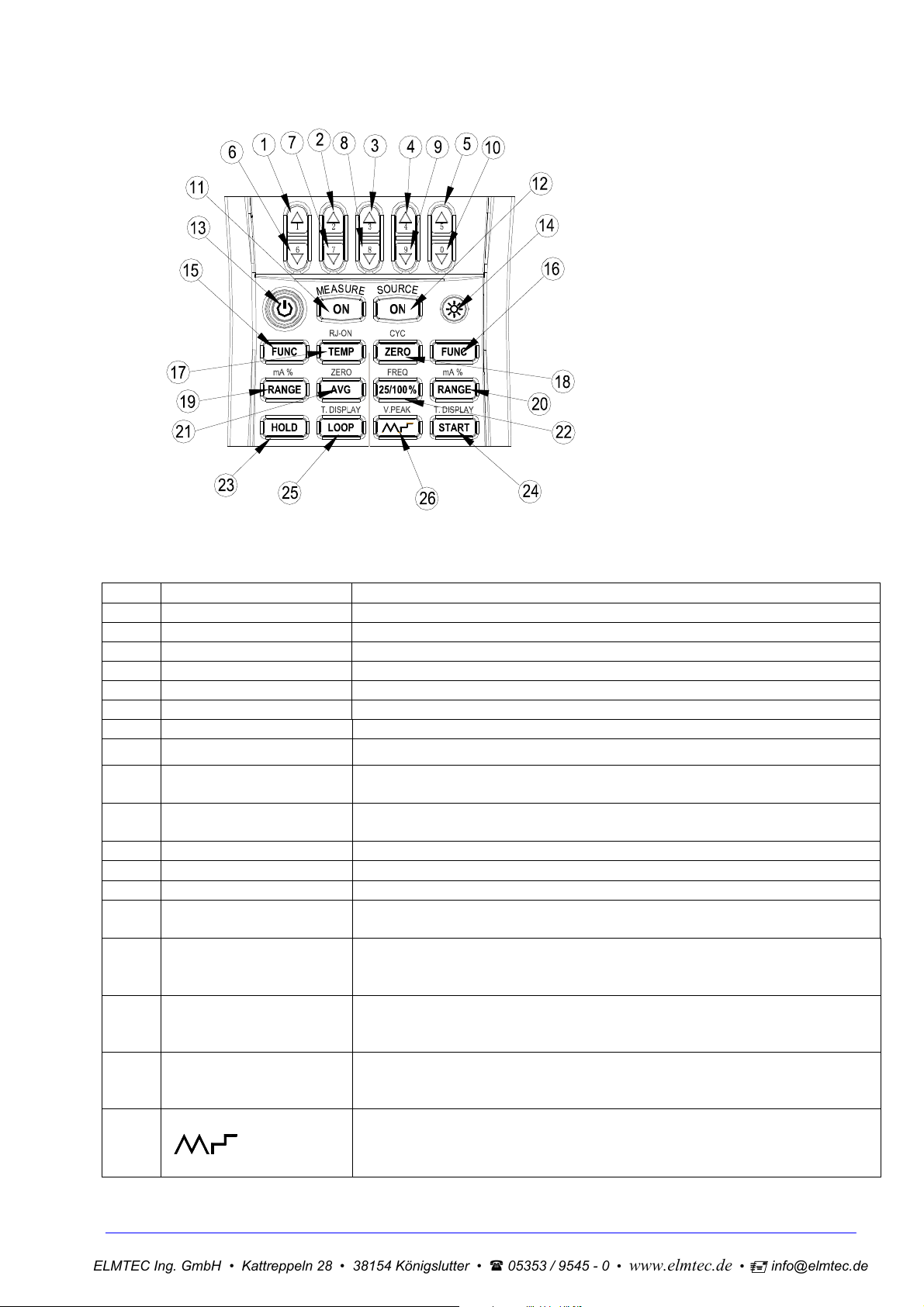
Figure 3 shows keys of the calibrator. Table 4 explains their use.
Figure 3 keys
Table 4 Functions of the keys
No. Name Function
1~5 Source value set Increment of source set point
6~10 Source value set Decrement of source set point
11 Measurement ON Turn on or off measurement function
12 Source ON Turn on or off source function
13 Power Turn on or off the power
14 Backlight Turn on or off the backlight
15 Measurement FUNC Select measurement function
16 Source FUNC Select source function
17 TEMP Turn on or off room temperature monitoring function. In TC source or
measurement function, turn on or off the RJ compensation function.
18 ZERO Set the source value to zero-point.
In pulse source function, set the pulse number.
19 Measurement RANGE Select measurement range Measurement mA and percentage shifting.
20 Source RANGE Select source range Source mA and percentage shifting.
21 AVG Measuring average valueRelative measured value of pressure
22 25/100% In mA source function, select 25% or 100% manual step output mode.
In pulse number, frequency or switch source, set the frequency value.
23 HOLD Measured value holding
Source pressure and measure contact simultaneously, releasing the
locked pressure reading.
24 START Source auto-pulse number, turn on mA auto-stepping or sweeping
function. Convert the sourced TC temperature and the mV, the
sourced RTD temperature and the Ohm.
25 LOOP 24v Loop circuit power
Convert the measured TC temperature and the mV, the measured
RTD temperature and the Ohm.
26
In DCmA source function ,select the auto-wave mode.
In frequency or pulse source, set the source amplitude.

ELMTEC Ing. GmbH • Kattreppeln 28 • 38154 Königslutter • 05353 / 9545 - 0 •
www.elmtec.de •
|
info@elmtec.de
4.3 Display Screen
Figure 4 shows a typical display screen.
Figure 4 typical LCD display
a:Battery level indicator
b:Measurement
c:Measurement function on
d:Measurement function off
e:Average value for measurement
f: Display –hold for measured value
g:Switch measurement
h:Unit of room temperature
i:Beeper of measurement continuity
j:Measured value
k:Unit of measured value
l:Divide line of measurement and source mode displays
m:Types of RTD measurement / source
n:Divide line of measurement and source mode displays
o:Types of TC measurement / source
p:Reference Junction Compensation On
q:24V Loop Power Supply on
r:Source
s:Source function on
t:Source function off
u:Set -point for source
v:Set information for source
w:Unit of set -point for source
x:Measurement pressure reading zero off
y:Source pressure reading zero off

ELMTEC Ing. GmbH • Kattreppeln 28 • 38154 Königslutter • 05353 / 9545 - 0 •
www.elmtec.de •
|
info@elmtec.de
5 Before starting source/measurement
Operating Precautions
Precautions for Safe Use of the Instrument
When using the instrument for the first time, be sure to read the instructions given in Section Four
“Precautions for Safe Use of the Instrument.”
Do not open the instrument’s case.
Contact the vendor from which you purchased the instrument, for a service of inspecting or
adjusting the internal assembly.
In case of failure
Should the instrument begin to emit smoke, give off an unusual odor, or show any other anomaly,
immediately turn off the POWER key. If you are using an Charger, disconnect the plug from the
wall outlet. Also cut off power to the object under test that is connected to the input terminals.
Then, contact the vendor from which you purchased the instrument.
Charger
Use an Charger dedicated to the instrument. Avoid placing any load on the Charger, or prevent any
heat-emitting object from coming into contact with the adapter.
General Handling Precautions
Before carrying around the instrument turn off power to the object under test, and then the POWER
key of the instrument. If you are using an Charger, disconnect the power cord from the wall outlet.
Finally, detach all lead cables from the instrument. Use a dedicated carry case when transporting
the instrument.
Do not bring any electrified object close to the input terminals, since the internal circuit may be
destroyed.
Do not apply any volatile chemical to the instrument’s case or operation panel. Do not leave the
instrument in contact with any product made of rubber or vinyl for a prolonged period. Be careful
not to let a soldering iron or any other heat-emitting object come into contact with the operation
panel, as the panel is made of thermoplastic resin.
Before cleaning the instrument’s case or operation panel disconnect the power cord plug from the
wall outlet if you are using an Charger. Use a soft, clean cloth soaked in water and tightly
squeezed to gently wipe the outer surfaces of the instrument. Ingress of water into the instrument
can result in malfunction.
If you are using an Charger with the instrument and will not use the instrument for a prolonged
period, disconnect the power cord plug from the wall outlet.
For handling precautions regarding the batteries, see “Installing or Replacing the Batteries”.
Never use the instrument with the cover of the battery holder opened.
Environmental Requirements
Use the instrument in locations that meet the following environmental requirements:
Ambient temperature and humidity
Ambient temperature range: 0 to 50℃
Ambient humidity range:
Flat and level locations
Do not use the instrument in locations that are
Exposed to direct sunlight or close to any heat source.
Exposed to frequent mechanical vibration.
Close to any noise source, such as high-voltage equipment or motive power sources.
Close to any source of intensive electric or electromagnetic fields.
Exposed to large amounts of greasy fumes, hot steam, dust or corrosive gases.
Exposed to unstable or a risk of explosion due to the presence of flammable gases.
30 to 80% RH. Use the instrument under non-condensing condition.
ELMTEC Ing. GmbH • Kattreppeln 28 • 38154 Königslutter • 05353 / 9545 - 0 •
www.elmtec.de •
|
info@elmtec.de
Note:
Use the instrument under the following environmental conditions if precise source or measurement
is your requirement:
Ambient temperature range: 23±5°C;
Ambient humidity range: 20 to 80% RH(non-condensing)
When using the instrument within a temperature range of 0 to 18°C or 28 to 50°C, add a value
based on the temperature coefficient shown in Chapter 18“Specifications” to the given accuracy
rating.
When using the instrument at an ambient humidity of 30% or lower, prevent electrostatic charges
from being produced, by using an antistatic mat or any other alternative means.
Condensation may occur if you relocate the instrument from places with low temperature and
humidity to places with high temperature and humidity, or if the instrument experiences any sudden
temperature change. In that case, leave the instrument under the given ambient temperature for at
least one hour to ensure that the instrument is free from condensation, before using the instrument.
Installing or Replacing the Batteries
Warning
To avoid electrical shock, always remove the source or measurement lead cables from the object under
test, as well as from the instrument itself.
Caution
To avoid the risk of fluid leakage or battery explosion, install batteries with their positive and
negative electrodes correctly positioned.
Do not short-circuit the batteries.
Do not disassemble or heat the batteries or throw them into fire.
When replacing batteries, replace all of the four batteries at the same time with new ones from the
same manufacturer.
If the instrument will not be used for a prolonged period, remove the batteries from the instrument.
Step 1: Remove the lead cables and
charger and turn off the calibrator before you begin installing
batteries.
Step 2: Remove the battery holder cover by sliding it in one-quarter counterclockwise direction and turn
off the calibrator.
Step 3: Install four alkaline batteries of same type in the battery holder with their positive and negative
electrodes positioned correctly as indicated on the holder.
Step 4: After replacement, reattach the battery holder cover.
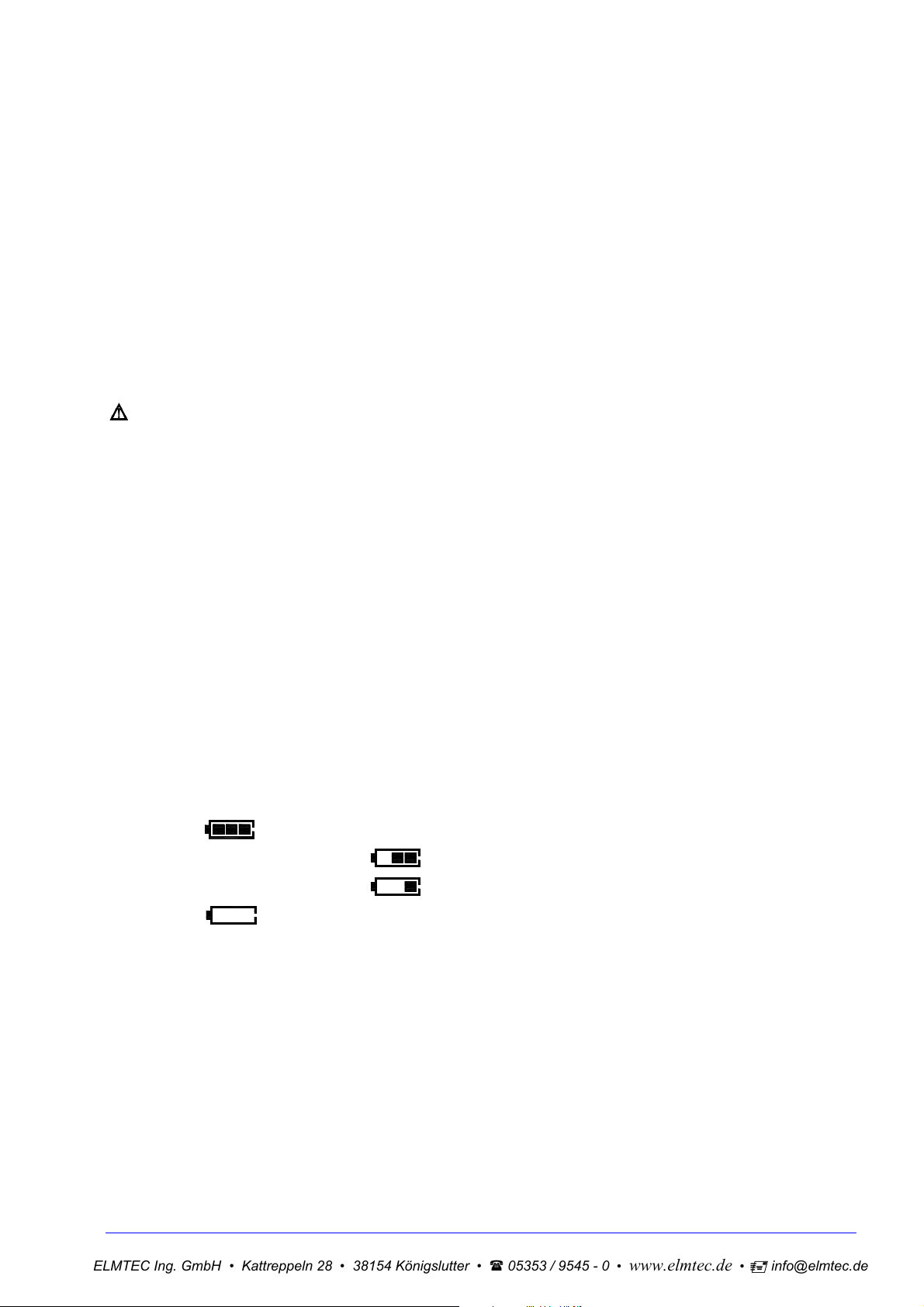
Indication of Battery Level
The battery replacement indicator shows the battery level in five steps according to the measured
voltage of the batteries.
Full battery:
The battery level is below 50% full:
The battery level is below 25% full:
Low battery:
The dictation flashes in sequence when getting charged.
Note that the battery replacement indicator is driven by directly measuring the battery voltage when the
calibrator is in actual operation. Consequently, the indicator may read differently depending on the
battery load condition (e.g., the load condition of the source output or on/ off state of the measurement
function) if the batteries are too low. If the calibrator will be used under a wide variety of conditions, it is
advisable that the battery replacement indicator be verified under heavy loads (MEASURE mode is on
and the SOURCE mode is set to the 20 mA/10 V output).

ELMTEC Ing. GmbH • Kattreppeln 28 • 38154 Königslutter • 05353 / 9545 - 0 •
www.elmtec.de •
|
info@elmtec.de
Connecting the Charger
Warning
Make sure the voltage of the AC power source matches the rated supply voltage of the
before connecting the
Do not use any
Charger other than the dedicated Charger from the Company.
Charger to the AC power source.
Charger,
Do not charge non Ni-Cd, Ni-MH batteries or wasted batteries.
Step 1: Make sure the calibrator is turned off.
Step 2: Insert the plug of the optional
Charger into the Charger connection jack.
Note
Turn off the calibrator before connecting or disconnecting the Charger from AC power, plugging
in/out the
Plug out the
Charger connection jack.
Charger from the Charger connection jack of the calibrator when discharging.
Do not charge the calibrator without any battery in.
Turning On the Power
Pressing the Power key once when the power is off turns on the calibrator.
Pressing the Power key for 2 seconds turns off the calibrator.
Turning On/Off MEASURE Mode
The measurement function is in off state after turning on the calibrator.
If the MEASURE function is not needed and therefore turned off, power to the measurement circuit
is also turned off within the calibrator. Thus, you can save on battery power if the calibrator is
running on batteries.
Turning off the MEASURE function causes the on-screen measured value to disappear, and the
“OFF” indicator appears on the display simultaneous.
To resume measurement when the MEASURE function is off, press the key once again.
Automatic Power-off
When the calibrator is running on batteries and no key is operated for approximately ten minutes, the
calibrator turns off automatically. The automatic power-off time could be reset in the factory default
parts, see Chapter 10 “Factory Default”.
Turning On/Off the Backlight
The LCD can be backlit. Pressing the key turns on the backlight, while pressing the key once again
turns it off. This feature makes it easier for you to view the LCD when operating the calibrator in dark
places or when carrying out source or measurement. Battery life shortens when the calibrator is
operated on batteries.
Note
The backlight automatically turns off after 30 seconds. Press the key once more to relight it.
The time could be reset in the factory default parts, see Chapter 10 “Factory Default”.
 Loading...