

ElmoTech 1TRACK Installation And Operation Manual
Installation and Operation Guide

Information in this documentation is subject to change without
notice and does not represent a commitment on part of
Elmo-Tech Ltd. The software described in this document is
subject to the license agreement that is included with the
product, which specifies the permitted and prohibited uses of
the product. Any unauthorized duplication or use of this
documentation, in whole or in part, in print, or in any other
storage or retrieval system is prohibited.
No part of this publication may be reproduced, transmitted,
transcribed, stored in a retrieval system, or translated into any
language in any form by any means for any purpose other than
the purchaser’s personal use without the permission of
Elmo-Tech Ltd.
© 2002-09 Elmo-Tech Ltd. All rights reserved.
Unless otherwise noted, all names of companies, products,
street addresses, and persons contained herein are part of a
completely fictitious scenario and are designed solely to
document the use of an Elmo-Tech product.
Contact Us
Corporate Headquarters
Elmo-Tech Ltd.
2 Ha-Barzel St.,
P.O. Box 13236,
61132 Tel Aviv, Israel
Tel: 972-3-7671800
Fax: 972-3-7671801
U.S.A Customers, call 1-800-313-1483
E-mail: contact@elmotech.com
Visit us at: www.elmotech.com

i
Table of Contents
1 Introduction.................................................................... 1
Components..................................................................... 2
LED Indicators.................................................................. 2
2 Installing the 1TRACK Unit ............................................. 5
Installation Equipment....................................................... 5
Installation Tools .............................................................. 6
Verifying Offender Information in the E3-MWS ...................... 6
Activating the 1TRACK Unit ................................................ 6
3 Status Alerts ................................................................. 11
Low Battery ....................................................................11
Motion No GPS ................................................................12
Strap Tamper .................................................................. 12
Device Tamper ................................................................ 12
Geographic Zone Alerts.....................................................13
4 Dismantling the 1TRACK Unit........................................ 15
Before Dismantling...........................................................15
Performing an End of Service............................................. 15
Removing the 1TRACK Unit ...............................................16
5 Cleaning the 1TRACK Unit ............................................. 19

1TRACK Installation and Operation Guide
ii
List of Figures
Figure 1 1TRACK Components ................................................2
Figure 2 1TRACK LED Indicators .............................................3

1
1 Introduction
The 1TRACK wearable tracking unit was designed specifically for
Offender monitoring operations. With security redundancies and
anti-tamper mechanisms built-in across the platform, the
1TRACK unit provides a trustworthy and reliable tracking
system.
The 1TRACK unit operates on the E3 software platform and
benefits from over a decade of field experience.
The 1TRACK unit tracks Offenders outdoors utilizing GPS
technology and communicates the data to the monitoring center
via GPRS.
Each monitored Offender is assigned a tracking unit which
continuously tracks the Offender’s location in real-time. The
1TRACK unit stores and processes the tracking data and
communicates with the monitoring center or assigned Officers to
report locations or violations. Alerts are preset to the Offender’s
individual schedule and zone restrictions.
1TRACK Installation and Operation Guide
2
Components
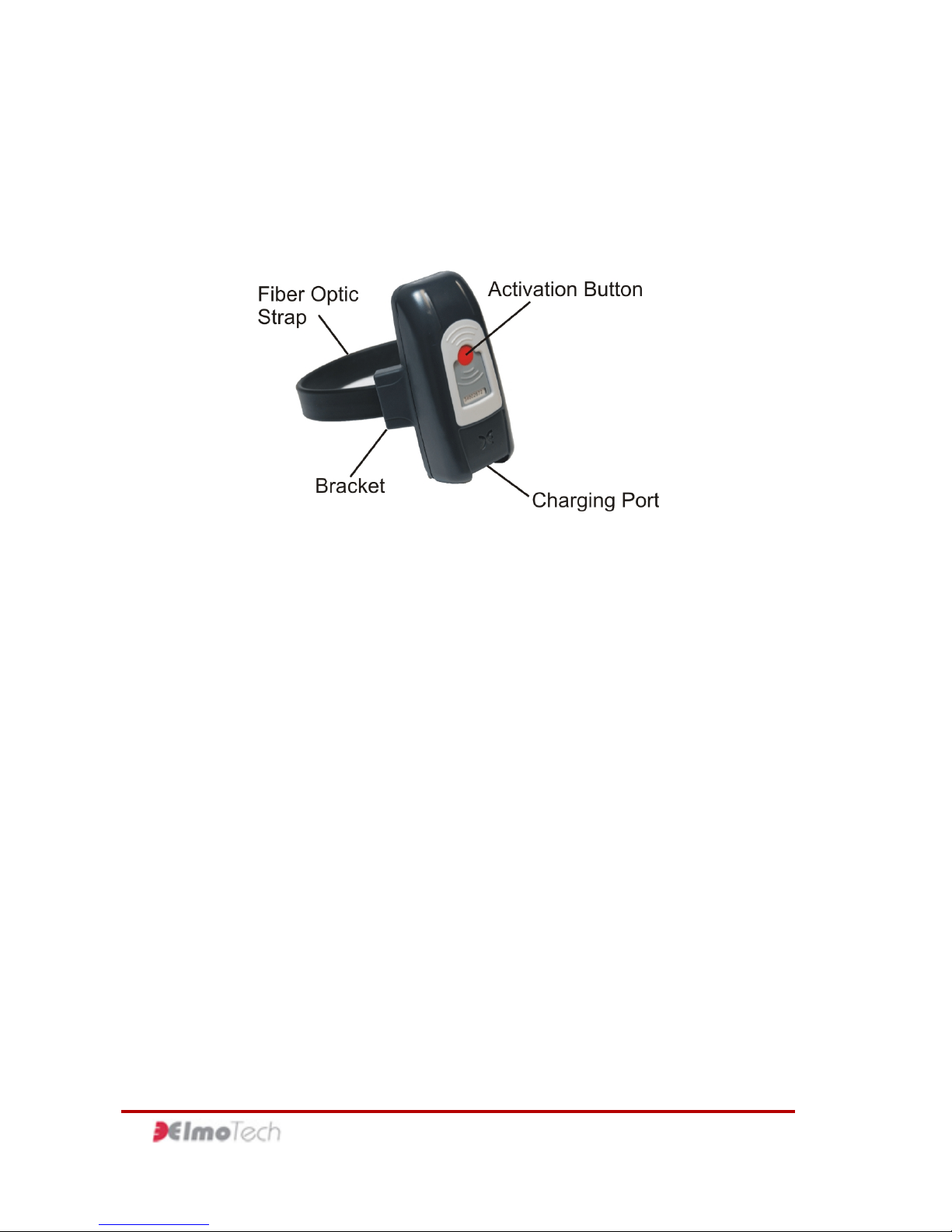
The 1TRACK unit features the following components:
Figure 1 1TRACK Components
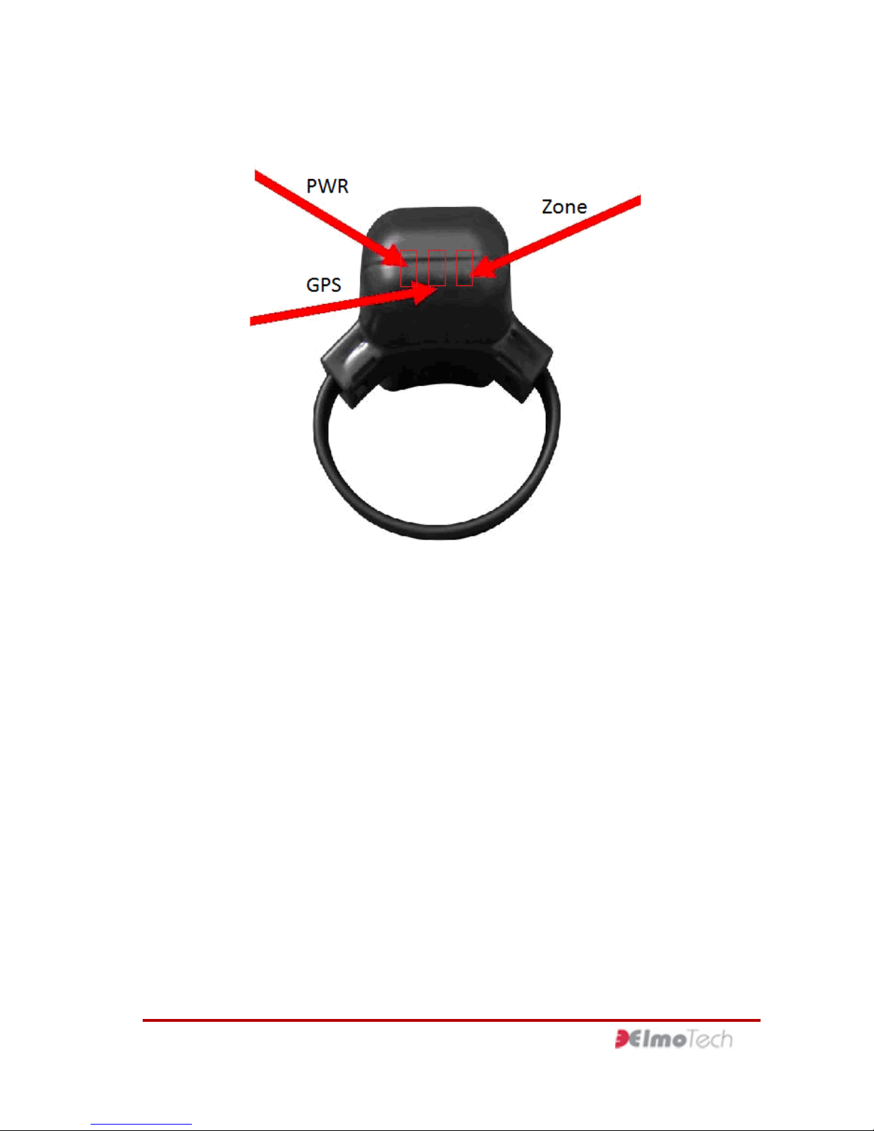
LED Indicators
The 1TRACK unit features three LED indicators on its top. Each
LED can flash green or red to inform the Offender of the unit’s
status. If vibration notification is enabled, the 1TRACK unit also
prompts the Offender to look at the LEDs by vibrating. The LEDs
are labeled as follows:
f PWR – see page 3
f GPS – see page 4
f Zone – see page 4
1 Introduction
3
Figure 2 1TRACK LED Indicators
PWR
The PWR LED indicates the condition of the 1TRACK unit
battery.
f Flashing Green – The 1TRACK unit is activated or is in the
process of being activated, and the battery does not need to
be charged.
f Flashing Red – The 1TRACK unit is activated and the
battery needs to be charged.
f Solid Green – The 1TRACK unit is connected to the charger
and the battery has been completely recharged. You may
remove the 1TRACK unit from the charger.
 Loading...