

ElMod Fusion ECO, Fusion PRO, Fusion PRO Rev.F Detailed Installation Instructions And User Manual
ElMod Fusion ECO & Fusion PRO Rev.F
Detailed installation instructions and user manual
Before installation always read carefully all these instructions.
We congratulate on your purchase of the ElMod Fusion, the innovative and universal full-option-solution for different types of vehicles.
The ElMod Fusion enhances your model by true to scale movement, extensive weapon-, lighting- and other functions combined with
simple installation. All functions right down to the last detail may be easily adjusted on your Windows® or Apple® Computer or an
Android® Smartphone or Tablet by over 100 parameters which are logically grouped and explained in detail. By ongoing
improvements and software updates, which may be easily applied at home within few minutes, you bought a future-proof product.
Scope of delivery
Before starting the installation, check the scope of delivery for completeness.
• ElMod Fusion PCB
• volume control rotary knob with cable
• cable for the RC receiver
• plug with for connecting to the battery
• plug for connecting up to two drive motors
• cable for connecting to the loudspeaker
• microSD card (already plugged-in on the PCB)
• USB dongle and an USB cable for connecting to the computer
• ElMod Fusion PRO only: housings and cables for assembly of up to 5 external light sources
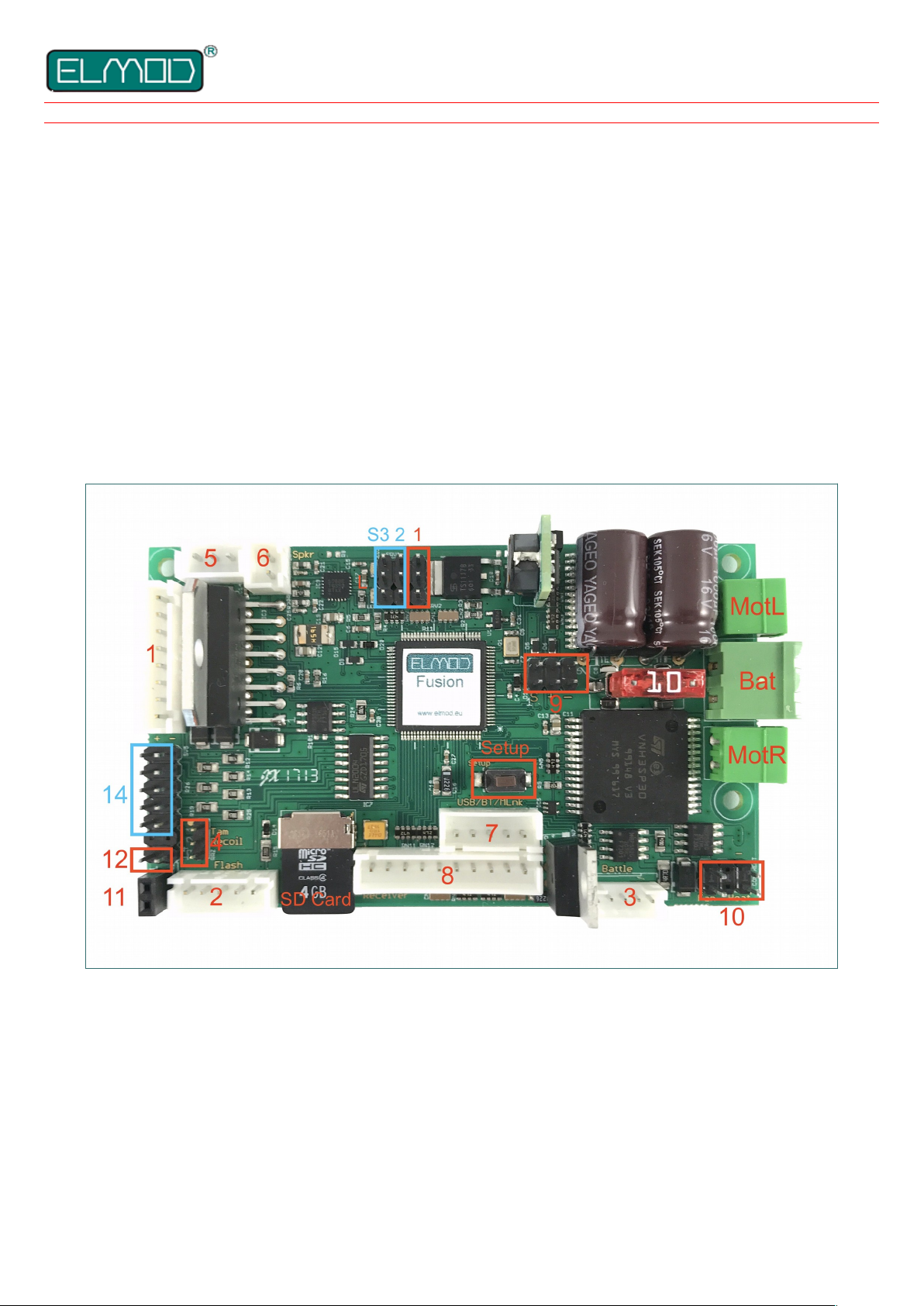
Fusion ECO and Fusion PRO
Bat battery connector
MotR connector for the right motor
MotL connector for the left motor
Sw pushbutton for the setup, firmware update and reset
S1 servo connectors
L status LEDs
SD microSD card
1 turret connector (HengLong®)
2 muzzle flash connector (Taigen®, HengLong®)
3 connector for IR battle functions
4 connector for the Tamiya® barrel recoil mechanics
5 connector for the volume control rotary knob
6 connector for the loudspeaker
7 connector for the USB dongle and ElMod BT adapter
8 connector for the RC receiver
9 connectors for external motor drivers
10 connector for a smoke unit
11 connector for Taigen®, HengLong
®
recoil/shot mechanics
12 connector for Taigen®, HengLong
®
recoil servo pcb
additively Fusion PRO (marked blue)
14 connector for additional lights
S2,S3 servo 2 & 3
Hint: all connectors are marked and described on the bottom side of the PCB.
- 1 - © ElMod - 19-09-02
In this paragraph the installation is described step by step. It is essential that each step is accomplished correctly and completely.
Wrong or improper connection may cause malfunction or damage and/or destruction of the electronics, the installed components or
the model. Please contact the support of your dealer if you have further questions regarding the installation.
Connection of the power supply
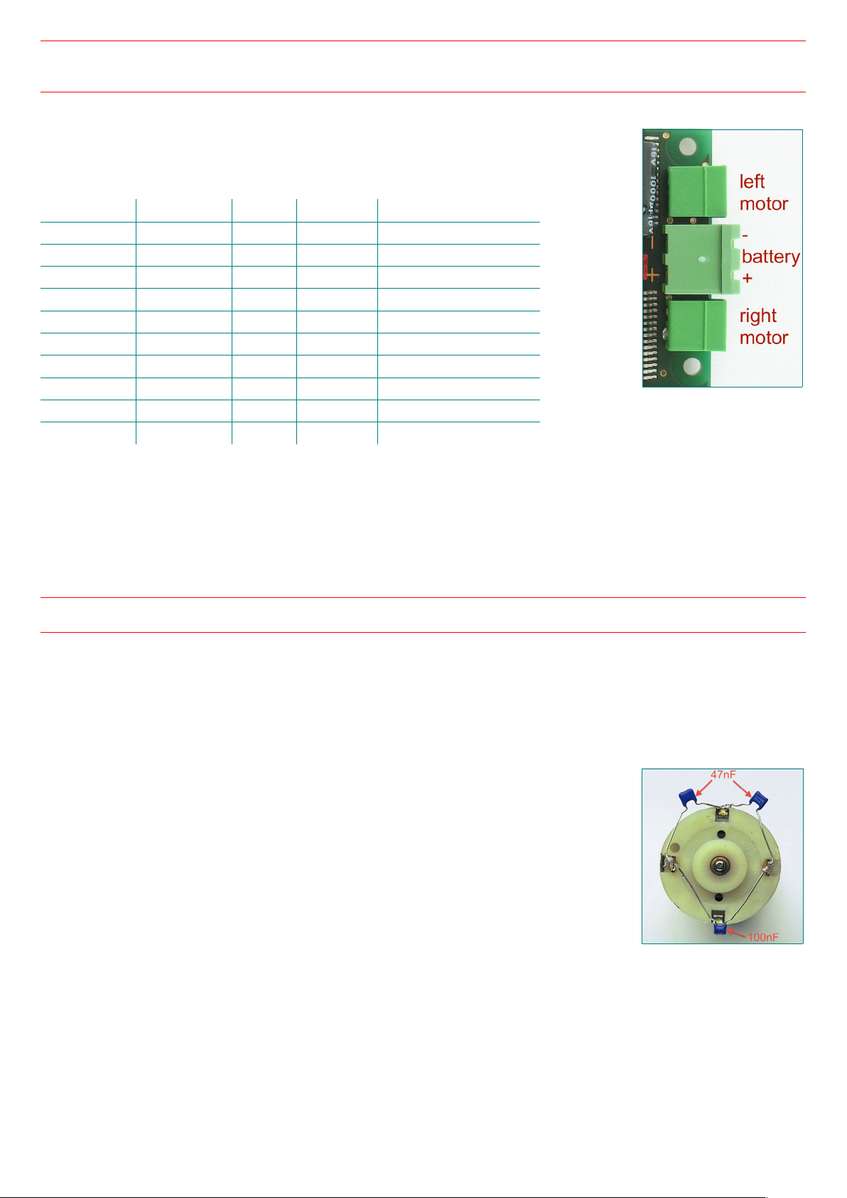
• connect the red cable with the + terminal and the black cable with the – terminal of the battery plug.
Incorrect connection causes the destruction of the electronics!
• keep the cable length as short as possible in order to prevent interferences
The following battery types are supported:
Variant Battery type Cells Voltage under voltage shut down
ECO/PRO NiMh/NiCd 6 7,2 V 6 V
ECO/PRO NiMh/NiCd 7 8,4 V 7 V
ECO/PRO NiMh/NiCd 8 9,6 V 8 V
PRO NiMh/NiCd 9 10,8 V 9 V
PRO NiMh/NiCd 10 12 V 10 V
ECO/PRO LiPo 2S 7,4 V 6,4 V
PRO LiPo 3S 11,1 V 9,6 V
PRO Pb - 12V 10V
ECO/PRO LiIon 2S 7,4 V 6 V
PRO LiIon 3S 11,1 V 9 V
If the battery voltage drops below a certain threshold, the protective under voltage shut down will be activated. The voltage value
depends on the used battery type as listed in the table.
If the battery voltage exceeds a maximum value, the protective over voltage shut down will be activated.
The protective shut down (under voltage and over voltage) deactivates all functions of the ElMod Fusion. The engine turns off and the
vehicle cannot be operated any more. The announcement "Low Battery" or "Voltage too high" follows via loudspeaker every 5
seconds and the red status LED shows an error state (see chapter "Status LEDs").
The factory setting is NiMh/NiCd-battery 7,2V (6 cells). If another battery type is used, it has to be set in the configuration software,
otherwise the under voltage protection shut down won't work correctly.
If any other battery type as listed is used, a proper function cannot be guaranteed.
The warranty is void if higher voltage than allowed is used!
Connection of the drive motors (integrated drivers)
The ElMod Fusion supports one or two DC motors for the main drive. Brushless motors and motors with an extra high current
consumption may be used optionally by commercially available external drivers (see next chapter). It is not possible to operate
integrated and external drivers simultaneously.
The maximum current consumption of the drive motors is internally limited to 30 A peak. The allowed permanent load is 10 A. The
motor drivers need no further cooling. They are protected against short circuit and overload.
• attach the motor wires for the right drive to the connector MotR
• attach the motor wires for the left drive to the connector MotL
• for vehicles with only one drive motor use one of the two connections
• it makes no difference which cable (+/- of the motor) is connected to which screw of the
corresponding terminal
• keep the cable length as short as possible in order to prevent interferences! For additional
interference protection the motor cables can be twisted.
• IMPORTANT! The motors must be interference-suppressed. This is accomplished with the use of
three capacitors as shown in the figure. Many motors are interference-suppressed already. Please
check this by asking the producer or distributor of your motors.
For checking the correct wiring of the motors proceed as follows:
• make sure that the driving shaft is free to rotate and the model cannot move uncontrollably
• connect a fully charged battery to the electronics and connect the power supply in accordance with section "connection of the
power supply"
• please wait for 3-4 sec. until the blue LED starts blinking constantly
• press and hold the setup pushbutton
• the motors start rotating after around 3 seconds. The motors are connected correctly if the left one is rotating slightly slower than
the right one
• every few seconds the motors change their rotation. Release the button when the chains or wheels rotate forward. Now the motors
- 2 - © ElMod - 19-09-02

are set up correctly.
• when only one motor is attached proceed accordingly. Release the button when the motor rotates forward.
Connection of the drive motors (external drivers)
Commercially available external drivers may be connected directly to the ElMod Fusion. The operating type (internal/external drivers)
must be set by the ElMod App (tab "drive", parameter "motor drivers"). It is not possible to operate integrated and external drivers
simultaneously. The external drivers are connected with the connectors 9. The black ground wire of the
drivers points to the right edge of the PCB (towards the battery connector).
Smoke generator
The smoke generator is connected to the connector for the smoke generator (connector 10).
• if the smoker generator provides two wire operation only (combined fan and heater), attach it to the fan
labeled connector
• if the smoker generator provides four wire operation (separated fan and heater wires), attach the fan
wires and the heater wires to the respective connector
• the polarity of the connectors are printed on the board
Turret functions
The ElMod Fusion provides a HengLong® compatible 8-pin turret terminal (connector 1). It is used by the
turret rotation motor, gun elevation motor, main gun trigger motor, front lighting and muzzle flash of the
main MG.
• an optional adapter allows the use of a Tamiya® turret. The functions turret rotation, main gun elevation and also main lighting and
muzzle flash of the main MG are supported
• an optional cable offers the connection of a turret with a different wiring to the ElMod Fusion board.
The voltage on all turret components is always equal to the voltage of the battery. If you plan to use motors with lower voltage, reduce
the setting for maximum speed in the ElMod App of the corresponding motor. For example the maximum speed of a 7.2 V motor in a
12 V tank should not excess 60% (60% of 12V = 7,2V).
Also keep in mind that the maximum current per motor must not exceed 2 A. Higher current may destroy the electronics.
Shot function
In principle, all HengLong®/Taigen® shot systems are operable as soon as the 8-wire turret cable is
attached to connector 1. In this case the shot function is active as long as the trigger is actuated.
Depending on the assignment of the plugs and the settings in the ElMod App, this basic function can be
extended. The corresponding parameter "Recoil Type" in the ElMod App can be found in the "Weapons"
tab.
• Setting Standard corresponds to the basic setting (turret cable only). If the ground cable of the shot
system is also connected to the negative pole of the battery, the firing mechanism automatically
returns to its initial position after the trigger is released.
• Setting Airsoft is suitable for the firing mechanism for plastic balls. The shot sound sounds at the same
time as the ball is fired. For this purpose, one more cable must be connected in addition to the 8-wire
turret cable and the ground wire. The white-orange cable from the switch for the position of the
shooting mechanism has to be attached to connector 12. The orange wire points to the edge of the
board (mark "O" at the bottom of the board).
• Setting Airsoft with recoil is suitable for tanks with a firing mechanism for plastic balls AND
simultaneous recoil mechanics via a turret built-in control electronics with a servo. The wiring is the same as for the airsoft shot
function. Additionally electronics for the recoil mechanics has to be attached to connector 11. Plus and minus are marked on the
board and correspond to the red or black wire of the cable.
• Setting Tamiya Recoil is intended for the Tamiya® recoil mechanics. For this the connector of the mechanics has to be attached to
connector 4. The white cable faces the marking (golden dot) on the upper side of the board.
If your cabling differs from the one described here or if you are unsure, please contact your dealer's support! Errors in the wiring can
damage or destroy the electronics of the tank or the ElMod circuit board!
A further possibility to simulate the barrel recoil is the use of a dedicated servo with the appropriate mechanics. Details are described
in this section Servos. The servo recoil is independent of the setting "Recoil Type" in the ElMod App.
Muzzle flash
The HengLong®/Taigen® Xenon flash or the HengLong® muzzle flash LED are equipped with a 5-pin plug and has to be connected to
connector 2. The Tamiya® Xenon flash is not supported. If an LED is used, the flash may be weak depending on the type of LED. The
ElMod LED Flash Booster provides a bright LED flash in this case.
- 3 - © ElMod - 19-09-02
Light functions
The ElMod Fusion is able to control several light channels:
• front light (white LEDs) and MG muzzle flash (ultra bright white LED) on the HengLong® turret
connector (turret and weapon functions)
• xenon or LED muzzle flash of the main gun and muzzle flash of the MG (see chapter turret and
weapon functions)
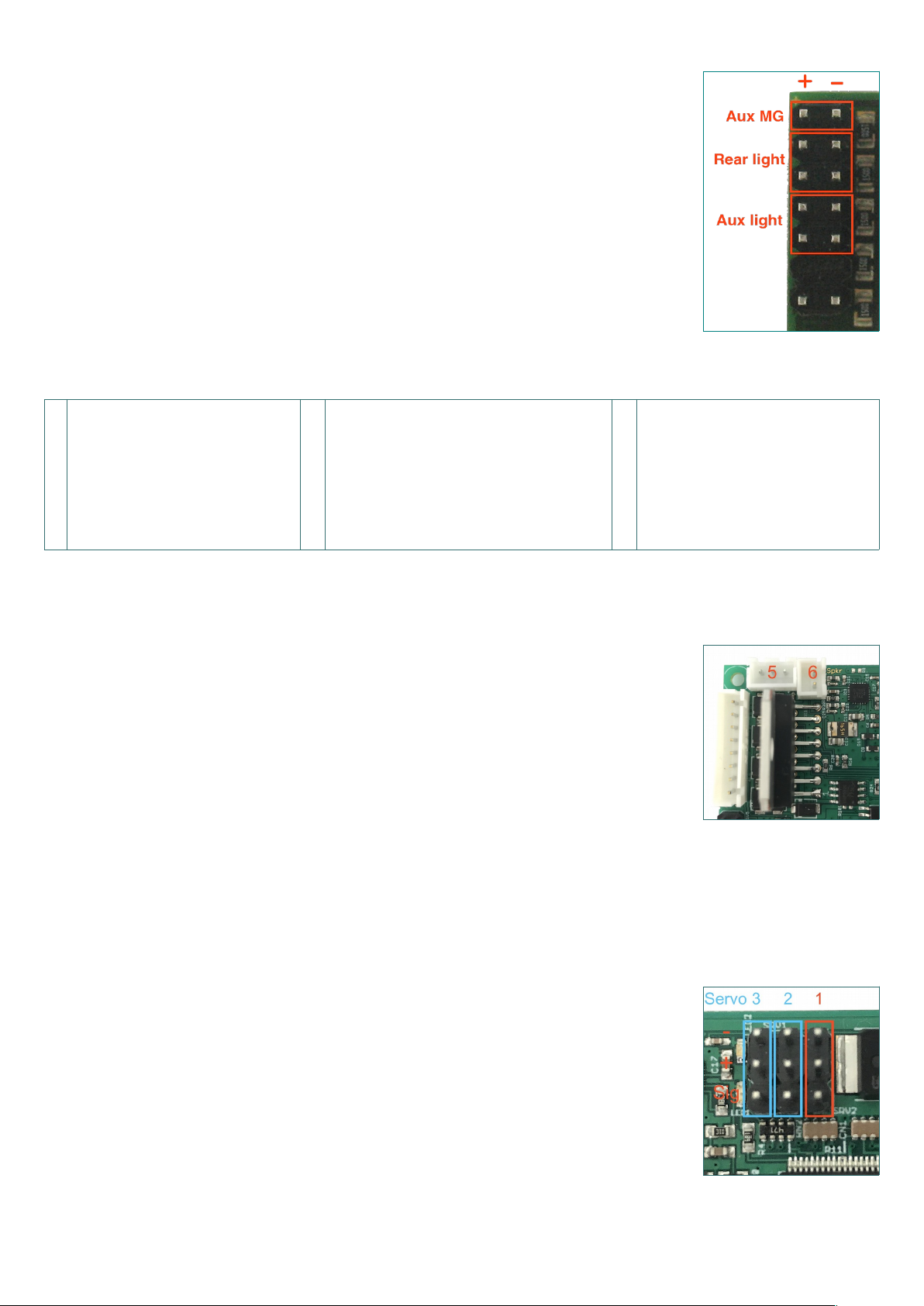
• ElMod Fusion Pro provides further light sources:
• one ultra bright white LED for muzzle flash of the auxiliary MG
• one or two red LEDs for combined rear and brake lights. The rear light is controlled together with the
front light. The brake light is active independently of the state of the main/rear light.
• one or two white LEDs for auxiliary light (e.g. camo light)
All light outputs are short circuit protected and current limited.
Pin assignment
Turret (connector 1) Muzzle flash (connector 2) Battle (connector 3)
from top from left von links
o
o
o
o
o
o
o
o
motor turret rotation
motor turret rotation
motor elevation
motor shot
common motor elevation and shot
Light common +
main light muzzle flash MG -
o
o
o
o
o
not used
not used
power supply – (LED and xenon flash)
signal + (LED and xenon flash)
power supply + (xenon flash only!)
o
o
o
o
o
signaling LEDs cathode
sensor signal
ground
IR sender cathode
+5V power supply
Sound: installation and connection
• plug the provided volume rotary knob to connector 5
• the ElMod Fusion PRO also provides the option to control the main volume by the radio. To activate
this feature the appropriate parameter has to be set in the ElMod App to "external" (tab "sound
volume", parameter "main volume control"). In this case the volume control knob on connector 5 will
be deactivated.
• connect the loudspeaker's cable with the output of a suitable 8 Ohm loudspeaker (connector 6). The
loudspeaker's polarity (+/-) makes no difference at this. We recommend the Visaton® FRS7-8 speaker
(loud, high pitch) or Visaton® FRS8-8 (quieter, lower/deeper pitch)
• for the best possible sound experience install the loudspeaker in an insulated airtight chassis with as
large volume as possible
• check the correct fitting of the micro SD card. If the card is not well fitted or its contents is faulty, the
sounds cannot be played.
• connect a fully charged battery to the ElMod Fusion and wait 3-4 sec. until the blue LED starts blinking constantly
• now tap the setup button. The call "battle mode..." is played. Tap several times more on the setup button until you hear "battle
mode off".
• if you cannot hear the call, please check if the volume is set too low
Servos
Depending on the type of your ElMod Fusion one servo (ElMod Fusion ECO) or three servos (ElMod
Fusion PRO) may be driven. The servos are power supplied by the board. The maximum current is 0,8 A
(ElMod Fusion ECO) or 1,5 A (ElMod Fusion PRO). The servos are connected so that the ground line
points to the upper edge of the PCB (see image).
Each servo may be assigned to one of the functions listed below. The same function may be assigned to
several servos simultaneously but every instance of this function may be configured independently (e.g.
for the control of three steering axles of a truck with different steering lock angle). For each function the
servo lock angle may be reversed or limited (right and left side separate). This is useful if the attached
mechanic has a smaller movement clearance as the servo's side arm). By two other parameters each
function may be further adjusted (see table).
- 4 - © ElMod - 19-09-02

function
module
type
effect param 1 (0-100%) param 2 (0-100%)
barrel recoil ECO/PRO barrel recoil after firing the main gun retraction speed extraction speed
steering ECO/PRO steering axle
speed dependent
steering lock angle (0% -
off, 100% - no steering
on max. speed)
-
elevation PRO
vertical movement of the main gun. The larger the stick
deflection the faster the movement
max. speed
elevation,
modern
PRO
as above. After each shot the barrel moves to the reload
position
max. speed
duration of reloading
in 0.1 secs
traversion PRO
horizontal movement of the main gun. The larger the
stick deflection the faster the movement
max.speed
turret
rotation
PRO turret rotation with an external ESC - -
hatch
function
PRO
simulation of an open/close function. On: servo moves
to the end position. Off: servo moves to the origin
position
opening speed closing speed
radar/wiper
function
PRO
wipe function. On: servo moves between both end
positions, Off: servo moves back and remains in the
starting position
speed of the "to"
movement
speed of the "fro"
movement
The hatch and radar function are auxiliary functions that are activated by the special functions on the radio (see chapter "function
control"). E.g. the commander's hatch may be attached to servo 1, AA radar to servo 2 and the driver's hatch to servo 3, the functions
are triggered as follows:
• switch on channel 5 must be positioned to auxiliary functions
• left lever to the left for activation/deactivation of the first servo's function (commander's hatch)
• left lever to the top for activation/deactivation of the second servo's function (radar)
• left lever to the right for activation/deactivation of the third servo's function (driver's hatch)
IR battle functions
The ElMod Fusion provides a Tamiya® Battle Unit compatible battle function. The configuration takes by tapping on the setup button.
Each tap changes the currently active setting which are:
• "battle mode light tank"
• "battle mode middle tank"
• "battle mode heavy tank"
• "battle mode test setting". If active, you may trigger a hit by nearly any infrared remote control.
• "battle mode off". This setting should be selected, when you do not use the battle function.
The selection of the vehicle's type affects its behavior during the battle. These features are listed in the following table:
setting
Hit count Time in seconds
Mushroom blinks
after power up
slight slow
down*
strong slow
down*
destruction
reload
time
invulnerability
after a hit
delay until
resurrection
test mode 1 3 6 3 2 5 4x
light 1 2 3 3 15 15 1x
middle 1 4 6 5 12 15 2x
heavy 1 5 9 9 10 15 3x
* reduction of the maximum velocity of the vehicle
The ElMod Fusion indicates specific events with four sounds:
• a fanfare after switching on with activated battle function and after each resurrection. The vehicle stays invulnerable for several
seconds (see table: reload time).
• reloading sound. Until this sound is heard you cannot fire again.
• metal impact after a hit. The vehicle stops and cannot be operated for two sec.
• an explosion during vehicle's destruction. The vehicle cannot be operated for the interval shown in the table (delay until
resurrection).
- 5 - © ElMod - 19-09-02
 Loading...