

Page 1
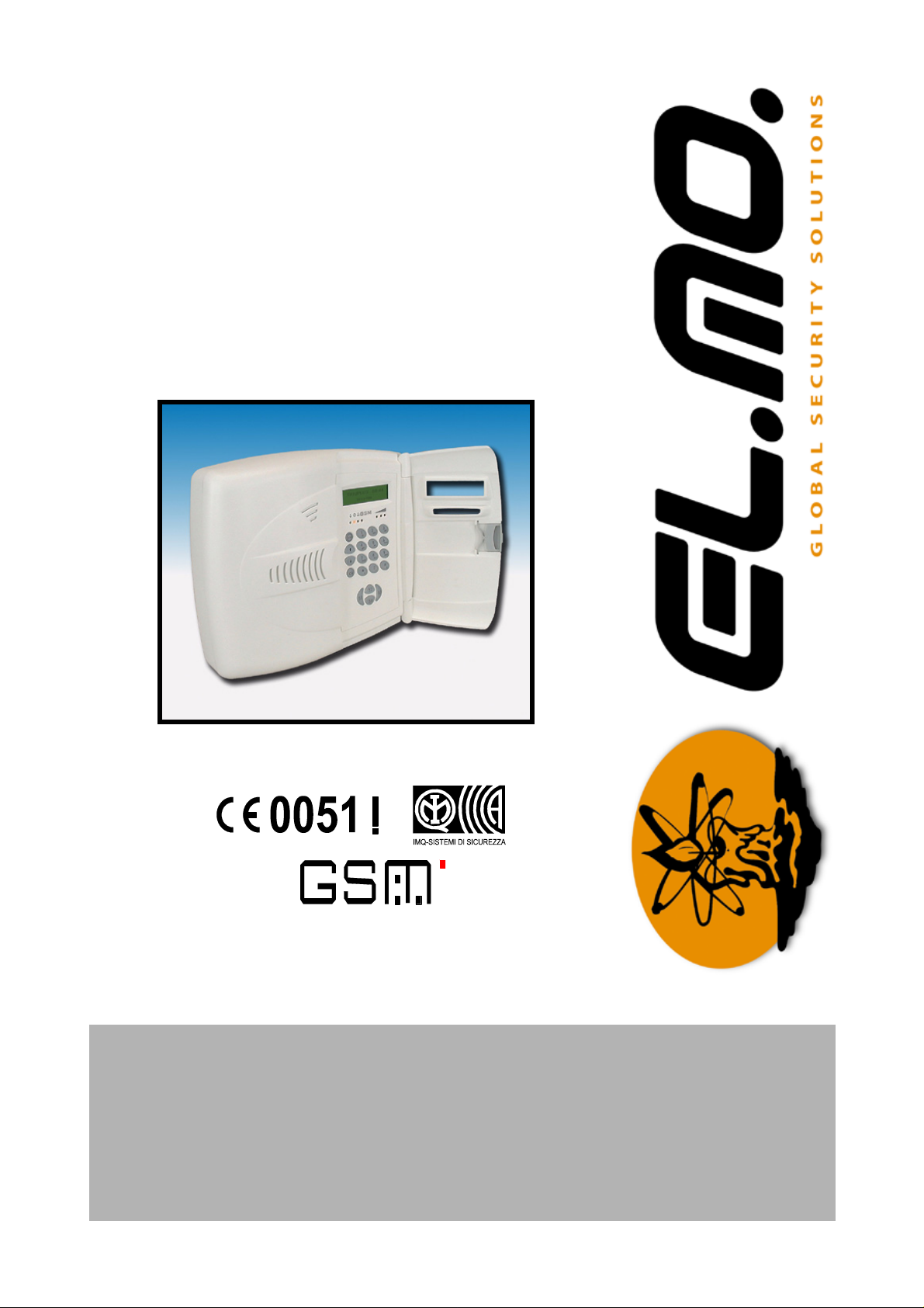
Telephone Diallers
TRH Series
USER MANUAL
Page 2

FOREWORD
FOR THE INSTALLER:
Please follow carefully the specifications relative to electric and security systems realization further to the manufacturer’s prescriptions indicated in the manual provided.
Provide the user the necessary indication for use and system’s limitations, specifying that there exist precise specifications and different safety performances levels that should b e proportioned to the us er needs. Have the user view
the directions indicated in this document.
FOR THE USER:
Periodically check carefully the system functionality making sure all enabling and disabling operations were made correctly.
Have skilled personnel make the periodic system’s maintenance. Contact th e install er to verify correct system operation in case its conditions have changed (e.g.: variations in the areas to protect due to extension, change of the access modes, etc…)
......................................................
This device has been projected, assembled and tested with the maximum care, adopting contro l procedures in accordance with the laws in force. The full correspondence to the functional characteristics is given exclusively when it
is used for the purpose it was projected for, which is as follows:
Telephone Diallers
Any use other than the one mentioned above has not been forecasted and therefore i t is not possible to guarantee
its correct operativeness.
The manufacturing process is carefully controlled in order to prevent defaults and bad functioning. Nevertheless, an
extremely low percentage of the components used is subjected to faults just as any other electronic or mechanic product. As this item is meant to protect both property and people, we invite the user to proportion the level of protection
that the system offers to the actual risk (also taking into account the possibility that the system was operated in a degraded manner because of faults and the like), as well remi nding that there are precise laws fo r the design and assemblage of the systems destinated to these kind of applications.
The system’s operator is hereby advised to see regularly to the periodic maintenance of the system, at least
in accordance with the provisions of current legislation, as well as to carry out checks on the correct running
of said system on as regular a basis as the risk involved requires, with particular reference to the control unit,
sensors, sounders, dialler(s) and any other device connected. The user must let the installer know how well
the system seems to be operating, based on the results of periodic checks, without delay.
Design, installation and servicing of systems which include this product, should be made by skilled staff with the necessary knowledge to operate in safe conditions in order to prevent accidents. These systems’ installation must be
made in accordance with the laws in force. Some equipment’s inner parts are connected to electric main and therefore
electrocution may occur if servicing was made before switching off the main and emergency power. Some products
incorporate rechargeable or non rechargeable batteries as emergency power supply. Their wron g connection may
damage the product, properties and the operator’s safety (burst and fire).
Your dealer:
2 - TRH Series - USER MANUAL
Page 3

1. USER INTERFACE
The TRH-series telephone diallers user interface consists of one LCD display, several signalling LEDs, a
20-key keypad, and a buzzer for acoustic signalling.
1.1 The LCD display
During normal operation the LCD display shows the TRH model, the internal clock time and th e dialler arming status. When a new event is generated, the display shows the event information for one minute, then the
normal status visualization is restored.
The LCD display has also an integrated backlight, which can be turned on by pressing any key and is automatically turned off after one minute has elapsed with no key pressed.
1.2 Status LEDs
TRH has 4 LEDs for status signalling located near the LCD bottom left corner. These LEDs give information
on: arming permission (green LED), anomaly status (yellow LED), alarm status (red LED) and GSM registration
status (red LED).
• Arming permission LED
The first LED (green) shows the TRH arming permission and can take three different states with the following meaning:
turned ON - arming permission granted (all zones on idle)
turned OFF - arming permission denied (at least one alarmed zone outside entry/exit path)
BLINKING - arming permission granted (all zones outside entry/exit path on idle, at least one alarmed
zone in entry/exit path)
Use the quick access menu to check for alarmed zones.
• Anomaly LED
The second LED (yellow) shows the anomaly status and can take the following states:
turned ON - no anomalies
BLINKING - at least one anomaly (or anomaly memory)
Use the quick access menu to check for anomalies.
• Alarm LED
The third LED (red) shows the dialler alarm status and can take the following states:
turned on - no alarm or alarm memory
SLOW BLINK - alarm memory
FAST BLINK - communication in progress
Use the quick access menu to check for alarm memories.
• GSM registration LED
The fourth LED (red) shows the GSM registration status and can take the following states:
turned OFF - GSM registered and ready
SLOW BLINK - GSM registered and ready, low signal strength
turned ON - GSM not registered on the network (off-line)
Use the quick access menu to check the GSM signal strength.
TRH Series - USER MANUAL - 3
Page 4

1.3 RF level signalling LEDs (TRH/Plus only)
On the right of the status LEDs (on the TRH/Plus model o nly) there are three LEDs that show the RF signal
level received from sensors and remote controls. The LEDs colors are red, yellow and green and they turn on
when an RF communication is detected showing the RF signal strength (respectively: low level, medium level
and high level).
2. THE QUICK ACCESS MENU
The quick access menu can be used to check the dialler status without having to insert the user code.
To enter the quick access menu, press the up-, or down-arrow keys when the dialler is in the normal visualization mode. When TRH is displaying an event on the LCD press STOP to switch back to the normal visualization mode.
Once entered the quick access menu, the display shows the "GSM SIGNAL" writing followed by the menu
browsing keys (up-arrow, down-arrow, OK, STOP).
The quick access menu has 5 sub-menus that can be selected with the arrow keys: GSM SIGNAL, ALARM
MEMORY, ANOMALY MEMORY, ZONE STATUS, SYNOPTIC STATUS. Press OK to enter the selected
menu.
During the visualization of the quick access menu the status LEDs blink fast and show the selected option
(the anomaly LED for anomaly memory, the alarm LED for alarm memory and the GSM LED for GSM signal
strength).
Press STOP to exit the quick access menu and switch back to the normal visualization mode.
2.1 GSM signal
This sub-menu allows to check the received GSM signal strength. The signal strength is displayed as a series of # characters growing from left to right. An indication equal to, or less than 4 positions corresponds to a
low signal strength.
Press OK to exit or press STOP key to switch back to the quick access menu.
2.2 Alarm memory
The alarm memory sub-menu allows to check such memories, if any. If more than one alarm memory is
present use the arrow keys to scroll all the memories.
Pres OK to delete all alarm memories.
Press STOP to switch back to the quick access menu without deleting the memories.
2.3 Anomaly memory
Anomaly memories can be checked from anomaly memory sub-menu. The memory checking pr ocedur e is
the same as the one seen above for alarm memories.
Press OK to delete all anomaly memories.
Press STOP to switch back to the quick access menu without deleting the memories.
If it is not possible to delete a memory then the anomaly cause is still present.
2.4 Zone status
The zone status sub-menu allows the user to check for alarmed zones. If more than one zone is alarmed,
use the arrow keys to scroll all alarmed zones.
Press OK to switch to normal visualization.
Press STOP to switch back to the quick access menu.
4 - TRH Series - USER MANUAL
Page 5

2.5 Synoptic status
From the synoptic status menu is possible to check the status of all zones simultaneously. The upper row
displays the zone number (from 1 to 16), while the lower row shows the actual status for each zone. The zone
status is shown using a single character:
' - ' means that the zone is on idle
' A ' means that the zone is on alarm
' M ' means that the zone is on tamper
Press OK to switch to normal visualization.
Press STOP to switch back to the quick access menu.
3. THE USER MENU
TRH has a configuration area reserved to the user and called User Menu. To access the user menu enter
the 6-digit user code and press the asterisk key. The factory value for the user code is "111111", so, to access
the user menu, type:
1 1 1 1 1 1 *
WARNING: typing the user code followed by OK is used to arm and disarm the dialler (see
below).
NOTE: if the dialler is in Panel Mode and armed it is necessary to disarm the dialler before entering the user
menu.
The user menu has 8 sub-menus that can be selected with the arrow keys in the same way as seen for the
quick access menu: EVENT HISTORY, CLOCK SETUP, ANOMALY BEEP, OUTPUT CONTROL, AIR TIME
BALANCE, "FOLLOW ME" NUM., USER CODE, REMOTE CTRL CODE.
3.1 Event history
The event history is an internal archive where TRH stor es al l the events gene ra te d during th e normal functioning. The event history can store up to 256 events, when the history log is full, older events will be deleted
to make room for new events.
Events are stored in the history log according to the order they are generated, and progressive numbers
ranging from 1 (for the oldest event) to 256 (for the latest event) will be associated to each of them. It is necessary to use the arrow keys to scroll all events stored into the history memory.
Events are displayed on two rows: the upper row shows the event description while the lower row contains
either the event parameter or information about the event number and generation time. The asterisk ( * ) and
hash ( # ) keys can be used to switch the visualization between the parameter and the number/time information.
Events with no parameters are always shown with number and time information.
Since TRH has a 24 hour clock, a "New Day" event is generated every midnight. To know how many days
have passed since a certain event happened, it is necessary to count all new day events generated after the
relevant event.
Press STOP to exit the menu.
3.2 Clock setup
From this sub-menu it is possible to set-up the internal clock, it is sufficient to enter the desired value and
press OK to confirm or STOP to cancel. The S1 and S3 keys can be used to move the cursor to the left or to
the right.
TRH Series - USER MANUAL - 5
Page 6

3.3 Anomaly beep
TRH can be programmed to generate an acoustic signal when an anomaly is detected. In this case TRH
plays a short beep every 15 seconds. By disabling the anomaly beep the user can stop the possible disturbance in case of persistent anomalies.
To switch between "yes" and "no" options, press OK. Press STOP to exit the menu.
3.4 Output control
From this sub-menu the user can control TRH programmable outputs. Press the arrow keys to select the
desired output, then press OK to flip the output state.
Press STOP to exit the menu.
3.5 Air time balance
TRH can read the air time balance for prepaid SIM cards. This functionality is only valid for italian Vodafo ne
and TIM cards. TRH shows the ??? writing when the air time balance is not available.
Press STOP to exit the menu.
3.6 "Follow me" number
From this menu the user can change the "follow me" telephone number (corresponding to the first entry in
the phonebook programmed by the installer). As an example, this functionality can be used to change a telephone number when the user leaves his house to go to a va cation place. By chan gin g the "follow me" n umber
TRH will call the appropriate number following the user's movements.
The "follow me" number has a maximum length of 20 digits.
TELEPHONE NUMBER EDITOR
Key Description
0, 1… 9 Inserts the specified digit under the cursor. A number can't be longer than 20 digits.
*, # Inserts the asterisk and hash characters.
Ç
S1
S3
S2
S4
OK
STOP
Inserts a 2-second pause ' P '.
Moves the cursor to the left.
Moves the cursor to the right.
Switches between the insert and overwrite modes.
Deletes the character under the cursor.
Stores the number into the internal memory.
Cancel any modification.
NOTE: to completely delete a number, move the cursor to the left and press the S4 key several times.
3.7 User code
To change the user code enter this menu and type the new 6-digit user code twice.
Press STOP to cancel the operation.
3.8 Remote control code
To change the remote control code follow the same procedure used to change the user code. The remote
control code is used to validate the user for SMS (text message) remote control and interrogation.
NOTE: setting the remote control code to 000000 disables all remote control and interrogation functionalities.
6 - TRH Series - USER MANUAL
Page 7

4. CHANGING THE ARMING STATUS
The installer has to enable the specific option to allow arming status changes.
4.1 Changing the arming status from keypad (TRH/Combi e TRH/GSM)
To change the TRH arming status from the keyp ad the u ser must type the user code followed by OK, if the
dialler is disarmed it will be armed, if the is armed it will be disarmed.
WARNING: typing the user code followed by the asterisk key will allow user to enter the user menu as previously explained.
4.2 Changing the arming status from keypad (TRH/Plus)
To change the TRH arming status from the keypad the user mu st type the user code fo llowed by OK. If the
dialler is armed it will be disarmed. If the dialler is disarmed it will be armed after the user specifies the desired
sectors.
When TRH/Plus is armed from the keypad, the "Select Sectors" message will display asking the user to select the sectors to be armed. The sectors to be armed are selected or deselected by pressing the S1, S2, S3,
S4 keys; pressing a key select a sector if it was deselected, conversely, the sector is deselected if it was selected.
The arming command can be confirmed by pressing OK, otherwise TRH will execute the arming command
after 5 seconds are elapsed without any key being pressed.
To cancel the arming procedure press STOP.
4.3 Arming from remote control (TRH/Plus)
A Taurus-type remote control can be used to arm/disarm the dialler, if previously configured by the installer.
The total arming key arms all and only the sectors associated to the remote control.
The disarming key disarms all and only the sectors associated to the remote control.
The partial arming-1 key arms only the first sector associated to the remote control.
The parial arming-2 key arms only the second sector associated to the remote cont rol.
TRH Series - USER MANUAL - 7
Page 8

5. DIALLER STOP
Dialler activity (calls in progress) can be stopped entering the user code followed by OK key (in the same
way as the arming procedure), if any calls are in progress TRH will not arm and the active call and all pending
calls will be cancelled.
On TRH/Plus the user can also stop the dialler by pressing the disarm button on the Taurus remote co ntrol.
5.1 Stopping the dialler when called
The user can stop the dialler when receives a call if his telephone supports multi frequency (DTMF) tones.
The dialler can be stopped in two ways: Recall stop and Stop-all-calls.
5.1.1 Recall stop
With the Recall stop function the user tells TRH to stop calling him for communications related to the same
event that generated the call. TRH will proceed and call other users. This function is useful when TRH is programmed to call the same user several times for each event.
To activate the Recall stop function, press the key 5 on the telephone device du ring the r ecorded m essage
playback. If the command is accepted, TRH plays 4 confirmation beeps and cuts the communication off.
5.1.2 Stop-all-calls
Issuing a Stop-all-call command, the user tells TRH to stop all calls to all users for the same event that generated the call.
To activate the Stop-all-call function, press the key 0 on the telephone device during the recorded message
playback. If the command is accepted, TRH plays 4 confirmation beeps and cuts the communication off.
WARNING: in this way it is possible to stop all and only the calls related to the same event. Other calls,
related to different events, will not be stopped unless the user presses again the key 0 when receives one of
such calls.
8 - TRH Series - USER MANUAL
Page 9

6. REMOTE CONTROL AND INTERROGATION
TRH diallers can be remotely interrogated and controlled via SMS (text messages).
WARNING:
remote control and interrogation are disabled if the remote control code is set as 000000.
to be enabled to remote control the sender telephone number must be listed into the TRH
phonebook.
6.1 SMS syntax
Remote control and interrogation SMS (text messages) are case insensitive and must obey some syntax
rules in order to be accepted by TRH.
All remote control and interrogation messages must start with the writing:
C.XXXXXX
Where XXXXXX is the remote control code. The remote control code must always be followed by a a space.
Available commands are:
I.ON to arm
I.OFF to disarm
A.outputname to activate an output
D.outputname to deactivate an output
R.I to receive a zone report
R.U to receive an output report
R.C to receive a dialler report
R.T to receive a full report
NOTE: it is possible to send multiple commands with the same message as long as all commands are sep-
arated by spaces.
EXAMPLE:
C.123456 A.Output 1 D.Output 4 I.ON R.T
The above command activates the output named "Output 1", d eactivates the ou tput na me "Output 4 ", arms the dialle r
and asks for a full report.
6.2 Arming command - I.ON
The "I.ON" command arms the dialler, starting the exit time if necessary. The sender receives a confirmation
SMS containing the "TRH armed" text.
This command is valid only if TRH is working in Panel Mode otherwise the command is simply ignored. If
the command SMS does not contain any valid commands the sender receives an SMS containing the
"INVALID COMMAND!" text.
NOTE: this command arms all TRH/Plus sectors.
TRH Series - USER MANUAL - 9
Page 10

6.3 Disarming and dialler stop command - I.OFF
The "I.OFF" command disarms TRH, stopping any outgoi ng calls if necessary. The sende r receives a co nfirmation text message containing the "TRH disarmed" text.
If TRH is not configured in Panel Mode, this command stops all outgoing calls but does not disarm the dialler. In this case the sender receives a confirmation SMS containing the "TRH stopped" text.
NOTE: this command disarms all TRH/Plus sectors.
6.4 Output activate command - A.outputname
The "A.outputname" command activates the output named "outputname". The sender r eceives a confirmation SMS containing the "outputname activated" text.
6.5 Deactivate output command - D.outputname
The "D.outputname" command deactivates the output named "outputname". The sender receives a confirmation SMS containing the "outputname deactivated" command.
If the specified output is not configured as a state output, the command will be ignored.
6.6 Zone report command - R.I
This command allows the user to remotely interrogate TRH about zone status. TRH will reply sending one
or more SMS containing the available information.
The TRH reply is a list of "zonename zonestatus" writings separated by commas.
The zone report is sent only for configured zones and, in case of RF zones, only for alarm/restore or 24h
sensors.
EXAMPLE:
El.Mo. TRH: Zone 1 on idle, Zone 2 on alarm, Radio 9 on tampering, Radio 10 on flood alarm.
6.7 Output report command - R.U
This command allows the user to remotely interrogate TRH about output status. TRH will reply sending one
or more SMS containing the available information.
TRH will reply with is a list of "outputname outputstatus" writings separated by commas.
EXAMPLE:
El.Mo. TRH: Output 1 active, Output 2 not active, Output 3 not active, Output 4 on pulse
6.8 Dialler report command - R.C
This command allows the user to remotely interrogate TRH about dialler status. TRH will reply sending information about arming status, air time balance, external power status, dialler batter y status, phone line status,
supervision status for radio sensors, battery status for radio sensors and fault status for radio sensors.
The arming status is sent only if the dialler is wo rking in Panel Mode, the air time balance check is sup ported
only for italian Vodafone and TIM prepaid cards.
EXAMPLE:
El.Mo. TRH: TRH armed, mains power ok, battery ok, low radio battery
6.9 Full report command - R.T
The full report command "R.T" requests all above listed report commands. TRH will reply sending one or
more SMS containing all requested information for zones, outputs and dialler status.
10 - TRH Series - USER MANUAL
Page 11

7. NOTE
TRH Series - USER MANUAL - 11
Page 12

8. TABLE OF CONTENTS
1. User interface . . . . . . . . . . . . . . . . . . . . . . . . . . . . . . . . . . . . . . . . . . . . . . . . . . . . . . . . . . . . . . . . . . . . . . . . . . 3
1.1The LCD display . . . . . . . . . . . . . . . . . . . . . . . . . . . . . . . . . . . . . . . . . . . . . . . . . . . . . . . . . . .3
1.2Status LEDs . . . . . . . . . . . . . . . . . . . . . . . . . . . . . . . . . . . . . . . . . . . . . . . . . . . . . . . . . . . . . .3
1.3RF level signalling LEDs (TRH/Plus only) . . . . . . . . . . . . . . . . . . . . . . . . . . . . . . . . . . . . . . 4
2. The quick access menu . . . . . . . . . . . . . . . . . . . . . . . . . . . . . . . . . . . . . . . . . . . . . . . . . . . . . . . . . . . . . . . . . . 4
2.1GSM signal . . . . . . . . . . . . . . . . . . . . . . . . . . . . . . . . . . . . . . . . . . . . . . . . . . . . . . . . . . . . . . .4
2.2Alarm memory . . . . . . . . . . . . . . . . . . . . . . . . . . . . . . . . . . . . . . . . . . . . . . . . . . . . . . . . . . . .4
2.3Anomaly memory . . . . . . . . . . . . . . . . . . . . . . . . . . . . . . . . . . . . . . . . . . . . . . . . . . . . . . . . . .4
2.4Zone status . . . . . . . . . . . . . . . . . . . . . . . . . . . . . . . . . . . . . . . . . . . . . . . . . . . . . . . . . . . . . . . 4
2.5Synoptic status . . . . . . . . . . . . . . . . . . . . . . . . . . . . . . . . . . . . . . . . . . . . . . . . . . . . . . . . . . .5
3. The user menu . . . . . . . . . . . . . . . . . . . . . . . . . . . . . . . . . . . . . . . . . . . . . . . . . . . . . . . . . . . . . . . . . . . . . . . . . 5
3.1Event history . . . . . . . . . . . . . . . . . . . . . . . . . . . . . . . . . . . . . . . . . . . . . . . . . . . . . . . . . . . . .5
3.2Clock setup . . . . . . . . . . . . . . . . . . . . . . . . . . . . . . . . . . . . . . . . . . . . . . . . . . . . . . . . . . . . . . . 5
3.3Anomaly beep . . . . . . . . . . . . . . . . . . . . . . . . . . . . . . . . . . . . . . . . . . . . . . . . . . . . . . . . . . . . 6
3.4Output control . . . . . . . . . . . . . . . . . . . . . . . . . . . . . . . . . . . . . . . . . . . . . . . . . . . . . . . . . . . . 6
3.5Air time balance . . . . . . . . . . . . . . . . . . . . . . . . . . . . . . . . . . . . . . . . . . . . . . . . . . . . . . . . . . .6
3.6"Follow me" number . . . . . . . . . . . . . . . . . . . . . . . . . . . . . . . . . . . . . . . . . . . . . . . . . . . . . . . 6
3.7User code . . . . . . . . . . . . . . . . . . . . . . . . . . . . . . . . . . . . . . . . . . . . . . . . . . . . . . . . . . . . . . . . 6
3.8Remote control code . . . . . . . . . . . . . . . . . . . . . . . . . . . . . . . . . . . . . . . . . . . . . . . . . . . . . . . 6
4. Changing the arming status . . . . . . . . . . . . . . . . . . . . . . . . . . . . . . . . . . . . . . . . . . . . . . . . . . . . . . . . . . . . . . 7
4.1Changing the arming status from keypad (TRH/Combi e TRH/GSM) . . . . . . . . . . . . . . . . 7
4.2Changing the arming status from keypad (TRH/Plus) . . . . . . . . . . . . . . . . . . . . . . . . . . . .7
4.3Arming from remote control (TRH/Plus) . . . . . . . . . . . . . . . . . . . . . . . . . . . . . . . . . . . . . . . 7
5. Dialler stop . . . . . . . . . . . . . . . . . . . . . . . . . . . . . . . . . . . . . . . . . . . . . . . . . . . . . . . . . . . . . . . . . . . . . . . . . . . . 8
5.1Stopping the dialler whe n call ed . . . . . . . . . . . . . . . . . . . . . . . . . . . . . . . . . . . . . . . . . . . . .8
5.1.1. Recall stop . . . . . . . . . . . . . . . . . . . . . . . . . . . . . . . . . . . . . . . . . . . . . . . . . . . . . . . . . . . . . . . . . . . 8
5.1.2. Stop-all-calls . . . . . . . . . . . . . . . . . . . . . . . . . . . . . . . . . . . . . . . . . . . . . . . . . . . . . . . . . . . . . . . . . 8
6. Remote control and interrogation . . . . . . . . . . . . . . . . . . . . . . . . . . . . . . . . . . . . . . . . . . . . . . . . . . . . . . . . . . 9
6.1SMS syntax . . . . . . . . . . . . . . . . . . . . . . . . . . . . . . . . . . . . . . . . . . . . . . . . . . . . . . . . . . . . . . .9
6.2Arming command - I.ON. . . . . . . . . . . . . . . . . . . . . . . . . . . . . . . . . . . . . . . . . . . . . . . . . . . . .9
6.3Disarming and dialler stop command - I.OFF . . . . . . . . . . . . . . . . . . . . . . . . . . . . . . . . . . 10
6.4Output activate command - A.outputname . . . . . . . . . . . . . . . . . . . . . . . . . . . . . . . . . . . .10
6.5Deactivate output command - D.outputname . . . . . . . . . . . . . . . . . . . . . . . . . . . . . . . . . .10
6.6Zone report command - R.I . . . . . . . . . . . . . . . . . . . . . . . . . . . . . . . . . . . . . . . . . . . . . . . . .10
6.7Output report command - R.U . . . . . . . . . . . . . . . . . . . . . . . . . . . . . . . . . . . . . . . . . . . . . . 10
6.8Dialler report command - R.C . . . . . . . . . . . . . . . . . . . . . . . . . . . . . . . . . . . . . . . . . . . . . . . 10
6.9Full report command - R.T . . . . . . . . . . . . . . . . . . . . . . . . . . . . . . . . . . . . . . . . . . . . . . . . . 10
7. NOTE . . . . . . . . . . . . . . . . . . . . . . . . . . . . . . . . . . . . . . . . . . . . . . . . . . . . . . . . . . . . . . . . . . . . . . . . . . . . . . . . 11
8. TABLE OF CONTENTS . . . . . . . . . . . . . . . . . . . . . . . . . . . . . . . . . . . . . . . . . . . . . . . . . . . . . . . . . . . . . . . . . . 12
Telephone Diallers - TRH Series - USER MANUAL
August 2005 Edition
Product specifications as described above do not bind the manufacturer and may be altered without prior notice.
EL.MO. SpA
Tel. +39 0499203333 (R.A.) - Fax +39 0499200306 - Technical Ass. +39 0499200426 - www.elmo.it - info@elmo.it
 Loading...