

Page 1
VANDAL RESISTANT DOME CAMERA
INFORMATION
This equipment has been tested and found
to comply with the limits for Class A digital
device, pursuant to Part 15 of the FCC
Rules. These limits are designed to
provide reasonable protection against
harmful interference when the equipment
is operated in a commercial environment.
This equipment generates, uses, and can
radiate radio frequency energy and, if not
installed and used in accordance with the
instruction manual, may cause harmful
interference to radio communications.
Operation of this equipment in a
residential area is likely to cause harmful
interference in which case the user will be
required to correct the interference at his
own expense.
USER-INSTALLER CAUTION: Your
authority to operate this FCC verified
equipment could be voided if you make
changes or modifications not expressly
approved by the party responsible for
compliance to Part of the FCC Rules.
CAUTION
• Do not use any power supply other than
specified.
WARNING
TO REDUCE THE RISK OF FIRE OR
ELECTRIC SHOCK.
* The CAUTION label is attached on the
bottom of camera.
INSTRUCTION MANUAL
CAUTION
RISK OF ELECTRIC SHOCK
DO NOT OPEN
CAUTION : TO REDUCE THE RISK OF ELECTRIC SHOCK,
DO NOT REMOVE COVER (OR BACK).
NO USER SERVICEABLE PARTS INSIDE.
REFER SERVICING TO QUALIFIED SERVICE PERSONNEL.
The lightning flash with arrowhead symbol, within
an equilateral triangle, is intended to alert the user
to the presence of uninsulated "dangerous
voltage" within the product’s enclosure that may
be of sufficient magnitude to constitute a risk of
electric shock to persons.
The exclamation point within an equilateral
triangle is intended to alert the user to the
presence of important operating and maintenance
(servicing) instructions in the literature
accompanying the appliance.
TND4204VX
Page 2

1
IMPORTANT SAFETY INSTRUCTIONS
1. Read these instructions.
2. Keep these instructions.
3. Heed all warnings.
4. Follow all instructions.
5. Clean only with dry cloth.
6. Do not block any ventilation openings, install in accordance with the manufacturer's
instructions.
7. Do not install near heat sources such as radiators, heat registers, stoves or other apparatus
(including amplifiers) that produce heat.
8. Only use attachment/accessories specified by the manufacturer.
9. Unplug this apparatus during lighting storms or when unused for long periods of time.
10. Refer all servicing to qualified personnel. Servicing is required when the apparatus has been
damaged in any way, such as power-supply cord or plug is damaged, objects have been fallen
onto the apparatus, does not operate normally, or has been dropped.
Page 3
2
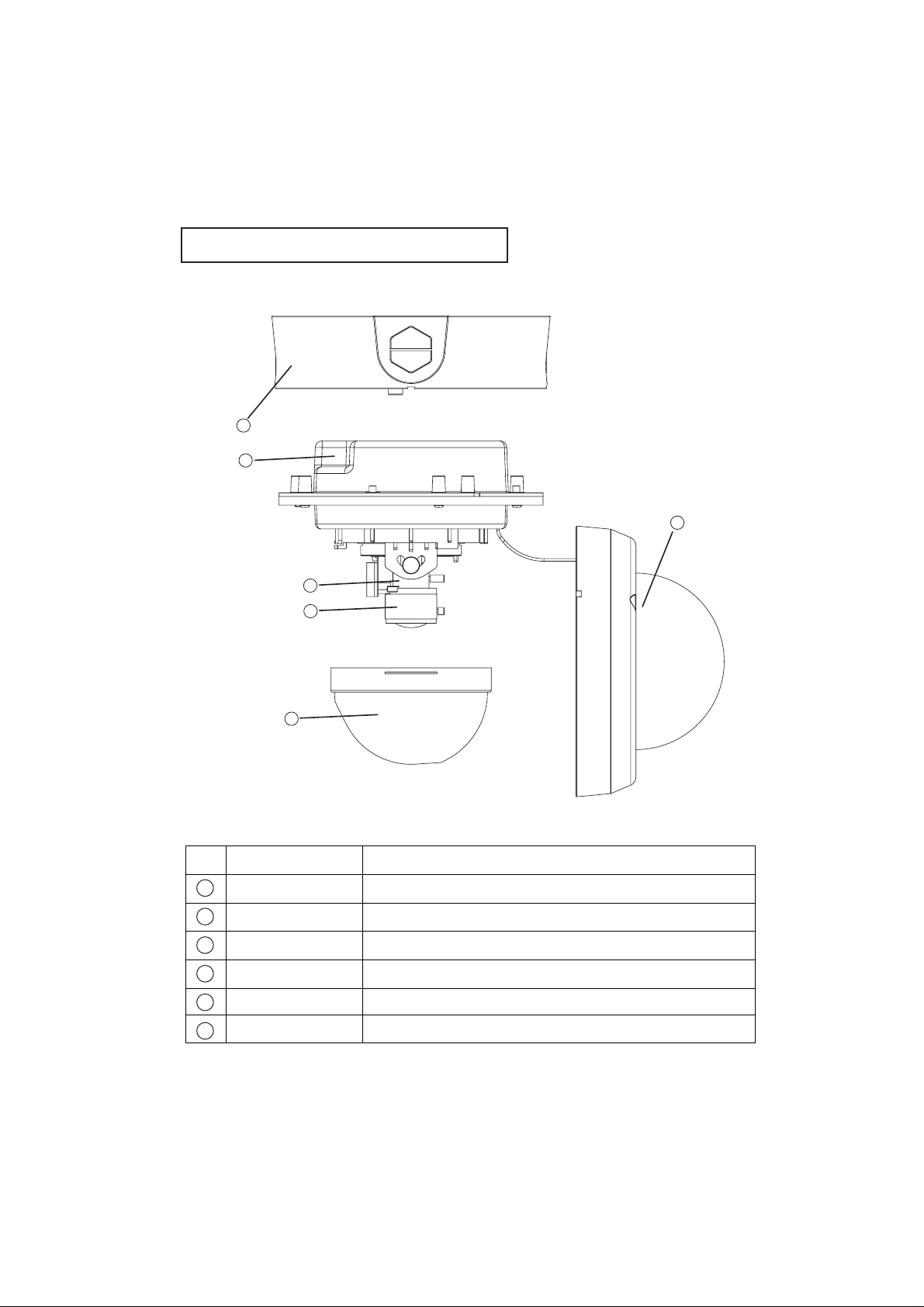
Name and Function of Each part
No.
Name Function
The mounting bracket for ceiling installation.
The main body of the camera section.
For adjusting the image size.
For adjusting the focus.
Protective cover for the lens.
Protective cover for the main body.
Camera mounting bracket
Main body
Zoom ring
Focus ring
Cover lens
Dome cover main body
1
2
3
4
5
6
1
2
3
4
5
6
Page 4
3
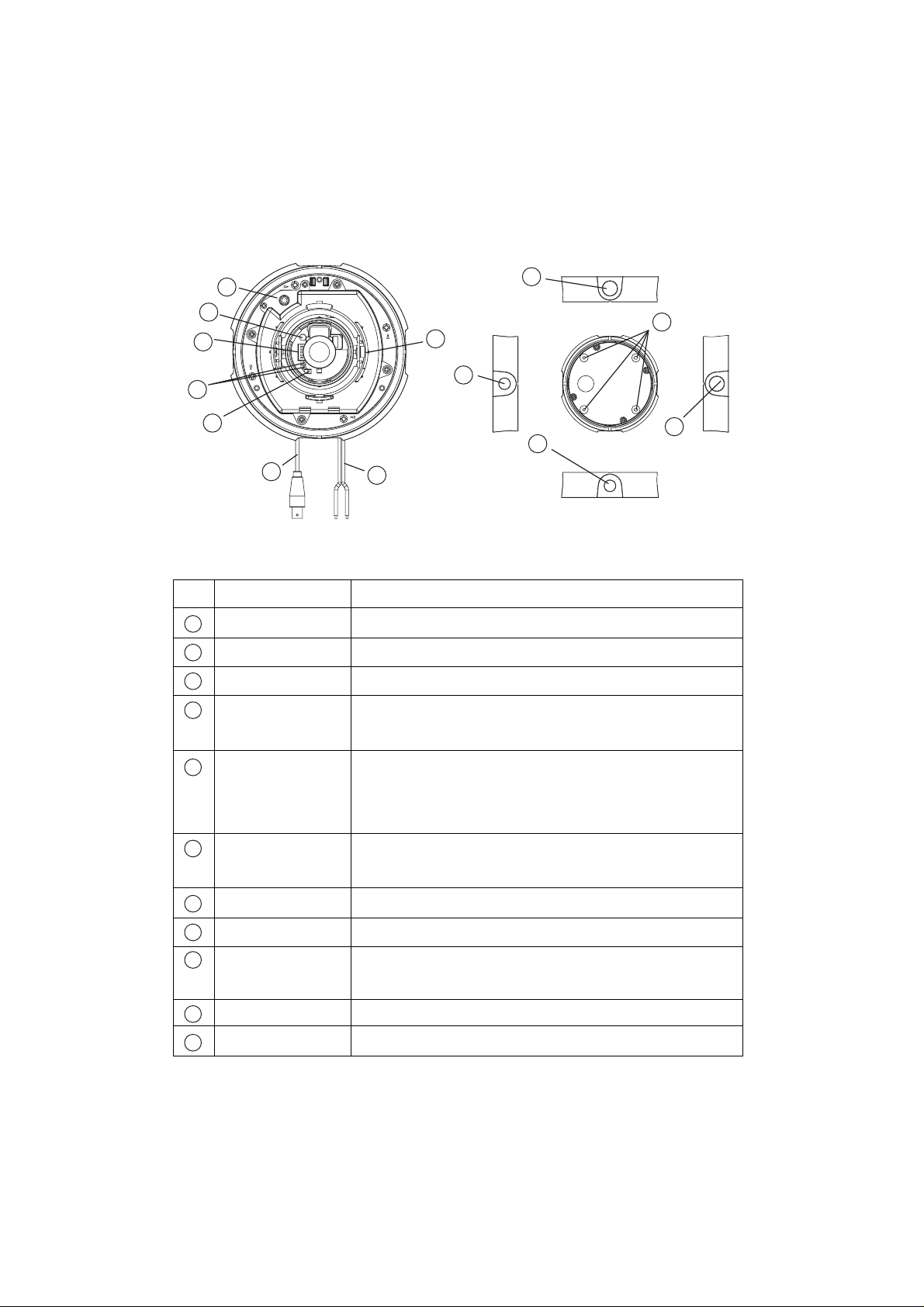
14
Used when the white balance is in the PUSH mode.
For setting the vertical sync. phase.
For adjusting the brightness of the image.
For locking the tilt after adjusting the image up/down
direction.
Connect this to output images. When adjusting the image
shooting direction, field angle or focus (in wiring work, for
example), connect a monitor TV, etc.
Image output terminal to be connected to the image input
terminal such as monitor TV.
Connect this to the AC24V 60Hz or DC12V power supply.
Refer to P4.[Selector Switch (Details)]
For fixing the camera mounting bracket with
screws.(Gang box)
Used when the wiring duct is connected.
Used when the wiring duct is connected.
No.
Name
Function
AW PUSH
DOWN/UP
ALC adjustment volume
Tilt lock screw
Monitor terminal
BNC cable
AC/DC power cord
Selector switch
Screw hole for
mounting bracket
Parallel pipe threads(G1/2)
Parallel pipe threads(G3/4)
17
16
15
11
9
17
15
10
10
11
8
16
7
17
16
12
7
8
9
13
12
13
14
Page 5

4
Selector switch (Details)
1.SENS UP switch
To set the max. value (upper limit value) of the
operating gain in the auto gain control circuit, set this
switch to ON position. In case the back lighting is too
dark and the camera sensitivity is insufficient, set this
switch to ON position.
2. BLC (Back Light Control) switch
In case the back lighting is too bright to view the
main object clearly, set this switch to ON position.
3. INT/LL switch(Set at LL position from the factory)
a. INT. (internal) control switch
When the internal synchronization is used, set the switch to the INT side.
b. L.L. (Line-lock) control switch
Matching the vertical synchronization with the power frequency is called the
line-lock.
When two or more cameras are connected to a monitor TV through a video
switcher, the vertical sync. phase can be locked with the power frequency, and
a stable vertical sync. is obtained without being disturbed at the time of
switching. Line-Lock is operative only when the AC24V 60Hz power supply is
connected.
Use Down/up Buttons to adjust the vertical sync. phase.
4. PUSH/ATW switch
This is the switch to select the white balance PUSH/ATW.
PUSH: When the lighting from the source is constant, it is possible to fix the AW
setting.
Place something white (paper, etc.) in front of the lens in a way that the
whole screen may be covered, then push the AW PUSH switch. At this
moment the setting is saved and retained even after the power is turned
OFF.
ATW: The camera automatically adjusts the white balance as it continuously
measures the color temperature of the lighting source.
5. 1/100s
When this switch is turned ON, the shutter speed is set to 1/100 second. It is
effective in reducing the light intensity.
Caution:
When this switch is turned ON, AES does not operate.
14
(This figure shows the setting
before shipment from our factory.)
5
1/100S
4
3
2
1
ON
PUSH/ATW
INT/LL
BLC
SENS UP
OFF
Page 6

5
How to Install
1. Make holes in the mounting surface.
(Fig. 1)
The paper pattern for installation is
included.
2. Remove the dome cover main body
fixing screws from the camera body.
(Fig. 2).
Use the dedicated wrench (Attached).
Be careful not to drop the cover
dome.
(Fig.2)
(Fig. 1)
Front of camera
Cover dome
screw
Dedicated wrench
(Attached)
Camera
mounting
bracket
Dome cover
main body
Page 7
6
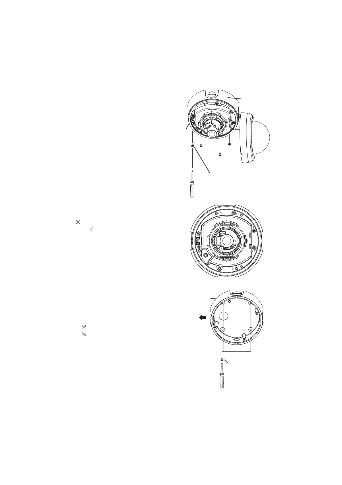
3. Remove the main body fixing screws,
and remove the main body from the
camera mounting bracket. (Fig. 3).
Remove the screws identified by the
mark(Figs. 4).
4. Fix the camera body to ceiling, wall or
box with the camera body fixing screws.
(Fig.5)
Make sure that it is fixed firmly.
Make sure of the position of the front
of the camera.
Main
(Fig.3)
(Fig.4)
(Fig.5)
body
Camera
mounting
bracket
Main body
mount screw
Camera
mounting
bracket
Front of
camera
Camera mounting
bracket mount
screw
(not attached)
Page 8

(Fig.7)
7
5. Connect the power cord and the BNC
cable, and then mount the main body on
the camera body. (Fig. 6).
· When you connect the Power cord and
the BNC cable, roll the waterproof tape
to prevent water damage as the figures
below indicate.
6. While watching the monitor, adjust the
image direction.
· Right/left direction (Fig.7)
Rotate the base pan to right or left, and
adjust the right/left direction.
· Up/down direction (Fig.8)
Loosen the tilt lock screw, and adjust
up/down direction.
After setting the up/down direction,
fasten the tilt lock screw.
(Fig.6)
Warning
Weight of the camera mounting
bracket and mounting metal
piece is 1600g(3.52lbs).
Make sure that the ceiling or wall
is strong enough to support the
weight of the camera mounting
bracket and mounting metal
piece altogether.If not strong
enough, the device may drop
and injure the personnel around.
Caution
Please do not hold a part of the
lens, when adjusting the image
direction. It may cause a
breakdown of the lens.
Power cord
BNC cable
Camera mounting bracket
BNC
cable
Power cord
Main body
Base pan
Lens
Page 9

8
Be careful not to drop the tilt lock
screw.
Manually fasten the tilt lock screw.
If fastened with pliers or the like, the
tilt lock screw may be broken.
7. Correct the image tilt. (Fig.9)
Be sure to hold the cover motor.
8. Mount the cover lens, and mount the
dome cover with the dome cover fixing
screws. (Fig.10)
(Fig.8)
(Fig.9)
(Fig.10)
Camera mounting bracket
Tilt lock screw
Lens
Cover motor
Lens
Main body
Dome
cover
Cover
lens
Page 10

9
)
)
Appearance
All dimensions in mm(inch)
When any failure is suspected
Symptoms
Image is not displayed.
Color is not correct.
Image is disarrayed.
Check here.
Are cables connected correctly?
Are the power plugs of peripheral units inserted correctly
into the receptacles?
Is the video monitor adjusted correctly?
Is any connector of this machine or video monitor loose or
contacted poorly?
166(6.54
101.6(4.00
Page 11

10
Specifications
Power source
Power consumption
Image pick-up device
Effective picture element
Scanning area
Scanning system
Scanning frequency
Sync.system
Resolution
S/N ratio
Standard illumination
Lowest illumination
White balance
AGC
Backlight control (BLC)
Electronic shutter
Power
VIDEO OUT terminal
Lens
Angle of view
Movable angle
Waterproof rating
Dimensions
Weight
Ambient temperature
Ambient humidity
Accessory
AC24V(AC15V-27V) 60Hz 0.5Hz or
DC12V(DC11V-35V)
AC : Approx.2.5W or DC : Approx.2.8W
1/3" color interline-transfer CCD
768(H) 494(V)
4.88mm(H) 3.66mm(V)
2:1interlaced
LL : 15.75kHz (H), 60Hz (V)
INT : 15.734kHz (H), 59.94Hz (V)
AC : Line-lock/Internal (switchable)
DC : Internal
480TV lines(H) 350TV lines(V)
50dB
60lx (F1.2 under incandescent lamp)
0.35lx (F1.2 under incandescent lamp)
ATW/PUSH (switchable)
Built-in (SENS UP switchable)
Provided (switchable)
1/60sec. / 1/100sec. (switchable)
Power cable (Non-plug)
BNC cable output VBS 1.0V(p-p) 75
Varifocal lens F1.2 f=3~9mm
Horizontal 31.8 (TELE)~90.0 (WIDE)
Vertical 23.9 (TELE)~68.2 (WIDE)
Pan 180 ( 90 ) / Tilt 120 ( 60 ) / Camera 290
IP66
Diameter : 166mm(6.54") Height : 128mm(5.04")
Approx. 1600g(3.52lbs)
-10 ~50 (14 ~122 )
30%~90%
Instruction manual, Registration certification card
Dedicated wrench, Paper pattern(for installation)
Model TND4204VX
Page 12

11
and are registered trademarks of ELMO COMPANY, LIMITED.
ELMO CO., LTD.
6-14, Meizen-cho, Mizuho-ku,
Nagoya, 467-8567 Japan
E-mail : foreign-div@elmo.co.jp
OVERSEAS SUBSIDIARY COMPANIES
ELMO Mfg. Corp.
1478 Old Country Road,
Plainview, NY 11803-5034
U.S.A.
Tel.
516-501-1400
Fax. 516-501-0429
E-mail:elmo@elmousa.com
Web:http://www.elmousa.com/
ELMO Canada Mfg. Corp.
44 West Drive, Brampton,
Ontario, L6T 3T6,
Canada
Tel.
905-453-7880
Fax. 905-453-2391
E-mail:info@elmocanada.com
Web:http://www.elmocanada.com/
6X1NSVA02 Printed on recycled paper
ELMO (Europe) G.m.b.H.
Neanderstr. 18
40233 Dusseldorf,
Germany
Tel.
0211-376051-53
Fax. 0211-376630
E-mail:elmoeurope@AOL.com
Web:http://www.elmo.de/
Printed in CHINA
 Loading...