

Page 1

8mm
SOUND
PROJECTOR
INSTRUCTION
MANUAL
Page 2

IMPORTANT
SAFEGUARDS
When
using
your
photographic
equipment,
basic
safety
precau-
tions should
always
be
followed,
including
the
following
1. Read and understand all instructions.
2.
Close
supervision
is
necessary when
any
appliance
is
used
by
or
near children.
Do
not leave
appliance
unattended
while
in
use.
3.
Care
must be taken as burns can
occur
from
touching
hot
parts.
4.
Do
not
operate
appliance
with a
damaged
cord
or
if the
appliance
has been
dropped
or
damaged-until
it has been
examined
by
a
qualified
serviceman.
5.
Do
not
let
cord
hang
over
edge
of
table
or
counter
or
touch hot
surfaces
.
6.
If an extension
cord
is
necessary, a
cord
with a suitable
current
rating
should
be
used.
Cords
rated
for
less
ampe-
rage
than the
appliance
may
overheat. Care
should be
taken to
arrange
the
cord
so that
it
will not be
tripped
over
or
pulled.
7.
Always
unplug
appliance
from 'electrical
outlet when not
in
use.
Never
yank
cord
to pull
plug
from
outlet.
Grasp
plug
and
pull to disconnect.
8.
Let
appliance
cool
completely
before
putting
awa
y. Loop
cord
loosely
around
appliance
when
storing.
9. To
protect
against
electrical
shock hazards,
do
not immerse
this
appliance
in
water
or
other liquid s.
1 O. To
avoid
electric shock haz
ard,
do
not disas semble this
appliance,
but take
it
to a
qualified
serviceman when some
service
or
repair
work
is
required.
Incorrect
reassembly
can cause electric shock haz
ard
when the
appliance
is
used
subsequently.
SAVE THESE
INSTRUCTIONS
Page 3
Contents
INTRODUCTION
NOMENCLATURE
PROJECTION
RECORDING
MAINTENANCE
HINTS
Two Tr
ack System .
Two Trac
k Recording and Playback Operation
• Track Selection
•
Ba
lance contro l
Preparing
For Project ion
Sound
Pr
ojection
........
..
. .
I m
age Adju stment
..
.
Rever
se
Projection.
Re
winding
the Film .
Re
mo
ving the Film During
Midway
Projection
Sound Op
tio
ns .
.....
....
........
.
...
.
• Extension Speak
ers
• Reproducing So
und
Through a Ster
eo Ampl
ifi
er
• Using
an
Earphone
or Headset
H
ow
to
Record on
Two Tracks
• M
onitor
Jacks
• I
nput
Jacks
• Double Recording
• Record Control
• Frame
Count
er
3
4
6
8
12
14
15
15
16
17
18
Norm
al Recording . . . . . . . . . . . . .
...
.. ..
25
Recording and Playback Advantag
es
of the Two Track System . . . . . . . . . . . . 26
Track Transfer . . . . . . . . . . . . . 28
• Conn ecti
ng
Cord
•
Ad
ju sting the I
nput Leve
l
Mixing
...
. . .
.....
......
30
Cleaning
...
31
• H
ow
to
Remove the Lens
Repl
ac
ing La
mp
.....
.
......
.
...
33
• Projection Lamp
•
Excit
er Lamp (Model M-O only)
Repl
ac
ing Fu
ses
. . .
35
• Main Power Fuse
•
Amplifi
er Fu
se
& Exc
it
er La
mp
Fuse
Voltag e Sel
ec
tion
..............
..
.
Troubl
e-shoot
ing
Hints ..
_ .
..•.
•
Option
al Acc essori
es
. _
........
.
Acc
esso
ry Cords
...
. .
Connection
Exa
mple ...
• Projection
Distance and I mage Size
• Projection
Tim
e and
Film
Length.
36
36
37
40
41
42
43
• Specification
s . _ . . . .
............
......
. . .........
44
Page 4

2
Thank you
for
selecting the Elmo ST·600D Sound Projector.
The
Elmo ST·600D
is
a high performance sound projector
capable
of
magnetic recording
and
playback on two
sound
tracks
as
well
as
playing back ready·made optical sound
film
(Model M·O).
What's more, this new
sound
projector features unlimited sound
recording
potentials including, dubbing capabilities which enable
the buildup
of
the most sophisticated sound tracks in the most
effortless manner.
Be
sure
to
carefully
read
through this instruction manual
to
make
the most
of
these
fascinating features
and
to
ensure
against improper
handling that may result in
damage.
Page 5

Track
1
(Main stripe)
INTRODUCTION
Two Track System
Track 2
(Balance
stripe)
As shown in
the
above
illustration,
8mm
sound
film
comes striped
with
magnetic coatings on
both
edges,
also
known
as
"magnetic
stripe."
The wide
or
"main"
stripe
is
used
to
carry the sound
track
when
used
in
conventional projectors. This sound stripe
will
be called Track 1 here-
after
in
this
manual.
The
narrow
or
"balance"
stripe,
that
runs
just
outside
the
film
perfo-
rations,
is
used
for
balance
to
ensure
smooth
film
travel
through
the
projector.
Though
Track 2 is
narrow
in
width,
it
is
coated
with
the
same
quality
magnetic
oxide
as
that
on
Track
1.
So,
the
Elmo ST-600D utilizes
both
the
main stripe and
the
balance stripe
for
recording and playback.
We
have designated this new sound system a
Two
Track
System.
After
receiving
your
sync-sound
film
from
the
processing laboratory,
there
will
most
likely
be
sound on
Track
1.
Music and
narration
can
be
added
to
the
balance
track
(Track 2)
to
accompany
your
original sound on
Track
1.
You
may record
on
Track 2 as
often
as
desired
or
until
you
are
totally
satisfied
with
the
mixed
recording. This
is
done
without
affecting the original sound
on
Track
1.
[If
the
film
does
not
come striped
with
a magnetic coating,
it
is
necessary
to
ask
your
nearest
photo
dealer
to
have
your
film
striped
when sending
it
in
for
processing.)
3
Page 6

4
Two
Track
Recording
and
Playback
Operation
Set
the
track
selector
in
the
correct
position
to
perform
the
following .
• Track Selection
BI
r~Jl
OJ~~
BI
r~n
OJL1iiIim~
BI
r~n
OJLIDrJ~
Position 1
• Select
position 1 to
record
or
playback
Track
1.
Position 2
• Select
position 2 to
record
or
playback
Track
2.
Position 1
+ 2
• Select
position
1 + 2
to
play
both
tracks
simultaneously.
Note: Both
tracks
can't
be
recorded
simultaneously.
Particularly
when
recording, be sure
to
select
the
correct
·
position
conform
ing
to
the
track
to
be used.
Erroneous
track
selection
may
resu
It
ir
undesirable erasure.
Page 7
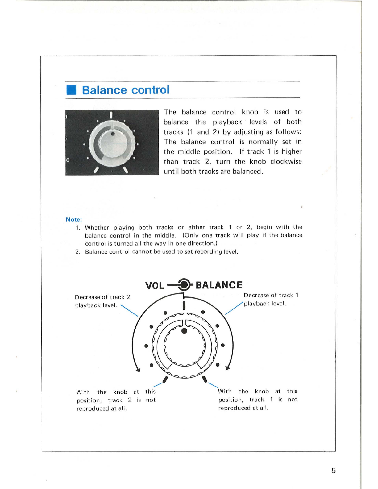
• Balance control
.:(j).
o I . \
Note
:
The balance
control
knob is
used
to
balance the playback l
eve
ls
of
both
tracks (1 and
2)
by adjusti
ng
as
follows
:
Th e balance
control
is
normally
set in
th
e middle position.
If
track
1 is high
er
than
track
2,
turn
the knob clockwise
until
both
tracks are balanced.
1.
Whether play
ing
both
tracks
or eith
er
track 1 or
2, begin
with
the
balance
contro
l in
the
mid
dle.
(On
ly one
track
will play
if the balance
co
ntrol
is
turn
ed all the
way
in
one
dir
ect
ion.)
2. Balance cont
rol cannot
be used
to
set
recording
leve
l.
VOL
-@r
BALANCE
Decrease
of
track
2
pla
yback
level.
~
With
the
knob
at this
pos
iti
on,
track
2 is
not
re
produc
ed
at
all.
Decr
ease
of
track
1
/
Pl
aYback leve
l.
the knob
at
this
position, track 1 is
not
re
produc
ed
at all.
5
Page 8

6
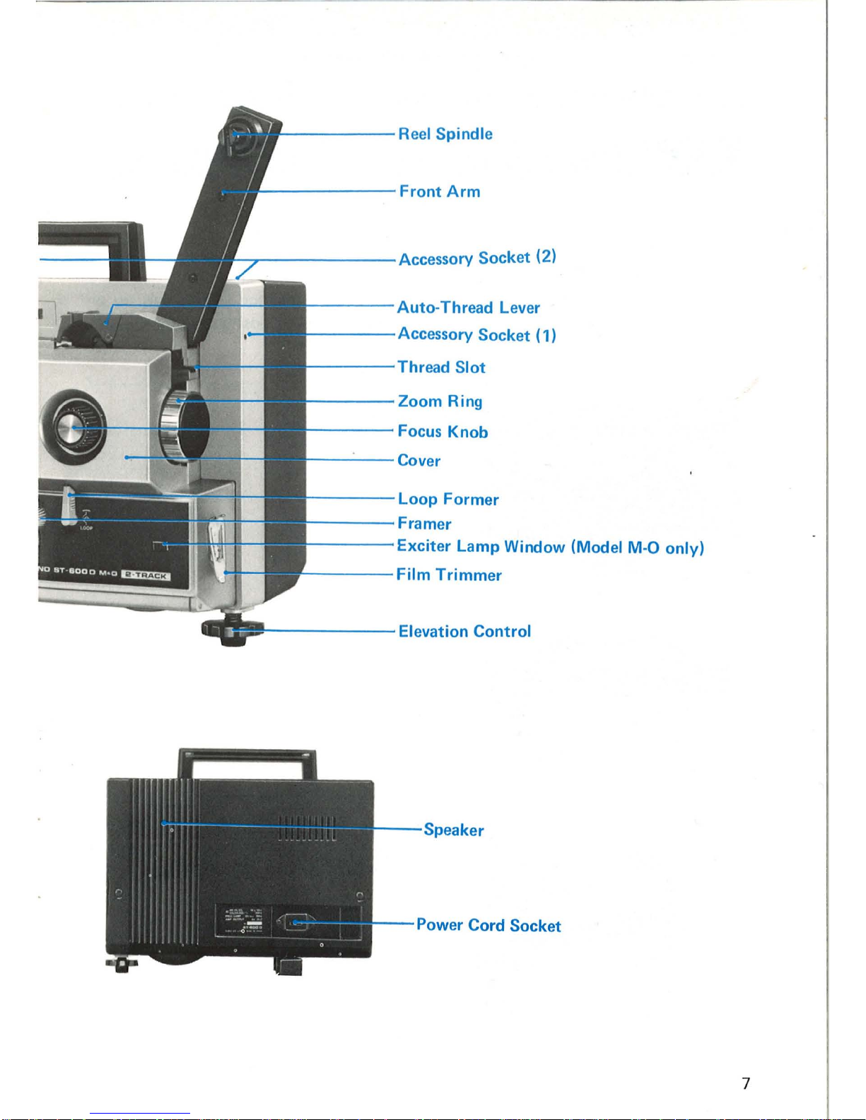
NOMENCLATURE
Reel
Lock--------------
~
RearArm------------------
Frame Counter
---------------
-1-
Green Monitor
Jack
2
----------
-+-
.....:;;;;....-,...
G ree n Mon itor
Jac
k 1
----------
--t---or-.
Record
Level Meter
---------------..:.
w:
::i:~!1
Record
Button
-------------
~.
Sound
Selector
(M-SILENT-
O)
(Model
M-O
only)
TrackSel~tolr
--
----
---------
Main Control Knob
Double Record Control
Volume Control
Knob---------...:
====:;fJ
~
Balance Control Knob----------------
J
Projection Speed Selector
Record Control
Button
MIC. Jack
-------
......
AUX.
IN
Jack
----...
Yellow Monitor
Jack
EXT.
SpeakerConnl'M,nr
----------
-T
--t
-H
Page 9
,.....
-----
Reel Spindle
'--------
Front Arm
---.
~------
Accessory
Socket (2)
f-----
Auto-Thread Lever
f---
- - Accessory
Socket
(1)
f-----
Thread Slot
----
Zoom Ring
----
Focus Knob
-
---
Cover
1-----
Loop Former
1-----
Framer
1-----
Exciter Lamp Window (Model
M-O
only)
-----
Film Trimmer
._
----
- - Elevation Control
Speaker
Power Cord Socket
7
Page 10
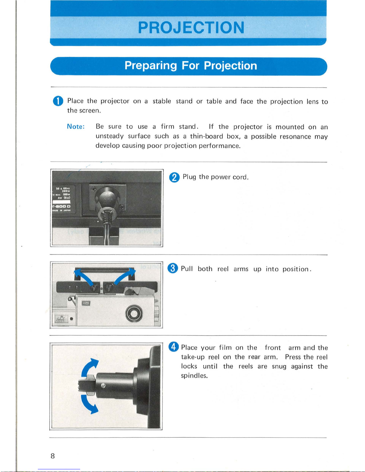
PROJECTION
Preparing For Projection
o Place
the
projector
on a stable
stand
or
table
and
face
the
projection lens
to
the scr
een.
Note:
8
Be
sure
to
use a
firm
stand.
If
the
projector
is
mounted
on
an
unsteady surf
ace
such
as a
thin-board
box, a possible
resonance
may
develop
causing
poor
projection
performance.
8 Plug
the
power
cord.
o Pull
both
reel
arms
up
into
position.
o Place
your
film
on
the
front
arm
and
the
take-up
reel
on
the
rear
arm.
Press
the
reel
lock
s until
the
reels
are
snug
against
the
spindles.
Page 11
___
+
__
Zoom
ring
---
+
--
Focus knob
....
______
-+
___
Elevation control
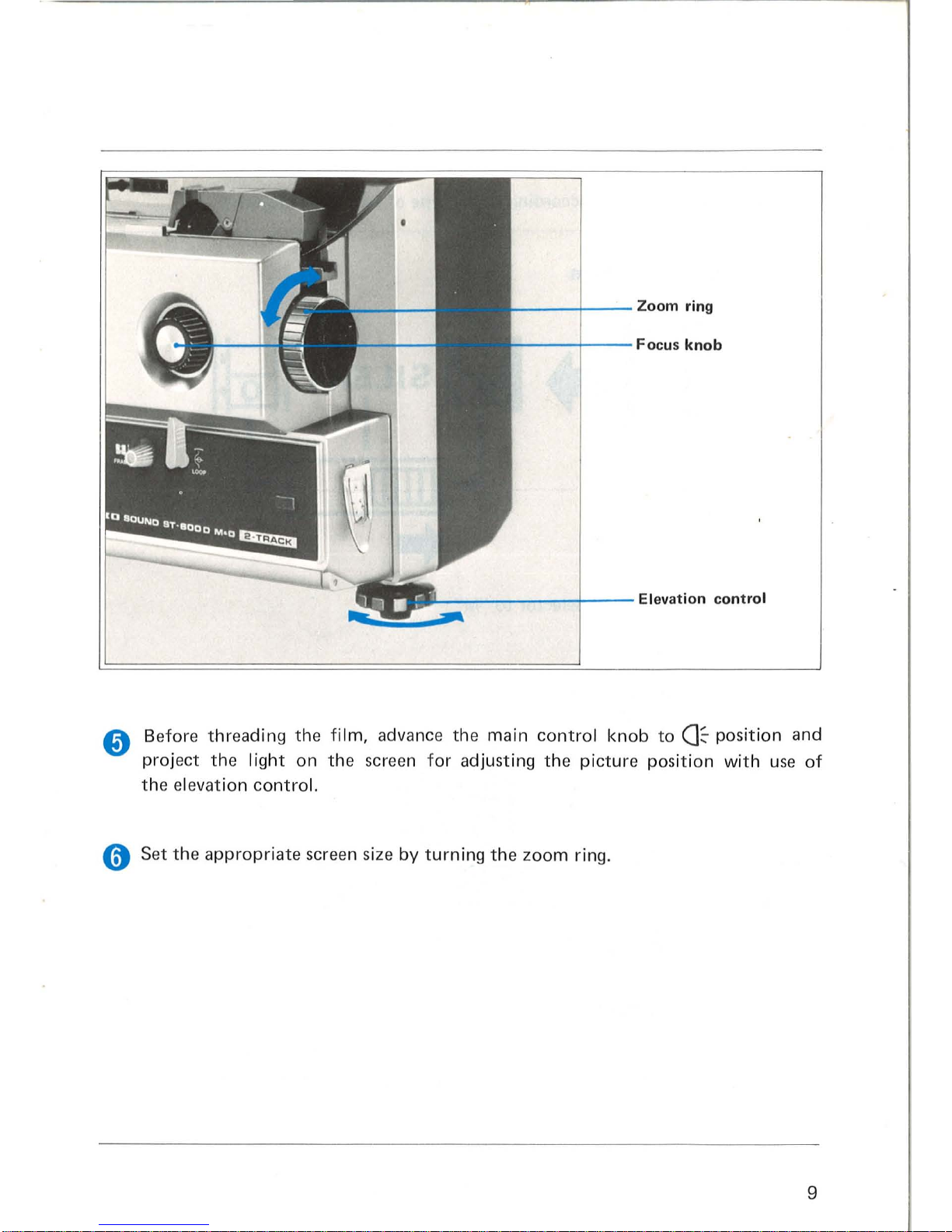
Before threading the
film,
advance the
main
control
knob
to
a~
position
and
project
the I ight
on
the scr
een
for
adjusting
the
picture position
with
use
of
the
elev
ation
control.
o Set
the
appropriate
screen size
by
turning
the
zoom ring.
9
Page 12

o
Select
the
sound
mode
acco
rding
to
the
type
of film
to
be
projected
.
Magnetic Sound Film
Set
the
Sound
Selector
to
"M"
o Select
the
Track
Selector.
·BI.
11+21
ITJ\
UIIIIIIJ
\[ID
Select
position 1 to
playback
Track
1.
Select
position 2 to
playback
Track
2.
Select position 1 + 2
to
playback
both
tracks simult
aneo
usly.
10
Page 13

Optical Sound Film (Model M-O only)
Projection
speed
selector
24
I
18
Set the
Sound
Selec
tor
to
"0".
S
et
the
Sound
Sel
ector to
"SILENT".
«;)
Sel
ect
the
proper
projection
speed, either
24
fps (UP) or
18
fps (DOWN).
Important:
Be
sure
the
motor
is
OFF
when changing pro -
jection
speed .
11
Page 14
Film
trimmer
Main
control
knob
12
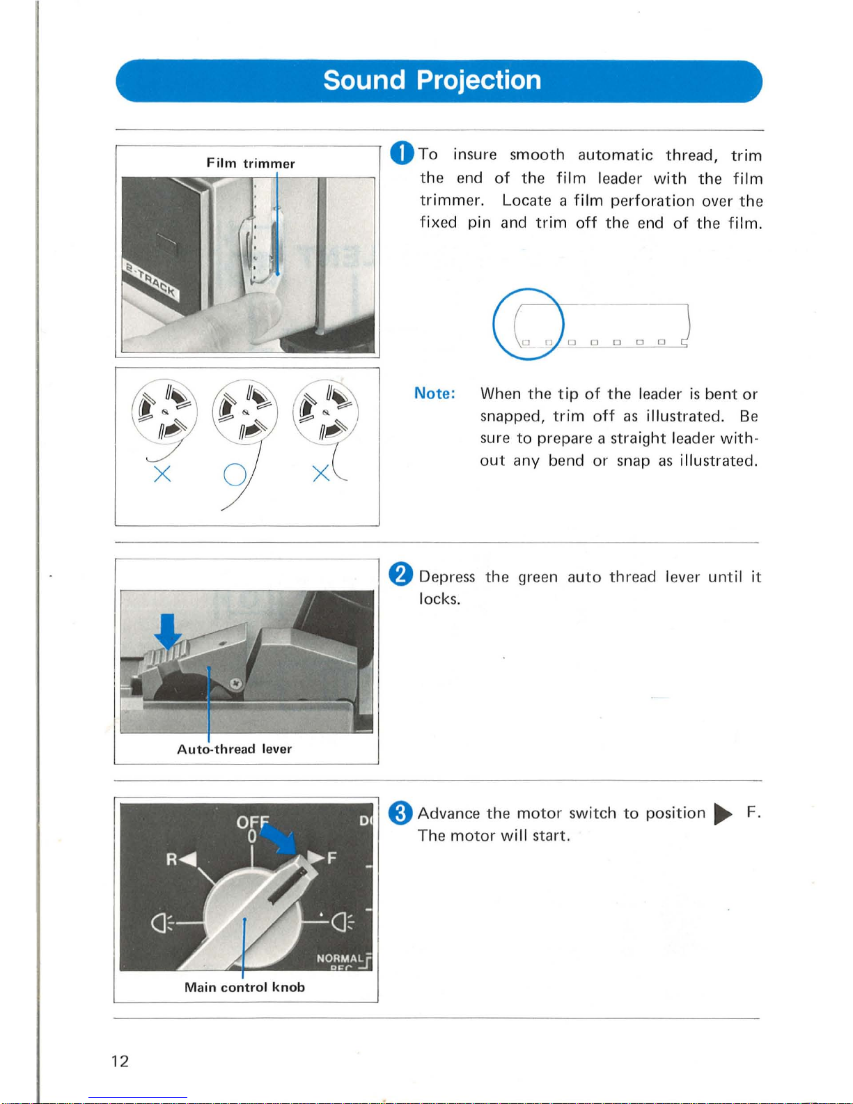
Sound Projection
o
To
insure
smooth
automatic
thread,
trim
the
end
of
the film
leader
with
the
film
trimmer.
Locate
a film
perforation
over
the
fixed
pin
and
trim
off
the
end
of
the
film.
Note:
When
the
tip
of
the
leader
is
bent
or
snapped,
trim
off
as
illustrated.
Be
sure
to
prepare a straight
leader
with-
out
any
bend
or
snap
as
illustrated.
8 Depress
the
green
auto
thread
lever
unti
l it
locks.
8
Advance
the
motor
switch
to
position
~
F.
The
motor
will
start.
Page 15
Volume
control
Balance
control
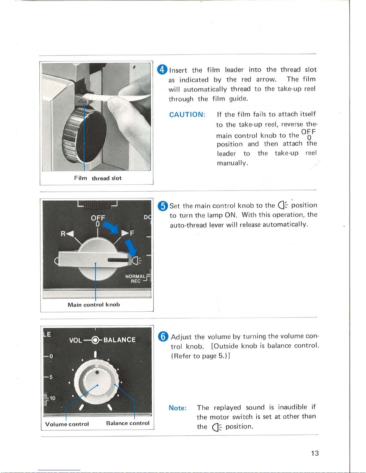
o Insert
the
film
leader
into
the
thread
slot
as
indicated
by
the red
arrow. The
film
will
automatica
lly
thread
to
the take-up reel
through
the
film guid
e.
CAUTION
:
If
the
film
fails
to
attach itse
lf
to
the
tak
e· up reel, reverse the'
main
control knob
to
the
°b
F
position
and then attach
the
leader
to
the
take·up
reel
manually.
o Set the
main
control
knob
to
the
C1~
position
to
turn
the
lamp ON. With
this
operation,
the
auto-thread lever
will
release
auto
mati cally.
o
Adjust
the
volume
by
turn
ing
the
volume con-
trol
knob. [Outside
knob
is
balance
contro
l.
(Refer
to
page
5.) 1
Note: The replayed sound is inaudible
if
the
motor
switch is set at
other
than
the
Ck
position.
13
Page 16

Image Adjustment
Zoom
ring
Framer
Loop
former
~
Adju
st
the
picture size
to
the
screen by
turning the zoo m ring.
[§J
Adju
st the
framer
to elimin
ate
frame lin
e.
[Q
Press the
loop
form
er
to res
tore the film loop
if
lost
during
projection
.
14
Note: When
the film
loop
is lost
during
projection,
check the
film'
s pe
rforation
s
and
s
plic
es
after
projection
is over.
Page 17

Reverse Projection
• Advance
the
main
control
knob
counterclock-
wise
to
the
CJ~
position.
Rewinding the Film
o
After
projection
is
finished,
wind
the
film
back
on
the feed
reel.
8 Advance
the
main
control
knob
to
the R .....
position
and the
film
is
rewound
automatical-
ly
.
15
Page 18

Removing
the
Film
During
Midway
Projection
o Turn the main
control knob
to
the OFF
o
position
.
8 Open
the
cover
by
pulling
the
top
toward
yourself.
Auto-thread .lever
~~
-'---'
!---
Second sprocket shoe
o Swing
the lens
barrel
to
the
arrow
direction.
e Open
the
auto
thread lever
upward
and remove
film.
o
Press
the second sprocket shoe
downward
and remove
film.
16
Page 19

Sound Options
• Extension Speakers
Adaptor
(SC-002)
Cord
• When using E
lmo
exte
nsion
speakers,
(Twin
two-way or
ES-650),
conn
ect
the
speaker
line
to EXT
. SP.
connector
.
• When
adapting
your
own
extension
speaker,
the
optiona
l SC-
002
adaptor
cord
with
6¢
jack
can
be used
for
connecting a speaker
line
with
EXT.
SP.
connector.
Note:
1. Be sure
to
use
speakers
with
an
imp
eda
nce
rating
of 8 ohms.
2.
Be
careful
not
to short
the
speaker
circuit.
If
shorted
by
accident,
a
circuit
prote
.ctive dev ice
cuts
off
the
power
to the amplifi er a
utomatically.
I
n s
uch
a case ,
unplug
the power cord
and leave it as it
is
for
20
to
30
seco
nd s. By
doing so,
the
amplifier
can
be r
estored
.
• Reproducing Sound Through a Stereo Amplifier
~===~~~~====~~
.
Connect
the
green
monitor
jacks
with
input
I
f.
jacks on a
stereo
set
by
the
accesso ry cord
0 0
BI
0 . 0
MONI'1
r
l!.;1J
1 MONI·2
•
i"
m
MC-006
.
(Conn
ect
the
green
monitor jack
1
with left channe
l, and
the
green monitor
j
ack 2 with right
chann el.)
• Using an Earphone
or
Headset
60
MONI
~
AUX OUT
•
Connect
the
earp
h
on~
or
headset
to
the
monitor
jack
. In
this
case,
sound
will
not
pla
yback
through the
built
-in
or
extension
s
peaker
s.
17
Page 20

RECORDING
How
to
Record
on
Two Tracks
o
Be
sure
both
edges
of
your
film
are
magnetically coated.
If
just one edge
is
coated,
only
half
of
the
projector's
capabilities can
be
utilized.
rr=
========
=:=
/:=j
=
:=:
~I
:==
==;-
1
8
Set
the
sound selector
to
"M".
lid
I
SILENT
0 (Model M-O
only)
Llrnml
IJ
24
I
18
8 Select
the
appropriate
projection
speed, either
24 fps (UP)
or
18
fps
(DOWN),
in
conformity
with the speed at
which
the
picture
has
been
taken.
rr=
============
:;l
0 Set the
track
selector
either
to
Track 1 or
,
BI
r~n
[IJITIiIDiLJ~
Track
2.
The
sync-film
carries sync-sound on Track
1.
So, set
the
track
selector
to
Track 2 to
build
new music
or
narration
on
Track 2
without
affecting
the
sound
on
Track
1.
Note:
1.
With
the
track
selector at 1 + 2
position,
both
Tracks 1 and 2 cannot
be
record
ed
simultaneously.
2.
If
a new sound
is
overlapped on a previously recorded
track, the
previous
so
und is erased.
8 Load
the
projector
with
film.
o Connect record
input
lines.
18
Page 21

• Monitor Jacks
• Yell
ow
and Gree
n jacks
are
provided
on
the rea
r panel
for
monitoring
sound
through
an
earphone
or
headset .
o
AUX
IN
n
MONt
~
A
Ul<
OUT
• Yellow Monitor
Jack
Sounds being recorded or
play
ed back can
be
monitored
by
connect ing
an earphon
e
or
a headset
to
this
jack.
(Imp
edance: 16
ohms).
Sound
will
not
play back
through
built·
in
or
extension speaker.
I
Green
monitor
jac
.... k ... 1_.,--
__
• Green Monitor
Jacks
Tr
ack 1
is
monitored
from
jack
1.
Track 2 is
monitored
from
jack
2.
Th
ese
jacks can also
be
used
to
transfer
sound
from
one
track
to
the
other
. (
see
page
28.)
1.
Monitoring
playback
only
is
possible.
Monitoring
during
recording
is
not
possible
with
green jacks.
2.
Monitoring
level
is
preset
for
the
optimum
monitoring
through
the
e
arphone or
headset
of
impedance
600
ohms,
but
the
earphone
or
headset
of
16 ohms can be used.
3.
Monitoring
from
the
green jacks
will
not
cut
out
built
-in
or
extension
sp
eaker.
19
Page 22

• Input Jacks
20
•
This
projector
is
provided
with
two
input
jacks:
MIC
and
AUX
IN .
• Microphone
Jack
(MIC)
a
MIC
o
AUXIN
61
Connect the
microphone
plug
to
MIC
jack. When using
the
microphone,
hold
it
as
close
to
your
mouth
as
possible. The
built-in
limiter
circuit
eliminates
distortion
to a maximum
input
level, achieving
optimum
nar-
ration
recording.
• Tape Recorder, Tuner, & Stereo Set
o
AUXIN
61
MONI
lliJ
AUX OUT
Connect
AUX.
OUT
jack
of
the
tape·
recorder, tuner, or, stereo set,
to
the
AUX.
I N jack
of
the
projector.
With
AUX
. IN jack,
only
manual
recording
is
effective.
When connecting
with
a 2-channel
stereophonic
unit,
use
an
MC-003
stereo-to-monaural
adaptor
cord .
• When recording
from
a recorder or player
without
an
AUX.
OUT
or
LINE
OUT
jack, connect
AUX.
IN jack
of
the
projector
to
either
EARPHONE
or
EXT. SP.
receptacle
of
the
unit
with
an
accessory cord MC-009. Refer
to
Page
40
for
accessory cords.
Page 23

t)
Depress
the
record
button
and the record
lamp comes on.
Adjust
the
sound
input level by
turning
the
volume
control
clockwise
while
checking
the
recording l
evel
on the level meter.
Adjust
the leve
l in
suc
h a way
that
the
needle
of
the l
eve
l meter stays within
the
shaded zone
(from
- 10
to
0) in the figu
re
at l
eft.
Wh
en
recording on Track 2
of a film
with
so
und on
Track
1,
it
is
recommended
to
make
test recording
to
adjust the recording' l
evel
to
the
one
on
Track 1.
8
Start
Recording
Advance
the
mai n
control knob
clockwise
to
the
Ck
position
while
depressing the record
button.
o
Stop
Recording
Turn
the main
control
knob
to
the
OFF
o
position
.
21
Page 24

• Double recording
With the
doubl
e record
contro
l leve
r,
sound
can
be
added over a recorded
track
with-
out
erasing
the
original sound_
For
normal
I-ecordi
ng, set the l
eve
r at the
NORMAL
REC position.
Not
e:
I n
case
of
doub
le reco
rding,
afte
r-record ing
sound
is erased
by the
recordi
ng
bias
of new
ly
added
sound_
The high
frequency
of
prerecorded sound
is
apt
to
be erased
more th
an
low frequen
cy
sound
by
the
bias .
• Operating double record control
During
doub
le recording,
the rec
ording
level
will
not
be
indic
ated
on
the
level
meter
nor
can
it
be checked
through
monitor
jack
s.
Refer
to
num erals
mark
ed
by
the l
eve
r groove
to
set the
proper
recording level.
o
~(----
--
Le
ver set
at
this
pos
ition
will
not
record
-
......
- over
or erase original sound
.
;:
=::I1==10
<~
______
f
or
normal
recording
set
the
lever
at
this
NORMAL
~
osltlon.
REC
I
o
With the lever at numeral 5 recording level
is
nearly equal
to
original sound.
Original
sound
22
Page 25

8 By sliding
the
doub
le record co
ntro
l l
eve
r s
lowly
to
NORMAL
REC the added
sound
w
ill
gradually
dominate
the original sound.
To the list ene
r,
it
wil
l
see
m li
ke the original sound has dissolved into the new
ly
add
ed sound.
Thi
s
effect is
known
as "lap di
sso
lve"
or
" overl
ap."
-I===}-O
--11--5
NORMAL
;=-==
10
REC
Original
sound
-_-
0
-
....
- 0
--11--5
--II--
5
~==~
10
rI===:i=10
Newly
added
sound
8 Sliding
the lever from
NORMAL
REC back
to
0 re
duc
es
the
added sound t o
zero
with
the
original sound
aga
in
dominating
the
track.
This time
it
see
ms
like the
added sound h
as
dissolved back
into
the original sound.
0
0
0
5
c=)
5
5
-
10
10
NORMAL
10
NORMAL
REC
REC
Newly
added
sound
Original
sound
The i
llu
strat i
on
shows
how
the
newly
added sound
is
recorded over
the original
sound and
is
again
dominated
by
the
original sound.
23
Page 26

• Record Control
•
Frame Counter
~
- . .
~
0 0 0 0
Reset
button
24
Record Control Button
This
button
allows
you
to
mak
e spot
re-
cordings
without
stopping
the
projector.
Depr
ess the record
control button
(1)
togeth
er
with
the
record
button
(2)
when
the des
ired
film
pos
ition
is r
eac
hed. Release
your
fing er
from
the
record
control button
(1), and
the
record
button
(2) is locked.
How
to Release Record Control Button
Just depress
the
record co
ntrol
button,
and
th
e recording setup is rel
eased.
Thi
s procedure permits you
to res
um e
playback
from the recording
posit
ion
without
stop ping
the
proj
ecto
r.
Any
spot on
the sound
track
of
the
film
can
be
locat
ed simply
by
using the
four
digits
displayed on the frame
counter
as
a
guid
e.
Pressing
the
button
will
reset
the
co
unter
to
zero.
to
18 frames.)
(One
digit
corresponds
Page 27

Normal Recording
When recordi
ng
on either
track,
all
controls
must
be
set
as shown
in the
following
tab le.
'"
c:
'0
5
u
'"
0:
:5
.'=
5
-" ...
u u
ev'"
,=~
...
"'-"
o.u
.=.~
"'-
EO
"'~
-
c:
00
>u
'"
-"0
.0
...
'"
0
o u
o~
"Oc:
... 0
0
...
u ...
'"
'"
0:.0
Track
1
recording/playback
Track
2
recording/playback
I
rnm
position
1
rnrn
l
position
2
Co nn
ect the
microphone
to
the
MIC j
ack
and
the
tape recorder, or
other
exte
rnal s
oun
d source ,
to
the
AUX
IN jack .
Adjust the reco
rding leye
l with
the volume co
ntrol knob.
Set
the
lever
at
NORM
AL
REC
position.
Depr
ess
to
record.
IIIIL-J
I I
g '"
Connect the earphone
or
headset
to
the yell
ow
monitor
jack.
:2".S
R~~.F
OC-\J
I;-
Of
Irnm
I
position
1
Note
:
Sett
ing the
main control knob
to
OFF
automatical
ly rel
eases
record
operat
ion.
rnm
l
position
2
When
you
f inish
recording without
monitoring
the
sound
sour
ce
thru
a headset
or earphon
e,
turn
the volume
control fu
lly o
ff,
before
turn
ing
the
motor switch off.
This will
prevent
excess
volume
when
you
play
back
the recording.
25
Page 28

Recording
and
Playback
Advantages
of
the
Two
Track
System
Because
sound
can
be
recorded
separately
on
each
track
and
then
played
back
together
in
sync,
planning,
editing
and
building
sound
tracks
is
made
easier
.
•
After
sound
has
been
recorded
on
track
1,
complementary
sound
effects,
music
or
narration
can
be
easily
added
on
track
2. By
monitoring
track
1
through
the
green
monitor
jack,
track
2
can
be
easily
built
up
and
synch·
ronized
with
track
1.
Track 2 playback
can
be
monitored
through
the
yellow
monitor
jack.
Prior"to
the
recording,
be
sure
that
the
track
selector
is
properly
set.
By using
fade
in/out
on
both
tracks 1 and
2,
sound
recording
(as
illustrated)
is
possible. (When
making
fade
ins
and
fade
outs,
adjust
the
recording
level
with
the
volume
control
knob.)
•
Record
ing
on
track
1
i---J
~
Fade-in
Fade-out
•
Recording
on
track
2
v
•
Replaying
both
tracks 1 and 2 simultaneously
/
I
I
\J
When
playing
back
sound
from
tracks 1 and 2 at
the
same
time,
the
sou
nds
are
lap-d issol ved as
ill
ustrated.
26
Page 29

Recording
track 2 while
monitoring
Recording
track 1 while
monitoring
track
1
track
2
0
.>/.
...
I
rnml
I[]]]]
I
u u
'"
"'
....
-
1-5:
pos iti
on
2
position
1
...
Connect
the
microphone
to
the M I C j
ack and a tape
record er
or other sou nd
:::I.>/.
C.
U
.!:.~
source
to
the A UX
IN
jack.
CI>
"'-
c
Eo
~
:::I::
Adjust
the recording l
eve
l wi
th
the volume cont
rol k
nob
.
-c
0
00
~
>u
a:
~"Co
Be sure the
double
record control
lever
Illl
l
II
J
.c
........
/~7
:::10'"
~
ou
c
is set
at
the
NORMAL
REC
position.
~
0",0
....
u
'
~~
"C
c
>
....
0
Set
the record button
to
0 ...
u
...
r
eco
rding
position.
"'
:::I
a:.c
CI>
6O
~
~
60
Connect
the earphone to
M~"
~
f
M~"
Mo
nitor
t rack 2
through
.S
the green
monitor
jack 1
0
MONI·I t
MQHI
·2
the green
monitor
jack
2.
...
0
to
monitor trac
k
1.
Mon
itor track 1
through
'c
Mo
nitor trac
k 2
through
0
0
®
M ONI
®
MO"'
the ye
llo
w monitor jack.
::i!
[0
the yell
ow
monitor
jack.
[0
AUXOUT
AUXOUT
OFF
Cl>CI>C
0
C C 0
Ow'
Sett
ing
the moto
r switch to
OFF
'u;:.c
.~
"'
....
'"
Q, Q,
automatically
releases reco
rdin
g
"' 0
....
Q;uQ)
operat
ion.
a:~g.
0
.>/.
...
I
lIIIIJ
I
Set
track sel
ector to
1 - 2.
l;l
~
~~
.>/.
U
'"
.c
>
VO
L -®-
BA
LAN
CE
'"
c:::
"'-
~
This knob
is
normally
set in the
u 0
C
....
middle.
Adjust,
to
balance p lay-
",
...
-c
'" 0
back
levels
of
both
tracks.
lIIu
, ,
27
Page 30

Track Transfer
Thi
s method is u
sed
to
transfer sound
from
one track to
the
other. In addition
it
is
poss
ible
to
add and mix sound
to
the
original
track
during transfer.
Note
:
During
transfer,
original
track is
not era
sed.
Sound
transfer
from
track
1
Sound
transfer
from
track
2
to
track
2
to
track
1
is
fITillf
i
~~
I
ITIIIJI
position
1
u u
pos
iti
on
2
'"
'"
~5i
6O
~
~
60
Connect the green
6O
~ ~
60
Co nn
ect
the
gree n
;~
monitor jack 1 to
mon itor jack 2
to
C.
U
MOHH ""
MOtU.2
A UX
IN with
~HI
'
~
A2~2
A UX
IN with
.=.~
connect
ion cord
conn
ection cord
®
/2."
(MC-018)
(MC-
018)
'"
~'tl
'B
c
:e
.gis
~
Be sure
the
doub
le r
ecord
contro
l lever is set
at
NORM
AL
REC
position
0
ou§
u
O~u
'"
OC
"'-
IIIIL-J
I
I
EO
Ad
ju st t he Reco
rdin
g level
after
starti
ng
,,!:;
',,-
7'
.3
=r--::I.
- c
the proj
ecto
r.
~"
00
>u
' L
.b
J
, OH
0
'tlc
A
~~
'-
0
p
o~
u~
'"
"
OC.o
28
Page 31

• Connecting Cord
•
To
transfer
sou
nd
from
track 1 to
track
2,
connect
the green
monitor
jack
1,
to
AUX
I N jack
with
the
MC-
018
cord. (To transfer
from
track 2 to
track
1,
use
green
monitor
jack 2.)
•
Mixing
can al
so
be
accomplished when a
microphone
or
other
sound sources are
connected
to
the
MX
-4
four
channel
mixer.
The
mix
er is connected
to
the
MIC
j~ck
on the
projector.
Not
e:
MIC
jack
can be u
sed
as
an
input
jack
for low
leve l so
und sources. When c
onnecting
the
output
of
tape
recorder
direct
ly
to
this
MIC
jack,
use
the
accessory
cord MC-
Ol0.
• Adjusting the Input Level
Turnithe
main
control
knob
to F whil
e depressing
the
record
button.
Adjust
the
input
level
with
the
volume
control
knob
while
observing the l
eve
l meter.
Note
: I
When
transferring
sound
from
one
track
to
the
other, a loud
feed
back
may
occur
w hen
the volume control is
turn
ed
too
far.
(In
this
case, level
meter swings
extreme
ly
to
the
RH
end
of
meter
range.)
Adjust
the
volume
control to elimin
ate
the
feed back.
29
Page 32

Mixing
Mixing
is a method
used
to
combine
and blend sounds
from
two
or
more
sources
onto
one sound track.
(For
cord connections,
see
page
20.)
Mixing
can
be
done in
combination
with
double
recording on
either
track
or
can
also
be
done
during
transfer
from
one
track
to
the
other. This
technique
will
enable
you
to
build
a sophisticated sound
track
with
very interesting sound effects.
Become
familiar
with
the fundamentals
of
mixing
to
make
full
use
of
its
applications
.
• Music/Narration Level Adjustment
Due
to
the
characteristics
of
the human ear, music
is
heard at a
louder
level
than narration. Therefore,
be
sure
to
adjust music
to
50%
of
the
narration
reco
rd i ng
level.
Music
50
%
Narration
100%
Music
50
%
Whe~
recording
narration
over music, reduce the music recording level
to
30
- 15%
of
the
narration
level.
Music
50
%
Narration
100%
Music
30
- 15%
Music
50
%
• Setting AUX IN and MIC Recording Levels
30
Set
the
recording level
with
the
volume
control
knob
when recording sound
through
MIC
jack. When recording sound
through
AUX
IN
jack,
adjust
the
recording level
with
the
volume
knob
of
sound source (tape recorder, record
player set, etc.).
Page 33

MAINTENANCE
HINTS
Cleaning
• Periodical cleaning
of
the
projector
is
important
for kee
ping it (and
your
films)
in
top
condit ion.
Cover
o Pull
the
cover
down
to
op e
n.
8 Swing the lens away
from
the
projector
in
the dir
ection
of
the arrow.
free
cloth.
31
Page 34

32
o
Dirt
or
dust
deposits
on
the sound heads
will
degrade
the
sound
playback
quality.
Clean
the
sound heads
with a cotton
swab
or
soft
cloth.
In
this
case ,
be
sure
to
disconnect
the
power
cord
and
set
the
main
co
ntrol
knob
at
the
OFF
position.
o
• How To Remove the
Lens
Turn
the
focus
knob clockwi
se as
far
as
possible
and
pull
the
lens
forward
.
Wipe
the
lens
surface
gently
with
a clean
soft
cloth
or
len s
cleaning
tissue
.
When
putting
the lens
back
in
position,
match
the
lens pin
with the lens
barrel slot
with
the
focus
knob
turned
fully
clockwise.
Page 35

-
Replacing Lamp
• Wh en replacing
the lamp,
be sure
to
unplug the
power
co rd .
• Projection Lamp
• Use a
12V-l00W
halogen
lamp
with
cold
mirror. (Cod
e EFP)
•
It's reco
mmended
to
keep a spare lamp
on
hand
in
case
of
unexpect
ed breakage.
Lamp
cover
o
Pull
the
cover down
to
open
.
8 T
ake
hold
of
the
upper
part
of
the lamp
cover
and turn
towa
rd
yourself
to
remove.
o Push
up
the lamp ejecto
r and t he
lamp
will
d
etach from
the
lamp
soc
ket
.
Note:
Be sure the lamp
has
cooled
suf-
ficie
ntly
be
fore handling
.
r;:o==-==::::;O;;;F;;;_===
:::::iiiIii
iiiiiiiiii
iiiiiiiiiiill
0
Pl
ace
the
protrusion
of
the lamp
refl
ecto
r
edge facing
towards
you.
33
Page 36

o Insert the lamp all the way
int
o the socket
and swing
down
the la
mp ejecto
r.
Important:
Avoid
touching
glass
bulb area
with
you
r bare
fingers.
Oil
from
your
fingers
will
affect
the
heat
conductivity
of
the glass
and
will
shorten
the I ife of
the
bu lb.
Touch
only
the
base
or
use
cotto
n glov
es
or
cloth
when insta
llin
g a
new
la
mp
.
• Exciter Lamp (Model
M-O
only)
• U
se
exciter la
mp
ANSI
code BRS
or
equivalent.
O
Pul1
the cover
down
to
open.
8 Take hold
of
the lamp h
ead and turn
it
co
unt
ercl
ockwise
to
remove.
riIiiiii
______
;;;.r;;:::;o;;;~
..
=-
__
0
To insta
ll a new lamp, ali
gn
the
holes
on
Notch
34
the lamp
base
with
the three guide pins
of
the
socket ' a
nd
turn clockwise until
the
holes
are
snug
aga
inst
the
pins. The
not
ch
in the
lamp
base
should
be
facing
forw
ard.
Page 37

Replacing Fuses
When
replacing
the
fuse,
be
sure
to
unplug
the
power
cord
.
Exciter
lamp
fuse
Amplifier
fuse
• Main Power Fuse
Turn
the slott
ed
head
screw
counterc
lockwi se
on
the
fuse
box
at
the
rear
of
the
projector
and
pull it
out
.
• Amplifier Fuse
& Exciter Lamp Fuse
There
are
two
fuses beside
the
transformer.
The left
one
is
for
the
exciter lamp
and
the
right
one
for
the
amp
lifier.
•
Don't
use fuses
other
than
those
rated
at
specified
value.
•
Be
sure
to
disconnect
the
power
cord
before
replacing fuses.
•
Remove
both
screws
to
take
off
the
rear
cover
as
shown.
35
Page 38

Voltage Selection
Voltage can be
adjusted
to
comply
with
electrical
requirements
of
each
country.
To
American
customers:
The
projectors
sold
in
the
U.S. are designed
for
voltage
alteration
in
the
event
that
they
are used in a foreign
country.
However,
the
projectors
shipped
from
the
factory
are
set
for
115V
AC
operation
and
no
alteration
is
needed
when
used in
the
U.S. If voltage a
lteration
is
necessary, please have it
done
by
a
qualified service personnel in
order
to
prevent
possible risk
of
electric
shock.
To
service man:
1)
Disconnect
power
cord.
2) Loosen screws
and
remove
rear cover.
3)
Pull
out
the
voltage
selection
plug. Align
the
notch
to
the
required
voltage
and
then
insert
the
plug
back
into
the
socket
so
the
voltage
can be read
through
the
notch
.
Trouble-shooting Hints
Motor
fails
to
start.
• Is
the
power
cord
properly
plugged in?
• Is
the
power
fuse blown? (See page
35)
Projection
lamp
fails
to
come
on. • Is
the lamp
correctly
plugged
into
the
socket?
(S
ee page
33)
Film
does
not
thread
auto-
matically
to
the
take-up
reel.
Screen
image
out
of
focus
.
Either
sound
track
fails
to
record
or
playback
.
• Is
the lamp
defective?
• Is film leader
correctly trimm
ed? (See page 12)
• Are
the
perforations
on
the leader
damaged?
• Is
the
film l
eader
spliced
correctly?
• Is
the
lens
fitted
correctly
into
the
sleeve?
(S
ee page
32)
• Is
the
volume
control
turned
up
enough?
(clockwise)
• Is
the
track
selector
at
the
correct
position?
(S
ee page 4)
• Is
the
sound
sel
ector
set
correct
ly
eith er
at
M
or
O?
(S
ee page 10)
•
Is
a fuse
either
in
the
amp
lifi
er
or in'
the
exciter
lamp
blown?
After
checking
the
above items,
if
your
troub
le still persists,
consult
your
nearest
photo
dealer
or
an
author
ized
Elmo
Service
Centre.
36
Page 39

Optional Accessories
•
Viewer
type
100
With the viewer
type
100,
you
can s
how
your
films
und er
daylight
conditions.
U
se
the
ST-
600D
adapter
to
attach viewer
to
your
projector.
• Continuous loop projection
device
EF-400
No
rewindin
g n
ecessa
ry. Whe
l;1
attached
to
your ST-6
00D
projector,
E F-
400
pro-
vides
fully automatic
and
continuous
pro
-
jection.
Equipped
with
loop-s ensor and
auto-stopper
to automatically
sto p
pro
-
jection
if
the
film
break
s.
Accepts
up
to
120m
(400ft)
of
film.
• Long-focus zoom lens
Sharp
F1.4, 25-
50mm
lon
g-foc
us
zoom
le
ns
for
projection
in
a l
arge
audito
-
rium .
• Fast zoom lens
Exceptionally
bright
wide-angle
F1.1 ,
12.5-
25mm
zoom
lens.
37
Page 40

•
38
•
Extension speaker
ES-650
High-fidelity
speakers
mounted
in
wooden
cabinet
.
Rated
input
:
10W
(max.
20W)
Twin
2-way
speaker
High
performance
extension
speakers
with a 10"(25cm)
woofer
and a horn
type
tweeter.
Especially
suitab
le
for
projection
in a l
arge
auditori
um.
Stores
convenient
ly
in
one
portable
case.
•
Headset
type
EH-75
Includes
switch
to
select
impedance
,
either ·16
or
600
ohms.
• 4-channel mixer type
MX-4
For
mixing
sound
from
four
separate
sources
onto
one
track.
With
this
mixer
you
can
perform .pro
-
fessional
fade
-in,
fade-out
and
over
-
l
apping.
Easily
connects
to
tape
recorder,
record
player
and
microphone
.
Page 41

• Sound Editor
912
/5
I
ncorporat
es
magne
tic sound reproduction
facility
for editing
of
Super 8/Single 8
so
und fil
m.
Besid
es
reg
ulal' 1
8/24
fps
projec
tion,
motor-driven
speed can
be
freely set from 10
to
30 fps. Large
film
capacity
of
240m
(800f
t) .
• Editor
912
Accepts
both
Sup
er
8 and R
egular 8 fi
lm.
Sound
monit
or,
film
counter
and
film
clean
er
are
optional.
An
easy-to-
h~ndl
e,
quality editor
with
a lar
ge,
bright screen
for
producing
fine sound
or silent
film
.
•
Daylight
projection
mirror
This accessory mirror
provides
a cl
ear
projection
im
age under daylight condi
-
tions
when
used
with
the
special Elmo
transluce
nt
rear
projection
screens
.
• Translucent screens
60cm
x
80
cm
(23.6"
x
31.5")
39cm
x
52cm
(15.4
" x 20 .5
")
Special
quality screens
for
rea r
projec
-
tion
under
daylight
co
ndition
.
39
Page 42

• Accessory Cord s
Code No.
Specifications
Remarks
MC-001
f1i
:=C.
[1.--...0::1= .---
--
[·~.::JTJ=D:'
1I1~-"'''''
- -
......
!
1.5m
I .S
Ill
3.5¢
3.5¢
"
=:.~;:
::
:
.
...
Vl>
·
-
"
J
MC-
002
[
---
-
.'
1.
5m
'.
.-
6 ¢
1.5rn
6 ¢
MC-003
u:
J
--
-------
JL
pn
1.
5m
L_1..
1.
5",
3.5¢
"E
~
>
-------=e:::JD=>
0
MC-
004
1.
5m
()
-
1.
5",
C
c
lip
0
.
.,
()
Q)
c
~
""''''
D
-
:::::c=:::JD=>
c
MC-
006
1.
5m
0
IlI
l _
------
U
mum 1.501
RCA
Pin
3.5¢
"
~
=WlliiilJ
------
:
@§=
) "
1
.0m
:=r:
MC-
009
1.
0m
From
ea rphone
or
monit
or
3.5 ¢
3.5¢
jack
to
AUX
IN
input
10
Q
==CJII)m=
-----
~
From
ear
phone
or
monitor
2.2
KO
MC-
010
I
Ernn
3.5
p
GREY 3.5p
j
ack
to M IC
inp
at
MC-018
V·····
·-
··
·
·~
3.
5</>
.
3.5
</>
O.5m
O.5m
.
MP-001
3.5¢
QLJ==ao
6¢
(;
(F
emal e)
C.
'"
"0
«
MP-002
6¢
a=
J
J=ro
3.5¢
(F
emal
e)
SC-002
~
"'m
D
lUll,
=
---
10c~n
---
-
U
10cm
6
</> (Female)
40
Page 43

• Connection Example
•
Microphon
e
• Cassette
tape
recorder
LINE OUT
AUX
OUT
REC
OUT
• Television
set
Radio
etc.
'r=-"ml
LJ[])
E.ARPHO
NE
MONI
•
Stereo
set
Mini plug
Pin plug
LINE.
OUT
ql
]':>
IMC.Oos
l
D
IN plu
g
RE.C/PLAY
EI
I)
1
--::==
,...--'
IMC.0031
• Cassette
deck
Pin pl
ug
LINE OUT
.,
~i:a,
-"'(M"'c"'.o"'os=:-I-l
DIN plug
AE
C/ PLA y
~
. , :
~
Pin
plug
~
MC_OO~
r.COO6
~ ~
o
~
MOM
I·I
~
o
MOHI
·2
• Mixer
2!!!9
1
Mixer
MX4
•
Earphone (MOl'l
itor)
•
Headset (Monitor)
•
Tape
recorder
Pi=
~
~
I
:
~
:.
~
~
~~
l
"
Mini-p
lug
IMC.DOll
• External speaker
rlil
:
·:·
:·::
:·,
:::.·
..
:
li
t
II
I I
LJl)
ES-650
• External speaker
r=eoO~I
I
~,I"
'---
________
' 0Qo ,il
l2'?~
41
Page 44

Projection Distance and Image Size
50mm
Focal length
Wide 15mm Tele 25mm
(Optional accessories)
Distance
Image
size
(em)
Image
size
(em)
Image size (em)
1
m
26 x 35
15 x
20 7 x
10
1.5 m
39 x 52
23 x
31
11
x 15
2
m
52
x 70
31
x 42 15 x 20
2.5 m 66 x 88
39 x 52 19 x 26
3 m
79 x
106
47 x 63
23 x
31
5 ' m
133x
178
79 x
106
39 x 53
10 m
266 x 356
160 x 213 79 x 106
15 m
~
240 x 320
119 x 160
20
m
~
320 x 428 160 x 213
30 m
~
~
240 x 320
40
m
~
~
320 x
428
42
Page 45

Projection Time and Film Length
For Super 8/Single 8
Time
24 fps
18 fps
Time
24 fps 18 fps
(min.)
ft
ft
(min
.)
ft ft
m m
m m
1
6.1
20 4.6 15 19
115.8
380 86.9 285
2
12
.2 40 9.1 30 20
121.9
400
91.4 300
3
18.3
60
13
.7
45
21
128.0
420 96.0
315
4
24.4 .
80
18.3
60
22
134.1
440
100.6
330
5
30.5 100 22.9
75 23
140.2
460
105.2 345
6 36.6
120
27.4 90 24
146.3
480 109.7 360
7 42.7
140 32.0 105 25 152.4 500
114.3 375
8
48.8
160
36.6 120 26 158.5 520 118.9
390
9
54.9
180
41
.1
135
27
164.4
540 123.5 405
10
61.0
200
45.7
150 28
170.7 560 128.0
420
11
67.1 220 50.3 165 29
176.8
580 132 .6 435
12
73.2
240 54.9 180
30
182.9 600 137.2 450
13
79.2
260 59.4 195
31
141
.8 465
14 85.4
280
64.0 210
32
146.3 480
15
91.4
300 68.6
225
33
150.9 495
16
97.6
320 73.2
240
34
155.5
510
17 103.6
340
77.7 255
35
160.0 525
18
109.7
360
82.3 270
40
182.9 600
43
Page 46

44
[PROJECTOR)
Power Source
Power
Consumption
Projection Speed
Motor
Film
Film
Lo
ading
Re
verse
Projection
Reel
Capacity
Manu
al
Unloading
Frame
Counter
[LIGHT
SOURCE)
Projection Lamp
Projection Lens
Specifications
Single phase AC 50/60H z
200W
24
fps & 18 fps (Selector switch)
DC Magnet
Motor
Super 8/Single 8
Sound
Film
and Silent
Film
Automatic
Possible
180
m (600 feet)
Possible
One
digit
per 18 fram
es
12V-l00W
Halogen lamp w
ith
co ld
mirror
(Code EFP)
Fl.3,
f = 15 - 25
mm
zoom lens
[SOUND
RECORDING & PLAYBACK)
Sound System
Two-Track
Recording
Two-
Tr
ack Playback
Balance
control
Automatic
Recordi
ng
(Limit
er
sys
tem)
Spot
Recording
Double recording
Track Transfer
Amplifier
Amplifier
Protective Circuit
Output
Mod el M
-O:
Magn
etic/optical playback and
magnetic recording.
Mod el M:
Magne
tic
playback and recording.
Magnet
ic
recording' on
both
Tracks 1 and 2
Both
tracks can
be
played back s
imultaneously
or
independe
ntly.
Both
track levels
can be balanced
by
balance
contro
l knob.
Possible
through
use
of
MIC
jack.
Possible using the Record
Control
button.
Possible at any
portion
on
film
during
pro-
je
ction.
Possible
to
transfer sound
from
Track 1 to 2 or
v ice
versa.
IC
= 3 pc
s,
Transis
tor
= 2 pcs,
Diod
e = 8
pcs
Built
in
Mu
sic
pow
er
output;
6W (8 Ohms)
Continuous power outpu
t;
(5%) 4W (8
Ohm
s)
Page 47

Input Ter
minals
Output
Term i
na
I s
Recording /
Pl
ayback Head
Erasing H
ea
d
Photoelec
tric Eleme
nt
Excit
er Lamp
Speaker
Microphon
e
Level Meter
Recording
Indic
ator Lamp
[ATTACHMENT)
MIC
(Microphone)
(Input imp
edanc
e:
500
Ohm
s - 10 K Ohms)
AUX.
IN
(Auxili
ary)
(Inpu
t impedance :
10 K
Ohm
s)
possible using
AUX
IN and
MIC
Mixing
is
jack
s.
EXT.
SP
(E
xte
nsion Speaker)
(Imp
edance: 8 Ohms)
MONI
(Ye
llowmonitorl
(E
arphone
imp
edance: 8-16
Ohms)
MON I 1 (Green
monit
or 1)
MON I 2 (Green
monit
or
2)
(Earphone
imp
eda
nce
600
Ohm
s.
16
Ohms
is
accepted.)
Monitor
outputs serve as
AUX
outputs.
Separate
monitoring
of
Track 1 and 2 possible
and re
production
through a stereo
set
possible
Special
alloy mag
net
ic hea
d
(Alt
ernating bi
as
system)
Ferr
it
e Magnetic H
ead
(Alt
erna
ting erase
-sys
tem)
Solar
Ba
ttery
(Mod el M-O)
4V
-0.
75A
Direct-current
lighting
(Model M-O)
Built-in 5"
(12
.5
cm)
dynamic spea
ker
Dynamic
typ
e (I mpeda
nce : 500 Ohms)
Built
-in
L ight-Em
itting-
0 iode
Auto
reel 180 m (600 feet)
Power
cord
Microphone se
t
Earphon e
Conn
ec
tion
cord MC-
018
(Conne
ction
of
green mo
nit
or
and
AUX
IN jack)
( Dust cover )
OPTIONAL
Apertur
e cleaning bru sh
es
*
Specification
s are s
ubject
to
change
without
prior
notic
e.
45
Page 48

T - @ -
303C2145
Ef1t!9
ELMO CO.,
LTD.
6, Kamihodori 1-chome, Mizuho-ku,
Nagoya, 467
Japan
OVERSEAS SUBSIDIARY COMPANIES
U.S.A.
Canada
West
Germany
Elmo Mfg. Corp.
70 New Hyde Park Road, N
ew Hyde
Park, NY 11040
Te
l.
(516) 775-3200
21220 Erwin S
treet, Wood land
Hi lis, CA 91367
Te
l.
(213) 346-4500
Elmo Canada Mfg. Corp.
44 W
est
Drive, Brampton, Ontario L6 T 3T6
Te
l.
(41
6) 453-7880
1975
Maple Stree
t, Vancouver,
B.C.
V6J
3S9
Te
l.
(604) 738-1215
Elmo (Europe) G.m.b.H.
Elmo-Haus, Steinstr. 23, 4000 Du
sseldorf
Te
l.
(0211) 84231,84232
Printed
in Japan
 Loading...