

Page 1

SN2230 IP
Please read this instruction manual carefully before using SN2230 IP and
keep it for future reference.
INSTRUCTION MANUAL
High-Sensitivity Camera
Page 2

1. Read these instructions.
2. Keep these instructions.
3. Heed all warnings.
4. Follow all instructions.
5. Clean only with dry cloth.
6. Do not install near heat sources such as radiators, heat registers,
stoves or other apparatus (including amplifiers) that produce heat.
7. Do not touch this apparatus during lightning storms.
8. Unplug when unused for long periods of time.
9. Refer all servicing to qualified personnel. Servicing is required when the
apparatus has been damaged in any way, such as power-supply cord
or plug is damaged, liquid has been spilled or objects have been fallen
onto the apparatus, the apparatus has been exposed to rain or
moisture, does not operate normally, or has been dropped.
- 1 -
WARNING: Handling the cord on this product or cords
associated with accessories sold with this
product, will expose you to lead, a chemical
known to the State of California to cause birth
defects or other reproductive harm.
Wash hands after handling.
IMPORTANT SAFETY INSTRUCTIONS
Page 3

- 2 -
CAUTION
• Do not use any power supply other
than specified.
WARNING
TO REDUCE THE RISK OF FIRE OR
ELECTRIC SHOCK, DO NOT
EXPOSE THIS APPLIANCE TO RAIN
OR MOISTURE.
* The CAUTION label is attached on
the base of product.
INFORMATION
This equipment has been tested
and found to comply with the
limits for Class A digital device,
pursuant to Part 15 of the FCC
Rules. These limits are designed
to provide reasonable protection
against harmful interference
when the equipment is operated
in a commercial environment.
This equipment generates, use,
and can radiate radio frequency
energy and, if not installed and
used in accordance with the
instruction manual, may cause
harmful interference to radio
communications. Operation of
this equipment in a residential
area is likely to cause harmful
interference in which case the
user will be required to correct
the interference at his own
expense.
USER-INSTALLER
CAUTION: Your authority to
operate this FCC verified
equipment could be voided if you
make changes or modifications
not expressly approved by the
party responsible for compliance
to Part of the FCC Rules.
CAUTION
CAUTION : TO REDUCE THE RISK OF
ELECTRIC SHOCK.
DO NOT REMOVE COVER (OR BACK).
NO USER SERVICEABLE PARTS INSIDE.
REFER SERVICING TO QUALIFIED
SERVICE PERSONNEL.
RISK OF ELECTRIC
SHOCK DO NOT OPEN
The lightning flash with arrowhead
symbol, within an equilateral
triangle, is intended to alert the
user to the presence of
uninsulated "dangerous voltage"
within the product's enclosure that
may be of sufficient magnitude to
constitute a risk of electric shock
to persons.
The exclamation point within an
equilateral triangle is intended to
alert the user to the presence of
important operating and
maintenance (servicing)
instructions in the literature
accompanying the appliance.
Page 4

■ If an intensive light, such as spotlight, is thrown to a part of the screen,
vertical stripes or the like could appear on the screen. In this case, take
off the intensive light from the screen. Also, do not direct the Camera to
the sun.
■ If an intensive light is thrown to a part of the screen, the auto iris could
be activated to darken the screen. In this case, change the shooting
direction.
■ Shooting in the fluorescent light at the power frequency of 50Hz, flicker
could be caused.
■ If the ambient temperature or humidity is high, condensation could be
caused to the inside when the temperature drops.
■ Do not install this Camera on the ocean, near the coast or in a place
where corrosive gas is generated.
■ Exclusions
• We will not be liable for any damage arising out of or resulting from acts of
God (including earthquakes, floods, and lightning), fires, accidents, conducts
or other accidents by third parties, or your misuse, whether intentional or
unintentional, or use of the product under undesired conditions.
• We will not be liable for any incidental damage to the use of the product
(including loss of business profit, interruption of business, and change or loss
of records).
• We will not be liable for any damage arising out of or resulting from failure to
observe the instructions stated in the operation manual for the product.
• We will not be liable for any damage arising out of or resulting from
malfunction or hung-up of the product due to the use of an appliance or
software we are not involved in for the product.
• We will not be liable for any damage arising out of or resulting from repairs or
tampering of the product by yourself or any unauthorized third party.
• Our monetary liability shall not exceed the unit price of the product in any
case within the scope provided by laws.
- 3 -
HANDLING PRECAUTIONS
Page 5

- 4 -
■ Precautions about copyrights and rights of portraits
Please keep the following in mind:
• You may infringe the copyrights, rights of portraits or any other rights to
images you record using the product if you use such images in any way
(including distribution, disclosure, and exhibition thereof) without the right
holders’ prior consent.
• The filming of demonstrations, performances, exhibits, etc. may be restricted
even for the purpose of monitoring.
• All copyrighted images and data may be used within the scope permitted by
the Copyright Law.
■ Longevity of parts
• The product uses some life-limited parts that must be replaced periodically
(aluminum electrolytic capacitor, backup battery, etc.).
• The service life of each part depends on the working environment or
conditions, and we recommend that you periodical inspections be performed.
Before performing inspections, consult the shop or our nearby branch or
sales office.
Page 6

- 5 -
CONTENTS
IMPORTANT SAFETY INSTRUCTIONS ............................................................1
HANDLING PRECAUTIONS...............................................................................3
CONTENTS.........................................................................................................5
1. PART NAMES AND FUNCTIONS ..................................................................7
2. CONNECTING THE CAMERA........................................................................9
3. INSTALLATION PROCEDURES ..................................................................10
[1] Sun shade (Cover for outdoor use)....................................................................10
[2] Fitting metals......................................................................................................10
4. LENS .............................................................................................................12
[1] Built-in lens.........................................................................................................12
[2] Lens adjustment.................................................................................................12
5. Alarm .............................................................................................................14
6. SOUND .........................................................................................................15
7. INITIALIZING THE SETTINGS .....................................................................16
8. OPERATION PROCEDURES.......................................................................17
[1] Preparations for connection ..............................................................................17
[2] Install .................................................................................................................20
[3] Web browser .....................................................................................................21
(1) Restrictions ..................................................................................................21
(2) Connection ..................................................................................................22
(3) Live display ..................................................................................................25
(4) Capture display ............................................................................................27
(5) Settings ........................................................................................................28
(6) External GPIO Setup ...................................................................................29
(7) MPEG4 Setup ..............................................................................................30
(8) JPEG Setup .................................................................................................31
(9) Network Setup .............................................................................................32
(10) Alarm Setup ...............................................................................................34
(11) E-mail Setup ..............................................................................................35
(12) FTP Setup .................................................................................................37
(13) User Setup .................................................................................................39
(14) IP filtering Setup ........................................................................................41
(15) Camera Control Setup ...............................................................................42
(16) Camera Settings .......................................................................................43
(17) Camera Settings (AE Settings) ..................................................................43
(18) Camera Settings (Picture Settings) ...........................................................45
(19) System Time Setup ...................................................................................46
Page 7

- 6 -
[4] MPEG4 Viewer software [ELMO 1Channel Viewer] .........................................47
(1) Restrictions ..................................................................................................47
(2) Connection ..................................................................................................47
(3) Live display ..................................................................................................49
(4) Sound ..........................................................................................................51
(5) Settings ........................................................................................................52
(6) MPEG4 Setup ..............................................................................................53
(7) JPEG Setup .................................................................................................54
(8) Network Setup .............................................................................................54
(9) Alarm Setup .................................................................................................56
(10) E-mail Setup ..............................................................................................57
(11) FTP Setup .................................................................................................58
(12) Motion Detection Setup .............................................................................60
(13) User Setup .................................................................................................61
(14) IP filtering Setup ........................................................................................63
(15) Snapshot Setup .........................................................................................64
(16) Color Setup ................................................................................................65
(17) Camera Control Setup ...............................................................................66
(18) External GPIO Setup .................................................................................67
(19) Camera Settings (AE Settings) ..................................................................67
(20) Camera Settings (Picture Settings) ...........................................................68
(21) System Time Setup ..................................................................................68
(22) Tools ..........................................................................................................69
(23) Firmware update ........................................................................................70
[5] Set items ............................................................................................................72
9. OPTION.........................................................................................................84
10. TROUBLESHOOTING HINTS ....................................................................85
11. SPECIFICATIONS ......................................................................................88
12. SUPPLIED ACCESSORIES........................................................................92
Page 8
- 7 -
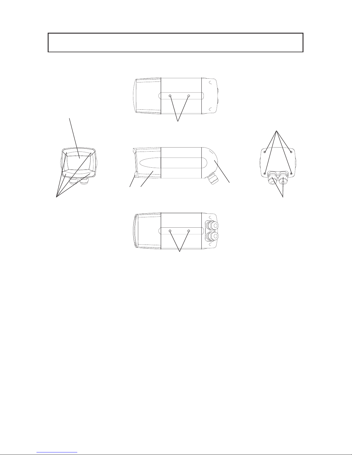
● Main unit
1.
PART NAMES AND FUNCTIONS
q Front glass
w Front cover fixing screw (4 pcs)
Concealed behind the ornamental cover.
To adjust the lens, these screws are loosened and the front cover is removed (P. 12).
e Tripod mounting thread (1/4-20UNC)
These threads are used to lock the Camera on a tripod or the mounting bracket
or mount a sun shade (P. 10).
The tripod mounting threads are provided at 2 locations (top and bottom) with
the depth of 7mm each.
r Ornamental cover
t Front cover
y Rear cover
u Rear cover fixing screw (4 pcs)
To connect the power cable, etc., theses screws are loosened and the rear
cover is removed (P. 9).
i
Waterproof cap
Unit: mm
q
e
e
i
r t
y
u
w
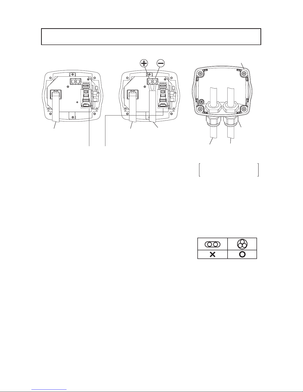
Page 9

- 8 -
o Monitor output
This is an image output terminal. When the shooting direction, the field angle or
the focus is adjusted, this terminal is connected to a monitor and the adjustment
is made while watching the monitor screen.
!0 Power input terminal (DC12V)
This is a terminal for fixing the power cable.
!1 Ethernet terminal (PoE)
This is an RJ-45 connector for Ethernet.
!2 DIP switch
This switch can initialize the settings (P. 16).
!3 Camera output
!4 Power input (DC12V )
!5 Sound input/output
!6 Alarm input/output
Note: The terminals !3 through !6 are used for connecting the multi-cable
SNC2230-03 (option).
For details, refer to the instruction manual of the multi-cable.
!1
!0
!2
!3
!4
!5
!6
o
Page 10
- 9 -
2.
CONNECTING THE CAMERA
1. Remove the rear cover.
2. Connect the power cable / the Ethernet cable.
Note: Select each cable according to the operating environment of this
Camera.
If waterproofing property is required, do not use any flat-wire type
cable since it is not adaptable to the waterproof cap.
When connecting, firmly fasten the
waterproof cap and confirm that the cable
has been fixed completely.
Be aware that if the cable is not fixed completely, water leak could be
caused. (Target tightening torque: 4.0 – 4.5N.m (35.4-39.8 lb.in))
Note: Do not use “Connector Cover (Modular Cover)” of RJ45 when
connecting “Ethernet cable” to SN2230 IP.
3.
Take out the attached silica gel from the outer bag, and stick it to the inside of the rear cover.
4. Mount the rear cover.
Note: The rear cover has a cushion for waterproofing. Confirm that the
cushion is set in the rear cover groove completely, and then mount
the rear cover. Be aware that if the cushion is not set in the rear
cover groove completely, water leak could be caused.
When mounting the rear cover, be careful not to pinch the dropping
preventive cord.
When using PoE When using DC12V
Ethernet cable
(To the PoE feeder)
To be used for connecting the multi-cable.
For details, refer to the instruction manual
of the multi-cable.
Cushion
Waterproof
cap
Power cable
(DC12V)
Applicable cable
diameter: 5.0 - 10.0mm
Ethernet cable
(To the network)
Power cable
or multi-cable
Ethernet cable
Page 11

- 10 -
[1] Sun shade (Cover for outdoor use)
3.
INSTALLATION PROCEDURES
How to install the sun shade
By using the metal fitting mounting holes
in the top of the Camera and the attached
mounting bolts (medium: 2 pcs), firmly
mount the sun shade (cover for outdoor use).
For the information of how to prepare the
mounting bolt, refer to the below figure.
Mounting bolt
Hole for bolt
Sun shade
Metal fitting
mounting hole
Camera main unit
Wall mounting
bracket
Camera front
Sun shade
Mounting bolt main body
Spring washer
Plain washer
Insulating spacer
Mounting bolt
[2] Fitting metals
Note: When installing the Camera
in a place where the Camera
is exposed to the direct sunlight,
be sure to mount the sun shade.
Mounting on the wall mounting bracket
(Outdoor specifications)
By using the metal fitting mounting holes
in the bottom of the Camera and the
attached mounting bolts (small: 2 pcs), fix
the Camera to the wall mounting bracket.
For the information of how to prepare the
mounting bolt, refer to the below figure.
Note: When the Camera is installed
outdoors, do not turn up the
Camera front above the level,
or the waterproofing property
will degrade.
Do not position the Camera upside
down.Firmly fasten the mounting
bolt not to be loosened, or the
Camera could drop.
Page 12

- 11 -
Camera front
Sun shade
Camera front
Mounting on the ceiling
mounting bracket
Mounting on the ceiling mounting bracket
(under-the-eaves and indoor specifications)
By using the metal fitting mounting holes
in the top of the Camera and the attached
mounting bolts (small: 2 pcs), fix the
Camera to the ceiling mounting bracket.
mounting bolt, refer to the below figure.
For the information of how to prepare the
mounting bolt, refer to P. 10 [1] Sun shade
(Cover for outdoor use).
Note: When the Camera is installed
outdoors, do not turn up the
Camera front above the level,
or the waterproofing property
will degrade.
Do not position the Camera upside
down.Firmly fasten the mounting
bolt not to be loosened,or the
Camera could drop.
Mounting on the ceiling mounting bracket
together with the sun shade
By using the metal fitting mounting holes
in the top of the Camera and the attached
mounting bolts (large: 2 pcs), fix the
Camera to the ceiling mounting bracket
For the information of how to prepare the
mounting bolt, refer to P. 10 [1] Sun shade
(Cover for outdoor use).
Note: When the Camera is installed
outdoors, do not turn up the
Camera front above the level,
or the waterproofing property
will degrade.
Do not position the Camera upside
down.Firmly fasten the mounting
bolt not to be loosened, or the
Camera could drop.
Mounting on the ceiling
mounting bracket
Page 13
- 12 -
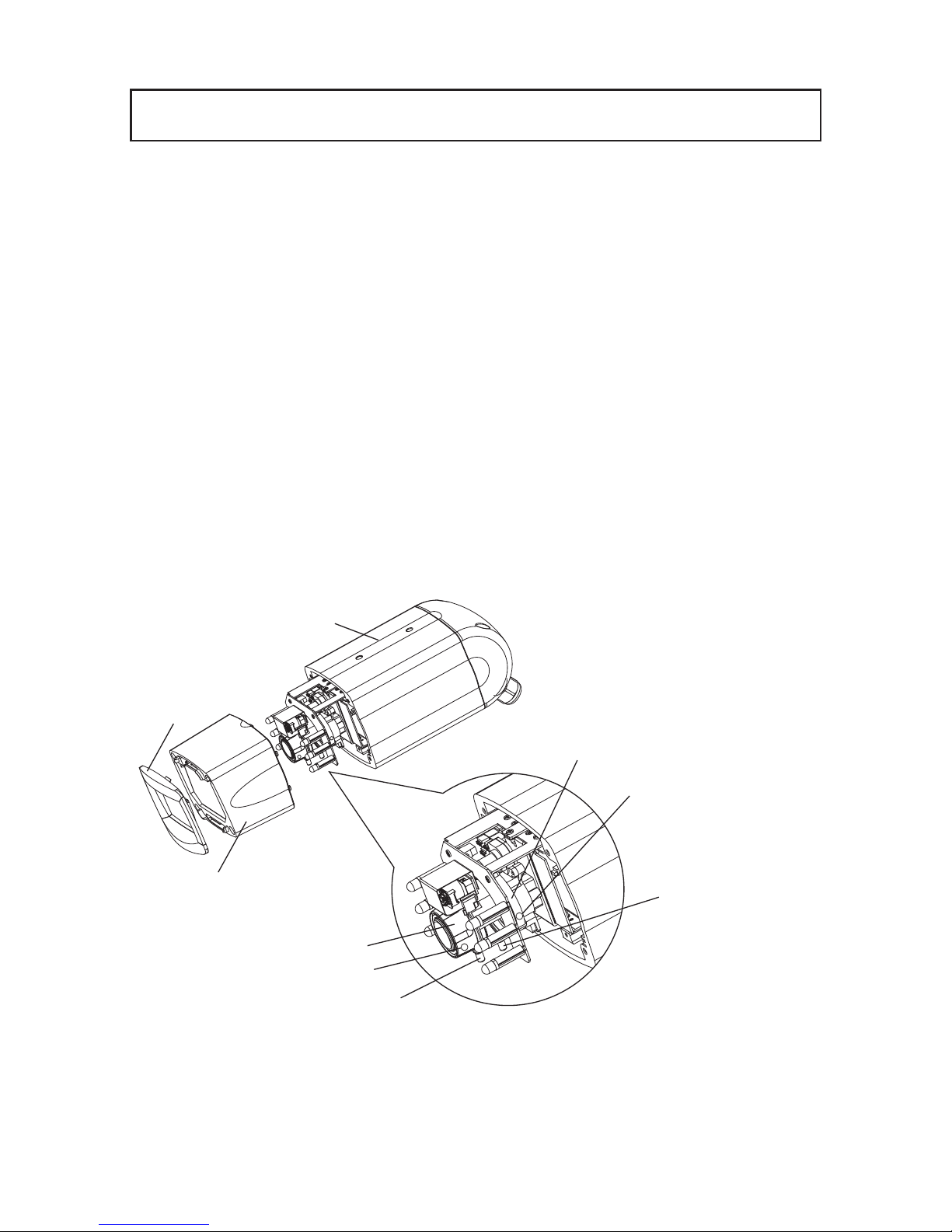
4.
LENS
Zoom ring
Focus ring
Focus locking knob
Camera main unit
Ornamental
cover
Front cover
Focus ring knob
Zoom ring knob
[1] Built-in lens
This Camera has a built-in dedicated vari-focal lens.
F: 0.95 – 1.8 f: 2.9 – 8.0mm
[2] Lens adjustment
Remove the ornamental cover and then the front cover to adjust the lens. Remove the
ornamental cover by pulling it to your side, and remove the front cover by loosen the
screws with a screwdriver. Now, the lens is ready for adjustment.
In adjusting the lens, loosen the zoom locking knob and adjust the lens field angle with
the zoom ring knob, and loosen the focus locking knob and adjust the focus with the
focus ring knob.
After the adjustment, firmly lock the zoom and the focus with the zoom ring locking
knob and the focus ring locking knob, respectively. (Factory settings: WIDE end,
infinity)
Zoom ring
locking knob
Page 14

- 13 -
After adjusting the lens, mount the front cover and then the ornamental cover. Mount the
front cover by fastening the screws with a screwdriver, and mount the ornamental cover
by pressing it to the front cover.
Note: The front cover has a cushion for waterproofing. Confirm that the
cushion is set in the front cover groove completely, and then mount
the front cover. Be aware that if the cushion is not set in the front
cover groove completely, water leak could be caused.
When mounting the front cover, be careful not to pinch the dropping
preventive cord.
Shift the dropping preventive cord to the main unit side to prevent the
cord from blocking the image, and then mount the front cover.
Page 15

- 14 -
5. Alarm
The alarm operation is enabled only when the multi-cable is in connection.
(For the details of connection, refer to the instruction manual of the multi-cable.)
Alarms are caused by “alarm 1”, “alarm 2”, and “motion detection”.
You can set an alarm action for each cause. “With/Without alarm”, “Send e-mail/Send
FTP/Both/None” are available.
Note: An alarm remains output from the alarm output terminal for ten
seconds. The alarm output period is fixed.
Specifications of the alarm output terminal: Open collector output,
maximum rating: DC12 V, 30 mA
Note: The next alarm input can work normally three seconds after the
current alarm is input. If the alarm input is active again within three
seconds, the alarm input may not work normally depending on the
equipment status.
Connected
to
network
None
Alarm input 1
(non-voltage make contact input)
Motion detected
Code
Signal name
color
Brown Alarm input 1
Red GND
Alarm input 2
(non-voltage make contact input)
Code
Signal name
color
Orange Alarm input 2
Yellow GND
Alarm output
(open collector output)
Code
Signal name
color
Green Alarm output
Camera
Multi-cable
Ethernet cable
Alarm
IN-OUT terminal
Input
Output
Send e-mail
(See page 35, 36
for setting)
Send FTP
(See page 37, 38
for setting)
Both
(See page 35, 36,
37 and 38 for setting)
Page 16

- 15 -
The sound input/output is enabled only when the multi-cable is in connection.
(For the details of connection, refer to the instruction manual of the multi-cable.)
Sound of the microphone connected to the Camera can be output from the speaker
connected to a client (PC, etc.) on the network, and sound of the microphone connected to a
client can be output from the speaker with amplifier connected to the Camera. For further
information about operation, see “Speaker” on page 26 and “(4) Sound” on page 51.
Note: When the dedicated software, “ELMO 1Channel Viewer”, is used for
the connection between a client and the Camera, no sound will be
transmitted or received if you select [MPEG4 Setting] – [Frame Rate]
(page 30 or 53) and set “1” or “5” at “Frame Rate”.
Note: When a Web browser is used for connecting a client to the Camera,
sound will not be transmitted from the Camera to the client.
Note: Sound can not be played on the PC if a sound card is not installed.
6. SOUND
Microphone
(Blue)
From client to Camera
From Camera to client
Camera
Connected to network
(Green)
Speaker with amplifier
Microphone
Speaker
Client
(PC,etc.)
Ethernetcable
Multi-cable
Page 17

- 16 -
7. INITIALIZING THE SETTINGS
1. Remove the rear cover.
2. Set the switch 1 of the DIP switch S901 on the rear
board to “ON”.
3. Turn on the power, and wait for 10 seconds. (The
settings will be initialized.)
4. After the power is turned OFF, set the switch 1 of the
DIP switch S901 to “OFF”.
5. Mount the rear cover.
S901
Note: Be sure to take the step 4. Set the DIP switch to OFF after
initialization. If the power is turned ON with the switch kept ON, all
settings will be initialized each time and will not be saved.
Page 18

- 17 -
You can use the following functions of the Camera from the host (PC) on a network by
connecting it to the network via Ethernet (10BASE-T/100BASE-TX):
• Web server function.............. For displaying live images and snapshots and remote-
operating the Camera on a Web browser.
• MPEG4 server function ........ For displaying live images and snapshots and remote-
operating the Camera on dedicated client software (ELMO
1 Channel Viewer: hereinafter called “Viewer”).
• Sound server function........... For receiving sound on a Web browser. For receiving or
transmitting sound on a Viewer.
• Alarm function...................... For saving image files in the server and transmitting e-mail
by alarm input.
• IP filtering function .............. For restricting hosts permitted to access the Camera.
Note: The Camera is not connectable to some network systems.
Note: Some restrictions may be placed on the host in access to the
Camera via a Web browser or Viewer. For further information, see
“(1) Restrictions under [3] Web browser” on page 21 and “(1)
Restrictions under [4] MPEG Viewer software ELMO 1Channel
Viewer” on page 47.
[1] Preparations for connection
Before connecting the Camera to a network, an IP address and other settings relating to the
network must be made.
The Camera offers the following two ways to make network settings:
• Accessing the Camera from the host on the network via a Web browser
• Accessing the Camera from the host on the network via Viewer
8. OPERATION PROCEDURES
Page 19
- 18 -
● Preparations before connection
Before connection, determine an IP address and a subnet mask to be set in the Camera. For
the IP address and the subnet mask, contact the administrator of the network you intend to
use.
The network settings of the Camera made by the factory are as follows:
IP address: 192.168.1.10
Subnet mask: 255.255.255.0
Note: If the address of the network you are going to use is not 192.168.1.0
or there is a host on the network whose IP address is 192.168.1.10,
you cannot connect the Camera to the network and make settings. In
this case, it is necessary to configure a network of 192.168.1.0
comprising the Camera and a host for setting it. Prepare a host with
an IP address of 192.168.1.X (X: 1 to 254 except 10) and a subnet
mask of 255.255.255.0, and connect the Camera to it.
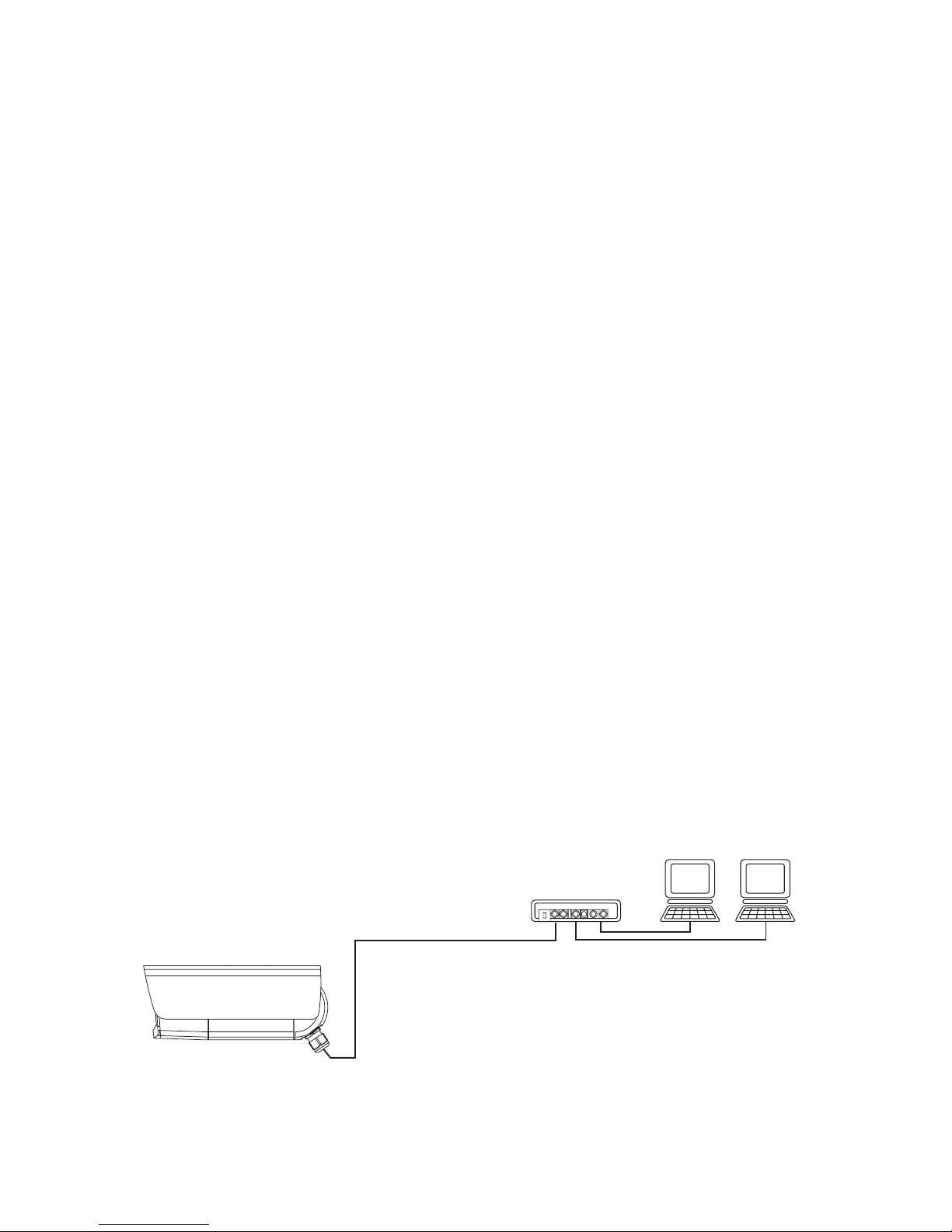
● Connection to the network
• Connection using a hub
Connect the Ethernet terminal (RJ-45) of the Camera and a port of the hub with each
other using an Ethernet straight cable (UTP category 5 or more) commercially available.
Do not use the MDI port of the hub.
When the PoE (Power over Ethernet) is used, a PoE load dispatching device (e.g., HUB)
is required.
Host
HUB
Ethernet straight cable
Host
.....
Page 20

- 19 -
• Connection to a host (For operation at DC12V)
Connect the Ethernet terminal (RJ-45) of the Camera and that of the host with each other
using the attached Ethernet cross cable or an Ethernet cross cable (UTP category 5 or
more) commercially available.
Note: As soon as a network unit is connected to its Ethernet terminal, the
Camera automatically adjusts and sets the 10BASE-T/100BASE-TX
and half-duplex/full-duplex communication conditions with the
connected unit (automatic negotiation).
The Camera does not always guarantee operation with all devices
compatible with automatic negotiation.
Ethernet cross cable
Host
Page 21
- 20 -
[2] Install
● Using a Web browser
Access to the Camera via a Web browser requires JRE1.5.0 (Sun Microsystems) or a
later version to have been installed and valid.
You can download Java Runtime Environment (JRE) from the company’s website. For
the installation of JRE, see the website.
● Using Viewer
Access to the Camera via Viewer requires DirectX 9.0C or a later version to have been
installed.
DirectX is contained in the Viewer install program on the CD-ROM. Install it according
to the instructions of the Viewer Install wizard.
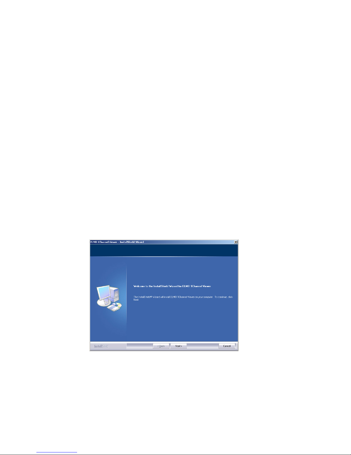
● Installing Viewer
Install Viewer by running the “ELMO 1Channel Viewer install program” on the attached
CD-ROM and opening Install Wizard.
As soon as the wizard begins to run, the following screen appears.
Install the program according to the instructions displayed on Wizard.
Upon completion of installation, an icon for “ELMO 1Channel Viewer” is displayed on
the desktop. You can start the Viewer software by clicking on this icon.
Page 22

- 21 -
● Uninstalling Viewer
Open “Add/Delete Software” (“Add/Delete Applications” for Windows2000) on “Control
Panel” then select “ELMO 1Channel Viewer” from the installed programs, and press the
[Change] button.
When the following screen is displayed, select “Remove” and press the [Next] button to
uninstall the ELMO 1Channel Viewer.
[3] Web browser
(1) Restrictions
Access to the Camera via a Web browser requires the PC to meet the following
requirements:
• Microsoft Windows 2000 or XP.
• JRE (Java Runtime Environment) 1.5.0 (Sun Microsystems) or a later version is
installed and valid.
• A browser is installed, which properly runs on Microsoft Windows 2000 or XP.
Note: The Camera does not ensure access via some Web browsers.
Note: Depending on the settings of Windows, anti-virus software or any
other software, the connection to the Camera may not be
established, the image may not be displayed or some other trouble
may occur.
Therefore, when setting Windows, anti-virus software and any other
software, comply with the instructions in their manuals to ensure the
appropriate settings.
Note: In the factory setting, the Camera uses the ports of TCP: 80, 3490 –
3495 and UDP: 3000 – 4000.
When connecting the Camera to a router, a firewall unit or any other
unit, set the ports of these units appropriately.
Page 23

- 22 -
(2) Connection
Start the Web browser on the host networked to the Camera.
Note: In the example of connection, Microsoft Internet Explorer is used.
1. Enter the IP address of the Camera in the URL input field on the Web browser.
1. Enter http:// at [Address].
2. When the IP address or host name of the Camera is assigned, enter the host name,
and put “/” at the end.
Example)
Since the IP address of the Camera set by the factory is 192.168.1.10,
enter http://192.168.1.10/.
2. Entry of the ID and password are requested.
When “User Authentication” is set to “Enable” on the Camera Control Setup, enter the
registered ID and password for login. In the factory setting, administrator ID and
password are both “root”.
When “User Authentication” is set to “Disable”, press the [OK] button with the login
ID and password left blank for login. Then, the login will be enabled by the operator
authority.
To log in by the administrator authority, enter the registered administrator ID and
password.
Page 24
- 23 -
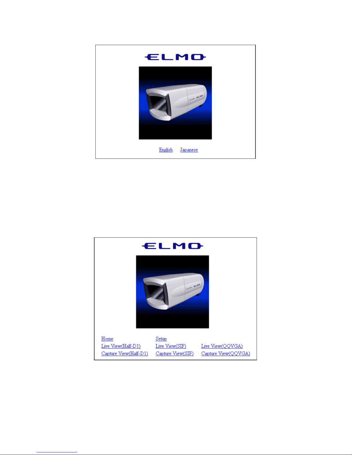
3. The page shown below is displayed on the Web browser.
4. Select English or Japanese.
Note: To display information in Japanese, the browser must be capable of
properly displaying Japanese pages.
5. The main page is displayed.
• Home .................................... Displays the main page.
• Setup ..................................... Displays the Setup screen.
• Live View (Half-D1) ............ Displays live images with a size of 704
× 480.
• Live View (SIF).................... Displays live images with a size of 352 × 240.
Page 25

- 24 -
• Live View (QQVGA) ........... Displays live images with a size of 160 × 120.
• Capture View (Half-D1)....... Displays capture images with a size of 704 × 480.
• Capture View (SIF) .............. Displays capture images with a size of 352 × 240.
• Capture View (QQVGA)...... Displays capture images with a size of 160 × 120.
6. For each function, see (3) to (19) that follow.
Page 26
- 25 -
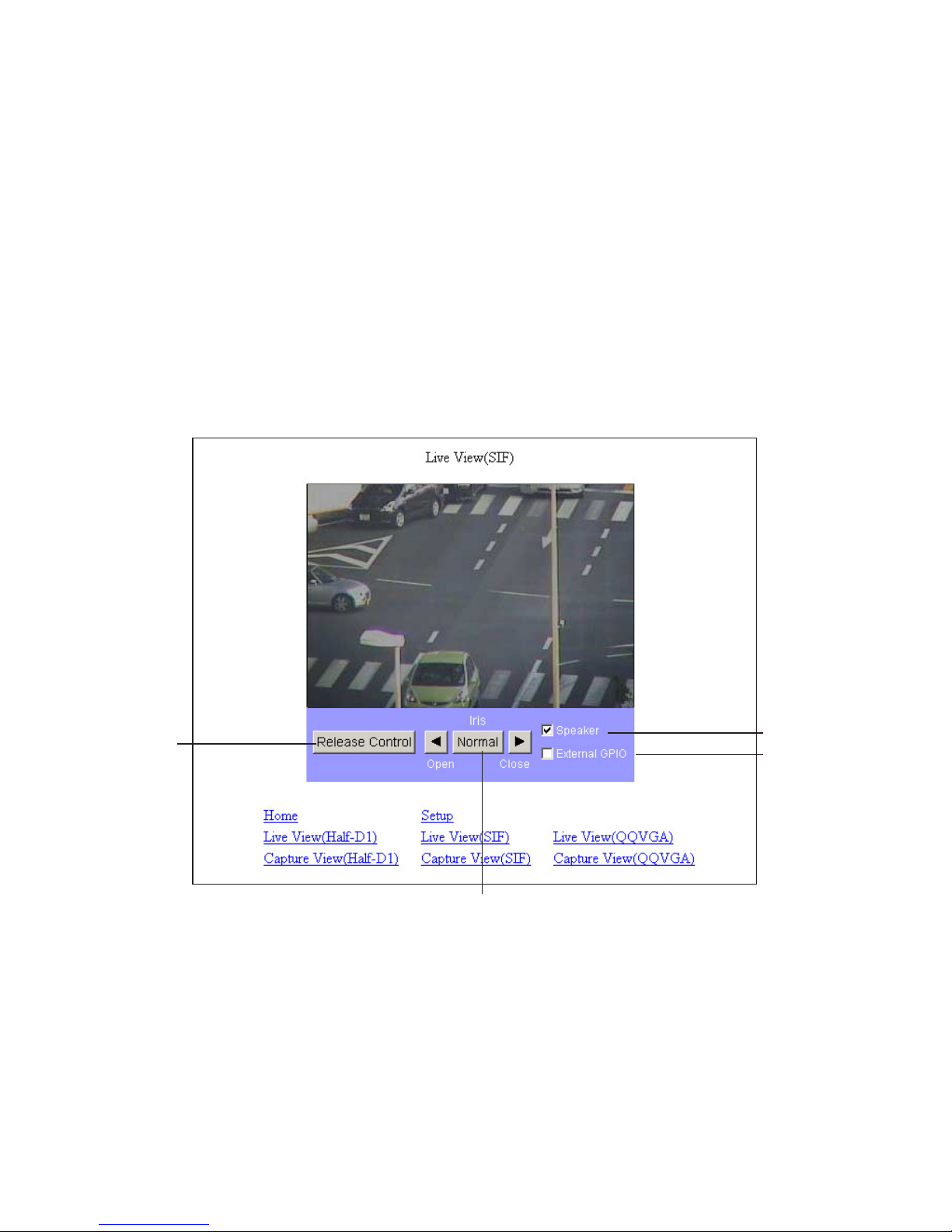
(3) Live display
Live images taken by the Camera are displayed.
On the main page, select the size of images you want to display live from [Live View (Half-
D1)], [Live View (SIF)], and [Live View (QQVGA)].
The sizes of live images are shown below.
• Half-D1 (704
× 480)
• SIF (352 × 240)
• QQVGA (160 × 120)
Note: Half-D1 displays 704 x 240 images in the size of 704 x 480.
Example) Live View (SIF) (352 × 240)
q Release Control .................. Releases the camera control policy. It is available when the
control policy is set to the Time Slice Share on the Camera
Control Setup screen (page 42). When there is no other
client to request the control policy, it is not released.
w
e
r
q
Page 27

- 26 -
w Iris ...................................... Adjusts the iris. The auto iris (the automatic adjustment
function to keep brightness at the same level even if the
state of the object changes) is valid at all times. Use the
“Open” and “Close” buttons to “increase” or “decrease”
brightness. By clicking on the “Normal” button, brightness
will be adjusted to the normal level.
Note: If [BLC MODE] is [WD] in P. 43 (17) and P. 67 (19) “Camera Settings
(AE Settings)”, this adjustment is disabled.
e Speaker............................... Set whether to output sound from the client when sound is
input through a microphone or another device connected.
r External GPIO................... Turns ON or OFF a external GPIO terminal.
Page 28

- 27 -
(4) Capture display
Snapshots can be obtained in the JPEG format.
On the main page, select the image size you want to obtain from [Capture View (Half-D1)],
[Capture View (SIF)], and [Capture View (QQVGA)].
The sizes of capture images are shown below.
• Half-D1 (704
× 480)
• SIF (352 × 240)
• QQVGA (160 × 120)
Note: Half-D1 displays 704 x 240 images in the size of 704 x 480.
Example) Capture View (SIF) (352 × 240)
• How to save snapshots
1. Click the right mouse button on the image.
2. Select “Save Image As” from the menu.
3. The image to be saved appears. Set a location for saving and a file name, and click
on the [Save] button.
Note: Half-D1 size images are saved in 704 x 240, meaning that they are
landscape. They can be viewed in the size of 704 x 480 on “Image
Viewer” that is installed together with “ELMO 1Channel Viewer”.
Note: The procedure described above may depend on the browser.
Page 29

- 28 -
(5) Settings
You can make all settings relating to the Camera.
You can jump to pages on which settings for the Camera can be made. To go to each setup
page, click on the corresponding link on the screen shown below.
Note: To change the settings, login by the administrator authority should
have been completed.
Note: Those characters available for setting each item are only the one-bite
alphanumeric characters and special characters (@, –, _, ¥, /, ', ", .).
The two-bite characters, including Japanese characters, are not
available.
Note: If the setting of any item is outlying or wrong, the equipment will not
operate normally. Be sure to set each item correctly within the
settable range.
Note: If the [Refresh] button of the browser is pressed on the Setup screen,
the Camera may not operate normally. In this case, redo the
connection.
Page 30

- 29 -
(6) External GPIO Setup
You can set the activation mode of the external GPIO.
• Activation Mode ................... Used to set the output mode of the external GPIO output
terminal.
The GPIO is controlled by the ON/OFF of the activation
mode and GPIO.
When the Camera is activated, the output is in the inactive
state (GPIO: OFF).
Normal Open...................... Close the contact during output to keep continuity.
Normal Close ..................... Open the contact during output.
Page 31

- 30 -
(7) MPEG4 Setup
Make settings for obtaining MPEG4 images.
Note: By changing this setting, the Camera itself may be reset and become
incapable of distributing images for a while.
• Bit Rate ................................. Designate the upper limit to the data amount to limit the
data amount generated during communication or image
distribution (setting range: 64 to 2000 kbps).
• Framerate .............................. Designate the number of frames to be displayed per second
(setting range: 30, 15, 10, 5, and 1 frames/second).
Note: When the frame rate is set to “1” or “5”, sound can not be transmitted
or received by using “ELMO 1Channel Viewer”.
• Resolution............................. Designate the size of images to be displayed.
D1: 704
× 480
SIF: 352 × 240
• Mode..................................... Set a delay for images according to the network
environment.
Frame ................................. Reduces the delay for images.
GOP.................................... Enables the Camera to deal with a poor-performance
network environment to some extent although the delay for
image is long.
Page 32

- 31 -
(8) JPEG Setup
Set image quality for JPEG images.
• JPEG Quality ........................ Designate image quality.
High.................................... High image quality. Although high-quality images can be
obtained, the load on the transmission line increases.
Normal ............................... Medium image quality with a compression rate between
High and Low.
Low .................................... Low image quality. The load on the transmission line
decreases.
Page 33

- 32 -
(9) Network Setup
Make settings relating to the network.
Note: Prior to making network settings, be sure to consult the network
administrator of the network to be used.
Note: If the setting of this item is changed, the connection setting of the
Camera may need to be changed. In this case, make the proper
connection setting and reconnect the Camera.
Note: If the same port number is redundant in port setting, the Camera will
not operate normally. Set different port number for each port.
Page 34

- 33 -
• Send Type ............................. Select a mode of distributing MPEG4 images.
UDP Unicast...................... UDP Unicast image data is distributed at the request of the
host for connection. Up to 3 addresses can be connected
from Viewer to the Camera.
Multicast ............................ UDP image data is distributed, irrespective of whether the
Camera is connected or is not connected from the host,
resulting in a decrease in the load on the Camera and the
transmission line. Although any number of addresses can
be set, image data may not be distributed properly
depending on the network environment.
TCP Unicast....................... TCP Unicast image data is distributed at the request of the
host for connection. Up to 3 addresses can be connected
from Viewer to the Camera.
• IP........................................... Set the IP address of the Camera.
• Gateway ................................ Designate the IP address of a router when it is used to
connect the Camera to an external network.
• DNS1/DNS2 ......................... Set the address of a DNS server to which the Camera is to
be connected. At DNS2, set the address of the DNS server
to which the Camera will be connected if it cannot connect
to DNS1.
• Net mask ............................... Set the subnet mask address of the Camera.
• Broadcast ............................. Set the broadcast address of the Camera.
• MAC Address ....................... Displays the MAC address of the Camera.
• Start Port Range.................... Designate the first of the ports the Camera opens to the
network (1024 to 65535).
• End Port Range..................... Designate the last of the ports the Camera opens to the
network (1024 to 65535).
• HTTP Port............................. Designate the port to be used for the Web server for the
Camera (80, 1024 to 65535).
• Option Port ........................... Designate the port to be used for distributing images from
the Camera (1024 to 65535).
• Multicast Port ....................... Designate the port to be used when the Camera is in
multicast mode (1024 to 65535).
Page 35

- 34 -
(10) Alarm Setup
Make settings relating to alarms.
• Alarm 1 / 2 / Motion Detection Title
.............................. Set any desired title of Alarm 1/2 or motion detection
(with up to 32 characters).
Note: Two-byte characters, including Japanese characters, are not
available for a title. Use one-byte alphanumerical characters.
Note: The alarm title will be displayed on the Viewer in about one second.
• Alarm 1 / 2 / Motion Detection Action
.............................. Select the action of the alarm when an alarm signal is input
to the alarm input terminal.
None................................... No action will take place.
Send FTP............................ The JPEG file of the obtained snapshot will be transferred
by FTP.
Send E-Mail ....................... E-mail will be transmitted.
Both.................................... The JPEG file of the obtained snapshot will be transferred
by FTP and e-mail will be transmitted at the same time.
Page 36

- 35 -
• Alarm 1 / 2 / Motion Detection Matched Resolution
............................... Designate the size of JPEG images to be attached when
transferring the FTP or transmitting e-mail as set at Alarm
1/2 Action.
Half-D1: 704
× 240 SIF: 352 × 240 QQVGA: 160 × 120
• Alarm 1/2 Out....................... Set whether to output an alarm when an alarm signal is
input to alarm input 1 or 2.
•
Motion Detection Alarm Out
....Set whether to give alarm output when a motion is detected.
(11) E-mail Setup
Make settings relating to e-mail.
• To.......................................... Designate the address to which e-mail will be transmitted
(with up to 64 characters).
• From...................................... Designate the e-mail address of the Camera (with up to 64
characters).
• CC1 to CC3 .......................... Designate an address to which e-mail will be transmitted at
the same time when it is sent to the e-mail address set at
To (with up to 64 characters).
• SMTP Address...................... Designate the SMTP server to be used (with up to 32
characters).
Page 37

- 36 -
• POP Address......................... Designate the POP server to be used (with up to 32
characters).
• Use Authentication ............... Designate whether to use user authentication on the SMTP
server to be used.
• Use POP Before SMTP ........ Designate whether to use POP before SMTP on the SMTP
server to be used.
• User ID ................................. Set a login ID for logging in to the SMTP server (with up
to 16 characters).
• User PW................................ Set a password for logging in to the SMTP server (with up
to 16 characters).
• Message ................................ Set a character string to be sent as a message when
transmitting e-mail (with up to 64 characters).
Note: Two-byte characters, including Japanese characters, are not
available for a message. Use one-byte alphanumerical characters.
• Action ................................... Select what to be sent when transmitting e-mail.
Text Only ........................... Only a character string will be sent when e-mail is
transmitted.
Picture Only ....................... Only an image will be sent when e-mail is transmitted.
Both.................................... Both a character string and an image will be sent when e-
mail is transmitted.
Page 38

- 37 -
(12) FTP Setup
Make settings relating to FTP connection.
• IP........................................... Designate the IP address of the server to which the FTP
will be transmitted.
• Port........................................ Designate the port number of the FTP server to which the
FTP will be transmitted. It is not generally necessary to
change the setting (21, 1024 to 65535).
• User ID ................................. Designate an account name for connection to the server to
which the FTP will be transmitted (with up to 16
characters).
• User PW................................ Designate a password for the account name shown above
(with up to 16 characters).
• Directory............................... Designate a directory for saving an image file, or a
directory with a write authority for the designated account
name (with up to 32 characters).
• Passive Mode........................ Designate whether to use passive mode or active mode for
transmitted the FTP. Use passive mode when there are
restrictions on the ports because of a firewall, etc.
Page 39

- 38 -
•Time Store ............................. Set whether to regularly transmit and save images in the
FTP server.
• Time Store login each send .. Set whether to connect to the FTP server each time images
are transmitted or not (always connected).
• Time Store dwell time .......... Set the interval at which images will be saved when Time
Store is valid (30 to 180 seconds).
• Time Store resolution ........... Designate the size of images to be saved.
Half-D1: 704
× 240
SIF: 352 × 240
QQVGA: 160 × 120
• Time Store filename ............. Designate a file name for the file to be saved. A file name
consists of the “entered file name” and “time”. The
extension “.jpg” will be added automatically to each file
name. If a file with the same name already exists in the
directory for saving, the data of the older file will be
overwritten. Designate a different file name (with up to 32
characters).
Note: Two-byte characters, including Japanese characters, are not
available for a file name to be saved. Use one-byte alphanumerical
characters.
Note: If any of such characters as “¥”, “/”, “.” is used for the Time Store file
name, the Camera may not operate normally depending on the
environment of the destination FTP server.
Page 40

- 39 -
(13) User Setup
Make settings relating to user administration.
• Adding a new user
You can register a login ID, a password, and authority for connection to the Camera.
Designate an authority, enter a login ID and a password, and then click on the [Add]
button. The entered data will be displayed in the list.
The following three items can be registered.
• Administrator................... The administrator authority. The login ID is fixed to
“root”. With this ID, you can view images, operate the
Camera, and make settings.
• Operator ........................... You can view images and operate the Camera.
• User.................................. You can only view images.
* Only “root” can be registered for Administrator, and up to 99 names can be registered
for Operator and User combined. You can use up to 16 one-byte characters for a
name, including alphanumerical characters and upper-case and lower-case alphabetic
characters.
Note: Two-byte characters, including Japanese characters, are not
available for a login ID and pass word. Use one-byte alphanumerical
characters.
Page 41

- 40 -
• Modifying a user
You can modify the registered login ID, password, and authority of any user for
connection to the Camera.
Select the user you want to modify from the list.
Designate the authority, enter the login ID and password, and press the [Modify] button.
Note: With regard to “root”, only the password can be changed.
• Deleting a user
You can delete the registered login ID, password, and authority of any user for
connection to the Camera.
Select the user you want to delete from the list, and click on the [Remove] button.
Note: You can not delete “root”.
Note: When “User Authentication” in “Camera Control Setup” is set to
“Disable”, only the password of the administrator authority can be
changed.
Page 42

- 41 -
(14) IP filtering Setup
Make settings relating to the IP filter.
Note: Making the settings described here may prevent connection to the
Camera. Perform the setting operation with extreme care.
Note: “Start IP” cannot be set larger than “End IP”.
• Enable IP Filter..................... Select whether to use the IP filter function.
• Accept all.............................. Accepts any client connected to the Camera, except
connections from the IP addresses shown in Exception
List. (Only connections from the IP addresses contained in
the client list will be rejected.)
• Reject all ............................... Rejects all clients attempting to connect to the Camera. It
can be connected from the IP addresses shown in
Exception List. (Only connections from the IP addresses in
Exception List will be permitted.)
• Adding an address
You can add addresses between the start and end addresses to the list.
Enter an address at each of “Start IP” and “End IP”, and click on the [Add] button.
Note: Up to 100 addresses can be registered.
• Modifying an address
Select the address you want to modify from the list.
Change the “start address” and the “end address”, and click on the [Modify] button. The
data will be corrected.
• Deleting an address
Select the address you want to delete from the list, and click on the [Remove] button.
Page 43

- 42 -
(15) Camera Control Setup
Make settings relating to the Camera.
• User Authentication.............. When the connection is made to the Camera, select
whether the user authentication should be “Enable” or
“Disable”. When “Disable” is selected, press the [OK]
button with the login ID and password left blank on the
Authentication screen displayed upon the connection.
Then, the login is enabled by the operator authority. To log
in by the administrator authority, enter the registered login
ID and password.
• Control Policy....................... Designate the mode of controlling the Camera.
All-Time Share................... Constantly accepts operations from all clients.
Time Slice Share ................ The operation authority will be released as soon as the
time set at “Control Duration Time” passes away, and will
be assigned to anther connecting client. It will remain
when there is no other connecting client.
Note: When the control is set as “Time Slice Share” in “Control Policy”, it
may occur temporarily that all connectors are in the state with no
control. Since this is a phenomenon due to the state of transmission,
the normal status can be resumed in seconds to minutes.
• Control Duration Time ......... Designate the period during which a client maintains
control when “Time Slice Share” is selected at “Control
Policy” (setting range: 1 to 60 minutes).
Page 44

- 43 -
(16) Camera Settings
(17) Camera Settings (AE Settings)
P.43
P.45
Page 45

- 44 -
To set the backlight compensation function to [ON/OFF].
When there is an intensive light in the background, this function
prevents the object from becoming dark.
BLC
To adjust the wide dynamic effect when [WD] is selected. Selection
can be made from among 3 levels of [LOW/MIDDLE/HI].
WD LEVEL
To select the Backlight Compensation Setting mode [AREA/HIST].
NOTE: When [WD] is changed to [HIST] or [AREA], [E-ZOOM] and
[IRIS] are returned tp the normal sate.
BLC MODE
AREA
About the Backlight Compensation Setting mode
To select the image area of the object that needs an appropriate
brightness and weighing according to the selected area.
HIST
WD
To make the dark (blackened) part of the image visible regardless of
the area.
To make the entire screen visible clearly.
Name Function
To set the low-speed shutter (electronic sensitivity up) to [ON/OFF].
When the object becomes dark, this function automatically varies the
CCD accumulated time across several fields up to the set maximum
level to optimize the brightness of the object.
LS-SHUTTER
To set the DAY/NIGHT function (IR cut filter removable function).
When this function is set to [AUTO], the filter is attached/removed
automatically according to the brightness. When the IR cut filter is
removed, the color image is switched to B&W image.
ICR
To set the maximum number of fields of the low-speed shutter [2fields,
3fields, 4fields, 5fields, 6fields, 8fields, 12fields, 20fields, 40fields,
80fields].
If the CCD
accumulated
time is set longer, the image frame rate will
decrease, and moving object could not be seen well.
LS-MAX
Page 46

- 45 -
To select the area [0 – 4] on the image where the backlight
compensation function works when [AREA] is selected.
AREA
AREA0
AREA4 AREA2AREA3
AREA1
Name Function
To set the maximum gain of the AGC [0dB, 4dB, 8dB,12dB,16dB,
20dB, 24dB].
The AGC is a function of amplifying the signal from the CCD to make
the object visible when the object becomes dark.
NOTE: When [ICR] is [AUTO], [AGC GAIN] can be set only to a
range of [12 – 24dB].
AGC GAIN
To set the infrared illumination to [OFF/ON].
LED
To set the high-speed shutter to [OFF/ON].
When the shutter is set to [OFF], the shutter speed is [1/60s].
When [HS-SHUTTER] is [ON], the shutter speed can be selected
from among [1/100s, 1/250s, 1/500s, 1/1000s, 1/2000s, 1/4000s,
1/10000s, 1/20000s, 1/50000s].
NOTE: When [LS-SHUTTER] is [ON] or [BLC MODE] is [WD], the
shutter speed can be set only to [1/100s].
HS-SHUTTER
To select the detail compensation level [-5 +10]
AP GAIN
Name Function
E-ZOOM
To set the maximum magnification [OFF, 1.1×, 1.2×, 1.4×, 1.6×, 1.8×,
2.0×, 2.2×, 2.4×, 2.5×]
NOTE : When [MLC MODE] is [WD], this setting is disabled.
(18) Camera Settings (Picture Settings)
Page 47

- 46 -
Name Function
To select the White Balance Setting mode [ATW, AWC, INDOOR,
OUTDOOR, FL-LIGHT, MWB].
WB
To adjust the white balance by way of continuous, automatic
following.
(When the image is in a single color all over, the white balance may
not be ajusted correctly.)
About the White Balance Setting mode
AT W
To adjust the white balance according to the then shooting status.
When the Setting mode is changed to [AWC] from the modes other,
be sure to set [TRIGGER] to ON.
AWC
This function is selected to shoot indoors.
The color temperature is assumed to be 3200K.
INDOOR
This function is selected to shoot outdoors.
The color temperature is assumed to be 6300K.
OUTDOOR
This function is selected when the Camera is used under the
fluorescent illumination. The color temperature is assumed to be
4200K.
FLLIGHT
To change the color tendency as desired.
MWB
To set the red color tendency [-30 +30] when [MWB] is selected.
MWB-R
To set the blue color tendency [-30 +30] when [MWB] is selected.
MWB-B
When [AWC] is selected and [TRIGGER] is set to “ON”, the white
balance is adjusted according to the current shooting status, by
selecting the [OK] button.
TRIGGER
(19) System Time Setup
Set the built-in clock of the Camera. The time of this clock will be added to the file name
when sending an E-mail or FTP.
Note: The built-in clock of the Camera can be set until December 31, 2036.
To operate each function of the Camera normally, use this system
time within the settable range.
Page 48

- 47 -
[4] MPEG4 Viewer software [ELMO 1Channel Viewer]
(1) Restrictions
Access to the Camera through “ELMO 1Channel Viewer” (hereinafter referred to as
“Viewer”) needs your computer to meet the following operating requirements:
• Microsoft Windows 2000 or XP.
• DirectX 9.0C or a later version is installed.
Note: The camera does not always ensure the proper operation of Viewer
in all environments.
Note: Depending on the settings of Windows, anti-virus software or any
other software, the connection to the Camera may not be
established, the image may not be displayed or some other troubles
may occur.
Therefore, when setting Windows, anti-virus software and any other
software, comply with the instructions in their manuals to ensure the
appropriate settings.
Note: In the factory setting, the Camera uses the ports of TCP: 80, 3490 –
3495 and UDP: 3000 – 4000.
When connecting the Camera to a router, a firewall unit or any other
unit, set the ports of these units appropriately.
(2) Connection
1. When running the Viewer program for the first time, Select Language window
appears to choose a language from “Japanese” or “English”.
Note: The language can also be changed after running the Viewer
program.
Page 49

- 48 -
2. Viewer’s main screen is displayed.
3. Select [Camera] – [Connect], and the Connect Dialog screen appears.
4. Enter the IP address, login name (ID), password, and connection port of the Camera you
want to connect, and click on the [OK] button. Viewer will be connected to the Camera,
and the screen will display an MPEG4 image and the Control Panel.
Page 50

- 49 -
(3) Live display
When double-clicking on the image, the image is enlarged to full screen. When double-
clicking again on the image, the image display returns to the original size.
• Obtaining snapshots
You can save snapshots, which are in sizes of Half-D1, SIF, and QQVGA, on the
Camera in a specific folder.
Select [Still] from the menu bar, or click on one of the [Half-D1], [SIF], and [QQVGA]
buttons on the tool bar.
The specific sizes of snapshots are shown below.
• Half-D1 (704
× 240)
• SIF (352 × 240)
• QQVGA (160 × 120)
Page 51

- 50 -
• Camera Control
• Iris
Open / Close....................... Adjusts the iris.
Normal ............................... Adjusts the brightness to the normal level.
* The auto iris (the automatic adjustment function to keep brightness at the same level
even if the state of the object changes) is valid at all times.
Note: If [BLC MODE] is [WD] in P. 43 (17) and P. 67 (19) “Camera Settings
(AE Settings)”, this adjustment is disabled.
• Release Ctrl........................... This function is available when Time Slice Share is set for
Control Policy in camera control setup (page 66) and
opens the control of the Camera. It does not open control
when there is no client requesting it.
Page 52

- 51 -
(4) Sound
Note: When using the Viewer and [MPEG4 Setup] – [Frame Rate] is
selected, the Frame rate must be set other than [1] · [5] for sound to
be transmitted.
• Receiving sound
Confirm that the speaker is connected properly to the host. When sound is input into the
Camera with the [Audio] – [Speaker] button in the Viewer menu or the icon on the
icon bar clicked on, the speaker connected to the host outputs it. No sound will be output
from the speaker connected to the host if the icon is not clicked on.
• Outputting sound
Confirm that the connection between the Camera and the loudspeaker with an amplifier
and the connection between the client and the microphone are proper. When sound is
input into the microphone connected to the client with [Audio] – [Microphone] button in
the Viewer menu or the icon on the icon bar clicked on, the loudspeaker with an
amplifier connected to the Camera outputs it. No sound will be output from the
loudspeaker with an amplifier connected to the Camera if the icon is not clicked on.
Note: The sound can be output only from Viewer to which login is made by
the administrator authority.
Page 53

- 52 -
(5) Settings
You can change the settings for the Camera.
Select [Setup] from the menu bar, and the setting menu shown below appears.
Note: To change the settings, login by the administrator authority should
have been completed.
Note: Those characters available for setting each item are only the one-bite
alphanumeric characters and special characters (@, –, _, ¥, /, ', ", .).
The two-bite characters, including Japanese characters, are not
available.
Note: If the setting of any item is outlying or wrong, the equipment will not
operate normally. Be sure to set each item correctly within the
settable range.
For further information about each setting, see (6) to (21) that follow.
Page 54

- 53 -
(6) MPEG4 Setup
Make settings for obtaining MPEG4 images.
Note: By changing this setting, the Camera itself may be reset and become
incapable of distributing images for a while.
• Quality .................................. Designate the upper limit to the data amount to limit the
data amount generated during communication or image
distribution (GOP: 64 to 2000 kbps, Frame: 500 to 2000
kbps).
• Frame Rate............................ Designate the number of frames to be displayed per second
(setting range: 30, 15, 10, 5, and 1 frames/second).
Note: Sound will not be received or transmitted if Frame rate is set to
[1], [5].
• Resolution............................. Designate the size of images to be displayed.
D1: 704
× 480
SIF: 352 × 240
• Mode..................................... Set a delay for images according to the network
environment.
Frame ................................. Reduces the delay for images.
GOP.................................... Enables the Camera to deal with a poor-performance
network environment to some extent although the delay for
image is long.
Page 55

- 54 -
(7) JPEG Setup
Set image quality for JPEG images.
• JPEG Quality ........................ Designate image quality.
High.................................... High image quality. Although high-quality images can be
obtained, the load on the transmission line increases.
Normal ............................... Medium image quality with a compression rate between
High and Low.
Low .................................... Low image quality. The load on the transmission line
decreases.
(8) Network Setup
Make settings relating to the network.
Note: Before making network settings, consult the administrator of the
network you are going to use.
Note: If this item is changed, the connection setting for the Camera may
need to be changed. In this case, make the proper connection
setting, and reconnect the Camera.
Note: If the same port number is redundant in port setting, the Camera will
not operate normally. Set different port number for each port.
Page 56

- 55 -
• Send Type ............................. Select a mode of distributing MPEG4 images.
UDP Unicast ...................... UDP Unicast Image data is distributed at the request of the
host for connection. Up to 3 addresses can be connected
from Viewer to the Camera.
Multicast ............................ UDP Image data is distributed, irrespective of whether the
Camera is connected or is not connected from the host,
resulting in a decrease in the load on the Camera and the
transmission line. Although any number of addresses can
be set, image data may not be distributed properly
depending on the network environment.
TCP Unicast ....................... TCP Unicast image data is distributed at the request of the
host for connection. Up to 3 addresses can be connected
from Viewer to the Camera.
• IP........................................... Set the IP address of the Camera.
• Broadcast .............................. Set the broadcast address of the Camera.
• Net mask ............................... Set the subnet mask of the Camera.
• Gateway ................................ Designate the IP address of a router when it is used to
connect the Camera to an external network.
• DNS1/DNS2 ......................... Set the address of a DNS server to which the Camera is to
be connected. At DNS2, set the address of the DNS server
to which the Camera will be connected if it cannot connect
to DNS1.
• MAC Address ....................... Displays the MAC address of the Camera.
• HTTP Port............................. Designate the port to be used for the Web server for the
Camera (80, 1024 to 65535).
• Option Port ........................... Designate the port to be used for distributing images from
the Camera (1024 to 65535).
• Multicast Port ....................... Designate the port to be used when the Camera is in
multicast mode (1024 to 65535).
• Audio Port............................. Designate the port to be used for transmitting and
receiving sound to/from the Camera (1024 to 65535).
• Start Port Range.................... Designate the first of the ports the client uses (1024 to
65535).
• End Port Range..................... Designate the last of the ports the client uses (1024 to
65535).
Page 57

- 56 -
(9) Alarm Setup
Make settings relating to alarms.
• Alarm 1 / 2 / Motion Detection Title
.............................. Set any desired title of alarm 1/ 2 or motion detection
(with up to 32 characters).
Note: Two-byte characters, including Japanese characters, are not
available for a title. Use one-byte alphanumerical characters.
Note: The alarm title will be displayed on the Viewer in about one second.
• Alarm 1 / 2 / Motion Detection Action
.............................. Select the action of the alarm when an alarm signal is input
to the alarm input terminal.
None................................... No action will take place.
Send FTP............................ The JPEG file of the obtained snapshot will be transferred
by FTP.
Send E-Mail ....................... E-mail will be transmitted.
• Alarm 1 / 2 / Motion Detection Matched Resolution
.............................. Designate the size of JPEG images to be attached when
transferring the FTP or transmitting e-mail as set at Alarm
1/2 Action or motion detection.
Half-D1: 704
× 240
SIF: 352 × 240
QQVGA: 160 × 120
Page 58

- 57 -
• Alarm 1/2 Output.................. Set whether to output an alarm when an alarm signal is
input to alarm input 1 or 2.
•
Motion Detection Alarm Out
.... Set whether to give alarm output when a motion is
detected.
(10) E-mail Setup
Make settings relating to e-mail.
• E-mail ................................... Designate the address to which e-mail will be transmitted
(with up to 64 characters).
• E-mail From.......................... Designate the e-mail address of the Camera (with up to 64
characters).
• E-mail CC1 to CC3............... Designate an address to which e-mail will be transmitted at
the same time when it is sent to the e-mail address set at
To (with up to 64 characters).
• E-mail Act............................. Select what to be sent when transmitting e-mail.
Text Only ........................... Only a text will be sent when e-mail is transmitted.
Picture Only ....................... Only an image will be sent when e-mail is transmitted.
Both.................................... Both a text and an image will be sent when e-mail is
transmitted.
• SMTP.................................... Designate the SMTP server to be used (with up to 32
characters).
• POP....................................... Designate the POP server to be used (with up to 32
characters).
• User ID ................................. Set a login ID for logging in to the SMTP server (with up
to 16 characters).
• User PW................................ Set a password for logging in to the SMTP server (with up
to 16 characters).
Page 59

- 58 -
• Message ................................ Set a text to be sent as a message when transmitting e-mail
(with up to 64 characters).
Note: Two-byte characters, including Japanese characters, are not
available for a Message. Use one-byte alphanumerical characters.
• Use Authentication ............... Designate whether to use user authentication on the SMTP
server to be used.
• Use POP before SMTP ......... Designate whether to use POP before SMTP on the SMTP
server to be used.
(11) FTP Setup
Make settings relating to connection.
• IP........................................... Designate the IP address of the server to which the FTP
will be transmitted.
• Port........................................ Designate the port number of the FTP server to which the
FTP will be transmitted. It is not generally necessary to
change the setting (21, 1024 to 65535).
• Directory............................... Designate a directory for saving an image file, or a
directory with a write authority for the designated account
name (with up to 32 characters).
• User ID ................................. Designate an account name for connection to the FTP
server to which the FTP will be transmitted (with up to 16
characters).
• User PW................................ Designate a password for the account name shown above
(with up to 16 characters).
Page 60

- 59 -
• Passive Mode........................ Designate whether to use passive mode or active mode for
transferring the FTP. Use passive mode when there are
restrictions on the ports because of a firewall, etc.
• Time Store Dwell Time ....... Set the interval at which images will be saved when Time
Store is valid (30 to 180 seconds).
• Time Store Resolution .......... Designate the size of images to be saved.
Half-D1: 704
× 240
SIF: 352 × 240
QQVGA: 160 × 120
• Time Store filename ............. Designate a file name for the file to be saved. A file name
consists of the “entered file name” and “time”. The
extension “jpg” will be added automatically to each file
name. If a file with the same name already exists in the
directory for saving, the data of the older file will be
overwritten. Designate a different file name (with up to 32
characters).
Note: Two-byte characters, including Japanese characters, are not
available for a file name to be saved. Use one-byte alphanumerical
characters.
Note: If any of such characters as “¥”, “/”, “.” is used for the file name, the
Camera may not operate normally depending on the environment of
the destination FTP server.
• Time Store Enable ............... Set whether to regularly save images in the FTP server.
• Login each send .................... Set whether to connect to the FTP server each time images
are transmitted or not (always connected).
Page 61

- 60 -
(12) Motion Detection Setup
• Use Motion Detection........... Set whether to perform motion detection.
• Sensitivity ............................. Set the sensitivity of motion detection.
• Area settings
When “Select” under “Tools” is checked, the area on the screen that is selected by drag
& drop will be set for a motion detection area. When “Delete” is checked, the set motion
detection area will be cancelled.
[Reset] button: Cancels all areas.
[Select All] button: Sets all areas.
[Reverse] button: Reverses a detection area to non-detection area and vice versa.
[Apply] button: Applies the settings made.
Page 62

- 61 -
(13) User Setup
Make settings relating to user administration.
• Adding a new user
You can register a login ID, a password, and authority for connection to the Camera.
Designate an authority, enter a login ID and a password, and then click on the [Add]
button. The entered data will be displayed in the list.
The following three items can be registered.
• Administrator................... The administrator authority. The login ID is “root” that is
unchangeable. With this ID, you can view images, operate
the Camera, and make settings.
• Operator ........................... You can view images and operate the Camera.
• User.................................. You can only view images.
* Only “root” can be registered for Administrator, and up to 99 names can be registered
for Operator and User combined. You can use up to 16 one-byte characters for a iogin
ID and password, including alphanumerical characters and upper-case and lower-case
alphabetic characters.
Note: Two-byte characters, including Japanese characters, are not
available for a login ID and password. Use one-byte alphanumerical
characters.
Page 63

- 62 -
• Modifying a user
You can modify the registered login ID, password, and authority of any user for
connection to the Camera.
Select the user you want to modify from the list.
Designate the authority, enter the login ID and password, and press the [Modify] button.
Note: For to “root”, only the password can be changed.
• Deleting a user
You can delete the registered login ID, password, and authority of any user for
connection to the Camera.
Select the user you want to delete from the list, and click on the [Remove] button.
Note: You cannot delete “root”.
Note: When “User Authentication” in “Camera Control Setup” is set to
“Disable”, only the password of the administrator authority can be
changed.
Page 64

- 63 -
(14) IP filtering Setup
Make settings relating to the IP filter.
Note: Making the settings described here may prevent connection to the
Camera. Perform the setting operation with extreme care.
Note: “Start IP” cannot be set larger than “End IP”.
• Enable IP Filtering................ Select whether to use the IP filter function.
• Accept All............................. Accepts any client connected to the Camera, except
connections from the IP addresses shown in Exception
List. (Only connections from the IP addresses contained in
the client list will be rejected.)
• Reject All.............................. Rejects all clients attempting to connect to the Camera. It
can be connected from the IP addresses shown in
Exception List. (Only connections from the IP addresses in
Exception List will be permitted.)
• Modifying an address
Select the address you want to modify from the list.
Change the address set at each of “Start IP” and “End IP”, and click on the [Modify]
button.
• Deleting an address
Select the address you want to delete from the list, and click on the [Remove] button.
Page 65

- 64 -
• Reset
The button sets all addresses registered in the list at “0.0.0.0”.
(15) Snapshot Setup
Make settings relating to snapshots on this screen.
• Path ....................................... Set a directory for saving snapshots. In snapshot saving,
the [MAC address] folder and [Date] folder of the Camera
connected to the set path folder are created, and snapshots
are saved there. These folders can be referred to by
pressing the [Browse] button.
• File name .............................. Designate the saving file name. The file name consists of
“Input file name” + “Time” + “Image size”. The file name
is attached with the .jpg extension.
• Enable Overwrite.................. Enables the overwrite of the last saved snapshot when
saving a new snapshot with the same file name.
Note: Depending on the OS in use, the file name length and the directory
name length are determined. Therefore, set the file name and the
directory name appropriately according to the OS in use.
Page 66

- 65 -
(16) Color Setup
Set the brightness, contrast, hue, and saturation of images on this screen.
• Brightness ............................. Sliding the control knob to the right makes the image
brighter.
• Contrast................................. Sliding the control knob to the right makes the contrast
stronger.
• Hue........................................ Sliding the control knob to the right and left changes the
hue.
• Saturation.............................. Sliding the control knob to the right makes the color
deeper.
Note: The color setup will not be reflected on the image to be output from
the image output terminal.
Page 67

- 66 -
(17) Camera Control Setup
Make settings relating to the Camera.
• Control Policy....................... Designate the mode of controlling the Camera.
All-Time Share................... The control policy remains unless the client having an
operation authority cuts off the connection.
Time Slice Share ................ The operation authority will be released as soon as the
time set at “Control Duration Time” passes away, and will
be assigned to anther connecting client. It will remain
when there is no other connecting client.
Note: When the control is set as “Time Slice Share” in “Control Policy”, it
may occur temporarily that all connectors are in the state with no
control. Since this is a phenomenon due to the state of transmission,
the normal status can be resumed in seconds to minutes.
• Control Duration Time ......... Designate the period during which a client maintains
control when “Time Slice Share” is selected at “Control
Policy” (setting range: 1 to 60 minutes).
• User Authentication.............. Select whether the login ID and the password should be
entered on the Authentication screen for a client to be
connect to the Camera. When “Disable” is selected, press
the [OK] button with the login ID and password left blank
for login on the Connection Setting screen. Then, the login
will be enabled by the operator authority. To log in by the
administrator authority, enter the registered administrator
ID and password.
Page 68

- 67 -
(18) External GPIO Setup
You can set the activation mode of the external GPIO.
• Activation Mode ................... Used to set the output mode of the external GPIO output
terminal.
The GPIO is controlled by the ON/OFF of the activation
mode and GPIO. When the Camera is activated, the output
is in the inactive state (GPIO: OFF).
Normal Open...................... Closes the contact during output to keep continuity.
Normal Close ..................... Opens the contact during output.
(19) Camera Settings (AE Settings)
For each setting item, see the description of each function on page 43.
Page 69

- 68 -
(20) Camera Settings (Picture Settings)
For each setting item, see the description of each function on page 44-45.
(21) System Time Setup
Set the internal clock of the Camera. The time of this clock will be added to the file name
when sending an E-mail or FTP.
Note: The internal clock of the Camera can be set until December 31,
2036.
The system clock must be set within this range or the camera will not
function normally.
Page 70

- 69 -
(22) Tools
Select [Tools] from the menu bar, and the Tool menu shown below appears.
• Display Motion Detection .... Displays an area in which some motion is detected on the
MPEG4 live image screen.
• External GPIO On ................ Turns ON or OFF output from the general-purpose output
terminal.
• Always Top........................... Displays Viewer on top of the other screens displayed at
all times even if it is not active.
• Full Display Mode ................ Displays the image in the entire window, irrespective of
the image’s aspect ratio.
• Import Setup Data................. Reads the setup file created in “Export Setup Data” and
sets the Camera. Press the [Browse] button and designate
the setup file to be read, and press the [Import Start] button
and import the settings (available only when the Camera is
connected).
• Export Setup Data................. Creates each setting values of the Camera in a setup file
and saves the setup file in the PC. Press the [Browse]
button and designate the setup file path, and press the
[Export Start] button and export the settings (available
only when the Camera is connected).
Note: “Import/Export Setup Data” must be executed on the cameras of the
same firmware version.
• Open Snapshot Folder .......... Opens the file designated at Path on the Snapshot Setup
screen.
Page 71

- 70 -
• Image Viewer ....................... Displays the JPEG images saved in the PC.
Displays the JPEG images in D1, which was acquired in
Half-D1.
• Language Setup .................... Set English or Japanese for Viewer (the selection becomes
valid after Viewer is turned OFF and ON again).
• Network Update.................... Rewrites the firmware for the Camera networked.
• Camera Control..................... Displays the camera control on the right side of the Main
screen of Viewer.
(23) Firmware update
You can update the firmware for the Camera (Camera operation programs) via a network
for the purpose of improving its functions.
Since an update changes the key functions of the Camera, it may fail to get started or
malfunction if the update is not carried out correctly.
Update the firmware according to the procedure described below with extreme care.
Do not attempt to modify the firmware for firmware updating that was distributed by the
shop where you purchased the product or our branch or sales office nearby. Using another
firmware or modified firmware may cause the Camera to malfunction.
1. Turn OFF the power to the Camera, and connect it and the host one-to-one with a
cross cable.
Page 72

- 71 -
2. Set the network for the host according to the network address of the Camera.
3. Turn ON the power to the Camera, and select [Tool] – [Network Update] from the
menu bar of Viewer on the host.
4. The Net Update window opens. Set correct data at each of IP (the Camera’s IP
address), Port (the Camera’s optional port number), ID (the Camera’s
administrator login name), and Password (the Camera’s login password).
5. Designate the program file for updating firmware distributed by the shop where
you purchased the product or our branch or sales office nearby, and the program
file for the Web.
6. Click on the [Start Update] button at the bottom of the screen.
7. The state shown on the line named [State] is updated, and “Complete” is displayed
after the update is properly completed. If “Error Connect” is displayed, the
connection or any of the network settings is incorrect. Reconfirm the connection
between the Camera and the host and the network settings.
8. After the firmware is updated properly, the Camera completes getting restarted
within several seconds and gets ready to be connected. Click on the [OK] button
to close the Firmware Update window.
9. Reset the Camera to the default factory settings by referring to P. 16
[7] Initializing the settings.
10. Redo the setting, and confirm the normal operation.
Page 73

- 72 -
[5] Set items
● AE Settings
Name Function
Factory settings
ICR To set the DAY/NIGHT function (IR cut filter removable OFF
function).When this function is set to [AUTO], the filter
is attached/removed automatically according to the
brightness. When the IR cut filter is removed, the color
image is switched to B&W image.
LS-SHUTTER
To set the low-speed shutter (electronic sensitivity up) OFF
to [ON/OFF]. When the object becomes dark, this
function automatically varies the CCD accumulated time
across several fields up to the set maximum level to
optimize the brightness of the object.
LS-MAX To set the maximum number of fields of the low-speed 4fields
shutter [2fields, 3fields, 4fields, 5fields, 6fields, 8fields,
12fields, 20fields, 40fields, 80fields].
If the CCD accumulated time is set longer, the image
frame rate will decrease, and moving object could not
be seen well.
BLC
To set the backlight compensation function to [ON/OFF].
OFF
When there is an intensive light in the background, this
function prevents the object from becoming dark.
BLC MODE
To select the Backlight Compensation Setting mode WD
[AREA/HIST].
NOTE: When [WD] is changed to [HIST] or [AREA],
[E-ZOOM] and [IRIS] are returned to the normal sate.
About the Backlight Compensation Setting mode
WD To make the entire screen visible clearly.
HIST To make the dark (blackened) part of the image visible
regardless of the area.
AREA To select the image area of the object that needs an
appropriate brightness and weighing according to the
selected area.
WD LEVEL To adjust the wide dynamic effect when [WD] is MIDDLE
selected. Selection can be made from among 3 levels
of [LOW/MIDDLE/HI].
Page 74

- 73 -
Name Function
Factory settings
AREA To select the area [0 〜 4] on the image where the 4
backlight compensation function works when [AREA] is
selected.
HS-SHUTTER
To set the high-speed shutter to [OFF/ON]. OFF
When the shutter is set to [OFF], the shutter speed is
[1/60s].
When [HS-SHUTTER] is [ON], the shutter speed can be
1/100s
selected from among [1/100s, 1/250s, 1/500s, 1/1000s,
1/2000s, 1/4000s, 1/10000s, 1/20000s, 1/50000s].
NOTE: When [LS-SHUTTER] is [ON] or [BLC MODE] is
[WD], the shutter speed can be set only to [1/100s].
AGC GAIN To set the maximum gain of the AGC [0dB, 4dB, 8dB, 8dB
12dB,16dB, 20dB, 24dB].
The AGC is a function of amplifying the signal from the
CCD to make the object visible when the object
becomes dark.
NOTE: When [ICR] is set to [AUTO], [AGC GAIN] can
be set only to a range of [12 – 24dB].
LED To set the infrared illumination to [OFF/ON]. OFF
Name Function
Factory settings
E-ZOOM
To set the maximum magnification [OFF, 1.1x, 1.2x, 1.4x,
OFF
1.6x, 1.8x, 2.0x, 2.2x, 2.4x, 2.5x]
NOTE : When [MLC MODE] is [WD], this setting is disabled.
AP GAIN To select the detail compensation level [-5 〜 10] ±0
WB To select the White Balance Setting mode [ATW, AWC, ATW
INDOOR, OUTDOOR, FL-LIGHT, MWB].
About the White Balance Setting mode
ATW To adjust the white balance by way of continuous,
automatic following.
(When the image is in a single color all over, the white
balance may not be ajusted correctly.)
AWC To adjust the white balance according to the then
shooting status. When the Setting mode is changed to
[AWC] from the modes other than [AWC], be sure to
set [TRIGGER] to ON.
● PICTURE Settings
AREA0
AREA3
AREA1
AREA2AREA4
Page 75

- 74 -
Name Function
Factory settings
ID The following three items can be set according to the root
user settings: (AdminiAdministrator: The administrator authority. The login strator)
ID is “root” that is unchangeable. With this login ID, you
can view images, operate the Camera, and make
settings.
Operator: You can view images and operate the
Camera.
User: You can only view images.
* Only “root” can be registered for Administrator, and
up to 99 names can be registered for Operator and
User combined.
* You can use up to 16 one-byte characters for a name,
including alphanumerical characters and upper-case
and lower-case alphabetic characters.
Password Set a password for the ID. root
* You can use up to 16 one-byte characters for a
password, including alphanumerical characters and
upper-case and lower-case alphabetic characters.
● Camera ID, password
Name Function
Factory settings
INDOOR
This function is selected to shoot indoors.
The color temperature is assumed to be 3200K.
OUTDOOR
This function is selected to shoot outdoors.
The color temperature is assumed to be 6300K.
FL-
This function is selected when the Camera is used
LIGHT
under the fluorescent illumination. The color temperature
is
assumed to be 4200K.
MWB To change the color tendency as desired.
TRIGGER
When [AWC] is selected and [TRIGGER] is set to “ON”, OFF
the white balance is adjusted according to the current
shooting status, by selecting the [OK] button.
MWB-R To set the red color tendency [-30
〜 +30] when [MWB] ±0
is selected.
MWB-B To set the blue color tendency [-30
〜 +30] when ±0
[MWB] is selected.
Page 76

- 75 -
● MPEG4
Make settings for MPEG4 display using “ELMO 1Channel Viewer”.
Name Function
Factory settings
Quality Designate the upper limit to the data amount to limit 2000(kbps)
the data amount generated during communication or
image distribution.
Frame: 500 - 2000 (kbps)
GOP:64 - 2000 (kbps)
Framerate Designate the number of frames to be displayed per 30(frames/
second. second)
(setting range: 30, 15, 10, 5, and 1 frames/second).
Resolution Designate the size of images to be displayed. D1
D1 (704 x 480) , SIF(352 x 240)
Mode Set a delay for images according to the network Frame
environment.
Frame: Reduces the delay for images.
GOP: Enables live images to be viewed even on a
poor-performance network although the delay for
images is long.
● JPEG
Make settings for motion JPEG display and capture display using a browser and for
snapshot acquisition using “ELMO 1Channel Viewer”.
Name Function
Factory settings
JPEG Designate image quality. Normal
Quality
High: High image quality.
Normal: Medium image quality with a compression
rate between High and Low.
Low: Low image quality.
● External GPIO
Name Function
Factory settings
Activation Set the output mode. Normal
Mode
Normal Open: High impedance is usually activated, Open
and the GND level becomes valid during output.
Normal Close: The GND level is usually activated,
and high impedance becomes valid during output.
Page 77

- 76 -
● Network
Consult the administrator of the network you intend to use before making network
settings.
Name Function
Factory settings
MPEG4 Select a MPEG4 distribution method. UDP
Send Type
UDP Unicast: A method of sending the UDP image Unicast
data by the connection request from the client.
Multicast: A method of sending the same UDP image
data to the multiple addresses in the same network.
TCP Unicast: A method of sending the TCP image
data by the connection request from the client.
IP address Set the IP address of the Camera. 192.168.1.
10
Gateway Designate the IP address of a router when it is used to 192.168.1.
connect the Camera to an external network. 1
DNS1 Set the address of a DNS server to which the Camera 0.0.0.0
is to be connected.
DNS2 Set the address of the DNS server to which the 0.0.0.0
Camera will be connected if it cannot connect to DNS1.
Subnet Set the subnet mask of the Camera. 255.255.
mask 255.0
Broadcast Set the broadcast address of the Camera. 192.168.1.
255
Start Port Designate the first of the ports the client uses. 3000
End Port Designate the last of the ports the client uses. 4000
HTTP Port Designate the port to be used for the Web server for 80
the Camera.
Option Port Designate the port to be used for distributing images 3491
from the Camera
Multicast Designate the port to be used when the Camera is in 3490
Port multicast mode.
Audio Port Designate the port to be used for transmitting and 3493
receiving sound to/from the Camera.
Page 78

- 77 -
● Alarm
Name Function
Factory settings
Alarm 1 Set any desired title of alarm 1. Event1
* Two-byte characters, including Japanese characters,
are not available for a title.
Use one-byte alphanumerical characters.
Alarm 1 Select the mode of the alarm to be effective when None
Action an alarm input signal (no-voltage make contact) is
input to alarm IN-OUT terminal “ALARM IN1 (brown)”.
None: No action will take place.
Send FTP: The JPEG file of the obtained snapshot
will be transmitted by FTP.
Send E-Mail: E-mail will be transmitted.
Both: The JPEG file of the obtained snapshot will be
transmitted by FTP and e-mail will be transmitted at the
same time.
Matched Designate the size of JPEG images to be attached SIF
Resolution when transmitting the FTP or transmitting e-mail as
(Alarm 1) set at Alarm 1 Action.
Half-D1/SIF/QQVGA
Alarm 2 Set any desired title of alarm 2. Event2
* Two-byte characters, including Japanese characters,
are not available for a title.
Use one-byte alphanumerical characters.
Alarm 2 Select the mode of the alarm to be effective when None
Action an alarm input signal (no-voltage make contact) is
input to alarm IN-OUT terminal “ALARM IN2 (orange)”.
None: No action will take place.
Send FTP: The JPEG file of the obtained snapshot
will be transferred by FTP.
Send E-Mail: E-mail will be transmitted.
Both: The JPEG file of the obtained snapshot will be
transferred by FTP and e-mail will be transmitted at the
same time.
Page 79

- 78 -
Name Function
Factory settings
Matched Designate the size of JPEG images to be attached SIF
Resolution when transmitting the FTP or transmitting e-mail as
(Alarm 2) set at Alarm 2 Action.
Half-D1/SIF/QQVGA
Motion Set any desired title of Motion Detection. Motion
Detection Two-byte characters, including Japanese characters, Detection
Title are not available for a title.
Use one-byte alphanumerical characters.
Motion Select an alarm action to take place when an action is None
Detection detected under the action detection settings made on
Action Viewer.
None: No action will take place.
Send FTP: The JPEG file of the obtained snapshot
will be transmitted by FTP.
Send E-Mail: E-mail will be transmitted.
Both: The JPEG file of the obtained snapshot will be
transmitted by FTP and e-mail will be transmitted at the
same time.
Matched Designate the size of JPEG images to be attached SIF
Resolution when transmitting the FTP or transmitting e-mail as
(Motion set at Motion Detection Action.
Detection) Half-D1/SIF/QQVGA
Alarm 1 An alarm output signal (open collector output) will None
Output be output to alarm IN-OUT terminal “ALARM OUT
(green)”
when alarm 1 is activated.
Alarm 2 An alarm output signal (open collector output) will None
Output be output to alarm IN-OUT terminal “ALARM OUT
(green)”
when alarm 2 is activated.
Motion An alarm output signal (open collector output) will None
Detection be output to alarm IN-OUT terminal “ALARM OUT
Alarm Out (green)”
when a motion is detected.
Page 80

- 79 -
● E-mail
Name Function
Factory settings
E-mail Designate the address to which e-mail will be None
transmitted.
E-mail from Designate the e-mail address of the Camera. None
E-mail CC1 Designate an address to which e-mail will be None
/ CC2 transmitted at the same time when it is sent to the
/ CC3 e-mail address set at To.
SMTP Designate the SMTP server to be used. None
POP Designate the POP server to be used. None
Use Designate whether to use user authentication on the None
Authentica- SMTP server to be used.
tion
POP before Designate whether to use POP before SMTP on the None
SMTP SMTP server to be used.
User ID Set a login ID for logging in to the SMTP server. None
User PW Set a password for logging in to the SMTP server. None
Message Set a text to be sent as a message when transmitting None
e-mail.
Action
Text Only: Only a text will be sent when e-mail is Both
transmitted.
Picture Only: Only an image will be sent when e-mail
is transmitted.
Both: Both a text and an image will be sent when
e-mailis transmitted.
Page 81

- 80 -
● FTP
Name Function
Factory settings
IP address Designate the IP address of the server to which the 0.0.0.0
FTP will be transferred.
Port number Designate the port number of the FTP server to which 21
the FTP will be transferred.
User ID Designate an account name for connection to the None
name server to which the FTP will be transmitted.
User Designate the password necessary for connection to None
Pasword the server to which the FTP will be transmitted.
Directory Designate a directory for saving an image file, or a None
directory with a write authority for the designated
account name.
Passive Designate whether to use passive mode or active None
Mode mode for transmitting the FTP.
Time Store Set whether to regularly save images in the FTP server. None
Time Store Set whether to connect to the FTP server each time None
login each images are transmitted or not (always connected).
send
Time Store Set the interval at which images will be saved when 30
dwell time Time Store is valid (30 to 180 seconds).
(seconds)
Image size Designate the size of images to be saved. SIF
Half-D1: 704
× 240
SIF: 352
× 240
QQVGA: 160 × 120
Time Store Designate a file name for the file to be saved. A file sn2230ip
filename name consists of the “entered file name” and “time”.
The extension “.jpg” will be added automatically to
each file name. If a file with the same name already
exists in the directory for saving, the data of the older
file will be overwritten. Designate a different file name.
Page 82

- 81 -
● User
Name Function
Factory settings
User list Registered login IDs and authorities are displayed. root,Admin
Adding a You can register a login ID, a password, and authority (None)
new user for connection to the Camera.
Designate one of the following authorities, and
enter a login ID and a password.
Administrator: The administrator authority. The login
ID is “root” that is unchangeable. With this ID, you can
view images, operate the Camera, and make settings.
Operator: You can view images and operate the
Camera.
User: You can only view images.
* You can use up to 16 one-byte characters for a name,
including alphanumerical characters and upper-case
and lower-case alphabetic characters.
Modifying a You can modify the registered login ID, password, and (None)
user authority of any user for connection to the Camera.
Designate one of the following authorities, and
correct the login ID or password.
Administrator: The administrator authority. The login
ID is “root” that is unchangeable. With this ID, you can
view images, operate the Camera, and make settings.
Operator: You can view images and operate the
Camera.
User: You can only view images.
* You can use up to 16 one-byte characters for a name,
including alphanumerical characters and upper-case
and lower-case alphabetic characters.
Deleting a You can delete the registered login ID, password, and (None)
user authority of any user for connection to the Camera.
Page 83

- 82 -
● IP Filtering
Name Function
Factory settings
Start IP Set in the Exception list IP addresses whose access to 0.0.0.0
End IP the Camera will not be permitted or rejected.
Example:
When Start IP is 192.168.1.50 and End IP is
192.168.1.100
All addresses between them will be set.
Add Adds all addresses between the addresses set at Start (None)
IP and End IP to the list.
Modify Modifies addresses selected in the Exception list. (None)
Remove Deletes selected addresses in the list. (None)
IP Filte
r
Select whether to use the IP filtering function. None
Accept all Permits access from all IP addresses except those in Effective
the range of addresses set in the Exception list.
Reject all Rejects access from all IP addresses except those in Invalidity
the range of addresses set in the Exception list.
● Camera Control
Name Function
Factory settings
Camera All-Time Share: The control policy remains unless the All-Time
Policy client having an operation authority cuts off the Share
connection.
Time Slice Share: The operation authority will be
released as soon as the time set at “Control Duration
Time” passes away, and will be assigned to anther
connecting client. It will remain when there is no other
connecting client.
Control Designate the period during which a client maintains 1 minute
Duration control when “Time Slice Share” is selected at “Control
Time Policy” (setting range: 1 to 60 minutes).
User Select whether to authenticate access from the Web Enable
Authentication
browser and from Viewer.
Page 84

- 83 -
● Motion Detection Setup (for ELMO 1Channel Viewer only)
Name Function
Factory settings
Use Motion Used to set whether to use motion detection. No
Detection
Sensitivity Set the sensitivity of motion detection. High
High – (adjustable using the scroll bar) – Low
Set/Clear Used to select Set or Clear. Set
Set: Sets the area dragged on the screen as a
detection area.
Clear: Sets the area dragged on the screen as a nondetection area.
Detection
Detect: Hatching display enabled (None)
Area Not Detect: Hatching display disabled
Reset Sets all areas on the screen as non-detection areas. (None)
Select All Sets all areas on the screen as detection areas. (None)
Reverse Reverses set detection and non-detection areas. (None)
Apply Applies area settings. (None)
● Select Language (for ELMO 1Channel Viewer only)
Name Function
Factory settings
Select Japanese/English (None)
Program
Language
● System Time Setup
Name Function
Factory settings
System Used to set the current date and time of the Camera. (None)
Time
Page 85

9.
OPTION
Ornamental cover dropping preventive cord
Main unit connectors
Front cover dropping preventive cord
Front cover
Ornamental cover
Front cover fixing screws
DF-21 connector
Name
Defroster DF-21
Relay unit SNU2230
For the details of the multi-cable and relay unit SNU2230, refer to the respective instruction manuals.
How to mount the heater glass (DF-21)
q Pull the ornamental cover toward you, and remove the screws fixing the front cover with
a screwdriver.
w Remove the fixing screws (B) on the front cover side and disconnect the dropping
preventive cord connecting the front cover to the main unit to separate the front cover
from the main unit.
Note: Be careful not to lose the fixing screws of the dropping preventive cord
since they will be used again.
e Remove the fixing screws on the front cover side and disconnect the dropping preventive
cord connecting the front cover to the ornamental cover to separate the ornamental cover
from the front cover.
r Remove the screw (A) of DF-21, and connect the dropping preventive cord of the
removed ornamental cover to the ornamental cover.
t Connect the dropping preventive cord of the main unit on the part (B) of DF-21.
y Connect the wiring cord from DF-21 to the connector on the main unit side, then attach
the front cover to the main unit, and tighten the fixing screws.
Note: Be careful in wiring not to allow a wire to be pinched or to come before
the lens and block the image.
u Attach the ornamental cover to the front cover.
Note: The specifications are subject to change without notice.
- 84 -
Current consumption: 0.75W ±28%
Page 86

- 85 -
10.
TROUBLESHOOTING HINTS
Ref.
Symptom Checking Point
Page
No image at all Is the Camera main unit connected correctly with the P. 7,
on the monitor monitor with the video cable? 8, 9
Isn’t the MONITOR IN terminal of the monitor wrong?
Isn’t the monitor TV system different from the signal of
this Camera (NTSC)?
Aren’t the
video cable damaged?
Aren’t
broken or contacted incompletely?
Dark image on
Isn’t the lens iris in the appropriate position? Isn’t the P. 26,
the monitor brightness level of the iris low? 50
Isn’t the zoom on the TELE side and imaging a dark, P. 12,
monochromatic object? 45
Is the high-speed shutter set? P. 45
No switching to This camera has the Black/White switching function. P. 44
B&W image Check the setting.
Shimmer when Is [HS-SHUTTER] of AE Settings (high-speed shutter) P. 45
imaging fluore- set to 1/100s?
scent lamp
The network Recheck the Camera and the network configuration of P. 32
function does the PC connected to it, and check them for the
not work. phenomena described below.
Recheck the restraints on the Camera, including the
number of connections, and the settings as well.
The operation • The network operates only in the environment shown P. 20
of the network below when it is connected to the Web:
is unstable. 1. The OS is Microsoft Windows 2000 or XP.
2. JRE 1.5.0 or a later version is installed.
3. Java (Sun) is enabled.
“ELMO 1Channel Viewer” operates only in the
environment shown below.
1. The OS is Microsoft Windows 2000 or XP.
2. DirectX 9.0C or a later version is installed.
Page 87

- 86 -
Ref.
Symptom Checking Point
Page
The Ethernet cable
The Either connector (RJ-45) is on the backside of the P. 9
cannot be main unit.
connected
The Ethernet • The power to the Camera or a device connected to it –
connector link is not turned ON.
indicator lamp Confirm that the cable is connected securely, and
does not light. turn ON the power.
• The Ethernet cable is broken. –
Check if continuity appears across cable connector
terminals.
• A wrong cable is used. P. 18,
Basically, use a “Ethernet cross cable (supplied)” 19
when a PC is connected to the Camera, or a
“straight cable”when a hub or router is used.
Check the specifications of the device to be connected.
When the PoE is used, make the connection by
using the connection method for the PoE load
dispatching device.
• The IP address of the Camera is not designated. P. 22,
Designate the IP address set in the Camera. 32, 48,
54
• The IP address set on the PC does not match the P. 18,
network. 19
The connection from a client to the Camera
requires the network address to be the same (192.
168.1.* when the Camera is in the initial setting).
•The setting for the router is not correct. P. 18,
Check the network configuration of the Camera 19
and PC, and set the router correctly.
* If you have forgotten the IP address of the
Camera, see “7.INITIALIZING THE SETTING
state (page 16)”.
The PC cannot
be connected to
the Camera.
Page 88

- 87 -
Ref.
Symptom Checking Point
Page
The Camera • The login ID and password set on the Camera are P. 22,
cannot be not entered. 39
logged in from Enter the login ID and password set on the
the Web Camera.
browser. * If you have forgotten the login ID or password set
on the Camera, see “7.INITIALIZING THE
SETTING (page 16)”.
The Camera •The login ID and password set on the Camera are P. 48,
cannot be not designated. 61
logged in from
Enter the login ID and password set on the Camera.
“ELMO * If you have forgotten the login ID or password set
1Channel on the Camera, see “7.INITIALIZING THE
Viewer”. SETTING (page 16)”.
The Camera • It is logged in with the authority “user”. P. 22,
cannot be Log in with the authority “administrator” or 48
operated. “operator”.
A setting page • It is logged in with the authority “user” or “operator”. P. 22,
cannot be Log in with the authority “administrator”.48
accessed.
If the problem still remains after checking the above and apply the remedy, consult our dealer
from whom you have purchased the Camera or our branch office or sales office nearest to you.
Page 89

- 88 -
● General
● Lens
Item Specifications
Optical zoom
Focal length
F No.
Field of view (horizontal)
Iris
Focus adjustment
Manual 2.7-power
f = 2.9 – 8.0mm
F0.95 – 1.8
94.6° – 35.3°
Auto
Manual
Item Specifications
Power source (DC12V)
Current consumption
(DC12V)
Power over Ethernet
(IEEE802.3af compliant)
*1
Outside dimensions
Weight / mass
Operating ambient temperature
Operating ambient humidity
Waterproof specifications
Television system
DC power input terminal
External output terminal *2
External input terminal *2
DC12V (DC9V-13V)
7.5W
Powered Device
DC44V-57V
Power Classification:Class3
Width 98mm (3.92in.), Height 83mm (3.32in.) Depth 226mm (9.04in.) (shade none)
Width 115mm (4.60in.), Height 94mm (3.76in.) Depth 236mm (9.44in.) (shade provided)
1600g (2.64lb) (only main unit) / 1850g (4.07lb) (including shade)
-10°C to 50°C
30% to 90%
JIS C0920 waterproof type IP66
NTSC
Terminal block 12V
Composite video, Ararm, External GPIO, Sound (speaker)
DC power, Ararm1,2, Sound (Microphone)
11.
SPECIFICATIONS
*1 It is not guaranteed that all types of the PoE load dispatching device can be
connected to the camera.
*2 Applicable only when the multi-cable SNC2230-03 (option) is used. For details,
refer to the instruction manual of the multi-cable.
Note: The specifications are subject to change without notice.
Page 90

- 89 -
● Camera
Item Specifications
Image pickup device
Effective picture element
Total picture element
Minimum illumination (Note)
Digital zoom
Backlight compensation
White balance
Sync. system
Resolution
S/N ratio
DAY/NIGHT function
AGC gain adjustment
Detail compensation level adjustment
Flicker
compensation
Electronic sensitivity up
Infrared illumination
1/3-in CCD
768 (Horizontal) × 494 (Vertical) (380,000 pixels)
811 (Horizontal) × 508 (Vertical) (410,000 pixels)
Color: 0.35 lx (30IRE,AGC24dB, Electronic sensitivity up: OFF)
B&W: 0.045 lx (30IRE,AGC24dB, Electronic sensitivity up: OFF)
Max. 2.5 times (Wide dynamic: Only when OFF)
Provided (AREA mode (5 patterns) / HIST mode selection)
ATW / AWC / MANUAL / IN-DOOR /
/OUTDOOR / FL-LIGHT
Internal sync
Horizontal: 470 TV lines or more (Y-signal)
Vertical: 360 TV lines or more
49dB
Provided
Provided (MAX : 24dB)
Provided (15 levels)
Provided
Provided (MAX : 80 fields)
Provided
Note: Measured in flat lamp light. The numeric value depends on the light source.
Page 91

- 90 -
Item Specifications
Interface 10Base-T/100Base-TX (automatic switching)
Compatible protocol IP, ARP, ICMP, TCP, UDP, HTTP, FTP, SMTP
IP filtering IP filtering Function (Packet filtering by connection
source IP address/network address)
Web server functions
Compatible browser Internet Explorer 6.0 or later version
Compatible OS Windows 2000/XP
Number of ports TCP 80, 1024 to 65535 (changeable)
User authentication BASIC authentication (enabled/disabled swichable)
Number of registrable 100 (Administrator, operator, and viewer authorities
accounts can be set for each account.)
Language Japanese, English
Live image display
Image format Motion-JPEG
Image size Half-D1(704
×240)/SIF(352×240)/QQVGA(160×120),
simultaneous distribution possible.
Frame rate Up to 30 fps (when SIF is selected). The rate is
variable dynamically according to the bandwidth.
Image quality setting function
Three levels
Number of simultaneous logins
50 clients
Compatibility with sound
Image asynchronous (enabled/disabled switchable)
Snapshot display
Image format JPEG
Image size Half-D1(704
×240)/SIF(352×240)/QQVGA(160×120),
simultaneous distribution possible.
Remote operation
Iris Move at constant value (Close/Open), NORMAL
General-purpose output Provided
control
Control management Time sharing (1 to 60 minutes, infinite) or normal is
selectable.
Setting
Set value import/export Provided (text data) (for Viewer only)
function
Firmware update function
Provided (for Viewer only)
Firmware version information
Provided (for Viewer only)
display function
● Network
Page 92

- 91 -
Item Specifications
Stream server functions
Transmission mode Unicast/Multicast (switchable)
Live image display
Compatible browser Dedicated application
Compatible OS Microsoft Windows 2000/XP
Image format MPEG4
Image size D1 (704×480) / SIF (352×240)
Frame rate 30/15/10/5/1 fps (changeable according to setting)
Bandwidth limit function Can be set between 64 kbps and 2 Mbps.
Number of simultaneous logins
Three clients (in Unicast)
Compatibility with sound
Image synchronization (enabled/disabled switchable)
Snapshot display Snapshots can be displayed by using a Web server.
Motion detection Provided
Remote operation According to the Web server function.
Sound reproduction server Provided
function
FTP client functions
Alarm transmission
A JPEG image file of the designated size will be saved
function
in the designated FTP server when an alarm is input.
Periodical save function A JPEG image file of the designated size will be
Select and use either of saved in the designated FTP server at the designated
the abovementioned intervals. (For the control connection, “Maintain” or
functions. “Connect each time” can be selected.)
SMTP client functions
Alarm transmission When an alarm is input, the input channel and the
function time of the alarm will be transmitted to the designated
e-mail address.Transmits a JPEG image file of the
designated size.
JPEG image attachment Half-D1, SIF, QQVGA or not attached can be
function selected.
Authentication
Compatible with POP before SMTP and SMTP-AUTH.
Page 93

- 92 -
Name Quantity
Sun shade
Fixing bolt: Large, medium, small
Plain washer
Spring washer
Insulating spacer
Silica gel
Ethernet cross-cable
Warranty
Installation manual
CD-ROM (MPEG4 view software “ELMO 1Channel Viewer”,
instruction manual)
1
2 each
6
6
6
1
1
1
1
1
12.
SUPPLIED ACCESSORIES
is a trademark of ELMO CO., LTD.
“Microsoft”, “Windows”, and “Internet Explorer” are registered trademarks
of Microsoft Corporation of the U.S. in the U.S. and other countries.
Java is a trademark of Sun Microsystem, Inc.
All other companies and product names contained herein are each
company’s trademarks or registered trademarks.
Page 94

WARNING:
Unauthorized recording of copyrighted, materials, photographs, etc.
may infringe on the rights of copyright owners and be contrary to
copyright laws.
6-14, Meizen-cho, Mizuho-ku
Nagoya, 467-8567, Japan
Printed in Japan
6X1NRHZ02 R0-Xa
OVERSEAS SUBSIDIARY COMPANIES
ELMO USA CORP.
Headquarters
1478 Old Country Road
Plainview, NY 11803-5034, U.S.A.
Tel. (516) 501-1400 Fax. (516) 501-0429
E-mail:elmo@elmousa.com
Web:http://www.elmousa.com
West Coast Branch
Cypress Pointe Business Park
5676 Corporate Avenue
Cypress, CA 90630, U.S.A.
Tel. (714) 828-8457 Fax. (714) 828-8429
ELMO (Europe) G.m.b.H.
Neanderstr. 18,
40233 Düsseldorf, Germany
Tel. (0211) 386470 Fax. (0211) 376630
E-mail:info@elmoeurope.com
Web:http://www.elmoeurope.com
 Loading...