

Page 1

Please read this instruction manual carefully before using this
PTC-201C IP and keep it for future reference.
PAN • TILT • ZOOM COLOR CAMERA
PTC-201C IP
INSTRUCTION MANUAL
Page 2

1. Read these instructions.
2. Keep these instructions.
3. Heed all warnings.
4. Follow all instructions.
5. Do not use this apparatus outdoors.
6. Do not use this apparatus near water.
7. Clean only with dry cloth.
8. Do not install near heat sources such a radiators, heat registers, stoves
or other apparatus (including amplifiers) that produce heat.
9. Do not touch this apparatus during lightning storms.
10.Unplug when unused for long periods of time.
11.Refer all servicing to qualified personnel. Servicing is required when the
apparatus has been damaged in any way, such as power-supply cord
or plug is damaged, liquid has been spilled or objects have been fallen
onto the apparatus, the apparatus has been exposed to rain or
moisture, does not operate normally, or has been dropped.
- 1 -
IMPORTANT SAFETY INSTRUCTIONS
Page 3
- 2 -
CAUTION
• Do not use any power supply other
than specified.
WARNING
TO REDUCE THE RISK OF FIRE OR
ELECTRIC SHOCK, DO NOT
EXPOSE THIS APPLIANCE TO RAIN
OR MOISTURE.
* The CAUTION label is attached on
the base of product.
INFORMATION
This equipment has been tested
and found to comply with the
limits for Class A digital device,
pursuant to Part 15 of the FCC
Rules. These limits are designed
to provide reasonable protection
against harmful interference
when the equipment is operated
in a commercial environment.
This equipment generates, use,
and can radiate radio frequency
energy and, if not installed and
used in accordance with the
instruction manual, may cause
harmful interference to radio
communications. Operation of
this equipment in a residential
area is likely to cause harmful
interference in which case the
user will be required to correct
the interference at his own
expense.
USER-INSTALLER
CAUTION: Your authority to
operate this FCC verified
equipment could be voided if you
make changes or modifications
not expressly approved by the
party responsible for compliance
to Part of the FCC Rules.
CAUTION
CAUTION : TO REDUCE THE RISK OF
ELECTRIC SHOCK.
DO NOT REMOVE COVER (OR BACK).
NO USER SERVICEABLE PARTS INSIDE.
REFER SERVICING TO QUALIFIED
SERVICE PERSONNEL.
RISK OF ELECTRIC
SHOCK DO NOT OPEN
The lightning flash with arrowhead
symbol, within an equilateral
triangle, is intended to alert the
user to the presence of
uninsulated "dangerous voltage"
within the product's enclosure that
may be of sufficient magnitude to
constitute a risk of electric shock
to persons.
The exclamation point within an
equilateral triangle is intended to
alert the user to the presence of
important operating and
maintenance (servicing)
instructions in the literature
accompanying the appliance.
Page 4

Be sure to use the provided AC adapter.
Do not leave the Camera under direct sunlight or by heater, or the
Camera may be discolored, or damaged.
Do not place the Camera in any humid, dusty, windy or vibrating
location. Use the Camera in the following environmental condition:
Temperature: 0 °C ~ 40 °C (32 ° ~ 104 °F)
Humidity: 30% ~ 85% (No condensation)
Use a soft, dry cloth for cleaning. Do not use any volatile solvent, such
as thinner or benzin.
Do not directly point the camera lens into the sun, or the camera may be
damaged.
Caring for the batteries:
• If the Camera is not used for long time, take out the batteries from the
case.
• Do not use rechargeable Ni-Cd batteries.
• Do not use new and old batteries, or batteries of different type
together.
• Do not try to recharge or short-circuit the batteries.
Do not use the Camera continuously for a long time, or the life of the
Camera will be shortened.
- 3 -
HANDLING PRECAUTIONS
Page 5

- 4 -
CONTENTS
IMPORTANT SAFETY INSTRUCTIONS .........................................1
HANDLING PRECAUTIONS............................................................3
1. PART NAMES AND FUNCTIONS....................................................5
2. WIRELESS REMOTE CONTROLLER
.............................................
7
3. SETTING UP
....................................................................................
9
4. OPERATION PROCEDURES
........................................................
14
[1] Power supply to the Camera
.....................................................
14
[2] Turning ON/OFF of the Camera power
.....................................
14
[3] Operating PAN/TILT
..................................................................
15
[4] Lens operation
...........................................................................
16
[5] BLC (Back Light Control)
...........................................................
17
[6] Preset operation
........................................................................
17
5. THE ID NUMBER SETTING
...........................................................
18
6. OSD (On-Screen Display)
..............................................................
19
7. ALARM IN/OUT TERMINALS
........................................................
22
[1] Alarm input
................................................................................
22
[2] Alarm output
..............................................................................
22
8. INITIALIZATION OF THE CAMERA SETTINGS
............................
23
9. RS-485
...........................................................................................
24
10. TERMINATING RESISTANCE AND ID ADDRESS SETTINGS
....
25
[1] Setting the terminating resistance
.............................................
25
[2] Setting the ID address
...............................................................
25
11. NETWORK FUNCTION..................................................................28
[1] Preparation for connection ........................................................28
[2] Web server functions.................................................................31
[3]
Alarm function ....................................................................38
[4]
IP address filtering functions..............................................40
[5]
LIVE connection list............................................................42
[6] telnet server functions ...............................................................42
[7]
Configurations....................................................................43
12. TROUBLESHOOTING HINTS
........................................................
46
13. SPECIFICATIONS..........................................................................48
14 SUPPLIED ACCESSORIES...........................................................50
Page 6
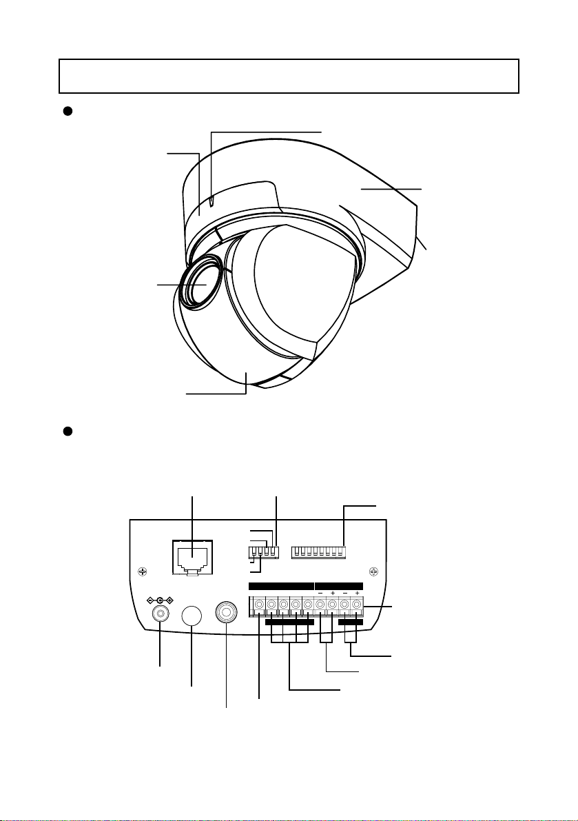
Overall View
- 5 -
1. PART NAMES AND FUNCTIONS
This camera is designed to mount on ceiling panels only.
Back Panel
LED
INFRARED SENSOR
BASE
BACK PANEL
LENS
CAMERA HEAD
ETHERNET
TERMINAL
(RJ45)
Ethernet
DC IN 12V
DIP Switch (4)
TERMINATE
RESET
ON
OFF
EXTENSION
N/A
VIDEO
OUT
RS-485 ID
87654321
ALARM RS-485
2 GND 1 GND
IN
DIP Switch (8)
ON
OFF
INOUT
TERMINAL BLOCK
DC IN
INFRARED SENSOR
COMPOSITE-VIDEO OUT
ALARM OUT TERMINAL
(RCA pin jack)
RS-485 IN TERMINAL
RS-485 OUT TERMINAL
ALARM IN TERMINAL
Page 7
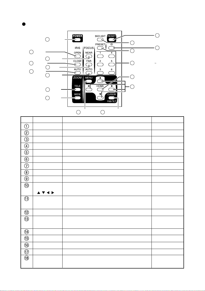
Wireless Remote Controller
- 6 -
POWER
1
OPEN
2
CLOSE
3
AUTO
4
NEAR
5
FAR
6
AUTO
7
TELE
8
WIDE
9
MENU
12
CURSOR/PAN-TILT
13
Directions
10
HOME
11
ID
17
RESET
15
BACK LIGHT
14
PRESET
16
NUMBER (1 6)
18
Function
To turn ON/OFF the Camera power.
To open the iris manually.
To close the iris manually.
To iris automatically.
To move the focus near.
To move the focus far.
To focus automatically.
To zoom in.
To zoom out.
To change the Camera head direction.
To operate the OSD
*1
cursor.
To turn the Camera head to the front.
To operate the OSD*1cursor.
To turn ON/OFF the OSD*1display.
To switch the operation mode between the menu
operation and the PAN-TILT operation.
Back light control.
To readjust the Camera head and LENS position.
To register the preset.
To operate multiple Cameras individually.
To set the preset position and the ID No.
Reference Page
P.14, P.19
P.16
P.16
P.16
P.16
P.16
P.16
P.16
P.16
P.15
P.19, P.20, P.21
P.15
P.19, P.20, P.21
P.18, P.19, P.20, P.21
P.19
P.17, P.20
P.15
P.17
P.14, P.18
P.17, P.18
Button Name
POWER
OPEN
CLOSE
AUTO
NEAR
FAR
AUTO
TELE
WIDE
Direction
()
HOME
MENU
CURSOR/
PAN-TILT
BACK LIGHT
RESET
PRESET
ID
NUMBER
(1~6)
No.
*1 OSD (On-Screen Display)
Page 8
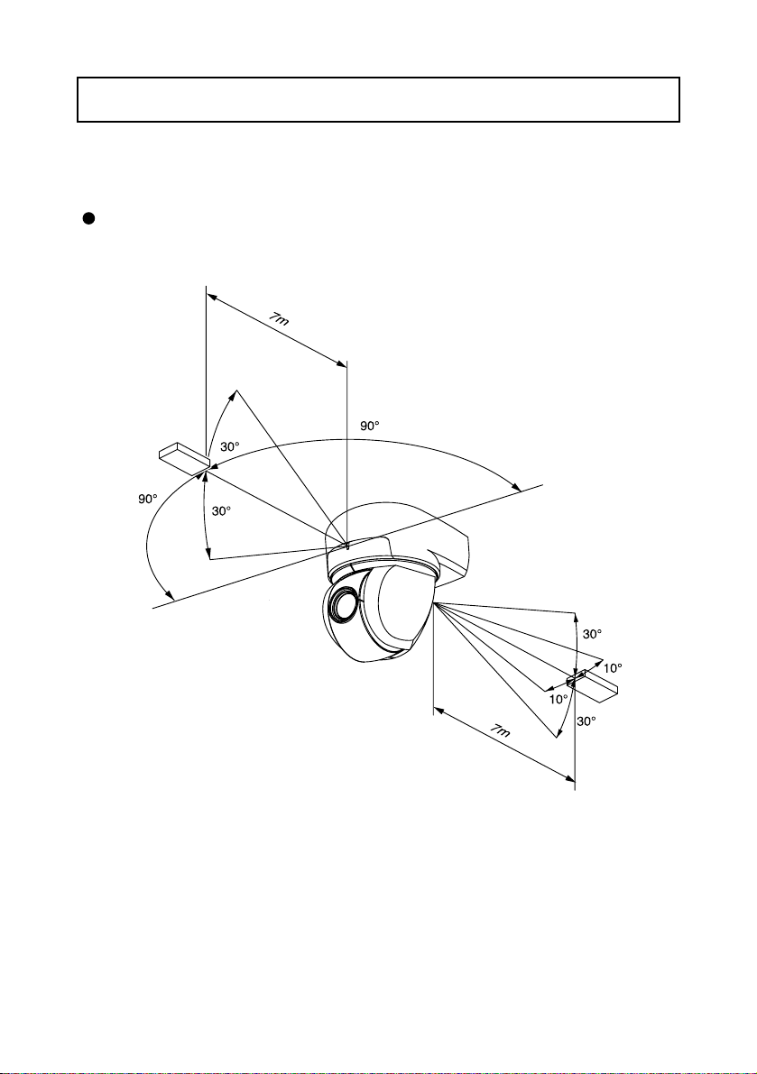
Point the infrared emitting window of the wireless remote controller at the infrared sensor
of the Camera, located at the front, and the rear panel, and select the desired function.
Receivable range
- 7 -
2. WIRELESS REMOTE CONTROLLER
Note: The infrared sensors may receive the infrared rays only within a narrower
receivable range or may not receive them at all depending on the ambient
environment, such as being placed under the sunlight or near an inverter
fluorescent lamp. In such case, relocate the installation place of the
receiving side or block off the sunlight.
Page 9

- 8 -
Preparation
Remove the battery case cover by pressing downward on the [ ] mark part in the
direction as indicated by the arrow.
Install 2 pcs. of batteries (type R03,AAA) into the case in the direction as indicated
there.
Note: Install the batteries with the proper to and to polarity.
Note: For dry cells, be sure to use the size AAA.
Note: Change the batteries at least once a year or when even nesessary.
Note: The batteries supplied with the Camera are only for use in initially
confirming the operation of the Camera.
It is not guaranteed that these batteries will work effectively for the
indicated period.
When multiple Cameras are operated through the wireless remote
controller
Refer to "5. THE ID NUMBER SETTING" on P. 18.
Page 10
- 9 -
3. SETTING UP
Note: When carrying the Camera, be sure to hold the base.
Note: Do not turn the Camera head in the PAN-TILT direction by hand, or
the Camera head may be broken.
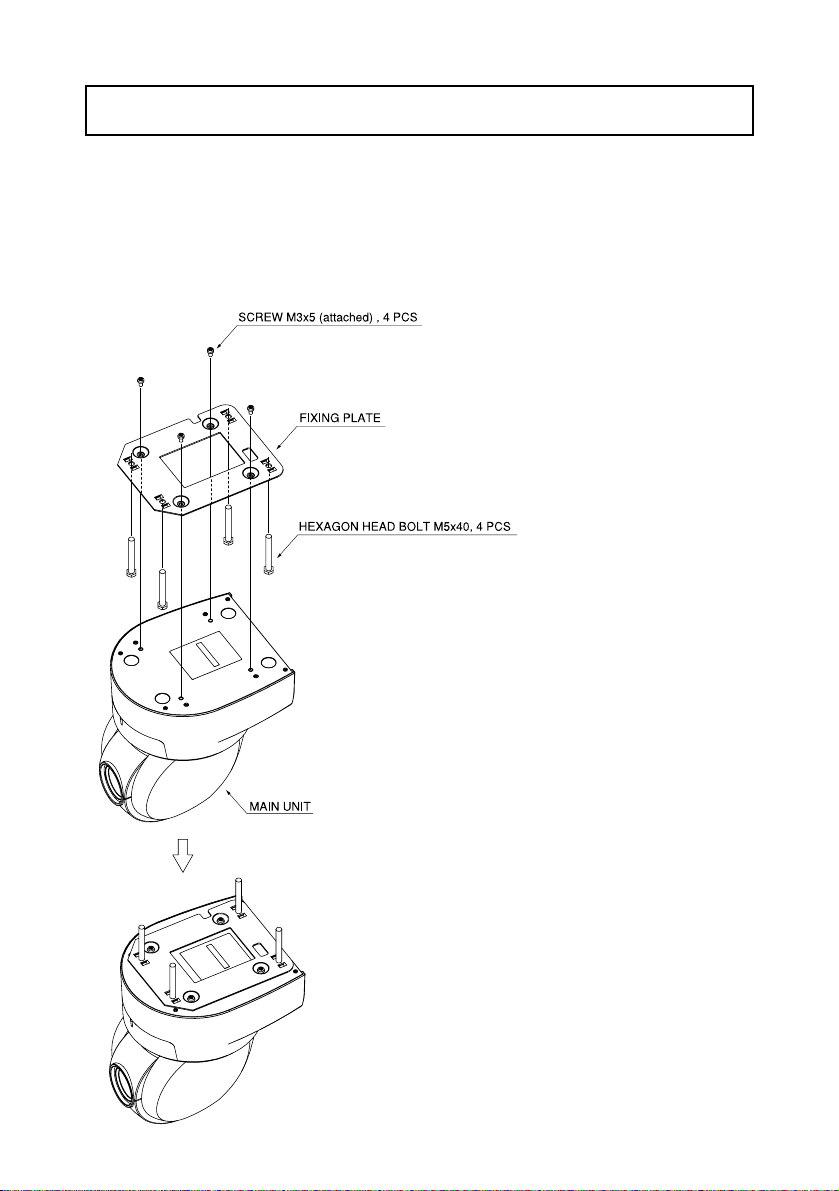
• Put 4 Hexagon Head Bolts M5x40 (supplied)
through the Fixing Plate, and screw the Fixing
Plate to the Main Unit with 4 Screws M3x5
(supplied).
Note: For fastening the Fixing Plate, be
sure to use the 4 Phillips-head
Screw M3x5 (supplied). Be careful
that using any screws other than
the supplied may damage the
inside of the Main Unit. (Do not use
longer screws)
(1) Mounting the Fixing Plate
[1] Installation
Page 11
- 10 -
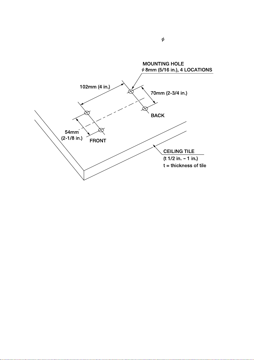
•
Make 4 holes of 8mm (5/16 in.) to the
Ceiling Tile as shown.
(2) Making mounting holes to the Ceiling Tile
Page 12
- 11 -
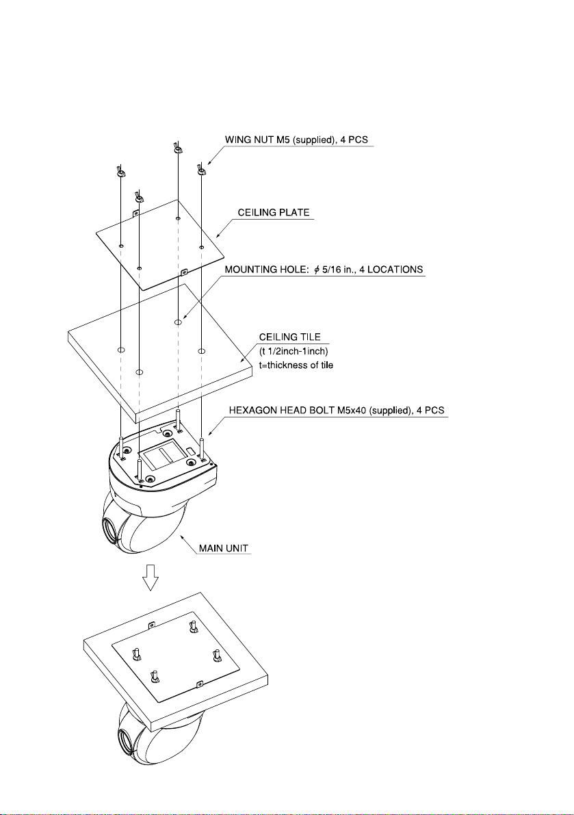
• Put the Ceiling Tile between the Main Unit
and the Ceiling Plate, and fix the Main Unit by
fastening 4 wing Nuts.
(3) Fixing the Main Unit
Page 13
- 12 -
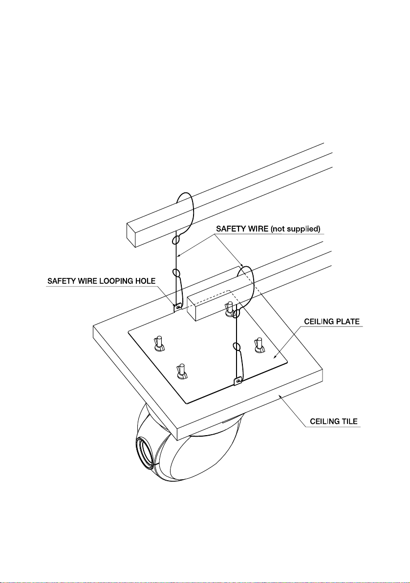
• Loop up one end of the Safety Wires through
the respective safety wire looping holes made
on the Ceiling Plate, and then loop up the other
end of the same around the beams or anything
that is used to mount ceiling tile channel for
structure safety.
(4) Mounting the Safety Wires
Page 14
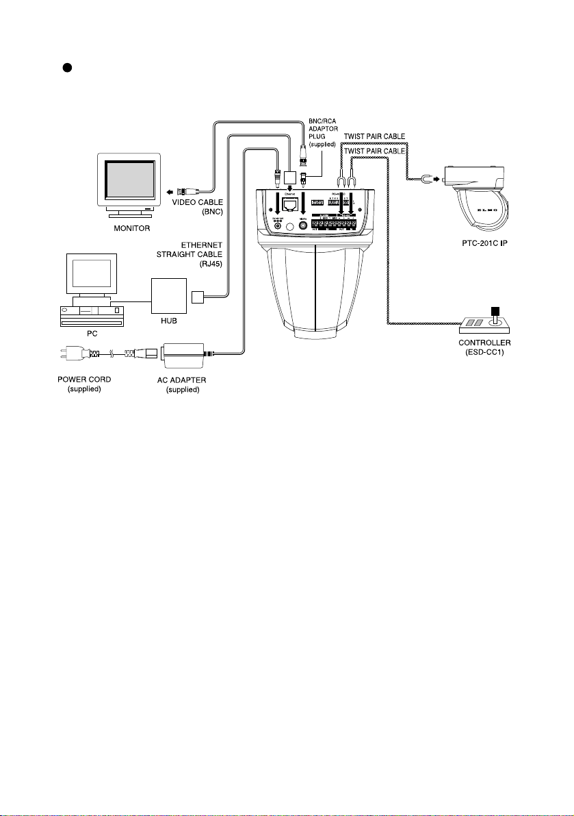
- 13 -
Connection examples for the Camera
Page 15
- 14 -
[1] Power supply to the Camera
The Camera has no POWER switch. Power is supplied to the Camera when the AC
adapter is connected to the wall socket and the Camera.
When power is supplied to the Camera, the Camera turns to the right and then to the
center automatically (viewed from the front), returning the Camera position to the
default home position.
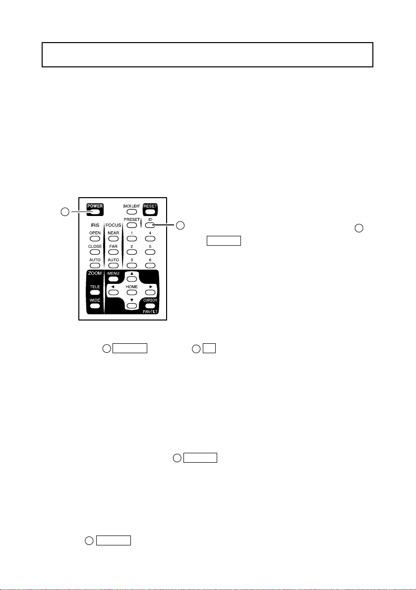
4. OPERATION PROCEDURES
(1) Turning OFF the Camera
• When the Camera is ready for operation
through the wireless remote control and
POWER button is pressed, the Camera
power is turned OFF. (However, even after
the Camera is turned OFF, power is still
being supplied to the Camera as power
supply to the Camera is not OFF.)
• The image disappears, and the LED on the
Camera lights up in red. Now, no buttons on
the wireless remote control are functional
1
[2] Turning ON/OFF of the Camera power
1
17
other than POWER button and ID button.
• When the TIMER OFF function is ON (refer to the settings in the OSD Menu screen),
Camera power is turned OFF automatically upon the lapse of the set time.
Note: When the Camera is not in use, make it a rule to keep the Camera
OFF. This will save power consumption. When the Camera is not to
be used for a long time, it is advisable to unplug the AC adapter to
render the Camera OFF.
(2) Turning ON the Camera
• When the Camera is OFF and POWER button is pressed, the Camera power is
turned ON.
• The image appears, and the LED on the Camera goes out. Now, the Camera is ready
for operation of all functions through the wireless remote control.
• If the ID number is changed (Refer to "5. THE ID NUMBER SETTING" on P.18), the
Camera power may not be turned ON. In such case, redo the ID number setting, and
press POWER button.
1
1
17
1
Page 16
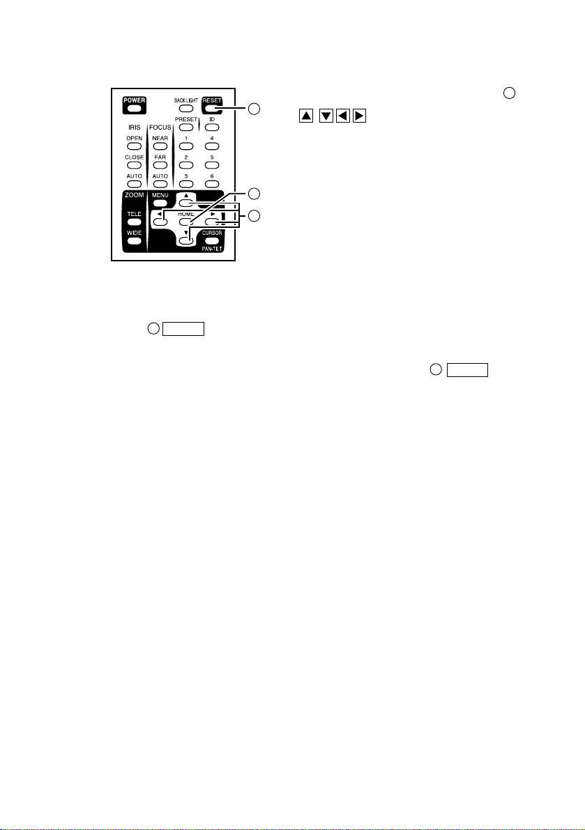
- 15 -
[3] Operating PAN/TILT
• While watching the screen, press any of
(UP, DOWN, LEFT, RIGHT)
direction buttons for the direction in which
you want to watch the image.
• To change the direction minutely, jog the
direction button. To change the direction
largely, hold down the direction button.
• Two operation modes are available
according to the speed: AUTO mode
changing the speed according to the zoom
position, and MANUAL mode setting the
speed manually. (Refer to the settings in the OSD Menu screen.)
• When HOME button is pressed, the Camera turns to the front (and the lens
moves to the WIDE side).
• If the Camera direction is changed manually by mistake, press RESET
button. Then, the Camera remembers the last PAN/TILT position in memory.
15
11
15
11
10
10
Page 17

- 16 -
[4] Lens operation
(1) Zoom operation
• The object is zoomed in (appears larger in the
screen) when TELE button of ZOOM is
pressed, or zoomed out (appears smaller in the
screen) when WIDE button of ZOOM is
pressed.
• When TELE button or WIDE button is
held down for over one second, the zoom speed
increases.
(2) Focus operation
• When AUTO button of FOCUS is pressed,
7
9
8
9
8
2
3
4
5
6
7
8
9
the FULL AUTO FOCUS status is established. (However, focusing may be
difficult for such objects as listed below.)
Objects with no contrast between light and
shade, such as white walls and night views
Objects reflecting an intensive light
Objects moving fast
Objects with many horizontal stripes, such as
blinds
Objects viewed through a glass pane with
water drops or stains
• To adjust the focus manually, press NEAR button or FAR button.
When NEAR button is pressed, the focus shifts near to you.
When FAR button is pressed, the focus shifts far away from you.
(3) Iris operation
• When AUTO button of the IRIS, the AUTO IRIS status (the brightness
remains unchanged even if the object is changed) is established.
• To adjust the iris manually, press OPEN button or CLOSE button.
When OPEN button is pressed, the iris opens.
When CLOSE button is pressed, the iris closes.
323
2
4
656
5
Page 18

- 17 -
[5] BLC (Back Light Control)
In case the back lighting is too bright to shoot the
main object clearly, press BACK LIGHT
button.
To cancel this mode, press the button.
14
[6] Preset operation
The Camera head direction, the zoom position, the
focus status and the brightness level can be
registered up to 6 items. The registration contents
remain retained even if the Camera power is
turned OFF.
(1) Setting presets
• Set the Camera head direction, the zoom
position, the focus status and the brightness
level.
• When PRESET button is pressed, the
LED on the Camera blinks in green (for 0.4
16
14
16
18
sec). To cancel this, press PRESET button again.
• Then, press one of the 1 through 6 buttons. Now, the registration is over, and
the LED on the Camera goes out. (The preset contents, if already registered, are
overwritten.)
(2) Execution of preset
• When one of the 1 through 6 buttons are pressed, the Camera head direction,
the zoom position, the focus status and the brightness level are set to that specific
preset position.
18
18
16
Page 19

- 18 -
5. THE ID NUMBER SETTING
When more than one Cameras are laid out adjacently and operated via the wireless remote
controller, the Cameras received the infrared rays operates in unison in the same way. When
each Camera is allocated with a different ID No., the Camera can be operated selectively
when its ID No. is specified via the wireless remote controller. The ID Nos. can be allocated
to up to 6 Cameras.
18
12
17
• Press ID button, and the LED's of all adjacent Cameras will start blinking (at
intervals of 0.2 sec). (To cancel this, press ID button again.) Then, press 1
through 6 buttons, and the LED's will go out, and selective operation by specifying
the ID No. will be ready. Now, only the selected Camera can be operated via the
wireless remote controller.
(3) Canceling the specific ID of the Cameras
• Hold down ID button for over 2 sec, and the blinking LED on the Camera will
light up. Then, unhand ID button. Now, the selective operation has been
cancelled, and all adjacent Cameras start operation via the wireless remote controller.
• Alternatively, the selective operation by specifying the ID No. can also be cancelled
by unplugging the DC jack from the Camera and turning ON the Camera power again.
171718
17
17
(1) Setting an ID No.
• Turn ON only the camera to be set with an ID
No. Leave other adjacent Cameras in the OFF
position. (Disconnect AC adapters, from the
Cameras or plug outlet.)
• Set the remote ID No. to the Camera. (See "6.
OSD (On-Screen Display)" on P. 19.) After
setting, close the Menu screen by pressing
MENU button. Then, repeat the ID No. setting
for all other Cameras in the same way.
(2) Operating the Cameras selectively
12
Page 20

- 19 -
6. OSD (On-Screen Display)
OSD Display menu
<<MAIN MENU>>
(1) MAIN CONTROL
(2) CAMERA SETUP SELECT ENTER (Return to MENU )
(3) TITLE SET
(4) PAN TILT MOTOR
(1) MAIN CONTROL SELECT ADJUST (Return to MENU )
<1> TITLE
<2> SELECT
<3> SET INDICATE
<4> REMOTE ID
<5> OFF TIMER
ON/OFF: To change the ON/OFF of the character in the
bottom of the screen.
PRESET/CAMERA: To change the title to be displayed.
(This setting is enabled only when the above TITLE is ON.)
PRESET: To display preset position names from 1 to 6.
CAMERA: To display the name of the Camera.
ON/OFF: To display the preset position in the screen upon
its registration (for about 2 sec).
1~6: To set the ID No. of the Camera for the selective
operation via the wireless remote control.
If the ID No. is not to be set, set this to "0."
(This has been factory set to "0.")
OFF, 5min, 10min, 30min 1h, 2h, 5h: To set the time for the
Low Power Consumption mode.
If no operation status continues longer than the above set
time, the Camera power will be turned OFF automatically.
To turn ON the Camera power again, press POWER
button. (This has been factory set to "OFF.")
The MENU button is used to turn ON/OFF
the OSD display. When the Sub menu is
displayed, the screen goes back to the previous
screen by using MENU button.
When the OSD display is available,
direction buttons and HOME button
function as the menu operation keys.
To halt the menu operation and perform the PAN-
TILT operation, press CURSOR/PAN-TILT
button. To resume the menu operation, press
CURSOR/PAN-TILT button again.
13
13
11
12
1
12
14
12
11
10
13
10
Page 21

- 20 -
(2) CAMERA SETUP SELECT ADJUST (Return to MENU )
<1> BLC
<2> AGC
<3> AP GAIN
<4> FL
<5> NEXT PAGE
<6> MEMORY
<7> CLEAR
<8> WB
To
change
the White
Balance
mode.
<9> R SHIFT *1
<10> B SHIFT *2
<11>
COLOR
To adjust
the color.
<12> PREVIOUS PAGE
ON/OFF: To balance the difference between light and dark
background.
This function can also be operated easily by pressing
BACK LIGHT button on the wireless remote control.
0dB, 4dB, 8dB, 12dB, 16dB, 20dB, 24dB: To adjust the
maximum AGC gain.
-6 to +9: To adjust the contour correction level between.
ON/OFF: To change the ON/OFF of the flicker correction.
To go to the next screen.
To save the current settings of the Camera by pressing
HOME button.
To reset the settings of the Camera to the factory-settings
by pressing HOME button.
To adjust the white balance by way of the automatic
following. (The white balance will not be effected by colors
of lighting changes.)
To adjust the white balance by way of one-push of button.
The white balance is adjusted once by selecting the AWC
mode and pressing HOME button. When the WB mode
has been changed or the R-SHIFT or B-SHIFT function has
been changed, the white balance must be adjusted again by
pressing HOME button.
To be used indoors. The color temperature is 3,200K.
To be used outdoors. The color temperature is 6,300K.
To be used under fluorescent lamps. The color temperature
is 4,200K.
±30: The larger this value is, the screen is more reddish.
±30: The larger this value is, the screen is more bluish.
±30 To adjust the intensity of red.
±30 To adjust the intensity of blue.
±30 To adjust the hue of red.
±30 To adjust the hue to blue.
To return to the previous screen.
1. ATW
2. AWC
3. INDOOR
4. OUTDOOR
5. LIGHT
1. R GAIN
2. B GAIN
3. RY HUE
4. BY HUE
Sets the alarm position time [10 sec (default), 20 sec, 30
sec, 1 min, 5 min, 10 min, OFF]. When the set time has
passed, automatic resetting is made to the lastly executed
preset position.
Sets the alarm signal output time [0.1 sec (default), 0.5 sec,
1 sec, 2 sec, 5 sec, 10 sec, 30 sec].
<6> ALARM IN
<7> ALARM OUT
Page 22

- 21 -
(3) TITLE SET
SELECT
ADJUST
(Return to MENU )
<1> MOTOR SPEED
<2> SPEED
<3> L/R DIRECTION
• To set the title for each preset position and Camera.
Make the title to be set blink, and press direction
button to go to the set character. Then, set the character
one by one by using direction buttons.
The types of characters that can be set are alphabetic
characters in capital and small ("A" through "Z" and "a"
through "z") and symbols (e.g., < > - / . :). After setting all,
press HOME button to save the settings.
(4) PAN TILT MOTOR SELECT ADJUST (Return to MENU )
• To set the motor speed when the PAN-TILT function is in
operation.
• AUTO: The operation speed can be changed automatically
according to the zoom position.
• MANUAL: The operation speed can be selected freely.
• To set the motor speed when "MANUAL" has been
selected for the motor speed. The motor speed can be
changed in 8 steps from 0 to 7.
• STANDARD/REVERSE: To change the PAN direction.
*1: <9> "R SHIFT" and <10> "B SHIFT" are available in 2 types, respectively: one for the
ATW and AWC functions, and the other for the INDOOR, OUTDOOR and LIGHT
functions. For example, it is possible to set "R SHIFT" to +10 in the ATW mode and
to ± 0 in the INDOOR mode.
*2: <11> "COLOR" is available for all modes irrespective of the mode of "WB".
*3: To change and save the Camera settings, be sure to press HOME button in the
>MEMORY display on the first screen.
Page 23

- 22 -
7. ALARM IN/OUT TERMINALS
By short-circuiting the ALARM 1 IN or ALARM 2 IN Terminal Block to the GND
terminal on the Terminal Block, the Camera moves to the allocated preset position.
• When short-circuiting the ALARM 1 IN terminal to the GND terminal,
the Camera moves to the preset position 1.
• When short-circuiting the ALARM 2 IN terminal to the GND terminal,
the Camera moves to the preset position 2.
Then, when the time set from the OSD menu has passed, the Camera moves back
automatically to the lastly executed preset position.
Terminal name
1 IN
GND
2 IN
OUT
Function
Inputs the alarm signal <1>.
Grounds.
Inputs the alarm signal <2>.
Outputs the alarm signal.
Signaling
GPI
-
GPI
Open-collector output
• Regarding time setting, refer to the setting in the OSD menu screen.
When the alarm input signal has been activated and the Camera has moved to the specified
position, the alarm signal is outputted at the ALARM OUT terminal for the time preset
from the OSD menu.
Pin arrangement
[1] Alarm input
[2] Alarm output
(1) Regarding time setting, refer to the setting in the OSD menu screen.
(2) Signal specification
Max 12V, 30mA (open-collector output)
Page 24

- 23 -
DIP Switch (4)
8.
INITIALIZATION OF THE CAMERA SETTINGS
The camera settings can be initialized with the DIP switch (4) located on the back panel.
• In the power supply OFF state (the AC adapter is not connected), turn ON the RESET
switch.
• Turn on the power supply (connect the AC adapter), and 10 seconds later, turn OFF
the power supply.
• When the power supply is turned on again, the PAN/TILT settings, lens settings,
preset settings, and camera settings by the OSD (on-screen display) are reset to
factory-shipped condition.
Note: After the initialization, be sure to turn OFF the RESET switch. If the
switch remains ON, every time the power supply is turned on, the
settings are initialized, so that each setting is not stored.
Note: The extension switch and N/A switch not in use must be kept OFF.
Note: When this operation is performed, the “initialization of the network
settings” (page 32) is also carried out at the same time.
Switch No.
EXTENSION
N/A
RESET
TEMINATE
Normal
OFF
OFF
OFF
OFF
Operation
ON
Kept OFF
ON OFF
ON
Function
RSU-200 (optional) mode
-
Initialization of settings
Terminator setting (see P.25.)
Switch assignment
Page 25

- 24 -
This system can be controlled from the controller by connecting the RS-485 terminal on the
Terminal Block to the controller via an RS-485 converter.
Make the connection as shown below.
Each camera can be set for the ID address via the DIP Switch (8) located on the bottom so
that a selected camera can be controlled.
Up to 223 Cameras can be controlled from one controller.
To raise the reliability, connect the DATA (+)and the DATA (-) with a twist pair cable.
To protect this system and the controller, be sure to turn OFF the POWER switches of all
units before starting the connection.
9. RS-485
Communication specifications
• Communication mode: Synchronous half duplex
• Communication speed: 9600bps
• Start bit: 1 bit
• Stop bit: 1 bit
• Parity bit: None
Pin assignment
Terminal name
+IN
-IN
+OUT
-OUT
GND
Signal name
DATA (+)
DATA (-)
DATA (+)
DATA (-)
GND
Function
+ side: Inputs the transmitted/received
- side: Inputs the transmitted/received
+ side: Outputs the transmitted/received data.
- side: Outputs the transmitted/received data.
Grounds.
If you need the data format specifications and the command table, please contact our
distributor.
Page 26

- 25 -
10.
TERMINATING RESISTANCE AND ID ADDRESS SETTINGS
[1] Setting the terminating resistance
The terminating resistance is built in each Camera, and it can be turned ON/OFF by using
TEMINATE switch of the DIP Switch (4) of each Camera. To prevent the attenuation of the
signal, turn ON the terminating resistances of the Camera located at end of the longest
route, of all cameras to be connected to the RS-485 interface, and turn OFF the terminating
resistances of the other Cameras.
[2] Setting the ID address
The ID address for communication of the RS-485 can be set by using the switches No. 1
through 8 of the DIP Switch (8). (Refer to "Setting the ID address" table - P26, 27)
DIP Switch (4)
DIP Switch (8)
Page 27

- 26 -
Setting the ID address
Page 28

- 27 -
Page 29

- 28 -
11. NETWORK FUNCTIONS
By connecting this Camera to the network using Ethernet (10BASE-T/100BASE-TX), the
following functions are made available from the host (e.g., PC) on the network:
• Web server functions – Displaying moving images, displaying static images, quad
disply and operating remote control through the Web browser.
• Alarm function - Saving image files to the remote host by input of the alarm signal.
• IP address filtering functions - Restricting clients who have access to the Camera.
•
LIVE connection list - Listing the clients connected to the LIVE page.
• telnet server functions – Operating remote control and acquiring status data.
Note: It is not assured that this Camera can be connected to all units on the
network.
Note: The applicable Web browsers are Internet Explorer 4.0 and newer and
Netscape 6.0 and newer. For any other browser, consult your dealer or an
authorized ELMO service center.
[1] Preparation for connection
Before connecting the Camera to the network for use, the network must be set up (e.g., IP
address).This Camera provides two procedures for setting up the network as follows:
• Connecting the Camera from the host on the network through the Web browser.
• Connecting the Camera from the host on the network through telnet.
Here, the setup procedure using the Web browser is described.
For the setup procedure using telnet,
consult your dealer or an authorized ELMO service center.
Preparation before setting up
Before starting the setup, specify the IP address and subnet mask to be set up in the Camera.
For the IP address and subnet mask to be specified, ask the administrator of the network to
be used.
This Camera has been factory set on the network as follows:
IP address 192.168.0.100
Subnet mask 255.255.255.0
If the network address of the network to be used is not 192.168.0.0 or if there is any other
host with the IP address 192.168.0.100 is already in operation on the same network, this
Camera cannot be connected to the network for setup. In this case, a network with the IP
address 192.168.0.0 must be configured with this Camera and the host for setting up this
Camera. Prepare a host having the IP address 192.168.0.X (X: 1~254, excluding 100) and
the subnet mask 255.255.255.0, and connect such host to the Camera.
Page 30

- 29 -
Connection to the network
• Connection using HUB
Connect the Ethernet terminal (RJ-45) of the Camera to the HUB port with an
Ethernet straight cable (UTP Category 5). For the HUB port, use a port other than the
MDI port.
• Connection to one host
Connect the Ethernet terminal (RJ-45) of the Camera to the Ethernet terminal of the
host with an Ethernet cross cable (UTP Category 5).
Setting up of the network
• Start the Web browser from the host
connected to the Camera.
•
Enter the IP address or host name (if
allocated) of the
Camera
, following
[http://], followed by [/config.htm], in
the Address bar’s text box of the Web
browser.
For example, enter the IP
address of this Camera as
“http://192.168.0.100/config.htm” since
it has been factory set to 192.168.0.100.
• When configuration page is displayed
in the Web browser, click the link
[Network Configuration].
Note: Upon connection of this Camera to other unit on the network through the
Ethernet terminal, the communication protocol is adjusted automatically
between the Camera and the connected unit to 10BASE-T/100BASE-TX and
HDX/FDX (i.e., “automatic negotiation”). Therefore, this Camera may not be
properly connected to some units on the network that do not comply with
automatic negotiation.
Page 31

- 30 -
• When [Network Configuration] is displayed, change the set values according to the
environment of the network to be used. To reset the changed set values to the original
set values, click the clear button [CLEAR].
• When all items have been set, click the submit button [SUBMIT].
When the message “The saving of the setup was completed. Please restart.” is
displayed, the setting up of the network is completed. Being as restarted
automatically, it will be accessible on the updated settings about one minute later.
If the message “Incorrect value of setting exists. Please set up again.” is displayed
when the submit button [SUBMIT] is clicked, there is an incorrect value entered for
setting. Go back to [Network Configuration] and redo the setting.
Reference Page [7] Configurations Network Configurations P.43
Note: If there are more than one unit with the same IP address on the network, a
disorder would be caused to the network. Therefore, set the IP address
carefully.
Note: Once the submit button [SUBMIT] is clicked, do not turn OFF the power supply
until the next screen is displayed. Otherwise, the set values will be destroyed
and connection from the network will be disabled. If the connection is disabled,
reset the settings to the factory settings by referring to “Initialization of Network
Settings” in the next section, and the redo the setting.
Page 32

- 31 -
Initialization of the network settings
If the connection from the network is disabled due to destruction of the network settings or
disremembering of the set value, reset the settings to the factory settings by using the
following procedure and then redo the settings:
• If the Camera is in connection to the network, disconnect the Camera from the
network.
• In the power supply OFF state, turn ON the RESET switch located on the backside of
the Camera.
• Turn ON the power supply, and wait for approx. 10 seconds.
• Turn OFF the power supply, and turn OFF the RESET switch.
• Turn ON the power supply again. Then, the network settings, IP adrress filtering
setting, alarm setting, quad display setting are reset to the factory settings.
Note: After the initialization, be sure to turn OFF the RESET switch. If the switch
remains ON, every time the power supply is turned on, the settings are
initialized, so that each setting is not stored. Besides, the connection from the
network is disabled.
Note: When this operation is performed, the camera settings are also initialized.
(Refer to [8] “Initialization of the camera settings” on page 23.)
[2] Web server functions – Displaying moving images, displaying
static images, quad disply and operating remote control through the
Web browser.
When the Camera is connected from the Web browser, moving images can be displayed,
static images cab be displayed, and remote control can be operated. To connect the Camera
from the Web browser, enter the IP address or host name (if allocated) of the Camera,
following [http://], in the address column of the Web browser provided for entering the
URL to be opened. Then, the PTC-201C IP page is displayed. Click the desired link there.
Then, the selected function can be used.
If the password has been set on the [Network Configuration], the Authentication page is
displayed. In that case, if authentication by the [root], [operator], or [user] account is
cleared successfully, the Web server functions can be used.
Reference Page [7] Configurations Network Configurations P.43
Note: Since no password is factory set, the Authentication page is not displayed.
Page 33

- 32 -
Display of static images
By clicking the links [VGA] and [QVGA] of CAPTURE at the PTC-201C IP page, and the
LIVE page, the static images of 320X240 and 640X480 in size can be displayed,
respectively. To save the static image, use the function of the Web browser.
When any link at the PTC-201C IP page is clicked, the static image is displayed in the same
window. However, when any link at LIVE pages is clicked, another window opens, and the
static image is displayed in that window.
Display of moving images (LIVE page)
By clicking the link [QVGA] next to *LIVE
on the “PTC-201C IP” page or the link
[QVGA] next to MONITOR SIZE on the
LIVE page, the QVGA (320X240) moving
live image page can be displayed. Moreover,
by clicking the link [VGA] next to *LIVE or
the link [VGA] next to MONITOR SIZE on
the LIVE page, the VGA (640X480) moving
live image page can be displayed.
However, to display moving images, Java
must have been set enabled.
Moving images can be displayed
simultaneously at up to 10 clients. If more clients access the Camera, the screen displays the
message “Maximum number for LIVE image now accessing. Please wait”
The frame rate of the Moving image is max. 30 frames per second. However, the frame rate
depends on the processing capacity of the host, the network environment, the number of
connections units, etc.
Note: If the power supply to the Camera is turned OFF while the moving image is in
display, the host displaying the moving image may, depending on the Web
browser in use, continue the internal processing even if the Web browser is
closed. Normally, this causes no problem. However, if this is repeated again
and again, the operation of the host may be destabilized. If the host becomes
unstable, restart the host.
Note: When moving images break up for some reason, moving display section in
the browser gets black.
Page 34

- 33 -
Operation of remote control
When on the LIVE page the mark CONTROL is displayed above the [HOME] button,
remote control is enabled. For display/non-display of the mark CONTROL , refer to the
next paragraph “About control”.
Page 35

- 34 -
(1) Zoom operation
Clicking the buttons effects zoom operation. Clicking the TELE (T-) buttons and the
WIDE (-W) buttons provides zoom-in and zoom-out operation, respectively. The
buttons or coarse control buttons enable the zoom position to change by a large
amount, and the buttons or fine control buttons permit the zoom position to
change by a small amount.
(2) Iris operation
By clicking the buttons , the iris can be adjusted manually. Clicking the OPEN (-O)
buttons opens the iris diaphragm, and clicking the CLOSE (C-) buttons closes the iris
diaphragm. The buttons or coarse control buttons enable the lens aperture to
change by a large amount, and the buttons or fine control buttons permit the
lens aperture to change by a small amount. Clicking the AUTO IRIS button
brings the camera into the Auto Iris mode.
(3) Focus operation
By clicking the buttons , the focus can be adjusted manually. Clicking the NEAR
(N-) buttons and the FAR (-F) buttons shifts the focus toward you and away from you,
respectively. The buttons or coarse control buttons enable the focus shift to
change by a large amount, and the buttons or fine control buttons permit the
focus shift to change by a small amount. Clicking the AUTO FOCUS button
brings the camera into the Auto Focus mode.
(4) Move operation
By clicking the 1 to 6 buttons , the camera can be moved to the registered preset
position assigned to each button.
(5) Operating PAN/TILT
To move the camera while watching the moving image, drag the slider boxes
horizontally and vertically on the scroll bars and . When the mouse button is
clicked on some point within the area, the marker moves to the point on which the
mouse button was clicked, and the camera also moves to the position corresponding that
point. Clicking the RESET button matches the PAN/TILT position stored in the
camera with the actual position. Clicking the HOME button orients the camera
frontward.
879
11
10
65432
1
Page 36

- 35 -
About control
Remote control of the Camera can be accomplished by only one client. Control is given to
the client who satisfies the following conditions.
• Client who has been authenticated by the [root] or [operator] account in the case
where the password is specified for [operator] or [user] on [Network Configuration]
page. (Refer to the paragraph “Network Configurations” in [7] “Configurations” on
page 43.)
• All clients when in as-shipped condition (no password is set).
Control is transferred on an earlier authenticated client basis.
For example, in the case where the client who obtained control when multiple clients were
displayed on the LIVE page leaves the LIVE page, control is transferred to the client
displayed in the mode incapable of remote control. Then, it is undefined to which client
control is transferred next.
Note: Depending on network environments, control is not transferred immediately.
Page 37

- 36 -
Quad display
By clicking the link [QUAD] next to *LIVE on the “PTC-201C IP” page or the link
[QUAD] next to MONITOR SIZE on the LIVE page, the Quad Display page can be
displayed.
Before utilizing this function, the setting of quad display must be made.
The Camera provides the following two procedures for quad display setting.
• Connecting to the Camera from the host on the network through the Web browser.
• Connecting to the Camera from the host on the network through telnet.
Here, the setup procedure using the Web browser is described.
For the setup procedure using telnet, consult your dealer or an authorized ELMO service
center.
(1) Setting
• Enter the IP address or host name (if allocated) of the Camera, following [http://],
followed by [/config.htm], in the Address bar’s text box of the Web browser.
For example, enter the IP address of this Camera as
“http://192.168.0.100/config.htm”, since it has been factory set to 192.168.0.100.
• When the Authentication page is displayed, undergo authentication by the [root]
account. Authentication cannot be cleared successfully by any other account. (The
Authentication page is not displayed, since no password has been set in as-shipped
condition.)
• When the Configurations page is displayed in the Web browser, click the link [Setting
for quad display].
• When the “Setting for quad display” page is displayed, enter camera settings for the
images to be displayed on the upper-left, upper-right, lower-left, and lower-right
screen segments. To reset the changed settings to the original settings, click the clear
button [CLEAR].
• When all items have been set, click the submit button [SUBMIT]. When the message
“The saving of the setup was completed.” is displayed, the setting of quad display is
completed. The updated settings are effective. Click the link [Configurations] to go to
the Configurations page.
If the message “Incorrect value of setting exists. Please set up again.” is displayed
when the submit button [SUBMIT] is clicked, there is an incorrect value entered for
setting. Go back to the “Setting for quad display” page and redo the setting.
Reference Page [7] Configurations Setting for quad display P.45
Note: In the case where is an NAT router between this Camera and other camera
registered in the Camera setting for quad display, change the IP address of
other camera to be registered, to the IP address of this Camera router, and
specify it. If a host name is allocated to the camera to be registered, specify
that host name. For the IP address and host name of this Camera-side router,
consult the network administrator.
Page 38

- 37 -
(2) Operation
• The cameras specified on the [Setting for quad display] page are displayed. (The
upper-left screen segment always displays moving images provided by the Camera.)
• When the mouse’s left button is clicked on a screen segment, the static image of
that clicked image is displayed in another window. The resolution of that static
image is the resolution selected on the [Setting for quad display] page.
• When the mouse’s right button is clicked on a screen segment, the LIVE page for
that clicked image appears. The resolution of that moving image is the resolution
selected on the [Setting for quad display] page.
Page 39

- 38 -
[3] Alarm function - Saving image files to the remote host by
input of the alarm signal
By shorting the alarm signal input terminal <1> or <2> on the back panel of the
Camera
to
the GND terminal, the
Camera
can be moved to the preset position assigned to each
terminal. (Refer to [1] “Alarm input” in paragraph 7 “ Alarm in/out terminals” on page 22.)
At this time, it is possible to save image files to the host on the network specified for File
Transfer on the Alarm Configuration page. When this function is utilized, the FTP server
must be in operation in the host at the saving destination.
Note: If alarm signals are input continuously at short intervals, the image
corresponding to the preset position cannot be saved in some cases.
Also, all the images as many numbers as alarm inputs could not be saved in
some cases.
Note: Image could not be saved on some network conditions.
The
Camera
provides the following two procedures for alarm setting.
• Connecting to the
Camera
from the host on the network through the Web browser.
• Connecting to the
Camera
from the host on the network through telnet.
Here, the setup procedure using the Web browser is described.
For the setup procedure using telnet, consult your dealer or an authorized ELMO service
center.
Setting
• Enter the IP address or host name (if allocated) of the
Camera
, following [http://],
followed by [/config.htm], in the Address bar’s text box of the Web browser. For
example, enter the IP address of this
Camera
as “http://192.168.0.100/config.htm”,
since it has been factory set to 192.168.0.100.
• When the Authentication page is displayed, undergo authentication by the [root]
account. Authentication cannot be cleared successfully by any other account. (The
Authentication page is not displayed, since no password has been set in as-shipped
condition.)
• When the Configurations page is
displayed in the Web browser, click the
link [Alarm Configuration].
• When the Alarm Configuration page is
displayed, specify whether to enable or
disable the alarm action. To disable the
alarm action, select the radio button
[No action]. To enable it, select the
radio button [File transfer]. To reset
the changed settings to the original
settings, click the clear button
[CLEAR].
Page 40

- 39 -
• After the selection, click the submit
button [SUBMIT]. If [No action] is
selected, when the message “The
saving of the setup was completed.”
is displayed, the setting of the alarm
function is completed. If [File
transfer] is selected, the File Transfer
Setting Input page is displayed.
• When the File Transfer Setting Input
page is displayed, change the set
values according to the host at the
saving destination. To reset the
changed set values to the original set values, click the clear button [CLEAR].
• When all items have been set, click the submit button [SUBMIT]. When the message
“The saving of the setup was completed.” is displayed, the setting of file transfer is
completed. If the message “Incorrect value of setting exists. Please set up again.” is
displayed when the submit button [SUBMIT] is clicked, there is an incorrect value
entered for setting. Go back to the File Transfer Setting Input page and redo the
setting.
Reference Page [7] Configurations Alarm Configurations P.43
Reference Page [7] Configurations
File transfer Configurations P.44
Note: Image could not be saved on some network conditions.
Page 41

- 40 -
[4] IP address filtering functions - Restricting clients who have
access to the Camera
This function is intended to restrict clients who have access to the
Camera
. By registering
the IP address allocated to each client, access to the
Camera
can be permitted. The number
of clients that can be registered is limited to 10. One of those clients is granted
administrative privileges.
Reference Page [7] Configurations
IP address filtering Configurations P.43
The
Camera
provides the following two procedures of setting the IP address filtering
function.
• Connecting to the
Camera
from the host on the network through the Web browser.
• Connecting to the
Camera
from the host on the network through telnet.
Here, the setup procedure using the Web browser is described.
For the setup procedure using telnet, consult your dealer or an authorized ELMO service
center.
Setting
• Enter the IP address or host name (if allocated) of the
Camera
, following [http://],
followed by [/config.htm], in the Address bar’s text box of the Web browser. For
example, enter the IP address of this
Camera
as “http://192.168.0.100/config.htm”,
since it has been factory set to 192.168.0.100.
• When the Authentication page is displayed, undergo authentication by the [root]
account. Authentication cannot be cleared successfully by any other account. (The
Authentication page is not displayed, since no password has been set in as-shipped
condition.)
• When the Configurations page is
displayed in the Web browser, click
the link [IP Address Filtering
Configuration].
• When the IP Address Filtering
Configuration page is displayed, enter
the IP addresses for which access to
the
Camera
is permitted. To reset the
changed settings to the original
settings, click the clear button
[CLEAR].
• When all items have been set, click the
submit button [SUBMIT]. When the IP
address for the administrator is
changed, the message “You are now
Page 42

- 41 -
about to change the IP address for the administrator.” or other message is displayed.
Confirm the changed IP address for the administrator. If it checks OK, click the [Yes]
button.When the message “The saving of the setup was completed.” is displayed, the
setting of the IP address filtering function is completed. If the message “Incorrect
value of setting exists. Please set up again.” is displayed when the submit button
[SUBMIT] is clicked, there is an incorrect value entered for setting. Go back to the IP
Address Filtering Configuration page and redo the setting.
Reference Page [7] Configurations
IP address filtering Configurations P.43
Note:
When updating the IP address for the administrator on the IP Address
Filtering Configuration page, exercise added care in setting. If the IP
address for the administrator cannot be remembered, it is impossible to
go to the Configurations page. In this case, follow the step “Initialization
of the network”.
Reference Page [1] Preparation for connection
Initialization of the network setting P.31
Page 43

- 42 -
[5] LIVE connection list - Listing the clients connected to the
LIVE page
This function is intended to display in list form the IP addresses of the clients connected to
the LIVE page of the
Camera
, the authenticated clients, and the duration of connection.
Also, if a client connected has an unauthorized address, it is possible to break the
connection from on the list.
Display method
• Enter the IP address or host name (if allocated) of the
Camera
, following [http://],
followed by [/config.htm], in the Address bar’s text box of the Web browser. For
example, enter the IP address of this
Camera
as “http://192.168.0.100/config.htm”,
since it has been factory set to 192.168.0.100.
• When the Authentication page is displayed, undergo authentication by the [root]
account. Authentication cannot be cleared successfully by any other account. (The
Authentication page is not displayed, since no password has been set in as-shipped
condition.)
• When the Configurations page is displayed in the Web browser, click the link [LIVE
[6]
telnet server functions – Performing remote operation and
acquiring the status
This Camera can be remotely controlled and its status can be acquired through telnet.
For the information of the command, etc., consult your dealer or an authorized ELMO
service center.
Connection List].
• When the LIVE connection list
appears, the number of clients
connected, the IP address, account,
and duration of connection, of each
client, are displayed in list form.
When the refresh button is clicked,
the contents of the list are updated.
When there is a client connected,
the [Disconnect] button is shown in
the rightmost column of the list. In
order to avoid the LIVE page from
being seen because of an
unauthorized address or for other
reason, click the [Disconnect]
button to break the connection to
that client.
Page 44

- 43 -
[7] Configurations
Network Configurations
IP address filtering Configurations
Alarm Configurations
Item Outline
IP Address
Subnet mask
Default
Gateway
Port for the
Web server
root password
operator
password
user password
The IP address of the Camera.
Specifies the value allocated by the administrator of the network in use.
Factory set to 192.168.0.100.
The mask value for separating the network address from the host address.
Used in combination with the IP address to specify the network to which this Camera
belongs.Specifies the value allocated by the administrator of the network in use.
Factory set to 255.255.255.0.
Specifies the IP address of the router when this Camera is used on the network equipped with a
router. For the IP address of the router, ask the administrator of the network to in use. Factory
set to 0.0.0.0. Set to 0.0.0.0. when using the Camera on the network equipped with no router.
Specifies the port number to access the Web server of the Camera. When “Default” is selected,
the port number of 80 is assigned. When specifying an arbitrary port number, consult the
administrator for the network to be used.
The password for using Change of the settings, Camera control functions, Display of the LIVE
page, Display of static images, and telnet.Not factory set.
Should preferably be set for the security purpose.
The password for using Camera control functions, Display of the LIVE page, and Display of
static images.
Not factory set.
The password for using Browsing of the LIVE page and Obtaining of static images.
Not factory set.
Item Outline
IP filtering
Access
permitted IP
address 1
(for administrator)
Access
permitted IP
address 2 to
Access permitted
IP address 10
Specifies whether to enable or disable the IP address filtering function.
Factory set to Disable.
Registers the IP address of the client to whom administrative privileges are granted. The
registered client can use Display and Change of the settings, Camera control functions,
Display of the LIVE page, Display of static images, and telnet.
Factory set to 0.0.0.0.
Registers the IP address of the client who can use Camera control functions, Display of the
LIVE page, and Display of static images. Even if the client registered here is authenticated by
the [root] account, that client cannot use Display and Change of the settings, and telnet.
Factory set to 0.0.0.0.
Item Outline
Alarm action
Specifies whether not to effect the alarm action or to transfer images by File transfer. Factory
set to No action.
Page 45

- 44 -
File transfer Configurations
Item Outline
IP address of
image receiving
Specifies the IP address of the destination host to save.
Factory set to 0.0.0.0.
server
Port number of
image receiving
server
Account of
image receiving
Specifies the port number used by the FTP server in operation at the destination host to save.
Normally, no need to be changed.
Factory set to 21.
Specifies the account name used for connection to the destination host to save.
Factory set to anonymous.
server
Password of
image receiving
Specifies the password of the above account.
Not factory set
server
Passive mode
Directory to
save
Resolution
File name
Add sequential
number to file
name?
First number of
sequence
Last number of
sequence
Specifies which mode is used for file transfer, the passive mode or active mode. When the port
is limited by firewall, etc., use the passive mode. For whether the passive mode should be used
or not, ask the administrator of the network in use.
Factory set to no use.
Specifies the directory to save the image file. Specifies the write-enabled directory of the
assigned account. Not factory set. (The root directory has been specified.)
Specifies the resolution of the image to be saved, from among VGA and QVGA. The
resolution is 640X480 for VGA and 320X240 for QVGA.
Factory set to VGA.
Specifies the name of the file to be saved. Automatically adds the extension [.jpg] to the file
name. Since any file under the same name in the saving destination is overwritten, specify a
different file name from the existing file names.
Factory set to [img].
Specifies whether Yes/No to the addition of sequential number to the file name. When [Yes] is
specified, the image is saved under the file name specified for the image with the sequential
number added (e.g., img000000.jpg img000001.jpg) each time the file is saved. When the
power supply to the Camera is turned ON or the FTP client settings are changed, the
sequential number to be added to the file name is reset to the number specified for the first
number of sequence.
Factory set to Yes.
Specifies the first number of sequence when the sequential number is added to the file name.
Factory set to [0].
Specifies the last number of sequence when the sequential number is added to the file name.
Then, if there is a file already saved with the first number of sequence, that file will be
overwritten when the new file is saved. Therefore, the last number of sequence should
preferably be larger.
Factory set to [999].
Page 46

- 45 -
Settings for quad display
Item Outline
Display
URL
Still image size
LIVE image
size
Specifies whether to enable or disable the display of moving images on the Quad Display
page.
Factory set to Disabled. However, this item is set to Enabled for the upper-left screen segment
only (this setting cannot be changed.)
Registers the IP address of the camera that images are sent from. Enter the IP address or host
name (if allocated), following [http://]. Not factory set. However, the Camera is specified for
the upper-left screen segment only. (This setting cannot be changed.)
Specifies the resolution of static images to be displayed when the mouse’s left button is clicked
on the screen.
Factory set to VGA.
Specifies the resolution of the LIVE page to be displayed when the mouse’s right button is
clicked on the screen.
Factory set to QVGA.
Page 47

- 46 -
12. TROUBLESHOOTING HINTS
Symptom
No images on TV
monitor
Out of focus
No operation via
the wireless remote
control
The preset position
is blurry
Possible cause/remedy
• Cable is not properly connected to the video-in terminal
of monitor.
• The power plug is disconnected from the wall outlet.
• The AC adapter output plug is disconnected from the DC
jack of the Camera.
• Zoom is set at TELE to display only white/black part of
the material.
• The LED is lit red, and the Camera is in the OFF
position.
• The LED is lighting, and the OFF Timer mode of the
Camera power is working. (See P.19)
• The cable is not connected to each output terminal.
• The iris is not in the proper position.
(If the iris is closes too much, the image cannot be seen.)
• The chosen video output type (NTSC) is different from
the system of the monitor .
• The focus is in the Manual mode. Set the focus to the
Auto mode by pressing the AUTO button of focus. (See P.16)
• The light/shade contrast of the object is too low. (See P.16)
• The object is moving too fast. (See P.16)
• Operation is made with wrong ID number settings. (See P.18)
• Operate within the operation range of the wireless
remote control. (See P.7)
• Check the remaining battery life of the wireless remote
control.
• The sunlight or the light from the inverter fluorescent
lamp or the like is received by the infrared sensor on the
Camera. Relocate the Camera or block the light. (See P.7)
• The EXTENSION switch of the DIP Switch (4) is ON.
• The Camera head has been moved directly due to some
cause.
Adjust the Camera direction by setting the "RESET"
button to the normal position. (See P.15)
Page 48

- 47 -
If the problem still remains after checking the above, consult your nearest dealer or an
authorized ELMO service center.
Symptom
Connection to the
network cannot be
established.
Possible cause/remedy
• The Ethernet cable is not connected to the Ethernet
terminal.
• When the hub is used between, the Ethernet cross cable
is used.
• The setting of the network is incorrect. (See P.29.)
Page 49

- 48 -
13. SPECIFICATIONS
General
Camera
Item Specifications
Power source 12V DC
Current consumption 1.5A
Outside dimensions 124mm(W) X 153mm(D) X 160mm(H) (4.9 X 6.0 X 6.3 in.)
Weight /Mass mainbody only:1,200g (2.6 lb), with plates:1,500g (3.3 lb)
Television system NTSC compatible
Output terminal Composite-video output
RCA pinjack/75ohm unbalanced
1
Control terminal RS-485 Terminal Block 1
Power terminal EIAJ RC-5320 type4
Item Specifications
Lens f = 4.0 - 88.0 (22-times zoom) F1.6-3.8
Zoom 22-times powered (with double speed function) optical zoom
Field of view (Horizontal) 2.3°- 47.5°
Lens filter diameter 37mm (1 15/32 in.), pitch = 0.75mm (1/34 in.)
Focusing Full-auto/Manual
Image pick-up element 1/4" CCD
Effective picture element 768(H) X 494(V)
Total picture element 811(H) X 508(V) (approx. 410,000 pixels)
Minimum illumination 2 lx
Backlight control ON/OFF
Iris Auto/Manual
White balance Auto/Push-set/Manual
Color balance Auto/Push-set/Manual
AGC Built-in
AP gain control Built-in
Sync. System Internal
Resolution More than 460 TV lines (Y signal with horizontal)
More than 350 TV lines (Vertical)
S/N ratio 49 dB
Page 50

- 49 -
Pan/Tilt
Other
Item Specifications
Pan range Left 150° Right 150°
Tilt range Up 30° Down 90°
Pan Tilt Speed Auto/Manual (8 speed)
Item Specifications
Title setting Provided (Camera/Preset selection)
Daisy chain connection Max 223 (PTC-200C/PTC-201C IP) cameras
Network
Specifications
10Base-T/100Base-TX Ethrnet X 1
TCP/IP,ARP,UDP,ICMP,HTTP,FTP,telnet
Internet Explorer 4.0 or newer, Netscape Navigator 6.0 or newer
JPEG
Resolution 640 X 480, 320 X 240
Frame rate: Max. 30 frames/sec.(320 X 240)
Max. 10 clients
Resolution 640 X 480, 320 X 240
Pan/Tilt, Focus, Iris, Preset, Home, Reset
IP address filtering, BASIC authentication
333-MHz Pentium III or higher processor
(500-MHz Pentium III or higher processor recommended)
Min. 128 MB (Min. 256 MB recommended)
800X600 pixels or larger
(1024X768 pixels or larger recommended)
Item
Physical interface
Compatible protocol
Compatible browser
Image compression format
Display of moving image
Connection count during
the display of moving
image
Display of static image
Remote control
Security
CPU used for the system
RAM used for the system
Display and video card
used for the system
Page 51

- 50 -
14. SUPPLIED ACCESSORIES
Item Quantity
AC adapter Model NO: SA-121A6F-11 (5Z0541) 1
(rated input AC100-250V 47-63Hz)
Power Cord 1
Infrared wireless remote controller (RCW-PTZS) 1
Batteries (Type R03,AAA) 2
BNC/RCA adaptor plug. 1
Ethernet Cable (UTP category 5 cross cable) 1
Fixing Plate 1
Screw M3x5 4
Ceiling Plate 1
Wing Nut M5 4
Hexagon head bolt M5x40 4
Instruction manual 1
*Weight and dimensions are approximate.
*Design and specification are subject to change without prior notice.
Trademark Acknowledgements
,ELMO are registered trademarks of ELMO CO.,Ltd.
Netscape is a trademark or a registered trademark of Netscape
Communications Corporation in the U.S. and other countries.
All other trademarks are the property of their respective owners.
Page 52

WARNING:
Unauthorized recording of copyrighted, materials, photographs, etc.
may infringe on the rights of copyright owners and be contrary to
copyright laws.
ELMO CO., LTD.
6-14, Meizen-cho, Mizuho-ku,
Nagoya, 467-8567, Japan
OVERSEAS SUBSIDIARY COMPANIES
U.S.A Elmo Mfg. Corp.
1478 Old Country Road, Plainview, NY 11803-5034
Tel:(516)501-1400 Fax:(516)501-0429
E-mail:elmo@elmousa.com
Web : http://www.elmousa.com
Canada Elmo Canada Mfg. Corp.
44 West Drive, Brampton, Ontario L6T 3T6
Tel:(905)453-7880 Fax:(905)453-2391
E-mail : info@elmocanada.com
Web : http://www.elmocanada.com
Germany Elmo (Europe) G.m.b.H
Neanderstr. 18, 40233 Düsseldorf
Tel:(0211)376051 Fax:(0211)376630
E-mail : elmoeurope@AOL.com
Web : http://www.elmo.de
Printed in Japan
6X1PTZN02
 Loading...