

Elmo ET8/480, ET8/480s, ET8/480PT Technical Manual

Microprocessor based control units
modd. ET8/480, ET8/480S
and ET8/480PT postal version
TECHNICAL MANUAL

FOREWARD
FOR THE INSTALLER:
Please follow carefully the specifications relative to electric and security systems realization
further to the manufacturer’s prescriptions indicated in the manual provided.
Provide the user the necessary indication for use and system’s limitations, specifying that there exist precise specifications and different safety performances levels that should be proportioned to the user needs. Have the user view the directions indicated in this document.
FOR THE USER:
Periodically check carefully the system functionality making sure all enabling and disabling
operations were made correctly.
Have skilled personnel make the periodic system’s maintenance. Contact the installer for verifying the correct system operation in case its conditions changed (e.g.: variations in the areas
to protect due to extension, change of the access modes etc…)
......................................................
This device has been projected, assembled and tested with the maximum care, adopting control procedures in accordance with the laws in force. The full correspondence to the functional
characteristics is given exclusively when it is used for the purpose it was projected for, which is
as follows:
Microprocessor based control units
Any use other than the one mentioned above has not been forecasted and therefore it is not
possible to guarantee its correct operativeness.
The manufacturing process is carefully controlled in order to prevent defaults and bad functioning. Nevertheless, an extremely low percentage of the components used is subjected to faults
just as any other electronic or meccanic product. As this item is meant to protect both property
and people, we invite the user to proportion the level of protection that the system offers to the
actual risk (also taking into account the possibility that the system was operated in a degraded
manner because of faults and the like), as well reminding that there are precise laws for the design and assemblage of the systems destinated to these kind of applications.
The system’s operator is hereby advised to see regularly to the periodic maintenance
of the system, at least in accordance with the provisions of current legislation, as well as
to carry out checks on the correct running of said system on as regular a basis as the risk
involved requires, with particular reference to the control unit, sensors, sounders, dialler(s) and any other device connected. The user must let the installer know how well the
system seems to be operating, based on the results of periodic checks, without delay.
Design, installation and servicing of systems which include this product, should be made by
skilled staff with the necessary knowledge to operate in safe conditions in order to prevent accidents. These systems’ installation must be made in accordance with the laws in force. Some
equipment’s inner parts are connected to electric main and therefore electrocution may occur if
servicing was made before switching off the main and emergency power.
Some products incorporate rechargeable or non rechargeable batteries as emergency power
supply. Their wrong connection may damage the product, properties and the operator’s safety
(burst and fire).
YOUR DEALER:
2 - ET8/480, ET8/480S and ET8/480PT - TECHNICAL MANUAL
1. GENERAL INFORMATION
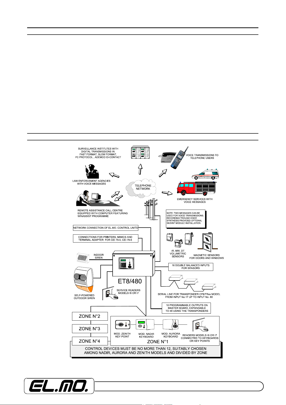
The ET8/480, ET8/480S and ET8/480PT model of microprocessor based control units have been designed in order to
enable the installation of high quality intrusion detection in residential homes, businesses, bank branches, post offices,
etc. it is possible also to create multi-istallation systems with up to four separte zones and a maximun of 80 double balanced inputs. The users who can be enabled to interact with the control unit are total 32 and they may gain access by
means of a code, an electronic proximity key from the following control devices:
NADIR = control and programming keyboard featuring a horizontal plastic casing of modern design, equipped with a backlit display for the display of operating and programming messages, four keys for part setting, back-lit rubber keys, a scanner for electronic proximity keys and a connector for the connection of other remote readers.
AURORA = control and programming keyboard featuring a horizontal plastic casing of modern design and four keys for
part setting, equipped with back-lit rubber keys, a scanner for electronic proximity keys and a connector for the connection
of other remote readers.
ZENITH = Remote control point, Key point, flush-mounting for 503-type frames equipped with four keys for part setting, a
scanner for electronic proximity keys and a connector for the connection of other remote readers.
NOTE: This manual is refered to ET8/480 base control unit. In particular cases ET8/480S and ET8/480PT’s characteristics will be indicated.
2. BLOCK DIAGRAM
ET8/480, ET8/480S and ET8/480PT - TECHNICAL MANUAL - 3

3. GENERAL FEATURES
For an accurate appraisal, the features of the ET8/480, ET8/480S and ET8/480PT models of control units are as follows:
- Control unit managed by microprocessor for high risk applications used in residential housing, banks, post offices and businesses;
- Multi-system functions covering up to four separate
zones with four part-set sections for each zone for total 16
part-set;
- 32 user codes and separate installation and programming
code;
- Built-in control keyboard with integrated proximity key scanner
(only in ET8/480 and ET8/480PT models);
- Connector for the connection of remote scanner (models I6
and I7) for proximity key;
- 16 inputs which can be connected directly to the master
board, expandable up to 80 inputs on serial bus;
- Inputs can be configured as double balanced or normally
closed;
- Fully compatible with CP8 series of transponder for serial
expansions;
- Balanced input for TAMPER protection of system, protection
against opening and removal (against tamper only on ET8/
480PT to protect double door housing with window);
- Self-recognition function of the connected periphericals,
keyboards and transponders after a total reset;
- RS485 serial port with terminal board connection to connect
the following type of control devices:
AURORA = Control and programming keyboard equipped with
back-lit rubber keys, four keys for part setting, a scanner for
electronic proximity keys and a connector for the connection of
other remote readers.
NADIR = Control and programming keyboard equipped with a
back-lit display for display purposes, four keys for part setting,
back-lit rubber keys, a scanner for electronic proximity keys and
a connector for the connection of other remote readers.
ZENITH = Remote control point, Key point, flush-mounting for
503-type frames equipped with four keys for part setting, a scanner for electronic proximity keys and a connector for the connection of other remote readers.
- Accessories to connect to control devices:
I6 or I7 = Scanner point for M4 proximity key connected to keyboard, Key point or directly to the control unit terminal board.
The I6 version is suitable for installation on the MAGIC TICINO
frame; the I7 version on the LIVING TICINO frame.
- Built-in time programmer for the automatic management of the
system or a portion of it, equipped with 24 programmes with
weekly/annual pattern and management of weekday holidays,
fixed or variable, management of overtime and automatic
changeover between GMT/BST and vice versa;
- Lithium back-up battery for internal clock;
- 300 events non-volatile log with FIFO management;
- Definition of events to be sent to printer and to be recorded in
the log;
- Programmability of communications parameters
according to CEI 79-5 and CEI 79-6 protocols;
- Exit timing programmable in blocks of 1 second for
each individual zone;
- General alarm timing programmable from 10 seconds
to 600 seconds in blocks of 10 seconds;
- Delay timing on entry, Pre-alarm, programmable for
each input from 0 to 65535 seconds in blocks of 1 seconds;
- Tamper alarm timing, TAMPER, programmable from 10
seconds to 600 seconds in blocks of 10 seconds;
- Delay timing for indication mains supply failure programmable in minutes from 0 to 60;
- Control unit operating and programming parameters of
the recorded in NVRAM memory;
- 16 programmable electronic MFT outputs divided
between two connectors SIGNAL 1 and SIGNAL 2, up to
80 on serial bus;
- Connector-type output for MP64/DRPT model driver
board for ET848/SIN mimic panel;
- CENTRONICS parallel port for printer with connectortype output;
- FX/232 optional connector for board with 2 RS232
serial ports, for connection with centralisations;
- RS232 serial port with MINIDIN connector for direct
programming by PC using WINASSIST programme or
dedicated browser with CP8/SER2 cable;
- Up-date of control unit release via PC with DOWN-
LOAD programme and CP8/SER2 cable;
- RS485 serial port with terminal board for serial bus
connection for transponders models CP8/TR8B, CP8/TR,
etc.
- RS485 serial port with terminal board for network connection of EL.MO. control units and alarm centralizations.
- C-NA-NC contacts outputs terminal of ALARM and
TAMPER relays;
- Separate terminals for self-powered sirens control and
for the relative internal battery recharging;
- Built-in telephone dialler to calls up to 12 telephone
users equipped with telephone line sectioning relay and
connection terminal board;
- FAST FORMAT DTMF, SLOW FORMAT EL.Mo PC
AND ADEMCO ID-CONTACT communication protocols;
- Connector for SK/SINT voice synthesis board connection for the transmission of two voice messages;
- Modem section for remote service using WINASSIST;
- New generation 2.5A high efficiency switching power
supply unit, for the mains supply of the system and the
recharging of the buffer battery.
4 - ET8/480, ET8/480S and ET8/480PT - TECHNICAL MANUAL

4. TECHNICAL SPECIFICATIONS
Model ET8/480 (ET8/480S).
Level of performance 2nd with device against removal mounted at installer’s discretion.
Degree of protection IP3X.
Mains supply 230V +/- 10% 50Hz via safety transformer fixed to the base of the
Battery recharge voltage 13.8V (13.4V / 14.4V).
Nominal output voltage 13V .
Normal functioning Between 9V and 15V .
Nominal current supplied 2.5A.
Limitation in current 2.7A.
Residual ripple 40 mV .
VOUT stabilisation +/- 2% at charge change.
Maximum consumption from mains 300 mA.
Battery recharge current 1.5A for 15Ah battery.
Maximum current on charge 700 mA.
Consumption @ 12V(ET8/480s with a
NADIR keyboard connected)
with control unit enabled:
with control unit disabled:
with control unit in alarm status:
Consumption of other accessories
possibly connected:
NADIR keyboard: Increase of 55 mA with system disabled, 90 mA with system enabled,
AURORA keyboard: Increase of 50 mA with system disabled, 80 mA with system enabled,
AURORA/SC keyboard Increase of 31 mA with system disabled, 53 mA with system enabled,
ZENITH Key point: Increase of 40 mA with system disabled, 70 mA with system enabled.
Readers I6 or I7: Increase of 30 mA.
SK/SINT voice synthesis card: Increase of 25 mA in stand-by mode and 40 mA in alarm mode.
CP8/TR two input/output type
transponders: 43 mA in stand-by mode and 73 mA with relays in pick-up mode
CP8/TRS two-input type transponders: 43 mA in stand-by mode.
CP8/TR8B eight-input type
transponders: 50 mA in stand-by mode without outputs connected.
CP8/TR8 eight-input type transponders: 50 mA in stand-by mode without outputs connected.
CP8/TR30 concentrator: 110 mA with just one TR9000 module connected, 140 mA with 30 TR9000
Board with RS232 double serial 80 mA.
Operating temperature - Humidity: +5 / +40 °C - 93% humidity.
Batteries which can be connected: 12V max. 15Ah.
Dimensions of casing: L 480 - H 305 - B 140 mm ( ET8/480PT L 525 - H 380 - B 280 mm).
Weight: 4 Kg ( 15 Kg for ET8/480PT)
Equipment: 33 1500 Ohm input balancing resistors, 2 termination resistors for 680 Ohm
housing; 12V 15 Ah max. back up battery.
300 mA (340 mA).
260 mA (300 mA).
360 mA (400 mA).
180 mA max.
107 mA max.
87 mA max.
connected.
serial line, small bag with 4 5x54 threading screws and 4 S8 wedge, microswitch against housing opening and removing (Against house-breaking kit
with inertial sensor and analysis board for ET8/480PT), rubber-sheathed
cable with connector for remote reader (not included as part of ET8/480S
equipment), technical and programming manual, Cd programming with
PDF manuals.
NOTE:
The transponders must be connected directly to the specific terminal board of the control unit indicated as A and B
and may be powered by the mains supply terminals of the keyboard. They must be connected according to this
manual’s diagrams by using a screened cable for theft and flame prevention with a minimum section of 0.75 mm2 for
short lengths and a minimum section of 1mm2 or greater for long lengths. Maximum connection distance between
control unit and the last transponder is 1,000 metres with transponders evenly distributed. For the system’s autonomy
and powered load’s optimization, it is reccomended the use of remote mains supply boxes such as model C11K,
especially when the control unit is used with several keyboards, transponders and volumetric sensors.
ET8/480, ET8/480S and ET8/480PT - TECHNICAL MANUAL - 5

ET8/480, ET8/480S and ET8/480PT models of control unit are compliant with CEI 79-2 standard is the level of
performance declared. They resulted immune to radio-frequency and voltage pulses to the mains supply terminals;
tests have been carried out according to IEC 801-2-3-4. They are also compliant with the 89/336/EEC directive relative
to electromagnetic compatibility and the 93/68/EEC directive relative to low voltage safety.
The telephone section provided with TLC 049407/00 Test Report dated 06/07/2000 issued by the Ministry of
Communications Accredited Laboratory No. 58.
The following programmaings degrade the performance level from 2nd to 1st:
- Inputs programming as NC and/or TR9000 and CT8/TR transponders.
The following functions and devices are not IMQ - SISTEMI DI SICUREZZA certified:
- Fire alarms management, command devices and inputs tamper disabling, self-disabling function relative to inputs in
anomaly conditions when exit time ends
- Printer mod. CP8/PRINT, transponder mod. CP8/TRS, Teleservice, WINASSIST software, modem mod CP8/MDE,
browser light WABL0034/CD, the use of TR9000 and TR9000S transponders, FAR and PTN filters.
.
5. INSTALLATION
ATTE NTIO N:
Ensure that electrical system is equipped with an efficient earth connection. The control unit includes a
telephone communicator which integrity depends on the earth system efficiency; in any case it is reccomended the use of appropriate auxiliary protection devices which should be connected outside the
metallic housings, such as FAR model for protection on the electric network and the PTN model for protection on the telephone system. Before proceeding with the installation, it is reccomanded to consult the
CEI 79-3 standard concerning the installation of security systems, the CEI 64-8 standard concerning the
installation of low-tension systems. Operate professionaly.
A = Check earth connection existence;
B = Control earth connection efficiency;
C = Assure the mains supply voltage quality, in order to avoid excess voltage which could occur in the case the control unit
were occasionally powered by a generating set;
D = Provide for the connection of devices outwardly the control unit for suppressing electrical interference (for example
FAR module);
E = If mains current instability occurs, provide for the connection of a saturated iron stabilizer;
F = Check the existence of a magnetothermal switch or arrange an adequate one, for protection against the mere over-
loading of the electrical system. In fact, although the additional use of a differential switch (cut-out switch) is provided by
law, in order to avoid the electrocution of individuals, valuations regarding both individuals safety (the equipment below the
switch is under low voltage) and the need to guarantee the surveillance system continuity, suggest the sole use of magnetothermal switch in order to guarantee the mains supply continuity;
G = In case of use of built-in telephone communicator, provided for the installation of a telephone interference suppression
filter mod. PTN;
This filter must be installed in close proximity instead of the telephone line fuse box; this does not permit the telephone line wires entering and exiting the dialler to be contained in the same duct since the interference on the entering
wire is filtered by the PTN module.
If PTN module is installed near the control unit’s housing, it is necessary to separate the entering and exiting telephone
line wires in two separate ducts, so as to avoid problems of mutual induction which may occur on the wires upstream the
PTN module.
H = Evaluate the configuration of the electrical connections of the various accessories (sensors, keyboards, sirens ...) for
the control unit’s optimal positioning;
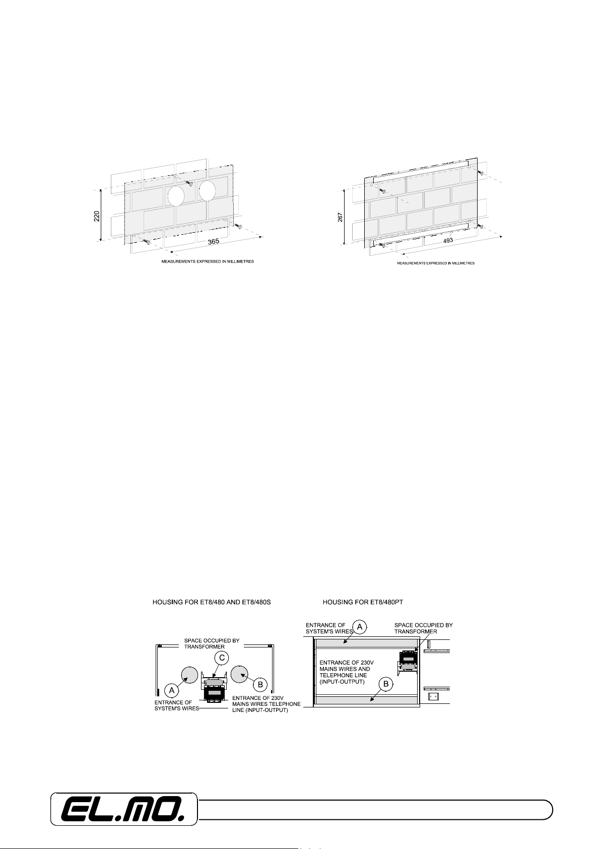
I = The control unit must be wall-mounted, in a suitable position to permit the access of wires for electricity mains supply
and telephone line, the system alarms wiring, the eventual connection of a printer and lastly subsequent maintenance
activities on the control unit itself.
THE WALL MUST BE ABLE TO SUPPORT THE CONTROL UNIT WEIGHT.
6 - ET8/480, ET8/480S and ET8/480PT - TECHNICAL MANUAL
Avoid to locate the control unit and its accessories in extremely hot and humid places. For instance keyboards must not be
placed in proximity of heat sources such as radiators, nor exposed to direct sunlight which would compromise the liquid
crystal display legibility. Position the control unit and the various accessories in environments which are not dusty and
avoid louver obstruction so as not to block the internal ventilation.
Before proceeding with the installation consult the CEI 79-3 standard concerning the installation of security systems, the
CEI 64-8 standard concerning installation of low-tension systems. Operate professionaly.
Operations for installation, drill holes marking and subsequent drilling
1 - Open the control unit by unscrewing the lateral screws on the upper side.
2 - Open the control unit door, take the manual out and prepare the panel for fixing.
3 - Fix the control unit to the wall by means of the specific screws and dowels using the holes previously drilled. NOTE:
The supplied screws are used for fixing to an homogeneous wall. Use specific screws and wedges for different
walls.
4 - Insert non-live wires of the system, through the holes indicated on the base of the control unit. If you choose to use the
upper and the bottom holes, you shall use tube/box connections with HB or higher flammability rating.
5 - Connect the transformer’s entry terminals to the powered-off mains cable inserted in the hole indicated as B. Avoid that
low voltage cables touched mains supplies cables. To serve this purpose, it is necessary to fix the mains cable to the
mother board’s connection terminal board by means of the rubber-sheathed supplied as standard issue. Carefully avoid
soldering the unshelded cables extremity before connection to terminal board.
6 - Check the accuracy of the connections to be made referring to the diagrams in this manual.
7 - Connect the telephone communicator’s input and output wires. If necessary pass them through the hole indicated as B.
8 - Connect the control devices, keyboards, Key point, with any electronic keys. Connect the telephone communicator if
required.
9 - Accurately check the wiring and connect the red and black wires with FASTON ends to the battery respecting polarity.
NOTE: The battery housing must have a flammability rating of HB or higher.
10 - Switch on the mains and consult the programming manual for installers.
11 - If PC with the specific programming program is available, connect the CP8/SER2 cable to the dedicated connector
and activate direct communication.
12 - Proceed M4 keys memorization to the pertinent keyboards.
13 - Test the system.
14 - Connect the sirens and carry out a final test.
15 - Close the control unit up using the screws provided.
ET8/480, ET8/480S and ET8/480PT - TECHNICAL MANUAL - 7
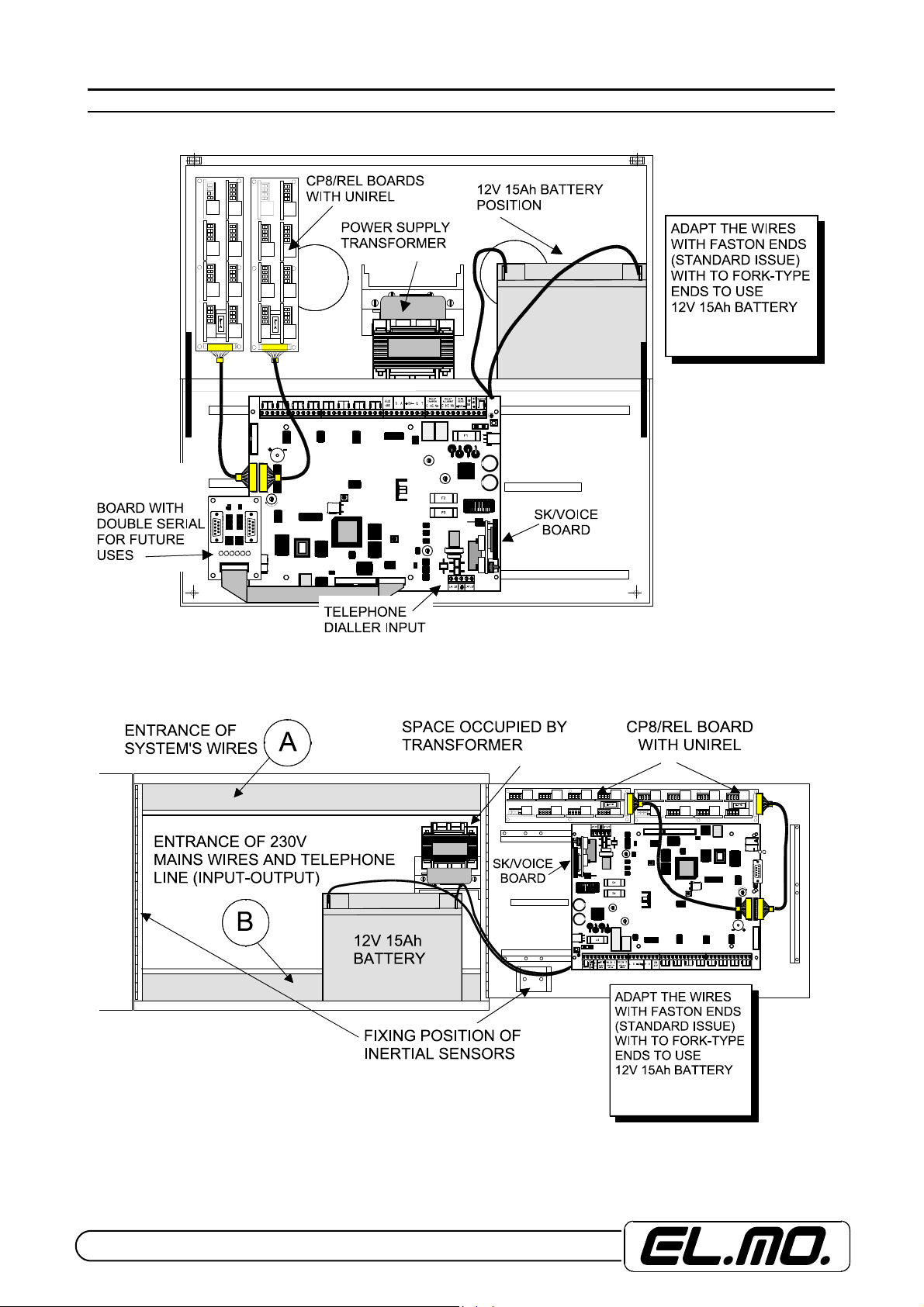
6. PREARRANGEMENTS
View of internal positionings ET8/480 and ET8/480S models.
View of internal positionings in ET8/480PT model.
8 - ET8/480, ET8/480S and ET8/480PT - TECHNICAL MANUAL
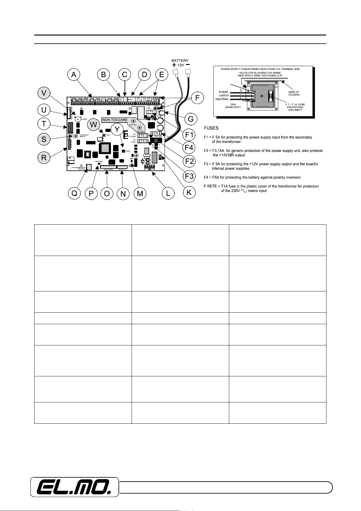
7. MASTER BOARD AND FUSES
View of master board and the power supply transformer
Key:
A = Terminal board for connection of
sensor wires
D = Driver terminals for compatible
keyboards, NADIR, AURORA and
ZENITH key points.
G = Connector-type input of the voltage
originating from the secondary of the
transformer fixed to the base of the
housing.
F3 = F 5A fuse protecting, see fuses table. F4 = T 5A fuse protecting, see fuses table. K = Connector for the connection of the
L = Connection terminal board of
telephone dialler section with earth
terminal and line sectioning. Connect only
to TNV circuit.
O = Connector for connection of printer
with Centronics parallel interface. Use, for
example, a CP8PRINT printer.
R = Connector for I6 or I7 reader.
S = Contrast adjustment of display.
V = Warning buzzer.
Items not available in ET8/480S control
unit.
W = SPEC push-button for special reset
operations to be used solely with ET8/48S
control unit.
B = RS485 AUX terminal board for
network connection of control units. To
use for connection with big alarm
centralization.
E = Output terminals for alarm signals,
clean contacts of the ALARM and
TAMPER relays (only for devices working
with SELV voltage), mains supply
terminals for sensors, reference for selfpowered sirens and +14V for recharging
their internal battery
F1 = F5A fuse protecting, see fuses table. F2 = F 3,15A fuse protecting, see fuses
M = Variation bond of the sensitivity to the
entering ring. Normally, the bond is closed
for standard sensitivity, open to reduce
the sensitivity.
P = Connection bond of the NIMH battery
for the clock. Close only after installation.
T = Signals 1 and 2 connectors for
connection of CP8/REL and UNIREL
boards for MFT output function.
Y = RESET push-button for resetting the
control unit or returning to factory status,
DEFAULT. These operations are
described in the pertinent section.
C = Driver terminals for transponder serial
line. The mains supply must be taken from
the terminal board alongside. If the serial
line starts from this terminal board,
connect the first 680 Ohm resistor
between A and B.
F = Input terminal board of the control
unit’s TAMPER circuit for the facilitated
connection of the housing protection
microswitch.
table.
SK/SINT voice synthesis card.
N = Connector for future uses.
Q = MINIDIN connector for the
programming in direct link-up with PC and
WINASSIST or specific BROWSER, for
the up-dating of the control unit release or
for connections with CEI 79-5/-6 protocol.
Use the CP8/SER2 cable.
U = Connector for the connection of the
MP64/DRTP driver board for the
ET848/SIN mimic repeater.
ET8/480, ET8/480S and ET8/480PT - TECHNICAL MANUAL - 9
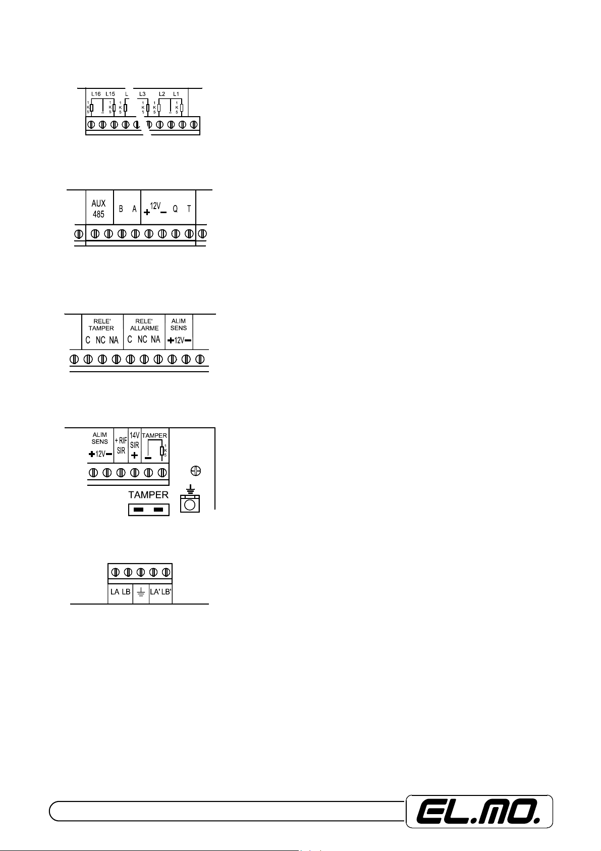
Description of the terminal boards
L1 ...L16
as double balanced or NC.
The events generated by the anomaly of each input can be programmed.
The inputs are 80 in total, the transponders of the CP80 CP90 CP100 series of control
units must be used from input 17 up to the last one to be managed.
AUX 485 = RS485 terminal board for connection to a network of El.Mo control units
managed by PC or in large centralisation systems.
B - A = Connection terminals of the RS485 serial port for a line of compatible
transponders with CP80, CP90, CP100 series of control units. The serial line makes it
possible to expand the control unit up to a maximum of 80 inputs.
It is necessary to connect the cable of the serial line with four wires, taking the mains
supply from the right-hand terminal board; in the event of connection with three wires
only the terminal B- A and the negative of the right-hand terminal board will be used.
With the serial line exiting from the terminal board, it is necessary to connect a 680
Ohm end resistor between the terminals A and B while the second one must be
connected to the same terminals of the last transponder used.
+ 12V - QT = RS485 terminals for connection of the external control mechanisms of
the control unit identificable in NADIR, AURORA, ZENITH models.
The mains supply terminals can also be used for supplying power to the transponder
devices of the serial line which may be connected in order to expand the system.
TAMPER RELAY C - NC - NA = Output terminals of the TAMPER alarm relay
corresponding to contacts free from potential. Contact capacity 800 mA @24V.
To use only for connection to circuit working with SELV voltage, for example to
drive optical-acoustic warning devices or inputs for radio links, etc.
= Input terminals of the lines with configuration which can be programmed
ALARM RELAY C - NC - NA = Output terminals of the general alarm relay
corresponding to contacts free from potential. Contact capacity 5A @24V. To use only
for connection to circuit working with SELV voltage, for example to drive optical-
acoustic warning devices or inputs for radio links, etc.
SENS. POWER +12V- = Output terminals for powering sensors or other devices,
the voltage is always present and the output is protected by the F3 F5A fuse.
+RIF SIR = Output terminal of the control voltage for self-powered sirens. The voltage
is present when the control unit is in stand-by; during general alarm status, the voltage
drops for the duration of the timing set when programming the control unit.
Use two wires for connection, one linked to the +RIF SIR and the other linked to the
left-hand negative terminal.
TAMPER = Connection terminal of the system TAMPER input to which the various
protection microswitches for the system’s housing or other connected devices must
link. The WHITE TAMPER CONNECTOR is positioned in series to this input; this
connector constitutes the point of connection of the control unit protection circuit made
off the microswitch protecting against housing opening placed in contact with the
screws fastening the door. It is possible to connect the base protection kit in series to
the latter, as shown in the diagram featured in this manual.
EARTH FASTON = Male connector for the earth connection of the control unit and
housing protections; the connection is made beforehand by the manufacturer.
LA, LB, LA’, LB’ = Connection terminals of the telephone dialler built into the master
board. Follow the connection diagram illustrated in this manual.The earth terminal is
placed between the telephone line input terminals (LA and LB) and the output
terminals (LA’ and LB’). To the earth terminal connects the standard protections of the
telephone interface. Make the connection to an effecient earth.
10 - ET8/480, ET8/480S and ET8/480PT - TECHNICAL MANUAL
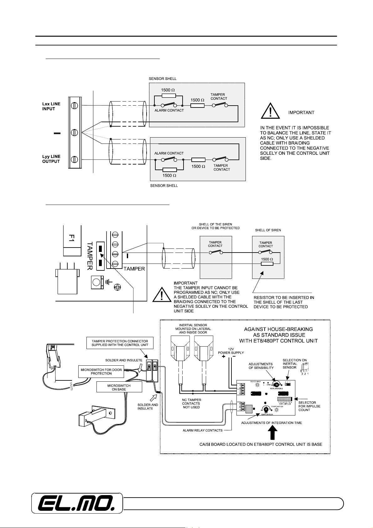
8. ELECTRICAL CONNECTIONS
8.1 Connection of double balanced inputs
Main diagram for double balanced connection
8.2 Connection of control unit TAMPER input
Main diagram for single balanced connection of system TAMPER protection input.
ET8/480, ET8/480S and ET8/480PT - TECHNICAL MANUAL - 11
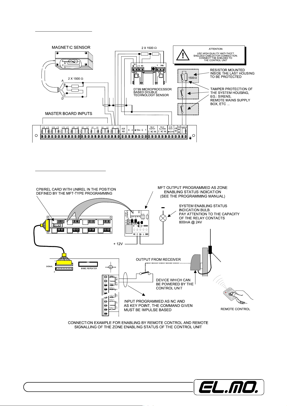
8.3 Connection of the inputs
Note: Inputs programming as NC lowers the level of performances from 2nd to 1st.
8.4 Connections for control inputs
Diagrams for the specific connection of an input for control of the control unit or part of it.
Note: The external source enabling command must be given as impulse by using a device of the same level or higher
installed inside the control unit housing and connected to an appropriately programmed line.
12 - ET8/480, ET8/480S and ET8/480PT - TECHNICAL MANUAL
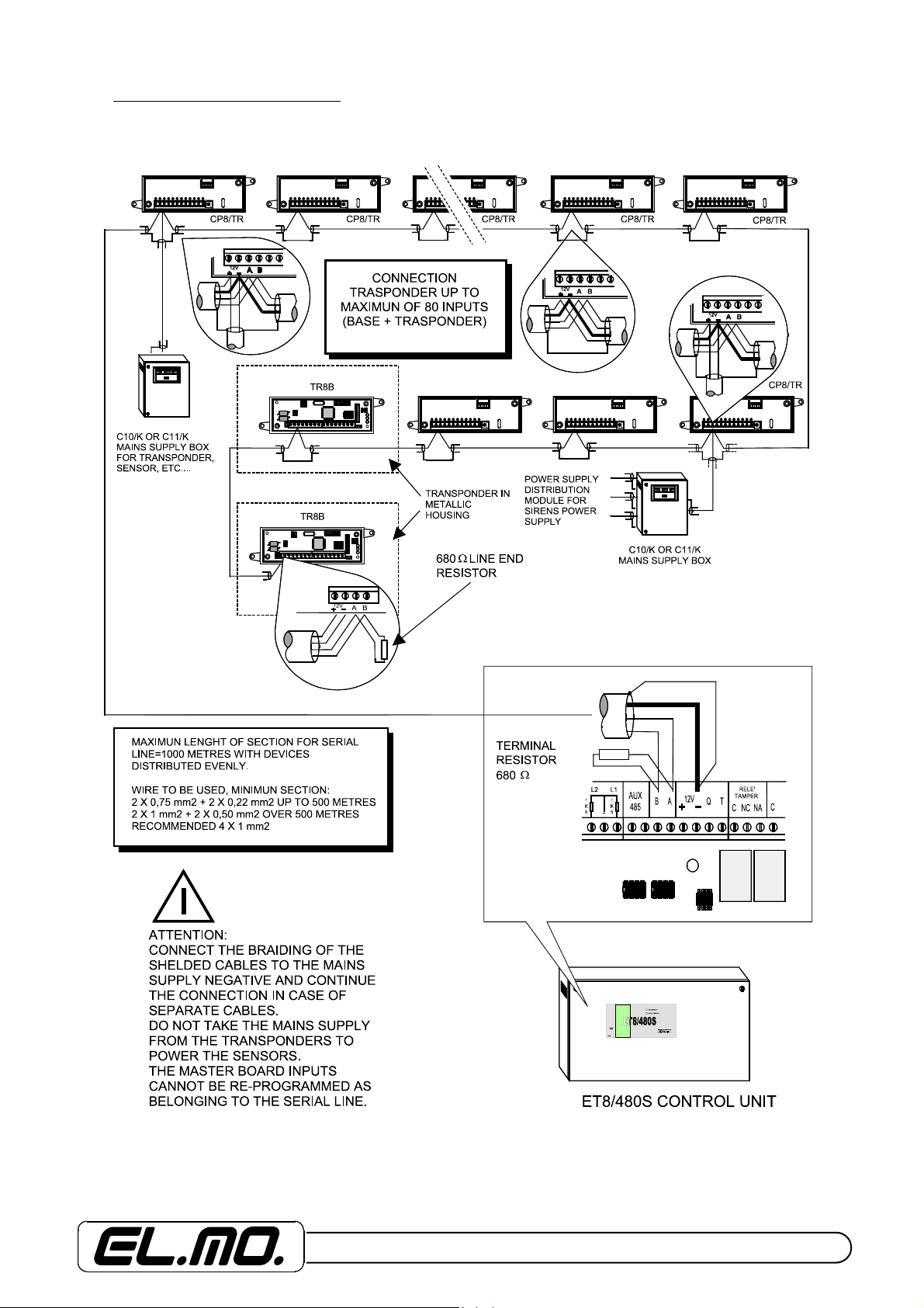
8.5 Connection of the transponder
Main diagram for transponder connection.
NOTE: The use of CP8/TRS mod. transponders is not certificated by IMQ-SISTEMI DI SICUREZZA.
ET8/480, ET8/480S and ET8/480PT - TECHNICAL MANUAL - 13
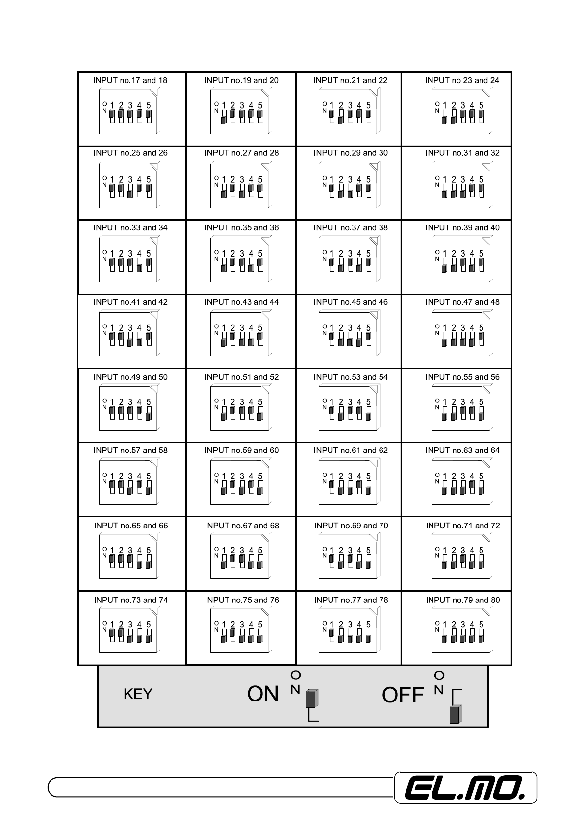
Diagram of addresses programming for the CP8/TR transponders.
14 - ET8/480, ET8/480S and ET8/480PT - TECHNICAL MANUAL
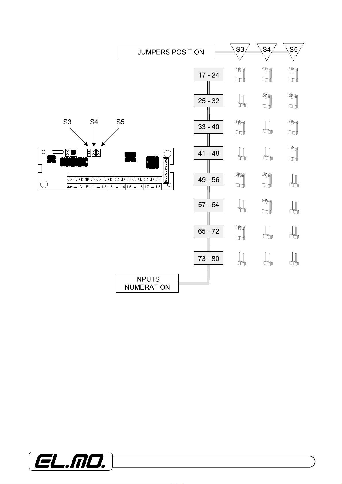
Diagram of addresses programming for the CP8/TR8 AND CP8/TR8B transponders.
ET8/480, ET8/480S and ET8/480PT - TECHNICAL MANUAL - 15
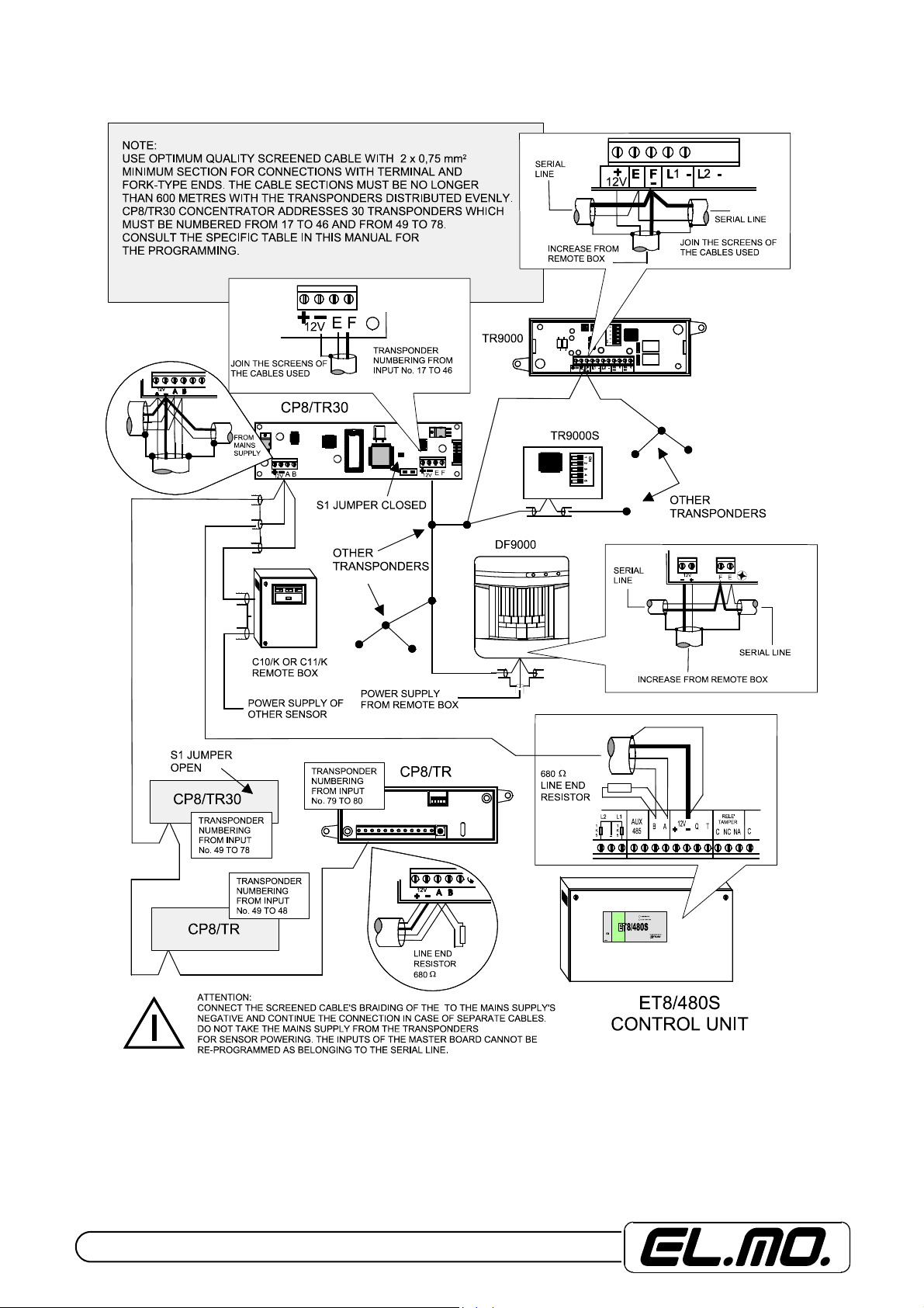
Connection of transponders mod. TR9000, TR9000S and DF9000.
NOTE: The use of TR9000 and TR9000S transponders is not certificated by IMQ-SISTEMI DI SICUREZZA.
16 - ET8/480, ET8/480S and ET8/480PT - TECHNICAL MANUAL
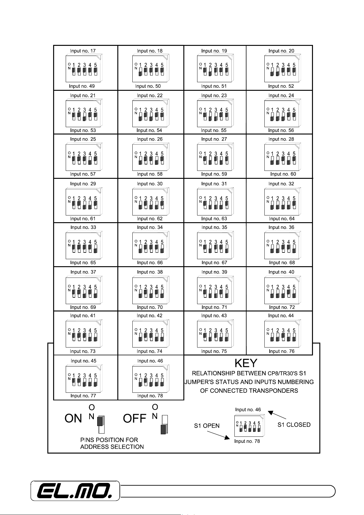
Diagram of TR9000, TR9000S transponders and DF9000 sensor’s addresses programming.
ET8/480, ET8/480S and ET8/480PT - TECHNICAL MANUAL - 17
 Loading...